EP1588889A2 - Electric traction assembly for fuel cell vehicle having an electric resistor for heat dissipation - Google Patents
Electric traction assembly for fuel cell vehicle having an electric resistor for heat dissipation Download PDFInfo
- Publication number
- EP1588889A2 EP1588889A2 EP05008359A EP05008359A EP1588889A2 EP 1588889 A2 EP1588889 A2 EP 1588889A2 EP 05008359 A EP05008359 A EP 05008359A EP 05008359 A EP05008359 A EP 05008359A EP 1588889 A2 EP1588889 A2 EP 1588889A2
- Authority
- EP
- European Patent Office
- Prior art keywords
- fuel cell
- electric
- cooling
- traction chain
- electrical
- Prior art date
- Legal status (The legal status is an assumption and is not a legal conclusion. Google has not performed a legal analysis and makes no representation as to the accuracy of the status listed.)
- Granted
Links
Images
Classifications
-
- B—PERFORMING OPERATIONS; TRANSPORTING
- B60—VEHICLES IN GENERAL
- B60L—PROPULSION OF ELECTRICALLY-PROPELLED VEHICLES; SUPPLYING ELECTRIC POWER FOR AUXILIARY EQUIPMENT OF ELECTRICALLY-PROPELLED VEHICLES; ELECTRODYNAMIC BRAKE SYSTEMS FOR VEHICLES IN GENERAL; MAGNETIC SUSPENSION OR LEVITATION FOR VEHICLES; MONITORING OPERATING VARIABLES OF ELECTRICALLY-PROPELLED VEHICLES; ELECTRIC SAFETY DEVICES FOR ELECTRICALLY-PROPELLED VEHICLES
- B60L15/00—Methods, circuits, or devices for controlling the traction-motor speed of electrically-propelled vehicles
- B60L15/20—Methods, circuits, or devices for controlling the traction-motor speed of electrically-propelled vehicles for control of the vehicle or its driving motor to achieve a desired performance, e.g. speed, torque, programmed variation of speed
- B60L15/2009—Methods, circuits, or devices for controlling the traction-motor speed of electrically-propelled vehicles for control of the vehicle or its driving motor to achieve a desired performance, e.g. speed, torque, programmed variation of speed for braking
-
- B—PERFORMING OPERATIONS; TRANSPORTING
- B60—VEHICLES IN GENERAL
- B60L—PROPULSION OF ELECTRICALLY-PROPELLED VEHICLES; SUPPLYING ELECTRIC POWER FOR AUXILIARY EQUIPMENT OF ELECTRICALLY-PROPELLED VEHICLES; ELECTRODYNAMIC BRAKE SYSTEMS FOR VEHICLES IN GENERAL; MAGNETIC SUSPENSION OR LEVITATION FOR VEHICLES; MONITORING OPERATING VARIABLES OF ELECTRICALLY-PROPELLED VEHICLES; ELECTRIC SAFETY DEVICES FOR ELECTRICALLY-PROPELLED VEHICLES
- B60L1/00—Supplying electric power to auxiliary equipment of vehicles
- B60L1/003—Supplying electric power to auxiliary equipment of vehicles to auxiliary motors, e.g. for pumps, compressors
-
- B—PERFORMING OPERATIONS; TRANSPORTING
- B60—VEHICLES IN GENERAL
- B60L—PROPULSION OF ELECTRICALLY-PROPELLED VEHICLES; SUPPLYING ELECTRIC POWER FOR AUXILIARY EQUIPMENT OF ELECTRICALLY-PROPELLED VEHICLES; ELECTRODYNAMIC BRAKE SYSTEMS FOR VEHICLES IN GENERAL; MAGNETIC SUSPENSION OR LEVITATION FOR VEHICLES; MONITORING OPERATING VARIABLES OF ELECTRICALLY-PROPELLED VEHICLES; ELECTRIC SAFETY DEVICES FOR ELECTRICALLY-PROPELLED VEHICLES
- B60L1/00—Supplying electric power to auxiliary equipment of vehicles
- B60L1/02—Supplying electric power to auxiliary equipment of vehicles to electric heating circuits
-
- B—PERFORMING OPERATIONS; TRANSPORTING
- B60—VEHICLES IN GENERAL
- B60L—PROPULSION OF ELECTRICALLY-PROPELLED VEHICLES; SUPPLYING ELECTRIC POWER FOR AUXILIARY EQUIPMENT OF ELECTRICALLY-PROPELLED VEHICLES; ELECTRODYNAMIC BRAKE SYSTEMS FOR VEHICLES IN GENERAL; MAGNETIC SUSPENSION OR LEVITATION FOR VEHICLES; MONITORING OPERATING VARIABLES OF ELECTRICALLY-PROPELLED VEHICLES; ELECTRIC SAFETY DEVICES FOR ELECTRICALLY-PROPELLED VEHICLES
- B60L3/00—Electric devices on electrically-propelled vehicles for safety purposes; Monitoring operating variables, e.g. speed, deceleration or energy consumption
- B60L3/0023—Detecting, eliminating, remedying or compensating for drive train abnormalities, e.g. failures within the drive train
- B60L3/003—Detecting, eliminating, remedying or compensating for drive train abnormalities, e.g. failures within the drive train relating to inverters
-
- B—PERFORMING OPERATIONS; TRANSPORTING
- B60—VEHICLES IN GENERAL
- B60L—PROPULSION OF ELECTRICALLY-PROPELLED VEHICLES; SUPPLYING ELECTRIC POWER FOR AUXILIARY EQUIPMENT OF ELECTRICALLY-PROPELLED VEHICLES; ELECTRODYNAMIC BRAKE SYSTEMS FOR VEHICLES IN GENERAL; MAGNETIC SUSPENSION OR LEVITATION FOR VEHICLES; MONITORING OPERATING VARIABLES OF ELECTRICALLY-PROPELLED VEHICLES; ELECTRIC SAFETY DEVICES FOR ELECTRICALLY-PROPELLED VEHICLES
- B60L3/00—Electric devices on electrically-propelled vehicles for safety purposes; Monitoring operating variables, e.g. speed, deceleration or energy consumption
- B60L3/0023—Detecting, eliminating, remedying or compensating for drive train abnormalities, e.g. failures within the drive train
- B60L3/0053—Detecting, eliminating, remedying or compensating for drive train abnormalities, e.g. failures within the drive train relating to fuel cells
-
- B—PERFORMING OPERATIONS; TRANSPORTING
- B60—VEHICLES IN GENERAL
- B60L—PROPULSION OF ELECTRICALLY-PROPELLED VEHICLES; SUPPLYING ELECTRIC POWER FOR AUXILIARY EQUIPMENT OF ELECTRICALLY-PROPELLED VEHICLES; ELECTRODYNAMIC BRAKE SYSTEMS FOR VEHICLES IN GENERAL; MAGNETIC SUSPENSION OR LEVITATION FOR VEHICLES; MONITORING OPERATING VARIABLES OF ELECTRICALLY-PROPELLED VEHICLES; ELECTRIC SAFETY DEVICES FOR ELECTRICALLY-PROPELLED VEHICLES
- B60L3/00—Electric devices on electrically-propelled vehicles for safety purposes; Monitoring operating variables, e.g. speed, deceleration or energy consumption
- B60L3/0023—Detecting, eliminating, remedying or compensating for drive train abnormalities, e.g. failures within the drive train
- B60L3/0061—Detecting, eliminating, remedying or compensating for drive train abnormalities, e.g. failures within the drive train relating to electrical machines
-
- B—PERFORMING OPERATIONS; TRANSPORTING
- B60—VEHICLES IN GENERAL
- B60L—PROPULSION OF ELECTRICALLY-PROPELLED VEHICLES; SUPPLYING ELECTRIC POWER FOR AUXILIARY EQUIPMENT OF ELECTRICALLY-PROPELLED VEHICLES; ELECTRODYNAMIC BRAKE SYSTEMS FOR VEHICLES IN GENERAL; MAGNETIC SUSPENSION OR LEVITATION FOR VEHICLES; MONITORING OPERATING VARIABLES OF ELECTRICALLY-PROPELLED VEHICLES; ELECTRIC SAFETY DEVICES FOR ELECTRICALLY-PROPELLED VEHICLES
- B60L3/00—Electric devices on electrically-propelled vehicles for safety purposes; Monitoring operating variables, e.g. speed, deceleration or energy consumption
- B60L3/0023—Detecting, eliminating, remedying or compensating for drive train abnormalities, e.g. failures within the drive train
- B60L3/0076—Detecting, eliminating, remedying or compensating for drive train abnormalities, e.g. failures within the drive train relating to braking
-
- B—PERFORMING OPERATIONS; TRANSPORTING
- B60—VEHICLES IN GENERAL
- B60L—PROPULSION OF ELECTRICALLY-PROPELLED VEHICLES; SUPPLYING ELECTRIC POWER FOR AUXILIARY EQUIPMENT OF ELECTRICALLY-PROPELLED VEHICLES; ELECTRODYNAMIC BRAKE SYSTEMS FOR VEHICLES IN GENERAL; MAGNETIC SUSPENSION OR LEVITATION FOR VEHICLES; MONITORING OPERATING VARIABLES OF ELECTRICALLY-PROPELLED VEHICLES; ELECTRIC SAFETY DEVICES FOR ELECTRICALLY-PROPELLED VEHICLES
- B60L3/00—Electric devices on electrically-propelled vehicles for safety purposes; Monitoring operating variables, e.g. speed, deceleration or energy consumption
- B60L3/06—Limiting the traction current under mechanical overload conditions
-
- B—PERFORMING OPERATIONS; TRANSPORTING
- B60—VEHICLES IN GENERAL
- B60L—PROPULSION OF ELECTRICALLY-PROPELLED VEHICLES; SUPPLYING ELECTRIC POWER FOR AUXILIARY EQUIPMENT OF ELECTRICALLY-PROPELLED VEHICLES; ELECTRODYNAMIC BRAKE SYSTEMS FOR VEHICLES IN GENERAL; MAGNETIC SUSPENSION OR LEVITATION FOR VEHICLES; MONITORING OPERATING VARIABLES OF ELECTRICALLY-PROPELLED VEHICLES; ELECTRIC SAFETY DEVICES FOR ELECTRICALLY-PROPELLED VEHICLES
- B60L50/00—Electric propulsion with power supplied within the vehicle
- B60L50/40—Electric propulsion with power supplied within the vehicle using propulsion power supplied by capacitors
-
- B—PERFORMING OPERATIONS; TRANSPORTING
- B60—VEHICLES IN GENERAL
- B60L—PROPULSION OF ELECTRICALLY-PROPELLED VEHICLES; SUPPLYING ELECTRIC POWER FOR AUXILIARY EQUIPMENT OF ELECTRICALLY-PROPELLED VEHICLES; ELECTRODYNAMIC BRAKE SYSTEMS FOR VEHICLES IN GENERAL; MAGNETIC SUSPENSION OR LEVITATION FOR VEHICLES; MONITORING OPERATING VARIABLES OF ELECTRICALLY-PROPELLED VEHICLES; ELECTRIC SAFETY DEVICES FOR ELECTRICALLY-PROPELLED VEHICLES
- B60L50/00—Electric propulsion with power supplied within the vehicle
- B60L50/50—Electric propulsion with power supplied within the vehicle using propulsion power supplied by batteries or fuel cells
- B60L50/51—Electric propulsion with power supplied within the vehicle using propulsion power supplied by batteries or fuel cells characterised by AC-motors
-
- B—PERFORMING OPERATIONS; TRANSPORTING
- B60—VEHICLES IN GENERAL
- B60L—PROPULSION OF ELECTRICALLY-PROPELLED VEHICLES; SUPPLYING ELECTRIC POWER FOR AUXILIARY EQUIPMENT OF ELECTRICALLY-PROPELLED VEHICLES; ELECTRODYNAMIC BRAKE SYSTEMS FOR VEHICLES IN GENERAL; MAGNETIC SUSPENSION OR LEVITATION FOR VEHICLES; MONITORING OPERATING VARIABLES OF ELECTRICALLY-PROPELLED VEHICLES; ELECTRIC SAFETY DEVICES FOR ELECTRICALLY-PROPELLED VEHICLES
- B60L58/00—Methods or circuit arrangements for monitoring or controlling batteries or fuel cells, specially adapted for electric vehicles
- B60L58/30—Methods or circuit arrangements for monitoring or controlling batteries or fuel cells, specially adapted for electric vehicles for monitoring or controlling fuel cells
- B60L58/32—Methods or circuit arrangements for monitoring or controlling batteries or fuel cells, specially adapted for electric vehicles for monitoring or controlling fuel cells for controlling the temperature of fuel cells, e.g. by controlling the electric load
- B60L58/33—Methods or circuit arrangements for monitoring or controlling batteries or fuel cells, specially adapted for electric vehicles for monitoring or controlling fuel cells for controlling the temperature of fuel cells, e.g. by controlling the electric load by cooling
-
- B—PERFORMING OPERATIONS; TRANSPORTING
- B60—VEHICLES IN GENERAL
- B60L—PROPULSION OF ELECTRICALLY-PROPELLED VEHICLES; SUPPLYING ELECTRIC POWER FOR AUXILIARY EQUIPMENT OF ELECTRICALLY-PROPELLED VEHICLES; ELECTRODYNAMIC BRAKE SYSTEMS FOR VEHICLES IN GENERAL; MAGNETIC SUSPENSION OR LEVITATION FOR VEHICLES; MONITORING OPERATING VARIABLES OF ELECTRICALLY-PROPELLED VEHICLES; ELECTRIC SAFETY DEVICES FOR ELECTRICALLY-PROPELLED VEHICLES
- B60L58/00—Methods or circuit arrangements for monitoring or controlling batteries or fuel cells, specially adapted for electric vehicles
- B60L58/40—Methods or circuit arrangements for monitoring or controlling batteries or fuel cells, specially adapted for electric vehicles for controlling a combination of batteries and fuel cells
-
- B—PERFORMING OPERATIONS; TRANSPORTING
- B60—VEHICLES IN GENERAL
- B60L—PROPULSION OF ELECTRICALLY-PROPELLED VEHICLES; SUPPLYING ELECTRIC POWER FOR AUXILIARY EQUIPMENT OF ELECTRICALLY-PROPELLED VEHICLES; ELECTRODYNAMIC BRAKE SYSTEMS FOR VEHICLES IN GENERAL; MAGNETIC SUSPENSION OR LEVITATION FOR VEHICLES; MONITORING OPERATING VARIABLES OF ELECTRICALLY-PROPELLED VEHICLES; ELECTRIC SAFETY DEVICES FOR ELECTRICALLY-PROPELLED VEHICLES
- B60L7/00—Electrodynamic brake systems for vehicles in general
- B60L7/02—Dynamic electric resistor braking
- B60L7/06—Dynamic electric resistor braking for vehicles propelled by ac motors
-
- B—PERFORMING OPERATIONS; TRANSPORTING
- B60—VEHICLES IN GENERAL
- B60L—PROPULSION OF ELECTRICALLY-PROPELLED VEHICLES; SUPPLYING ELECTRIC POWER FOR AUXILIARY EQUIPMENT OF ELECTRICALLY-PROPELLED VEHICLES; ELECTRODYNAMIC BRAKE SYSTEMS FOR VEHICLES IN GENERAL; MAGNETIC SUSPENSION OR LEVITATION FOR VEHICLES; MONITORING OPERATING VARIABLES OF ELECTRICALLY-PROPELLED VEHICLES; ELECTRIC SAFETY DEVICES FOR ELECTRICALLY-PROPELLED VEHICLES
- B60L2240/00—Control parameters of input or output; Target parameters
- B60L2240/10—Vehicle control parameters
- B60L2240/12—Speed
-
- B—PERFORMING OPERATIONS; TRANSPORTING
- B60—VEHICLES IN GENERAL
- B60L—PROPULSION OF ELECTRICALLY-PROPELLED VEHICLES; SUPPLYING ELECTRIC POWER FOR AUXILIARY EQUIPMENT OF ELECTRICALLY-PROPELLED VEHICLES; ELECTRODYNAMIC BRAKE SYSTEMS FOR VEHICLES IN GENERAL; MAGNETIC SUSPENSION OR LEVITATION FOR VEHICLES; MONITORING OPERATING VARIABLES OF ELECTRICALLY-PROPELLED VEHICLES; ELECTRIC SAFETY DEVICES FOR ELECTRICALLY-PROPELLED VEHICLES
- B60L2240/00—Control parameters of input or output; Target parameters
- B60L2240/10—Vehicle control parameters
- B60L2240/36—Temperature of vehicle components or parts
-
- B—PERFORMING OPERATIONS; TRANSPORTING
- B60—VEHICLES IN GENERAL
- B60L—PROPULSION OF ELECTRICALLY-PROPELLED VEHICLES; SUPPLYING ELECTRIC POWER FOR AUXILIARY EQUIPMENT OF ELECTRICALLY-PROPELLED VEHICLES; ELECTRODYNAMIC BRAKE SYSTEMS FOR VEHICLES IN GENERAL; MAGNETIC SUSPENSION OR LEVITATION FOR VEHICLES; MONITORING OPERATING VARIABLES OF ELECTRICALLY-PROPELLED VEHICLES; ELECTRIC SAFETY DEVICES FOR ELECTRICALLY-PROPELLED VEHICLES
- B60L2240/00—Control parameters of input or output; Target parameters
- B60L2240/40—Drive Train control parameters
- B60L2240/42—Drive Train control parameters related to electric machines
- B60L2240/423—Torque
-
- B—PERFORMING OPERATIONS; TRANSPORTING
- B60—VEHICLES IN GENERAL
- B60L—PROPULSION OF ELECTRICALLY-PROPELLED VEHICLES; SUPPLYING ELECTRIC POWER FOR AUXILIARY EQUIPMENT OF ELECTRICALLY-PROPELLED VEHICLES; ELECTRODYNAMIC BRAKE SYSTEMS FOR VEHICLES IN GENERAL; MAGNETIC SUSPENSION OR LEVITATION FOR VEHICLES; MONITORING OPERATING VARIABLES OF ELECTRICALLY-PROPELLED VEHICLES; ELECTRIC SAFETY DEVICES FOR ELECTRICALLY-PROPELLED VEHICLES
- B60L2240/00—Control parameters of input or output; Target parameters
- B60L2240/40—Drive Train control parameters
- B60L2240/42—Drive Train control parameters related to electric machines
- B60L2240/425—Temperature
-
- B—PERFORMING OPERATIONS; TRANSPORTING
- B60—VEHICLES IN GENERAL
- B60L—PROPULSION OF ELECTRICALLY-PROPELLED VEHICLES; SUPPLYING ELECTRIC POWER FOR AUXILIARY EQUIPMENT OF ELECTRICALLY-PROPELLED VEHICLES; ELECTRODYNAMIC BRAKE SYSTEMS FOR VEHICLES IN GENERAL; MAGNETIC SUSPENSION OR LEVITATION FOR VEHICLES; MONITORING OPERATING VARIABLES OF ELECTRICALLY-PROPELLED VEHICLES; ELECTRIC SAFETY DEVICES FOR ELECTRICALLY-PROPELLED VEHICLES
- B60L2240/00—Control parameters of input or output; Target parameters
- B60L2240/40—Drive Train control parameters
- B60L2240/42—Drive Train control parameters related to electric machines
- B60L2240/429—Current
-
- B—PERFORMING OPERATIONS; TRANSPORTING
- B60—VEHICLES IN GENERAL
- B60L—PROPULSION OF ELECTRICALLY-PROPELLED VEHICLES; SUPPLYING ELECTRIC POWER FOR AUXILIARY EQUIPMENT OF ELECTRICALLY-PROPELLED VEHICLES; ELECTRODYNAMIC BRAKE SYSTEMS FOR VEHICLES IN GENERAL; MAGNETIC SUSPENSION OR LEVITATION FOR VEHICLES; MONITORING OPERATING VARIABLES OF ELECTRICALLY-PROPELLED VEHICLES; ELECTRIC SAFETY DEVICES FOR ELECTRICALLY-PROPELLED VEHICLES
- B60L2240/00—Control parameters of input or output; Target parameters
- B60L2240/60—Navigation input
- B60L2240/66—Ambient conditions
- B60L2240/662—Temperature
-
- B—PERFORMING OPERATIONS; TRANSPORTING
- B60—VEHICLES IN GENERAL
- B60L—PROPULSION OF ELECTRICALLY-PROPELLED VEHICLES; SUPPLYING ELECTRIC POWER FOR AUXILIARY EQUIPMENT OF ELECTRICALLY-PROPELLED VEHICLES; ELECTRODYNAMIC BRAKE SYSTEMS FOR VEHICLES IN GENERAL; MAGNETIC SUSPENSION OR LEVITATION FOR VEHICLES; MONITORING OPERATING VARIABLES OF ELECTRICALLY-PROPELLED VEHICLES; ELECTRIC SAFETY DEVICES FOR ELECTRICALLY-PROPELLED VEHICLES
- B60L2260/00—Operating Modes
- B60L2260/10—Temporary overload
- B60L2260/16—Temporary overload of electrical drive trains
-
- B—PERFORMING OPERATIONS; TRANSPORTING
- B60—VEHICLES IN GENERAL
- B60L—PROPULSION OF ELECTRICALLY-PROPELLED VEHICLES; SUPPLYING ELECTRIC POWER FOR AUXILIARY EQUIPMENT OF ELECTRICALLY-PROPELLED VEHICLES; ELECTRODYNAMIC BRAKE SYSTEMS FOR VEHICLES IN GENERAL; MAGNETIC SUSPENSION OR LEVITATION FOR VEHICLES; MONITORING OPERATING VARIABLES OF ELECTRICALLY-PROPELLED VEHICLES; ELECTRIC SAFETY DEVICES FOR ELECTRICALLY-PROPELLED VEHICLES
- B60L2260/00—Operating Modes
- B60L2260/20—Drive modes; Transition between modes
- B60L2260/26—Transition between different drive modes
-
- B—PERFORMING OPERATIONS; TRANSPORTING
- B60—VEHICLES IN GENERAL
- B60L—PROPULSION OF ELECTRICALLY-PROPELLED VEHICLES; SUPPLYING ELECTRIC POWER FOR AUXILIARY EQUIPMENT OF ELECTRICALLY-PROPELLED VEHICLES; ELECTRODYNAMIC BRAKE SYSTEMS FOR VEHICLES IN GENERAL; MAGNETIC SUSPENSION OR LEVITATION FOR VEHICLES; MONITORING OPERATING VARIABLES OF ELECTRICALLY-PROPELLED VEHICLES; ELECTRIC SAFETY DEVICES FOR ELECTRICALLY-PROPELLED VEHICLES
- B60L2270/00—Problem solutions or means not otherwise provided for
- B60L2270/44—Heat storages, e.g. for cabin heating
-
- B—PERFORMING OPERATIONS; TRANSPORTING
- B60—VEHICLES IN GENERAL
- B60L—PROPULSION OF ELECTRICALLY-PROPELLED VEHICLES; SUPPLYING ELECTRIC POWER FOR AUXILIARY EQUIPMENT OF ELECTRICALLY-PROPELLED VEHICLES; ELECTRODYNAMIC BRAKE SYSTEMS FOR VEHICLES IN GENERAL; MAGNETIC SUSPENSION OR LEVITATION FOR VEHICLES; MONITORING OPERATING VARIABLES OF ELECTRICALLY-PROPELLED VEHICLES; ELECTRIC SAFETY DEVICES FOR ELECTRICALLY-PROPELLED VEHICLES
- B60L2270/00—Problem solutions or means not otherwise provided for
- B60L2270/46—Heat pumps, e.g. for cabin heating
-
- Y—GENERAL TAGGING OF NEW TECHNOLOGICAL DEVELOPMENTS; GENERAL TAGGING OF CROSS-SECTIONAL TECHNOLOGIES SPANNING OVER SEVERAL SECTIONS OF THE IPC; TECHNICAL SUBJECTS COVERED BY FORMER USPC CROSS-REFERENCE ART COLLECTIONS [XRACs] AND DIGESTS
- Y02—TECHNOLOGIES OR APPLICATIONS FOR MITIGATION OR ADAPTATION AGAINST CLIMATE CHANGE
- Y02T—CLIMATE CHANGE MITIGATION TECHNOLOGIES RELATED TO TRANSPORTATION
- Y02T10/00—Road transport of goods or passengers
- Y02T10/60—Other road transportation technologies with climate change mitigation effect
- Y02T10/64—Electric machine technologies in electromobility
-
- Y—GENERAL TAGGING OF NEW TECHNOLOGICAL DEVELOPMENTS; GENERAL TAGGING OF CROSS-SECTIONAL TECHNOLOGIES SPANNING OVER SEVERAL SECTIONS OF THE IPC; TECHNICAL SUBJECTS COVERED BY FORMER USPC CROSS-REFERENCE ART COLLECTIONS [XRACs] AND DIGESTS
- Y02—TECHNOLOGIES OR APPLICATIONS FOR MITIGATION OR ADAPTATION AGAINST CLIMATE CHANGE
- Y02T—CLIMATE CHANGE MITIGATION TECHNOLOGIES RELATED TO TRANSPORTATION
- Y02T10/00—Road transport of goods or passengers
- Y02T10/60—Other road transportation technologies with climate change mitigation effect
- Y02T10/70—Energy storage systems for electromobility, e.g. batteries
-
- Y—GENERAL TAGGING OF NEW TECHNOLOGICAL DEVELOPMENTS; GENERAL TAGGING OF CROSS-SECTIONAL TECHNOLOGIES SPANNING OVER SEVERAL SECTIONS OF THE IPC; TECHNICAL SUBJECTS COVERED BY FORMER USPC CROSS-REFERENCE ART COLLECTIONS [XRACs] AND DIGESTS
- Y02—TECHNOLOGIES OR APPLICATIONS FOR MITIGATION OR ADAPTATION AGAINST CLIMATE CHANGE
- Y02T—CLIMATE CHANGE MITIGATION TECHNOLOGIES RELATED TO TRANSPORTATION
- Y02T10/00—Road transport of goods or passengers
- Y02T10/60—Other road transportation technologies with climate change mitigation effect
- Y02T10/72—Electric energy management in electromobility
-
- Y—GENERAL TAGGING OF NEW TECHNOLOGICAL DEVELOPMENTS; GENERAL TAGGING OF CROSS-SECTIONAL TECHNOLOGIES SPANNING OVER SEVERAL SECTIONS OF THE IPC; TECHNICAL SUBJECTS COVERED BY FORMER USPC CROSS-REFERENCE ART COLLECTIONS [XRACs] AND DIGESTS
- Y02—TECHNOLOGIES OR APPLICATIONS FOR MITIGATION OR ADAPTATION AGAINST CLIMATE CHANGE
- Y02T—CLIMATE CHANGE MITIGATION TECHNOLOGIES RELATED TO TRANSPORTATION
- Y02T90/00—Enabling technologies or technologies with a potential or indirect contribution to GHG emissions mitigation
- Y02T90/10—Technologies relating to charging of electric vehicles
- Y02T90/16—Information or communication technologies improving the operation of electric vehicles
-
- Y—GENERAL TAGGING OF NEW TECHNOLOGICAL DEVELOPMENTS; GENERAL TAGGING OF CROSS-SECTIONAL TECHNOLOGIES SPANNING OVER SEVERAL SECTIONS OF THE IPC; TECHNICAL SUBJECTS COVERED BY FORMER USPC CROSS-REFERENCE ART COLLECTIONS [XRACs] AND DIGESTS
- Y02—TECHNOLOGIES OR APPLICATIONS FOR MITIGATION OR ADAPTATION AGAINST CLIMATE CHANGE
- Y02T—CLIMATE CHANGE MITIGATION TECHNOLOGIES RELATED TO TRANSPORTATION
- Y02T90/00—Enabling technologies or technologies with a potential or indirect contribution to GHG emissions mitigation
- Y02T90/40—Application of hydrogen technology to transportation, e.g. using fuel cells
Definitions
- the present invention relates to automotive fuel cell vehicles. More particularly, it relates to the management of electrical energy in certain phases transient.
- electric machines are reversible. So, in a motor vehicle with electric traction, the electric machine coupled mechanically to the drive wheels can be used in electric motor to ensure the propulsion of the vehicle, providing electric power to the electric machine. This can also be used as an electric generator during the braking phases of the vehicle and in this case it transforms the mechanical energy of braking into energy the vehicle must absorb, possibly by heat dissipation. This operating mode is often called "electric braking".
- Patent Application WO96 / 41393 describes a fuel cell for a vehicle in which electrical resistance is immersed in the liquid of the cooling circuit of the fuel cell to heat the fuel cell very quickly.
- the electrical resistance may, if necessary, be supplied with electric current by producing electrical energy when braking the vehicle to accelerate the implementation temperature of the battery or to keep it in temperature.
- US Patent 6,448,535 discloses also describes a fuel cell for a vehicle in which an electrical resistance is dipped into the liquid from a primary circuit cooling the battery to fuel to prevent the liquid from freezing because it is, according to this patent, necessarily de-ionized water.
- This primary cooling circuit is connected thermally to a secondary liquid cooling circuit with which it exchange his calories.
- the secondary cooling circuit is alone provided with a exchange radiator with the atmosphere and is also used to cool an engine electric.
- the objective of the invention is to provide a solution for the management of the powers which is well adapted to face in all circumstances the phases of brutal braking a fuel cell vehicle.
- the invention proposes an electric traction chain for a vehicle, said chain of traction comprising a power line, a fuel cell connected to the line an electric power management unit comprising a control module of the fuel cell, a control member at the disposal of a driver of the vehicle to control a deceleration thereof, the control member being connected at the management unit, at least one electric machine connected to at least one drive wheel, connected to the power line by means of an electronic control module of the electric machine, the electrical machine being connected to a second circuit of cooling in which circulates a coolant, independent of the first cooling circuit, an electrical dissipation resistor, means for, in deceleration demand case, and when the management unit detects that the power absorbed by the loads is less than the power sent on the power line, order the fuel cell control module to stop the process of generating electrical energy while connecting said dissipation resistor to said electric line.
- the invention proposes to dissipate in electric resistance electrical energy excessively produced by one or more electric traction machines driven by way to produce electric braking and by fuel cell for a certain time due to its inertia of operation.
- a resistance is used. electrical device immersed in a liquid of a coolant circuit.
- the invention preferably provides two circuits of separate cooling systems: a first liquid cooling circuit cooling ensures cooling of the fuel cell, and a second circuit cooling system, independent of the first mentioned, concerns the or the electric machines connected to the driving wheels as well as the modules control electronics, including those driving these electrical machines, and the electrical dissipation resistor is immersed in the first circuit of cooling.
- a fuel cell 3 connected to a power management unit electrical 6 by a power line 60.
- the fuel cell is a battery polymer membrane (PEFC) or alkaline battery (AFC).
- PEFC battery polymer membrane
- AFC alkaline battery
- a electric machine 4 intended to be used as a traction motor or as a generator during the phases of electrical braking.
- the electric machine 4 is connected to at least a driving wheel 40.
- the electronic control module of the electric machine is a inverter 5.
- An electrical line 61 connects the electrical energy management unit 6 to the inverter 5, and an electrical line 62 connects the inverter 5 to the electrical machine 4.
- the traction chain according to the invention preferably comprises a storage device electrical energy, connected to the power line 61 via the management unit 6 of electrical energy, and connected to the electrical energy management unit 6 by means of of an electrical line 63.
- This device for storing electrical energy is advantageously a bank of super capacitors 7.
- the first cooling circuit 1 comprises a first radiator 10 for dissipating calories to the ambient atmosphere, a hydraulic pump 13, a pipe 12 ensuring the distribution of the coolant from the first radiator 10 to fuel cell 3.
- the coolant may be a deionized liquid for electricity, for example water or a mixture of water and Deionized glycol, as it circulates within the fuel cell itself (depending on the importance of this electrical aspect, ie if it is important to increase the electrical impedance of the branch constituted by this cooling circuit). Meaning Heat transfer fluid circulation is indicated in the drawing. We also see a line 14 returning the coolant after warming up since the stack 3 to the first radiator 10 ensuring a heat exchange with the ambient air. As is well known, the cooling of the radiator 10 is made more efficient by the action a fan 11 ensuring a forced circulation of the ambient air through the radiator 10.
- the second cooling circuit 2 independent of the first circuit 1 and in which circulates a cooling liquid.
- the second cooling circuit 2 uses another independent heat transfer fluid charge the first charge used in the first cooling circuit.
- the cooling circuit is thermally independent of the first circuit of cooling 1: it comprises a second radiator 20 for dissipating calories to the ambient atmosphere, different from the first radiator 10, a hydraulic pump 23 and a network of pipes providing the distribution of coolant to the different organs that must be cooled.
- the direction of circulation of the coolant is indicated on the drawing.
- the second cooling circuit 2 establishes a circulation of coolant in several electrical components.
- the liquid of cooling is for example ordinary water or a mixture of water and glycol.
- the traction chain or even more generally the vehicle propelled by the chain of traction according to the invention could possibly comprise different modules other than the already mentioned inverter 5, the second circuit of cooling 2 establishing a circulation of coolant in several electronic management modules.
- the electronic modules of management cooled by means of a coolant are connected to the second circuit cooling 2.
- all the electrical components cooled by means of a liquid of are connected to this second cooling circuit 2.
- the electric machine 4 mechanically connected to the driving wheel or wheels 40 of the vehicle is connected to this second cooling circuit 2.
- all the electrical components cooled by means of a liquid of cooling are connected to the second cooling circuit 2.
- An electrical dissipation resistor 8 is installed in the first circuit of This dissipation resistor 8 is connected to the electrical line 61 via an electronic switch 81, itself controlled by the energy management unit Electric 6.
- the electric power management unit 6 receives information from the vehicle driver and information describing the operational status of the vehicle, such as the speed of movement. In the electric traction phase, the unit of electrical energy management 6 directly connects the fuel cell 3 to the inverter 5 and the inverter 5 transmit the electrical energy in the form appropriate to the electric machine 4 so that it operates as a motor. Depending on the circumstances, the electric power management unit 6 can also connect the super bench capacitors 7 to the electrical line 61 during the phases of engine operation in order to draw electrical energy in reserve in the bank of super capacitors 7 for add it to the energy from the fuel cell 3.
- Each of the two cooling circuits is preferably temperature controlled, for example by means of a thermostat not shown. Since the circuits are independent, the control temperature of each of these can be different.
- the ideal control temperature for a fuel cell is a little more high that the ideal control temperature of the circuit ensuring the cooling of the electric machine 4 and electronic components associated therewith.
- the control temperature is of the order of 60 ° C to 90 ° C for a battery polymer membrane (PEFC) and it is of the order of 45 ° C to 65 ° C for the circuit ensuring the cooling of the electric machine 4 and the electronic components which are associates.
- PEFC battery polymer membrane
- the inverter 5 drives the machine 4 electric generator so that it returns electrical energy on the line 61. If the electrical energy thus returned on line 61 is greater than the requirements of the vehicle, ie the energy absorbed by the other connected electrical loads in line 61 such as those mentioned above, then piloting the battery to fuel 3 stops the operation of it. Like the inertia of a battery fuel is very low, fuel cell 3 is rapidly ceasing to communicate calories to the coolant circulating in the first circuit of 1. During operation in electric braking, all loads connected to line 61 will absorb some of the electrical energy available. Also, the electrical energy management unit 6 sends the energy electrical priority to the bank of super capacitors 7, in the limit where these have not reached their maximum load.
- the management unit of the electrical energy 6 closes the switch 81 to add the dissipation resistor 8 as electric charge.
- This resistor is able to absorb the maximum current injected on the line 61 by the electrical machine or machines 4.
- the electrical resistance 8 of dissipation heats up and the calories are evacuated as the fluid cooling that takes them to the first radiator 10.
- the installation is dimensioned so that even when the electrical resistance of dissipation 8 is covered by the maximum possible current, the heating of the liquid of cooling inside the cooling circuit 1 remains compatible with the proper operation of the fuel cell 3.
- the efficiency of the evacuation of the calories produced by the dissipation resistor 8 is such as, in comparison with a dissipation resistor which would be cooled in air, we can use resistors 8 much more compact. In addition, there is no degradation of the coefficient of penetration into the vehicle air. Indeed, we use the ability of the radiator 10 to evacuate calories at a time when it would not have been used because of stopping the operation of the fuel cell. Thus, we managed to arrange the cooling circuits so as to make the best use of their capacities and taking advantage of the mutually exclusive character of the operation of the fuel cell its maximum load and the use of dissipation resistor 8 at its expense Max.
Abstract
Description
La présente invention se rapporte aux véhicules automobiles à pile à combustible. Plus particulièrement, elle se rapporte à la gestion de l'énergie électrique dans certaines phases transitoires.The present invention relates to automotive fuel cell vehicles. More particularly, it relates to the management of electrical energy in certain phases transient.
Il est bien connu que l'une des possibilités pour fabriquer de l'énergie électrique à bord d'un véhicule est d'utiliser une pile à combustible. Malheureusement, certaines phases transitoires, notamment lorsque l'on souhaite freiner brutalement le véhicule, peuvent être assez problématiques car il est difficile d'annuler brutalement la puissance produite par les piles à combustibles. C'est plus particulièrement le cas lorsque la pile à combustible est alimentée en oxygène en comprimant l'air ambiant en temps réel au moment de l'utilisation, au lieu d'être alimentée directement en oxygène pur. Dans certaines configurations et notamment la dernière citée, on a observé que la réaction d'une pile à combustible aux changements de puissance est peu dynamique, beaucoup moins dynamique qu'un moteur à combustion interne.It is well known that one of the possibilities for making electrical energy on board of a vehicle is to use a fuel cell. Unfortunately, some phases transients, especially when it is desired to brake the vehicle suddenly, may to be quite problematic because it is difficult to abruptly cancel the power produced by fuel cells. This is particularly the case when the battery fuel is supplied with oxygen by compressing ambient air in real time at time of use, instead of being fed directly with pure oxygen. In certain configurations and in particular the last cited, it was observed that the reaction of a fuel cell to power changes is not very dynamic, a lot less dynamic than an internal combustion engine.
Ceci est vrai aussi bien lorsque le besoin en puissance augmente que lorsque le besoin en puissance diminue. Dans certains cas, par exemple lorsque le conducteur du véhicule souhaite brutalement ralentir alors que juste auparavant il commandait une pleine accélération, la puissance électrique consommée par un véhicule à pile à combustible peut diminuer très brutalement, beaucoup plus rapidement que la puissance produite par la pile. Or, il se peut que le stockage d'énergie électrique soit impossible, par exemple parce qu'il n'y a pas d'accumulateur électrique ou parce que, si le véhicule est pourvu d'une batterie d'accumulateurs, ceux-ci sont déjà à leur charge maximale.This is true both when the need for power increases and when the need for power decreases. In some cases, for example when the driver of the vehicle want to brutally slow down whereas just before he was ordering a full acceleration, the electric power consumed by a fuel cell vehicle can decrease very sharply, much faster than the power produced by the battery. However, it is possible that the storage of electrical energy is impossible, for example because there is no electric accumulator or because, if the vehicle is equipped of a storage battery, these are already at their maximum load.
Par ailleurs, il est bien connu que les machines électriques sont réversibles. Ainsi, dans un véhicule automobile à traction électrique, la machine électrique couplée mécaniquement aux roues motrices peut être utilisée en moteur électrique pour assurer la propulsion du véhicule, en fournissant de l'énergie électrique à la machine électrique. Celle-ci peut être utilisée aussi en génératrice électrique pendant les phases de freinage du véhicule et dans ce cas elle transforme l'énergie mécanique de freinage en énergie électrique que le véhicule doit absorber, éventuellement par dissipation thermique. Ce mode de fonctionnement est souvent appelé « freinage électrique ».Moreover, it is well known that electric machines are reversible. So, in a motor vehicle with electric traction, the electric machine coupled mechanically to the drive wheels can be used in electric motor to ensure the propulsion of the vehicle, providing electric power to the electric machine. This can also be used as an electric generator during the braking phases of the vehicle and in this case it transforms the mechanical energy of braking into energy the vehicle must absorb, possibly by heat dissipation. This operating mode is often called "electric braking".
Si un objectif de bon sens est bien entendu de récupérer autant que possible l'énergie lors des freinages du véhicule, on sait que cette récupération se heurte aux caractéristiques des dispositifs de stockage de l'énergie électrique connus actuellement. Si l'on fait fonctionner la machine électrique en génératrice au couple maximal dont elle est capable, on va renvoyer sur la ligne électrique un courant très intense. Or, la plupart des batteries ne sont pas capables d'absorber des courants de charge importants. Seuls les condensateurs peuvent absorber des courants de charge aussi importants que les courants de décharge, mais leur capacité de stockage reste faible. La technologie des super condensateurs peut s'avérer intéressante pour les applications automobiles en offrant une capacité de stockage par unité de masse (c'est à dire une densité d'énergie) plus importante que les condensateurs et permettant des courants de charge plus importants que les batteries. Malgré tout, installer des accumulateurs entraíne toujours une augmentation de poids proportionnelle à leur capacité de stockage, à même technologie, et de plus, quelle que soit la technologie utilisée pour stocker l'énergie électrique, on se heurtera toujours à l'impossibilité de poursuivre l'accumulation d'énergie électrique lorsque l'état de charge des dispositifs utilisés est à son maximum. If a common sense goal is, of course, to recover as much energy as possible vehicle braking, it is known that this recovery is hampered by the characteristics of the electrical energy storage devices currently known. If we do operate the electric machine as a generator at the maximum torque of which it is capable, we will send back on the power line a very intense current. But most batteries are not able to absorb large load currents. Only capacitors can absorb load currents as large as currents discharge, but their storage capacity remains low. Super technology capacitors can prove to be attractive for automotive applications by offering a storage capacity per unit mass (ie energy density) more important that capacitors and allowing larger load currents than the batteries. Nevertheless, installing batteries always leads to a increase in weight proportional to their storage capacity, with the same technology, and moreover, whatever the technology used to store the electrical energy, we will always face the impossibility of continuing the accumulation of electrical energy when the state of charge of the devices used is at its maximum.
Or, il est intéressant de pouvoir, malgré tout, continuer à utiliser la ou les machines électriques en génératrice pour assurer la décélération ou le freinage du véhicule ne fût-ce que pour alléger la sollicitation des freins mécaniques du véhicule. Il est en effet avantageux de n'utiliser ceux-ci que dans les manoeuvres d'urgence ou pour les freinages les plus importants afin d'éviter un échauffement important en utilisation courante. De plus, le freinage électrique apporte un confort de conduite comparable au ressenti amené dans un véhicule conventionnel par le frein moteur, ce qui est de nature à faciliter la prise en main de tels véhicules par des conducteurs dont les réflexes ont été forgés par la conduite de ces véhicules conventionnels.However, it is interesting to be able, despite everything, to continue using the machine (s) electric generators to ensure the deceleration or braking of the vehicle even if that to lighten the load of the mechanical brakes of the vehicle. It is indeed advantageous to use these only in emergency maneuvers or for braking the most important ones in order to avoid a significant heating in everyday use. Of Moreover, the electric braking brings a comfort of conduct comparable to the felt brought in a conventional vehicle by the engine brake, which is likely to facilitate the grip such vehicles by drivers whose reflexes have been forged by the driving these conventional vehicles.
Pour toutes les raisons évoquées ci-dessus, il est utile de pouvoir maintenir un freinage électrique alors même que la pile à combustible continue momentanément à produire de l'énergie électrique.For all the reasons mentioned above, it is useful to be able to maintain a braking while the fuel cell momentarily continues to produce electrical energy.
La demande de brevet WO96/41393 décrit une pile à combustible pour véhicule dans laquelle une résistance électrique est plongée dans le liquide du circuit de refroidissement de la pile à combustible pour pouvoir réchauffer très vite la pile à combustible. La résistance électrique peut le cas échéant être alimentée en courant électrique en produisant de l'énergie électrique lors du freinage du véhicule pour accélérer la mise en température de la pile ou pour la maintenir en température. Le brevet US 6,448,535 décrit aussi décrit une pile à combustible pour véhicule dans laquelle une résistance électrique est plongée dans le liquide d'un circuit primaire de refroidissement de la pile à combustible pour pouvoir éviter que le liquide gèle car celui-ci est, selon ce brevet, nécessairement de l'eau dé-ionisée. Ce circuit primaire de refroidissement est relié thermiquement à un circuit secondaire de refroidissement par liquide avec lequel il échange ses calories. Le circuit secondaire de refroidissement est seul pourvu d'un radiateur d'échange avec l'atmosphère et est aussi utilisé pour refroidir un moteur électrique. Patent Application WO96 / 41393 describes a fuel cell for a vehicle in which electrical resistance is immersed in the liquid of the cooling circuit of the fuel cell to heat the fuel cell very quickly. The electrical resistance may, if necessary, be supplied with electric current by producing electrical energy when braking the vehicle to accelerate the implementation temperature of the battery or to keep it in temperature. US Patent 6,448,535 discloses also describes a fuel cell for a vehicle in which an electrical resistance is dipped into the liquid from a primary circuit cooling the battery to fuel to prevent the liquid from freezing because it is, according to this patent, necessarily de-ionized water. This primary cooling circuit is connected thermally to a secondary liquid cooling circuit with which it exchange his calories. The secondary cooling circuit is alone provided with a exchange radiator with the atmosphere and is also used to cool an engine electric.
Quant au brevet US 6,448,535, il propose d'utiliser un moteur électrique de traction refroidi par liquide, le liquide échangeant dans ce cas ses calories dans le circuit de refroidissement par liquide caloporteur implanté sur le véhicule. On pourrait alors aboutir à un échauffement excessif si l'on dissipe en plus dans le circuit de refroidissement des calories au moyen de la résistance électrique plongée dans le circuit de refroidissement.As for US Patent 6,448,535, it proposes to use an electric traction motor cooled liquid, the liquid exchanging in this case its calories in the circuit of coolant cooling installed on the vehicle. We could then succeed overheating if you dissipate more in the cooling circuit of calories by means of the electrical resistance dipped in the cooling circuit.
Se pose alors le problème d'une gestion efficace de certaines phases de freinage du véhicule, notamment en cas de freinage appuyé et brutal.Then there is the problem of effective management of certain braking phases of the vehicle, particularly in case of heavy and brutal braking.
L'objectif de l'invention est d'apporter une solution pour la gestion des puissances qui soit bien adaptée pour faire face en toutes circonstances aux phases de freinage brutal d'un véhicule à pile à combustible.The objective of the invention is to provide a solution for the management of the powers which is well adapted to face in all circumstances the phases of brutal braking a fuel cell vehicle.
L'invention propose une chaíne de traction électrique pour véhicule, ladite chaíne de traction comprenant une ligne électrique, une pile à combustible raccordée à la ligne électrique, une unité de gestion de l'énergie électrique comprenant un module de pilotage de la pile à combustible, un organe de commande à la disposition d'un conducteur du véhicule pour commander une décélération de celui-ci, l'organe de commande étant relié à l'unité de gestion, au moins une machine électrique reliée à au moins une roue motrice, connectée à la ligne électrique au moyen d'un module électronique de pilotage de la machine électrique, la machine électrique étant reliée à un second circuit de refroidissement dans lequel circule un liquide de refroidissement, indépendant du premier circuit de refroidissement, une résistance électrique de dissipation, des moyens pour, en cas de demande de décélération, et lorsque l'unité de gestion détecte que la puissance absorbée par les charges est inférieure à la puissance envoyée sur la ligne électrique, ordonner au module de pilotage de la pile à combustible d'arrêter le processus de production d'énergie électrique tout en connectant ladite résistance de dissipation à ladite ligne électrique.The invention proposes an electric traction chain for a vehicle, said chain of traction comprising a power line, a fuel cell connected to the line an electric power management unit comprising a control module of the fuel cell, a control member at the disposal of a driver of the vehicle to control a deceleration thereof, the control member being connected at the management unit, at least one electric machine connected to at least one drive wheel, connected to the power line by means of an electronic control module of the electric machine, the electrical machine being connected to a second circuit of cooling in which circulates a coolant, independent of the first cooling circuit, an electrical dissipation resistor, means for, in deceleration demand case, and when the management unit detects that the power absorbed by the loads is less than the power sent on the power line, order the fuel cell control module to stop the process of generating electrical energy while connecting said dissipation resistor to said electric line.
Ainsi, l'invention propose de dissiper dans une résistance électrique l'énergie électrique excédentaire produite à la fois par une ou des machines électriques de traction pilotées de façon à produire un freinage électrique et par la pile à combustible pendant un certain temps dû à son inertie de fonctionnement.Thus, the invention proposes to dissipate in electric resistance electrical energy excessively produced by one or more electric traction machines driven by way to produce electric braking and by fuel cell for a certain time due to its inertia of operation.
De préférence, pour assurer une dissipation très efficace, on utilise une résistance électrique plongée dans un liquide d'un circuit de refroidissement à liquide caloporteur.Preferably, to ensure a very efficient dissipation, a resistance is used. electrical device immersed in a liquid of a coolant circuit.
En outre, ayant observé que, en cas de freinage électrique, la pile à combustible ne sera très rapidement plus sollicitée, l'invention prévoit de préférence deux circuits de refroidissement séparés : un premier circuit de refroidissement à liquide de refroidissement assure le refroidissement de la pile à combustible, et un deuxième circuit de refroidissement à liquide de refroidissement, indépendant du premier cité, concerne la ou les machines électriques reliées aux roues motrices ainsi que les modules électroniques de commande, notamment ceux pilotant ces machines électriques, et la résistance électrique de dissipation est immergée dans le premier circuit de refroidissement.In addition, having observed that, in the event of electrical braking, the fuel cell will not be very rapidly more solicited, the invention preferably provides two circuits of separate cooling systems: a first liquid cooling circuit cooling ensures cooling of the fuel cell, and a second circuit cooling system, independent of the first mentioned, concerns the or the electric machines connected to the driving wheels as well as the modules control electronics, including those driving these electrical machines, and the electrical dissipation resistor is immersed in the first circuit of cooling.
Puisque la pile à combustible ne sera plus sollicitée pendant les phases de freinage électrique, la puissance de refroidissement du circuit de refroidissement de cette partie du véhicule ne sera très rapidement plus sollicitée, au delà des effets de l'inertie de la pile à combustible. On comprend donc que la meilleure implantation pour la résistance électrique de dissipation de l'énergie électrique de freinage est dans celui des circuits de refroidissement qui concerne la pile à combustible. En effet, côté machine électrique reliée aux roues motrices du véhicule, que l'on fonctionne en traction ou en freinage, cette machine électrique est susceptible d'être sollicitée au maximum de ses capacités, ainsi que tous les organes de commande de celle-ci. Or le rendement est sensiblement le même quel que soit le sens de la transformation d'énergie (énergie électrique en énergie cinétique, ou inversement). Les pertes responsables d'un dégagement de calories sont donc toujours sensiblement les mêmes.Since the fuel cell will no longer be used during the braking phases electric, the cooling power of the cooling circuit of this part of the vehicle will be very quickly solicited, beyond the effects of the inertia of the battery to combustible. So we understand that the best implementation for resistance electrical energy dissipation of braking energy is in that of the circuits of cooling which concerns the fuel cell. Indeed, electric machine side connected to the driving wheels of the vehicle, whether it is operated in traction or braking, this electric machine is likely to be requested to the maximum of its capacities, as well as all the controls thereof. However, the yield is substantially the even whatever the meaning of the transformation of energy (electric energy into energy kinetic, or vice versa). The losses responsible for calorie release are so always substantially the same.
Utiliser le circuit de refroidissement de la ou des machines électriques couplées mécaniquement aux roues pour en plus refroidir la résistance électrique de dissipation reviendrait à solliciter d'autant plus ce circuit de refroidissement et à devoir le dimensionner en conséquence. On se débarrasse de cette contrainte en installant la résistance électrique de dissipation dans le circuit de refroidissement de la pile à combustible car, pendant les phases de freinage électrique, ce circuit n'est sollicité que pendant un temps réduit, fonction de l'inertie de la pile à combustible. La puissance de refroidissement de ce circuit de refroidissement est donc disponible pour évacuer les calories produites par la résistance électrique de dissipation.Use the cooling circuit of the coupled electrical machine (s) mechanically to the wheels to additionally cool the dissipation electrical resistance would be to request all the more this cooling circuit and to have the sizing accordingly. We get rid of this constraint by installing the electrical dissipation resistance in the cooling circuit of the battery to because during the electrical braking phases this circuit is only for a short time, depending on the inertia of the fuel cell. The power of Cooling of this cooling circuit is therefore available to evacuate calories produced by the electrical resistance of dissipation.
Il est judicieux de prévoir deux circuits de refroidissement séparés pour une autre raison : les niveaux de température des circuits peuvent être différents. On aura intérêt à travailler à environ 90°C par exemple pour le circuit de refroidissement d'un moteur thermique ou 70°C à 80°C par exemple pour le circuit de refroidissement d'une pile à combustible et à température de 50°C par exemple, voire moins si possible, sur le circuit de refroidissement des machines électriques et dispositifs de commande associés.It is a good idea to have two separate cooling circuits for another reason: the temperature levels of the circuits may be different. We will be interested in working at about 90 ° C for example for the cooling circuit of a heat engine or 70 ° C to 80 ° C for example for the cooling circuit of a fuel cell and to temperature of 50 ° C for example, or even less if possible, on the circuit of cooling of electrical machines and associated control devices.
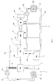
La suite de la description permet de bien faire comprendre tous les aspects de l'invention en s'appuyant sur la figure unique qui illustre de façon non limitative les circuits de refroidissement installés sur un véhicule à pile à combustible. The remainder of the description makes it possible to clearly understand all the aspects of the invention. relying on the single figure which illustrates in a non-limiting way the circuits of installed on a fuel cell vehicle.
A la figure 1, on voit une pile à combustible 3 reliée à une unité de gestion de l'énergie
électrique 6 par une ligne électrique 60. De préférence, la pile à combustible est une pile
à membrane polymère (PEFC) ou une pile alcaline (AFC). On voit également une
machine électrique 4 destinée à être utilisée en moteur de traction ou en génératrice
pendant les phases de freinage électrique. La machine électrique 4 est reliée à au moins
une roue motrice 40. Le module électronique de pilotage de la machine électrique est un
onduleur 5. Une ligne électrique 61 relie l'unité de gestion de l'énergie électrique 6 à
l'onduleur 5, et une ligne électrique 62 relie l'onduleur 5 à la machine électrique 4. Bien
entendu, d'autres charges électriques (non représentées sur la figure) sont connectées à la
ligne 61, comme par exemple le climatiseur du véhicule, de nombreuses fonctions
périphériques comme l'éclairage du véhicule, ou d'autres fonctions principales dont le
contrôle, jadis essentiellement par voie mécanique, bascule vers une commande
électrique comme la direction, les freins ou même la suspension des véhicules.In Figure 1, we see a
La chaíne de traction selon l'invention comporte de préférence un dispositif de stockage
de l'énergie électrique, raccordé à la ligne électrique 61 via l'unité de gestion 6 de
l'énergie électrique, et raccordé à l'unité de gestion de l'énergie électrique 6 au moyen
d'une ligne électrique 63. Ce dispositif de stockage de l'énergie électrique est
avantageusement un banc de super condensateurs 7.The traction chain according to the invention preferably comprises a storage device
electrical energy, connected to the
Un premier circuit de refroidissement 1 dans lequel circule une première charge de
liquide de refroidissement assure le refroidissement de la pile à combustible 3. Le
premier circuit de refroidissement 1 comporte un premier radiateur 10 de dissipation des
calories vers l'atmosphère ambiante, une pompe hydraulique 13, une canalisation 12
assurant la distribution du liquide de refroidissement depuis le premier radiateur 10 vers
la pile à combustible 3. Le liquide de refroidissement peut être un liquide dé-ionisé pour
être non conducteur de l'électricité, par exemple de l'eau ou un mélange d'eau et de
glycol dé-ionisé, dans la mesure où il circule au sein même de la pile à combustible
(selon l'importance de cet aspect électrique, c'est-à-dire s'il est important d'augmenter
l'impédance électrique de la branche constituée par ce circuit de refroidissement). Le sens
de circulation du liquide caloporteur est indiqué sur le dessin. On voit également une
canalisation 14 ramenant le liquide de refroidissement après son échauffement depuis la
pile 3 vers le premier radiateur 10 assurant un échange thermique avec l'air ambiant.
Comme bien connu, le refroidissement du radiateur 10 est rendu plus efficace par l'action
d'un ventilateur 11 assurant une circulation forcée de l'air ambiant au travers du
radiateur 10.A first cooling circuit 1 in which a first charge of
coolant provides cooling of the
On voit également un second circuit de refroidissement 2 indépendant du premier circuit
de refroidissement 1 et dans lequel circule un liquide de refroidissement. Le second
circuit de refroidissement 2 utilise une autre charge de liquide caloporteur indépendante
de la première charge utilisée dans le premier circuit de refroidissement. On peut utiliser
éventuellement dans les deux circuit un liquide caloporteur de même nature mais en tout
cas les charges sont séparées et donc les liquides ne se mélangent pas. Le second circuit
de refroidissement est en outre thermiquement indépendant du premier circuit de
refroidissement 1 : il comporte un second radiateur 20 de dissipation des calories vers
l'atmosphère ambiante, différent du premier radiateur 10, une pompe hydraulique 23 et
un réseau de tuyaux assurant la distribution du liquide de refroidissement vers les
différents organes qu'il faut refroidir. Le sens de circulation du liquide caloporteur est
indiqué sur le dessin. Le second circuit de refroidissement 2 établit une circulation de
liquide de refroidissement dans plusieurs composants électriques. Le liquide de
refroidissement est par exemple de l'eau ordinaire ou un mélange d'eau et de glycol.We also see a
La chaíne de traction, ou même plus généralement le véhicule propulsé par la chaíne de
traction selon l'invention, pourrait comporter éventuellement différents modules
électroniques de gestion autre que l'onduleur 5 déjà cité, le second circuit de
refroidissement 2 établissant une circulation de liquide de refroidissement dans plusieurs
modules électroniques de gestion. De préférence, tous les modules électroniques de
gestion refroidis au moyen d'un liquide de refroidissement sont reliés au second circuit
de refroidissement 2.The traction chain, or even more generally the vehicle propelled by the chain of
traction according to the invention could possibly comprise different modules
other than the already mentioned
De préférence, tous les composants électriques refroidis au moyen d'un liquide de
refroidissement sont reliés à ce second circuit de refroidissement 2. De façon
avantageuse, la machine électrique 4 mécaniquement reliée à la ou aux roues motrices 40
du véhicule est reliée à ce second circuit de refroidissement 2.Preferably, all the electrical components cooled by means of a liquid of
are connected to this
Ainsi, on voit un réseau de tuyaux 22 assurant la distribution du liquide de
refroidissement à basse température à la machine électrique 4, à l'onduleur 5 et à l'unité
de gestion de l'énergie électrique 6. On voit également un réseau de tuyaux 24 ramenant
le liquide de refroidissement après son échauffement depuis l'unité de gestion de
l'énergie électrique 6, depuis l'onduleur 5 et depuis la machine électrique 4 vers le
second radiateur 20. Comme bien connu en soi, l'efficacité de l'échange thermique du
second radiateur 20 est renforcée par l'action d'un ventilateur 21 assurant une circulation
forcée de l'air ambiant au travers du second radiateur 20.Thus, we see a network of
Avantageusement, tous les composants électriques refroidis au moyen d'un liquide de
refroidissement sont reliés au second circuit de refroidissement 2.Advantageously, all the electrical components cooled by means of a liquid of
cooling are connected to the
Une résistance électrique de dissipation 8 est installée dans le premier circuit de
refroidissement 1. Cette résistance de dissipation 8 est reliée à la ligne électrique 61 via
un interrupteur électronique 81, lui-même commandé par l'unité de gestion de l'énergie
électrique 6.An
L'unité de gestion de l'énergie électrique 6 reçoit des informations provenant du
conducteur du véhicule et des informations décrivant l'état de fonctionnement du
véhicule, comme la vitesse de déplacement. En phase de traction électrique, l'unité de
gestion de l'énergie électrique 6 connecte directement la pile à combustible 3 à
l'onduleur 5 et l'onduleur 5 transmet l'énergie électrique sous la forme appropriée à la
machine électrique 4 afin que celle-ci fonctionne en moteur. Selon les circonstances,
l'unité de gestion de l'énergie électrique 6 peut également connecter le banc de super
condensateurs 7 à la ligne électrique 61 pendant les phases de fonctionnement en moteur
afin de puiser l'énergie électrique en réserve dans le banc de super condensateurs 7 pour
l'ajouter à l'énergie provenant de la pile à combustible 3.The electric
Chacun des deux circuits de refroidissement est de préférence régulé en température, par
exemple au moyen d'un thermostat non représenté. Puisque les circuits sont
indépendants, la température de régulation de chacun de ceux-ci peut être différente. Par
exemple, la température de régulation idéale pour une pile à combustible est un peu plus
élevée que la température de régulation idéale du circuit assurant le refroidissement de la
machine électrique 4 et des composants électroniques qui lui sont associés. A titre
d'illustration, la température de régulation est de l'ordre de 60°C à 90°C pour une pile à
membrane polymère (PEFC) et elle est de l'ordre de 45°C à 65°C pour le circuit assurant
le refroidissement de la machine électrique 4 et des composants électroniques qui lui sont
associés.Each of the two cooling circuits is preferably temperature controlled, for
example by means of a thermostat not shown. Since the circuits are
independent, the control temperature of each of these can be different. By
example, the ideal control temperature for a fuel cell is a little more
high that the ideal control temperature of the circuit ensuring the cooling of the
Lorsque le mode de fonctionnement du véhicule contrôlé par l'unité de gestion de
l'énergie électrique 6 passe en freinage électrique, l'onduleur 5 pilote la machine
électrique 4 en génératrice de façon à ce qu'elle renvoie de l'énergie électrique sur la
ligne 61. Si l'énergie électrique ainsi renvoyée sur la ligne 61 est supérieure aux besoins
du véhicule, c'est à dire à l'énergie absorbée par les autres charges électriques connectées
à la ligne 61 telles que celles évoquées ci-dessus, alors le pilotage de la pile à
combustible 3 arrête le fonctionnement de celle-ci. Comme l'inertie d'une pile à
combustible est très faible, la pile à combustible 3 cesse rapidement de communiquer des
calories au liquide de refroidissement circulant dans le premier circuit de
refroidissement 1. Pendant le fonctionnement en freinage électrique, toutes les charges
électriques connectées à la ligne 61 vont absorber une partie de l'énergie électrique
disponible. Egalement, l'unité de gestion de l'énergie électrique 6 envoie l'énergie
électrique en priorité vers le banc de super condensateurs 7, dans la limite où ceux-ci
n'ont pas atteint leur charge maximale.When the mode of operation of the vehicle controlled by the management unit of
the
Cependant, si toutes ces charges ne permettent pas d'absorber l'énergie électrique
disponible sur la ligne, ce que l'unité de gestion de l'énergie électrique 6 peut détecter par
exemple par une élévation de la tension sur la ligne 61, alors l'unité de gestion de
l'énergie électrique 6 ferme l'interrupteur 81 pour ajouter la résistance de dissipation 8
comme charge électrique. Cette résistance est capable d'absorber le courant maximal
injecté sur la ligne 61 par la ou les machines électriques 4. La résistance électrique 8 de
dissipation s'échauffe et les calories sont évacuées au fur et à mesure par le liquide de
refroidissement qui les emmène vers le premier radiateur 10. Bien entendu, l'installation
est dimensionnée de façon à ce que, même lorsque la résistance électrique de
dissipation 8 est parcourue par le courant maximal possible, l'échauffement du liquide de
refroidissement à l'intérieur du circuit de refroidissement 1 reste compatible avec le bon
fonctionnement de la pile à combustible 3.However, if all these charges do not absorb the electrical energy
available on the line, which the electrical
L'efficacité de l'évacuation des calories produites par la résistance de dissipation 8 est
telle que, par comparaison avec une résistance de dissipation qui serait refroidie à l'air,
on peut utiliser des résistances 8 bien plus compactes. De plus, il n'y a aucune
dégradation du coefficient de pénétration dans l'air du véhicule. En effet, on utilise la
capacité du radiateur 10 à évacuer des calories à un moment où il n'aurait pas été utilisé
en raison de l'arrêt du fonctionnement de la pile à combustible. Ainsi, on a réussi à
agencer les circuits de refroidissement de manière à utiliser au mieux leurs capacités et en
profitant du caractère mutuellement exclusif du fonctionnement de la pile à combustible à
sa charge maximale et de l'utilisation de la résistance de dissipation 8 à sa charge
maximale.The efficiency of the evacuation of the calories produced by the
Claims (9)
Applications Claiming Priority (2)
| Application Number | Priority Date | Filing Date | Title |
|---|---|---|---|
| FR0404250 | 2004-04-21 | ||
| FR0404250 | 2004-04-21 |
Publications (3)
| Publication Number | Publication Date |
|---|---|
| EP1588889A2 true EP1588889A2 (en) | 2005-10-26 |
| EP1588889A3 EP1588889A3 (en) | 2007-10-17 |
| EP1588889B1 EP1588889B1 (en) | 2016-11-23 |
Family
ID=34935274
Family Applications (1)
| Application Number | Title | Priority Date | Filing Date |
|---|---|---|---|
| EP05008359.1A Active EP1588889B1 (en) | 2004-04-21 | 2005-04-18 | Electric traction assembly for fuel cell vehicle having an electric resistor for heat dissipation |
Country Status (3)
| Country | Link |
|---|---|
| US (1) | US7404461B2 (en) |
| EP (1) | EP1588889B1 (en) |
| JP (1) | JP5111737B2 (en) |
Cited By (2)
| Publication number | Priority date | Publication date | Assignee | Title |
|---|---|---|---|---|
| CN111216533A (en) * | 2020-01-15 | 2020-06-02 | 一汽解放汽车有限公司 | 48V hybrid vehicle thermal management system and hybrid vehicle |
| CN112092749A (en) * | 2020-08-05 | 2020-12-18 | 凯博易控车辆科技(苏州)股份有限公司 | Modular vehicle bottom plate and control method thereof |
Families Citing this family (19)
| Publication number | Priority date | Publication date | Assignee | Title |
|---|---|---|---|---|
| FR2869476A1 (en) * | 2004-04-21 | 2005-10-28 | Conception Et Dev Michelin Sa | ELECTRICAL DRIVE CHAIN FOR VEHICLE, COMPRISING AN ELECTRIC RESISTANCE OF COOLANT-COOLED DISSIPATION |
| EP1588889B1 (en) * | 2004-04-21 | 2016-11-23 | MICHELIN Recherche et Technique S.A. | Electric traction assembly for fuel cell vehicle having an electric resistor for heat dissipation |
| US7789176B2 (en) * | 2007-04-11 | 2010-09-07 | Tesla Motors, Inc. | Electric vehicle thermal management system |
| JP4819071B2 (en) * | 2008-02-06 | 2011-11-16 | 本田技研工業株式会社 | Electric vehicle and cooling method for DC / DC converter for vehicle |
| WO2011014970A2 (en) * | 2009-08-07 | 2011-02-10 | Oc Oerlikon Balzers Ag | All solid-state electrochemical double layer supercapacitor |
| US8336319B2 (en) | 2010-06-04 | 2012-12-25 | Tesla Motors, Inc. | Thermal management system with dual mode coolant loops |
| US8773058B2 (en) | 2010-07-08 | 2014-07-08 | Tesla Motors, Inc. | Rotor temperature estimation and motor control torque limiting for vector-controlled AC induction motors |
| US9030063B2 (en) | 2010-12-17 | 2015-05-12 | Tesla Motors, Inc. | Thermal management system for use with an integrated motor assembly |
| US10522845B2 (en) | 2011-09-28 | 2019-12-31 | Tesla, Inc. | Battery centric thermal management system utilizing a heat exchanger blending valve |
| US10427491B2 (en) | 2011-09-28 | 2019-10-01 | Tesla, Inc. | Thermal management system with heat exchanger blending valve |
| JP6060797B2 (en) * | 2012-05-24 | 2017-01-18 | 株式会社デンソー | Thermal management system for vehicles |
| US9855816B2 (en) * | 2015-12-22 | 2018-01-02 | Uber Technologies, Inc. | Thermal reduction system for an automated vehicle |
| DE102016110964A1 (en) | 2016-06-15 | 2017-12-21 | Volkswagen Ag | Fuel cell cooling system with two cooling circuits and method for switching off a fuel cell |
| KR102626010B1 (en) * | 2016-12-07 | 2024-01-17 | 한온시스템 주식회사 | Vehicle thermal management system |
| KR20180096359A (en) * | 2017-02-21 | 2018-08-29 | 한온시스템 주식회사 | Heat pump system for vehicle |
| US11430331B2 (en) | 2017-09-08 | 2022-08-30 | Uatc, Llc | Power and thermal management systems and methods for autonomous vehicles |
| US11126165B2 (en) | 2020-02-11 | 2021-09-21 | Uatc, Llc | Vehicle computing system cooling systems |
| DE102020106088A1 (en) | 2020-03-06 | 2021-09-09 | Audi Aktiengesellschaft | Fuel cell system, motor vehicle and method for operating a fuel cell system |
| EP4324682A1 (en) * | 2022-08-16 | 2024-02-21 | Volvo Truck Corporation | An electric energy dissipating system for a vehicle |
Citations (5)
| Publication number | Priority date | Publication date | Assignee | Title |
|---|---|---|---|---|
| EP0633157A1 (en) * | 1993-07-08 | 1995-01-11 | Daimler-Benz Aktiengesellschaft | Device and method for the dynamic power control of a vehicle with fuel cell |
| WO1996041393A1 (en) * | 1995-06-07 | 1996-12-19 | Ballard Power Systems Inc. | Temperature regulating system for a fuel cell powered vehicle |
| FR2792259A1 (en) * | 1999-04-15 | 2000-10-20 | Valeo Thermique Moteur Sa | Cooling system for electric vehicle with fuel cell, comprises a first fuel cell cooling loop using deionized water, a heat exchanger and a second motor cooling loop using water and antifreeze |
| EP1321330A2 (en) * | 2001-12-21 | 2003-06-25 | Toyota Jidosha Kabushiki Kaisha | Motor-driven vehicle and control method thereof |
| JP2004104925A (en) * | 2002-09-10 | 2004-04-02 | Sumitomo Electric Ind Ltd | Cooling structure for motor |
Family Cites Families (25)
| Publication number | Priority date | Publication date | Assignee | Title |
|---|---|---|---|---|
| US3626148A (en) * | 1969-05-26 | 1971-12-07 | Walter J Woytowich | Electric engine coolant heater |
| US3976507A (en) | 1975-02-12 | 1976-08-24 | United Technologies Corporation | Pressurized fuel cell power plant with single reactant gas stream |
| FR2646500B1 (en) * | 1989-04-27 | 1994-11-25 | Alsthom Gec | METHOD FOR COOLING ELECTRICAL COMPONENTS, DEVICE FOR CARRYING OUT SAID METHOD AND APPLICATION TO COMPONENTS ON BOARD IN A VEHICLE |
| US5346778A (en) | 1992-08-13 | 1994-09-13 | Energy Partners, Inc. | Electrochemical load management system for transportation applications |
| DE4327261C1 (en) | 1993-08-13 | 1994-10-13 | Daimler Benz Ag | Coolant circuit |
| US6186254B1 (en) * | 1996-05-29 | 2001-02-13 | Xcelliss Fuel Cell Engines Inc. | Temperature regulating system for a fuel cell powered vehicle |
| IT1301920B1 (en) | 1997-08-26 | 2000-07-07 | Bosch Gmbh Robert | ELECTRIC MACHINE. |
| DE19981966D2 (en) * | 1998-10-02 | 2003-03-27 | Luk Lamellen & Kupplungsbau | motor vehicle |
| JP2000315513A (en) * | 1999-05-06 | 2000-11-14 | Nissan Motor Co Ltd | Radiator system for fuel cell/automobile |
| EP1072453B1 (en) | 1999-07-26 | 2006-11-15 | Denso Corporation | Refrigeration-cycle device |
| US6394207B1 (en) | 2000-02-16 | 2002-05-28 | General Motors Corporation | Thermal management of fuel cell powered vehicles |
| JP2001268720A (en) * | 2000-03-17 | 2001-09-28 | Equos Research Co Ltd | Vehicle equipped with fuel cell |
| CN100561832C (en) | 2000-10-25 | 2009-11-18 | 米其林研究和技术股份有限公司 | Make the method for rotary electric machine |
| FR2816258B1 (en) * | 2000-11-09 | 2003-02-14 | Valeo Thermique Moteur Sa | COOLING DEVICE FOR A VEHICLE WITH AN ELECTRIC MOTOR POWERED BY A FUEL CELL |
| JP3855657B2 (en) * | 2000-12-28 | 2006-12-13 | 日産自動車株式会社 | Control device for fuel cell system |
| DE60201615T8 (en) * | 2001-03-14 | 2006-08-24 | Conception Et Development Michelin S.A. | Vehicle with super-capacitor for braking energy recovery |
| US6488345B1 (en) * | 2001-08-16 | 2002-12-03 | General Motors Corporation | Regenerative braking system for a batteriless fuel cell vehicle |
| US6651761B1 (en) | 2001-09-27 | 2003-11-25 | Ford Global Technologies, Llc | Temperature control system for fuel cell electric vehicle cooling circuit |
| JP3659213B2 (en) | 2001-10-30 | 2005-06-15 | 日産自動車株式会社 | Vehicle cooling system |
| US6898072B2 (en) | 2002-01-16 | 2005-05-24 | Rockwell Automation Technologies, Inc. | Cooled electrical terminal assembly and device incorporating same |
| US7293621B2 (en) * | 2002-04-10 | 2007-11-13 | Charge-O-Matic Energy Recovery Devices, Llc | Vehicle drive system with energy recovery system and vehicle mounting same |
| US6743539B2 (en) | 2002-04-29 | 2004-06-01 | General Motors Corporation | Coolant fan control for fuel cell systems |
| US20040081861A1 (en) * | 2002-10-28 | 2004-04-29 | Iraj Parchamazad | Fuel cell power generating systems for recreational vehicles |
| JP2004268752A (en) | 2003-03-10 | 2004-09-30 | Denso Corp | Heat management system |
| EP1588889B1 (en) * | 2004-04-21 | 2016-11-23 | MICHELIN Recherche et Technique S.A. | Electric traction assembly for fuel cell vehicle having an electric resistor for heat dissipation |
-
2005
- 2005-04-18 EP EP05008359.1A patent/EP1588889B1/en active Active
- 2005-04-20 US US11/111,257 patent/US7404461B2/en not_active Expired - Fee Related
- 2005-04-21 JP JP2005123098A patent/JP5111737B2/en not_active Expired - Fee Related
Patent Citations (5)
| Publication number | Priority date | Publication date | Assignee | Title |
|---|---|---|---|---|
| EP0633157A1 (en) * | 1993-07-08 | 1995-01-11 | Daimler-Benz Aktiengesellschaft | Device and method for the dynamic power control of a vehicle with fuel cell |
| WO1996041393A1 (en) * | 1995-06-07 | 1996-12-19 | Ballard Power Systems Inc. | Temperature regulating system for a fuel cell powered vehicle |
| FR2792259A1 (en) * | 1999-04-15 | 2000-10-20 | Valeo Thermique Moteur Sa | Cooling system for electric vehicle with fuel cell, comprises a first fuel cell cooling loop using deionized water, a heat exchanger and a second motor cooling loop using water and antifreeze |
| EP1321330A2 (en) * | 2001-12-21 | 2003-06-25 | Toyota Jidosha Kabushiki Kaisha | Motor-driven vehicle and control method thereof |
| JP2004104925A (en) * | 2002-09-10 | 2004-04-02 | Sumitomo Electric Ind Ltd | Cooling structure for motor |
Non-Patent Citations (1)
| Title |
|---|
| PATENT ABSTRACTS OF JAPAN vol. 2003, no. 12, 5 décembre 2003 (2003-12-05) & JP 2004 104925 A (SUMITOMO ELECTRIC IND LTD), 2 avril 2004 (2004-04-02) * |
Cited By (3)
| Publication number | Priority date | Publication date | Assignee | Title |
|---|---|---|---|---|
| CN111216533A (en) * | 2020-01-15 | 2020-06-02 | 一汽解放汽车有限公司 | 48V hybrid vehicle thermal management system and hybrid vehicle |
| CN111216533B (en) * | 2020-01-15 | 2021-07-02 | 一汽解放汽车有限公司 | 48V hybrid vehicle thermal management system and hybrid vehicle |
| CN112092749A (en) * | 2020-08-05 | 2020-12-18 | 凯博易控车辆科技(苏州)股份有限公司 | Modular vehicle bottom plate and control method thereof |
Also Published As
| Publication number | Publication date |
|---|---|
| US7404461B2 (en) | 2008-07-29 |
| JP2005310789A (en) | 2005-11-04 |
| EP1588889B1 (en) | 2016-11-23 |
| US20050241865A1 (en) | 2005-11-03 |
| JP5111737B2 (en) | 2013-01-09 |
| EP1588889A3 (en) | 2007-10-17 |
Similar Documents
| Publication | Publication Date | Title |
|---|---|---|
| EP1588889B1 (en) | Electric traction assembly for fuel cell vehicle having an electric resistor for heat dissipation | |
| EP1589601B1 (en) | Electric traction system for vehicles, comprising an electric disipating resistor cooled by a cooling liquid | |
| EP1241041B1 (en) | Vehicle with super-capacitor for regenerative braking | |
| EP2885147B1 (en) | Method for limiting the torque of an electric machine of a hybrid vehicle comprising a speed control system | |
| EP2044646B1 (en) | Compact power supply device for a motor vehicle comprising regulated cooling means | |
| GB2418743A (en) | Vehicular control system for regenerative braking. | |
| CA2430157A1 (en) | Electric vehicle traction system | |
| EP2035251A1 (en) | Redundant hardware architecture for the power stage of the braking system of a vehicle in which all of the wheels are connected to at least one rotary electrical machine | |
| FR2902707A1 (en) | REBONDING HARDWARE ARCHITECTURE FOR LOW VOLTAGE POWER SUPPLY STAGE OF A VEHICLE BRAKING SYSTEM OF ALL WHEELS CONNECTED TO AT LEAST ONE ROTATING ELECTRIC MACHINE | |
| FR2902709A1 (en) | REDUNDANT MATERIAL ARCHITECTURE FOR THE STAGE OF CONTROL SIGNALS OF A VEHICLE BRAKE SYSTEM OF ALL WHEELS CONNECTED TO AT LEAST ONE ROTATING ELECTRIC MACHINE | |
| FR2994545A1 (en) | METHOD OF LIMITING A TORQUE OF AN ELECTRIC MACHINE OF A HYBRID VEHICLE, IN THE CASE OF A STRONG TORQUE REQUEST | |
| FR2953772A1 (en) | METHOD FOR CONTROLLING A MOTORIZATION DEVICE OF A HYBRID VEHICLE, AND DEVICE THEREFOR | |
| EP2454107A1 (en) | Method for managing hybrid vehicle air conditioning system | |
| FR2746352A1 (en) | Automobile with hybrid electric motor/IC engine drive | |
| EP2105366A2 (en) | Method and device for controlling an electric charge | |
| FR3078204A1 (en) | MANAGEMENT OF ELECTRICAL ENERGY IN A HYBRID MOTOR VEHICLE | |
| EP2113435B1 (en) | Method and device for controlling an energy storage system for a hybrid vehicle | |
| WO2022180310A1 (en) | Method and device for controlling a battery to prevent thermal runaway | |
| WO2012168573A2 (en) | Method for recharging an accumulator of electrical energy for a hybrid vehicle, notably electric batteries | |
| EP2512848A1 (en) | Method of managing propulsion methods for a hybrid vehicle | |
| FR2941095A1 (en) | Batteries e.g. lead-acid batteries, reheating method for e.g. electric vehicle, involves controlling converter to transfer energy to generate heat in storages, when temperature of one of storages is low to allow nominal operation of storage | |
| FR2706821A1 (en) | ||
| FR2942601A1 (en) | Braking/deceleration system for electric vehicle, has calculator controlling short-circuit unit that short circuits engines according to deceleration level, so that current is initially directed towards accumulator batteries of vehicle |
Legal Events
| Date | Code | Title | Description |
|---|---|---|---|
| PUAI | Public reference made under article 153(3) epc to a published international application that has entered the european phase |
Free format text: ORIGINAL CODE: 0009012 |
|
| AK | Designated contracting states |
Kind code of ref document: A2 Designated state(s): AT BE BG CH CY CZ DE DK EE ES FI FR GB GR HU IE IS IT LI LT LU MC NL PL PT RO SE SI SK TR |
|
| AX | Request for extension of the european patent |
Extension state: AL BA HR LV MK YU |
|
| PUAL | Search report despatched |
Free format text: ORIGINAL CODE: 0009013 |
|
| AK | Designated contracting states |
Kind code of ref document: A3 Designated state(s): AT BE BG CH CY CZ DE DK EE ES FI FR GB GR HU IE IS IT LI LT LU MC NL PL PT RO SE SI SK TR |
|
| AX | Request for extension of the european patent |
Extension state: AL BA HR LV MK YU |
|
| RIC1 | Information provided on ipc code assigned before grant |
Ipc: B60L 7/22 20060101AFI20070907BHEP Ipc: B60L 11/18 20060101ALI20070907BHEP |
|
| 17P | Request for examination filed |
Effective date: 20080417 |
|
| AKX | Designation fees paid |
Designated state(s): AT BE BG CH CY CZ DE DK EE ES FI FR GB GR HU IE IS IT LI LT LU MC NL PL PT RO SE SI SK TR |
|
| RAP1 | Party data changed (applicant data changed or rights of an application transferred) |
Owner name: MICHELIN RECHERCHE ET TECHNIQUE S.A. Owner name: PAUL SCHERRER INSTITUT |
|
| 17Q | First examination report despatched |
Effective date: 20120507 |
|
| REG | Reference to a national code |
Ref country code: DE Ref legal event code: R079 Ref document number: 602005050730 Country of ref document: DE Free format text: PREVIOUS MAIN CLASS: B60L0011180000 Ipc: B60L0001000000 |
|
| RIC1 | Information provided on ipc code assigned before grant |
Ipc: B60L 15/20 20060101ALI20160616BHEP Ipc: B60L 1/00 20060101AFI20160616BHEP Ipc: B60L 3/06 20060101ALI20160616BHEP Ipc: B60L 11/00 20060101ALI20160616BHEP Ipc: B60L 11/18 20060101ALI20160616BHEP Ipc: B60L 3/00 20060101ALI20160616BHEP Ipc: B60L 7/06 20060101ALI20160616BHEP Ipc: B60L 1/02 20060101ALI20160616BHEP |
|
| GRAP | Despatch of communication of intention to grant a patent |
Free format text: ORIGINAL CODE: EPIDOSNIGR1 |
|
| INTG | Intention to grant announced |
Effective date: 20160729 |
|
| GRAS | Grant fee paid |
Free format text: ORIGINAL CODE: EPIDOSNIGR3 |
|
| GRAA | (expected) grant |
Free format text: ORIGINAL CODE: 0009210 |
|
| AK | Designated contracting states |
Kind code of ref document: B1 Designated state(s): AT BE BG CH CY CZ DE DK EE ES FI FR GB GR HU IE IS IT LI LT LU MC NL PL PT RO SE SI SK TR |
|
| REG | Reference to a national code |
Ref country code: GB Ref legal event code: FG4D Free format text: NOT ENGLISH |
|
| REG | Reference to a national code |
Ref country code: CH Ref legal event code: EP |
|
| REG | Reference to a national code |
Ref country code: IE Ref legal event code: FG4D Free format text: LANGUAGE OF EP DOCUMENT: FRENCH |
|
| REG | Reference to a national code |
Ref country code: AT Ref legal event code: REF Ref document number: 847524 Country of ref document: AT Kind code of ref document: T Effective date: 20161215 |
|
| REG | Reference to a national code |
Ref country code: DE Ref legal event code: R096 Ref document number: 602005050730 Country of ref document: DE |
|
| REG | Reference to a national code |
Ref country code: LT Ref legal event code: MG4D |
|
| REG | Reference to a national code |
Ref country code: NL Ref legal event code: MP Effective date: 20161123 |
|
| REG | Reference to a national code |
Ref country code: AT Ref legal event code: MK05 Ref document number: 847524 Country of ref document: AT Kind code of ref document: T Effective date: 20161123 |
|
| PG25 | Lapsed in a contracting state [announced via postgrant information from national office to epo] |
Ref country code: LT Free format text: LAPSE BECAUSE OF FAILURE TO SUBMIT A TRANSLATION OF THE DESCRIPTION OR TO PAY THE FEE WITHIN THE PRESCRIBED TIME-LIMIT Effective date: 20161123 Ref country code: SE Free format text: LAPSE BECAUSE OF FAILURE TO SUBMIT A TRANSLATION OF THE DESCRIPTION OR TO PAY THE FEE WITHIN THE PRESCRIBED TIME-LIMIT Effective date: 20161123 Ref country code: NL Free format text: LAPSE BECAUSE OF FAILURE TO SUBMIT A TRANSLATION OF THE DESCRIPTION OR TO PAY THE FEE WITHIN THE PRESCRIBED TIME-LIMIT Effective date: 20161123 Ref country code: GR Free format text: LAPSE BECAUSE OF FAILURE TO SUBMIT A TRANSLATION OF THE DESCRIPTION OR TO PAY THE FEE WITHIN THE PRESCRIBED TIME-LIMIT Effective date: 20170224 |
|
| PG25 | Lapsed in a contracting state [announced via postgrant information from national office to epo] |
Ref country code: PT Free format text: LAPSE BECAUSE OF FAILURE TO SUBMIT A TRANSLATION OF THE DESCRIPTION OR TO PAY THE FEE WITHIN THE PRESCRIBED TIME-LIMIT Effective date: 20170323 Ref country code: FI Free format text: LAPSE BECAUSE OF FAILURE TO SUBMIT A TRANSLATION OF THE DESCRIPTION OR TO PAY THE FEE WITHIN THE PRESCRIBED TIME-LIMIT Effective date: 20161123 Ref country code: AT Free format text: LAPSE BECAUSE OF FAILURE TO SUBMIT A TRANSLATION OF THE DESCRIPTION OR TO PAY THE FEE WITHIN THE PRESCRIBED TIME-LIMIT Effective date: 20161123 Ref country code: ES Free format text: LAPSE BECAUSE OF FAILURE TO SUBMIT A TRANSLATION OF THE DESCRIPTION OR TO PAY THE FEE WITHIN THE PRESCRIBED TIME-LIMIT Effective date: 20161123 Ref country code: PL Free format text: LAPSE BECAUSE OF FAILURE TO SUBMIT A TRANSLATION OF THE DESCRIPTION OR TO PAY THE FEE WITHIN THE PRESCRIBED TIME-LIMIT Effective date: 20161123 |
|
| PG25 | Lapsed in a contracting state [announced via postgrant information from national office to epo] |
Ref country code: CZ Free format text: LAPSE BECAUSE OF FAILURE TO SUBMIT A TRANSLATION OF THE DESCRIPTION OR TO PAY THE FEE WITHIN THE PRESCRIBED TIME-LIMIT Effective date: 20161123 Ref country code: RO Free format text: LAPSE BECAUSE OF FAILURE TO SUBMIT A TRANSLATION OF THE DESCRIPTION OR TO PAY THE FEE WITHIN THE PRESCRIBED TIME-LIMIT Effective date: 20161123 Ref country code: SK Free format text: LAPSE BECAUSE OF FAILURE TO SUBMIT A TRANSLATION OF THE DESCRIPTION OR TO PAY THE FEE WITHIN THE PRESCRIBED TIME-LIMIT Effective date: 20161123 Ref country code: DK Free format text: LAPSE BECAUSE OF FAILURE TO SUBMIT A TRANSLATION OF THE DESCRIPTION OR TO PAY THE FEE WITHIN THE PRESCRIBED TIME-LIMIT Effective date: 20161123 Ref country code: EE Free format text: LAPSE BECAUSE OF FAILURE TO SUBMIT A TRANSLATION OF THE DESCRIPTION OR TO PAY THE FEE WITHIN THE PRESCRIBED TIME-LIMIT Effective date: 20161123 |
|
| PGFP | Annual fee paid to national office [announced via postgrant information from national office to epo] |
Ref country code: DE Payment date: 20170509 Year of fee payment: 13 |
|
| REG | Reference to a national code |
Ref country code: DE Ref legal event code: R097 Ref document number: 602005050730 Country of ref document: DE |
|
| PG25 | Lapsed in a contracting state [announced via postgrant information from national office to epo] |
Ref country code: BG Free format text: LAPSE BECAUSE OF FAILURE TO SUBMIT A TRANSLATION OF THE DESCRIPTION OR TO PAY THE FEE WITHIN THE PRESCRIBED TIME-LIMIT Effective date: 20170223 Ref country code: IT Free format text: LAPSE BECAUSE OF FAILURE TO SUBMIT A TRANSLATION OF THE DESCRIPTION OR TO PAY THE FEE WITHIN THE PRESCRIBED TIME-LIMIT Effective date: 20161123 |
|
| PLBE | No opposition filed within time limit |
Free format text: ORIGINAL CODE: 0009261 |
|
| STAA | Information on the status of an ep patent application or granted ep patent |
Free format text: STATUS: NO OPPOSITION FILED WITHIN TIME LIMIT |
|
| 26N | No opposition filed |
Effective date: 20170824 |
|
| PG25 | Lapsed in a contracting state [announced via postgrant information from national office to epo] |
Ref country code: SI Free format text: LAPSE BECAUSE OF FAILURE TO SUBMIT A TRANSLATION OF THE DESCRIPTION OR TO PAY THE FEE WITHIN THE PRESCRIBED TIME-LIMIT Effective date: 20161123 |
|
| REG | Reference to a national code |
Ref country code: CH Ref legal event code: PL |
|
| REG | Reference to a national code |
Ref country code: IE Ref legal event code: MM4A |
|
| REG | Reference to a national code |
Ref country code: FR Ref legal event code: ST Effective date: 20171229 |
|
| PG25 | Lapsed in a contracting state [announced via postgrant information from national office to epo] |
Ref country code: MC Free format text: LAPSE BECAUSE OF FAILURE TO SUBMIT A TRANSLATION OF THE DESCRIPTION OR TO PAY THE FEE WITHIN THE PRESCRIBED TIME-LIMIT Effective date: 20161123 Ref country code: FR Free format text: LAPSE BECAUSE OF NON-PAYMENT OF DUE FEES Effective date: 20170502 |
|
| PG25 | Lapsed in a contracting state [announced via postgrant information from national office to epo] |
Ref country code: LU Free format text: LAPSE BECAUSE OF NON-PAYMENT OF DUE FEES Effective date: 20170418 Ref country code: CH Free format text: LAPSE BECAUSE OF NON-PAYMENT OF DUE FEES Effective date: 20170430 Ref country code: LI Free format text: LAPSE BECAUSE OF NON-PAYMENT OF DUE FEES Effective date: 20170430 |
|
| REG | Reference to a national code |
Ref country code: BE Ref legal event code: MM Effective date: 20170430 |
|
| PG25 | Lapsed in a contracting state [announced via postgrant information from national office to epo] |
Ref country code: IE Free format text: LAPSE BECAUSE OF NON-PAYMENT OF DUE FEES Effective date: 20170418 |
|
| PG25 | Lapsed in a contracting state [announced via postgrant information from national office to epo] |
Ref country code: BE Free format text: LAPSE BECAUSE OF NON-PAYMENT OF DUE FEES Effective date: 20170430 |
|
| REG | Reference to a national code |
Ref country code: DE Ref legal event code: R119 Ref document number: 602005050730 Country of ref document: DE |
|
| PG25 | Lapsed in a contracting state [announced via postgrant information from national office to epo] |
Ref country code: DE Free format text: LAPSE BECAUSE OF NON-PAYMENT OF DUE FEES Effective date: 20181101 |
|
| PG25 | Lapsed in a contracting state [announced via postgrant information from national office to epo] |
Ref country code: HU Free format text: LAPSE BECAUSE OF FAILURE TO SUBMIT A TRANSLATION OF THE DESCRIPTION OR TO PAY THE FEE WITHIN THE PRESCRIBED TIME-LIMIT; INVALID AB INITIO Effective date: 20050418 |
|
| PG25 | Lapsed in a contracting state [announced via postgrant information from national office to epo] |
Ref country code: CY Free format text: LAPSE BECAUSE OF NON-PAYMENT OF DUE FEES Effective date: 20161123 |
|
| PG25 | Lapsed in a contracting state [announced via postgrant information from national office to epo] |
Ref country code: TR Free format text: LAPSE BECAUSE OF FAILURE TO SUBMIT A TRANSLATION OF THE DESCRIPTION OR TO PAY THE FEE WITHIN THE PRESCRIBED TIME-LIMIT Effective date: 20161123 |
|
| PG25 | Lapsed in a contracting state [announced via postgrant information from national office to epo] |
Ref country code: IS Free format text: LAPSE BECAUSE OF FAILURE TO SUBMIT A TRANSLATION OF THE DESCRIPTION OR TO PAY THE FEE WITHIN THE PRESCRIBED TIME-LIMIT Effective date: 20170323 |
|
| PGFP | Annual fee paid to national office [announced via postgrant information from national office to epo] |
Ref country code: GB Payment date: 20230419 Year of fee payment: 19 |