EP1588846B1 - Method and device for producing an offset printing plate - Google Patents
Method and device for producing an offset printing plate Download PDFInfo
- Publication number
- EP1588846B1 EP1588846B1 EP04009523A EP04009523A EP1588846B1 EP 1588846 B1 EP1588846 B1 EP 1588846B1 EP 04009523 A EP04009523 A EP 04009523A EP 04009523 A EP04009523 A EP 04009523A EP 1588846 B1 EP1588846 B1 EP 1588846B1
- Authority
- EP
- European Patent Office
- Prior art keywords
- filling material
- exposure
- light
- recessed cells
- wells
- Prior art date
- Legal status (The legal status is an assumption and is not a legal conclusion. Google has not performed a legal analysis and makes no representation as to the accuracy of the status listed.)
- Expired - Lifetime
Links
- 238000000034 method Methods 0.000 title claims abstract description 32
- 238000007645 offset printing Methods 0.000 title 1
- 239000000463 material Substances 0.000 claims abstract description 30
- 239000000919 ceramic Substances 0.000 claims abstract description 11
- 238000007639 printing Methods 0.000 claims description 22
- 238000004519 manufacturing process Methods 0.000 claims description 10
- 239000007788 liquid Substances 0.000 claims description 3
- 230000002708 enhancing effect Effects 0.000 claims 3
- 238000007646 gravure printing Methods 0.000 claims 3
- 229920006395 saturated elastomer Polymers 0.000 claims 1
- 239000007787 solid Substances 0.000 claims 1
- 239000000945 filler Substances 0.000 abstract description 6
- 239000002904 solvent Substances 0.000 abstract description 3
- SECXISVLQFMRJM-UHFFFAOYSA-N N-Methylpyrrolidone Chemical compound CN1CCCC1=O SECXISVLQFMRJM-UHFFFAOYSA-N 0.000 description 1
- 238000002679 ablation Methods 0.000 description 1
- 229920001577 copolymer Polymers 0.000 description 1
- 238000009792 diffusion process Methods 0.000 description 1
- 239000000976 ink Substances 0.000 description 1
- 238000003754 machining Methods 0.000 description 1
- 230000003287 optical effect Effects 0.000 description 1
- 229920000915 polyvinyl chloride Polymers 0.000 description 1
- 239000004800 polyvinyl chloride Substances 0.000 description 1
- 238000007650 screen-printing Methods 0.000 description 1
- 238000002791 soaking Methods 0.000 description 1
- 239000000126 substance Substances 0.000 description 1
- 238000009736 wetting Methods 0.000 description 1
Images
Classifications
-
- B—PERFORMING OPERATIONS; TRANSPORTING
- B41—PRINTING; LINING MACHINES; TYPEWRITERS; STAMPS
- B41C—PROCESSES FOR THE MANUFACTURE OR REPRODUCTION OF PRINTING SURFACES
- B41C1/00—Forme preparation
-
- B—PERFORMING OPERATIONS; TRANSPORTING
- B41—PRINTING; LINING MACHINES; TYPEWRITERS; STAMPS
- B41N—PRINTING PLATES OR FOILS; MATERIALS FOR SURFACES USED IN PRINTING MACHINES FOR PRINTING, INKING, DAMPING, OR THE LIKE; PREPARING SUCH SURFACES FOR USE AND CONSERVING THEM
- B41N3/00—Preparing for use and conserving printing surfaces
- B41N3/003—Preparing for use and conserving printing surfaces of intaglio formes, e.g. application of a wear-resistant coating, such as chrome, on the already-engraved plate or cylinder; Preparing for reuse, e.g. removing of the Ballard shell; Correction of the engraving
Definitions
- the invention relates to a process for the production of intaglio printing forms, wherein provided on the surface of a gravure mold with ceramic surface deepening wells are at least partially permanently filled with a filling material for the printing process, the surface before applying the filler with a wetting, solidifiable and solidified Is soaked state releasable liquid to form an adhesion-promoting layer and after completion of the printing process, the filler material and the adhesion-promoting layer is detached by detaching the adhesion-promoting layer from the surface of the intaglio printing plate.
- Such a method for producing intaglio printing forms is known, for example, from WO 03/041961 A1.
- the possibility is created, using a ceramic gravure mold provided on the surface substantially uniformly with deepening cups, to produce rotogravure printing forms for the production of any desired print images in a variably and easily erasable manner.
- the advantages compared with the conventional production of intaglio printing dies are considerable.
- the filling material is introduced into the recessed wells by means of an inkjet technique.
- This method of filling the deepening wells with a filling material is problematic in that it is comparatively slow and may be improved in terms of the precision of application of the filling material.
- the object of the present invention is to provide a method for the production of intaglio printing forms, which ensures the production of easily erasable, highly variable intaglio printing forms with high speed and precision.
- a first advantageous embodiment undergoes the method according to the invention in that the exposure takes place with the aid of one or more electronically controlled light beams. Due to the small structures forming the recessed wells on the surface of the ceramic gravure mold, exposure is involved For example, over-laid masks regularly not sufficiently precise to provide satisfactory results. This can be countered by the use of electronically controlled light beams, in particular laser beams.
- the microscopic structures to be produced on the surface of the ceramic intaglio printing plates for producing the deepening cells can only be produced with limited precision. This limited precision results from the engraving process for producing the raw gravure form. In this case, due to microscopic material inhomogeneities and due to the limited controllable thermal ablation process can not be guaranteed with the usual for example in the production of printing screens relative precision that the deepening wells arise at a fixed position. Moreover, the magnitude of the dimensions in which the recessed wells are made also results in the difficulty of determining the position of a particular indenting well relative to reference position indicia due to lack of mechanical precision.
- the problem described above in the determination of the exact position of the recessed wells can be avoided by applying the photosensitive filling material only a filling of the deepening wells.
- the exposure can be carried out with customary precision without disadvantages being incurred. Since there is no photosensitive filling material in this method on the webs between the recessed wells, this can of course not be exposed and cured.
- the photosensitive filling material is advantageously doctored off after an essentially blanket application before exposure and / or development.
- the deepening wells are blanket-filled before exposure, and, on the other hand, the webs provided between the deepening wells are free from the light-sensitive filling material after being doctored off.
- the problem described above in determining the exact position of the recessed wells is achieved by determining the exact position of the recessed wells on the surface of the gravure form before or during the exposure and the exposure based on the determined positions and the print image exactly within defined deepening wells done.
- the position determination required for the realization of this embodiment can be ensured, for example, with the aid of optical sensors.
- the problem described above is alleviated by the fact that in the exposure and development outside of the recessed wells resulting, filled with filling material areas are freed from the filler by a material-removing process.
- the material-removing process may be, for example, a polish or a possibly thermally assisted machining process.
- the invention relates to an apparatus for realizing a method according to the invention.
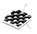
- the single figure shows a perspective view of a section of the surface of a provided with recessed cups gravure mold with a ceramic surface.
- the illustrated section 1 has a gravure form a plurality of deepening wells 2.
- the distances between the individual wells are in a range of 10 to 100 ⁇ m.
- a method is proposed which ensures the required precision by the use of an exposure system or enables further refinements which make a precise control of the individual recessed wells superfluous.
- the photosensitive filling material after The exposure is rinsed out of the deepening wells and then cured only after this.
- a possible chemical system for realizing the process according to the invention consists in the use of a dissolved in N-methylpyrrolidone vinyl chloride copolymer as the primer layer-forming liquid.
- an adhesion-promoting layer produced in this way can be detached from the ceramic surface of the intaglio printing form by soaking the basically porous ceramic base material of the intaglio printing plate with N-methylpyrrolidone, whereupon the adhesion-promoting layer is detached also adhering to the bonding layer filler is replaced with and thus the gravure form is deleted.
- the porosity of the ceramic base material of the gravure mold supports, since this allows diffusion of the solvent under the surface.
- an adhesion-promoting layer made of polyvinyl chloride ensures that it is not attacked by the solvents used for printing inks.
Landscapes
- Engineering & Computer Science (AREA)
- Manufacturing & Machinery (AREA)
- Printing Plates And Materials Therefor (AREA)
- Manufacture Or Reproduction Of Printing Formes (AREA)
- Application Of Or Painting With Fluid Materials (AREA)
- Printing Methods (AREA)
Abstract
Description
Die Erfindung betrifft ein Verfahren zur Herstellung von Tiefdruckformen, bei welchem auf der Oberfläche einer Tiefdruckform mit keramischer Oberfläche vorgesehene vertiefende Näpfchen zumindest teilweise mit einem Füllmaterial für den Druckvorgang dauerhaft gefüllt werden, die Oberfläche vor dem Aufbringen des Füllmaterials mit einer benetzenden, verfestigbaren und im verfestigten Zustand ablösbaren Flüssigkeit zur Bildung einer Haftvermittlungsschicht getränkt wird und nach dem Abschluss des Druckvorgangs das Füllmaterial und die Haftvermittlungsschicht durch Ablösen der Haftvermittlungsschicht von der Oberfläche der Tiefdruckform abgelöst wird.The invention relates to a process for the production of intaglio printing forms, wherein provided on the surface of a gravure mold with ceramic surface deepening wells are at least partially permanently filled with a filling material for the printing process, the surface before applying the filler with a wetting, solidifiable and solidified Is soaked state releasable liquid to form an adhesion-promoting layer and after completion of the printing process, the filler material and the adhesion-promoting layer is detached by detaching the adhesion-promoting layer from the surface of the intaglio printing plate.
Ein derartiges Verfahren zur Herstellung von Tiefdruckformen ist beispielsweise aus der WO 03/041961 A1 bekannt. Mit diesem bekannten Verfahren wird die Möglichkeit geschaffen, unter Verwendung einer auf der Oberfläche im Wesentlichen gleichmäßig mit vertiefenden Näpfchen versehenen keramischen Tiefdruckform variabel und einfach löschbar Tiefdruckformen zur Herstellung beliebiger Druckbilder herzustellen. Die hiermit gegenüber der konventionellen Herstellung von Tiefdruckformen erzielten Vorteile sind erheblich.Such a method for producing intaglio printing forms is known, for example, from WO 03/041961 A1. With this known method, the possibility is created, using a ceramic gravure mold provided on the surface substantially uniformly with deepening cups, to produce rotogravure printing forms for the production of any desired print images in a variably and easily erasable manner. The advantages compared with the conventional production of intaglio printing dies are considerable.
Bei dem aus der WO 03/041961 A1 bekannten Verfahren wird das Füllmaterial mit Hilfe einer Inkjet-Technik in die vertiefenden Näpfchen eingebracht. Diese Methode zur Füllung der vertiefenden Näpfchen mit einem Füllmaterial ist dahingehend problematisch, dass sie vergleichsweise langsam ist und im Hinblick auf die Präzision des Aufbringens des Füllmaterials verbesserungswürdig ist.In the method known from WO 03/041961 A1, the filling material is introduced into the recessed wells by means of an inkjet technique. This method of filling the deepening wells with a filling material is problematic in that it is comparatively slow and may be improved in terms of the precision of application of the filling material.
Ausgehend von dem zuvor beschriebenen Stand der Technik liegt der vorliegenden Erfindung die Aufgabe zu Grunde, ein Verfahren zur Herstellung von Tiefdruckformen zur Verfügung zu stellen, welches die Herstellung einfach löschbarer, hochvariabler Tiefdruckformen mit hoher Geschwindigkeit und Präzision gewährleistet.Based on the prior art described above, the object of the present invention is to provide a method for the production of intaglio printing forms, which ensures the production of easily erasable, highly variable intaglio printing forms with high speed and precision.
Die zuvor hergeleitete und aufgezeigte Aufgabe wird durch den Gegenstand von vorliegendem Anspruch 1 gelöst.The previously derived and indicated object is achieved by the subject matter of the present claim 1.
Durch den Einsatz an sich bekannter Belichtungs- und Entwicklungssysteme zur Strukturierung des auf eine im Wesentlichen gleichmäßig mit vertiefenden Näpfchen versehene keramische Tiefdruckform aufgebrachten Füllmaterials wird eine hochpräzise Herstellung von variablen Tiefdruckformen mit hoher Geschwindigkeit gewährleistet. Die EP 0 953 877 A1 beschreibt eine Belichtungsvorrichtung zur Strukturierung des Füllmaterials.The use of per se known exposure and development systems for structuring the applied to a substantially uniformly deepened wells ceramic gravure mold filling material ensures a high-precision production of variable gravure forms at high speed. EP 0 953 877 A1 describes an exposure device for structuring the filling material.
Eine erste vorteilhafte Ausgestaltung erfährt das erfindungsgemäße Verfahren dadurch, dass die Belichtung mit Hilfe eines oder mehrerer elektronisch gesteuerter Lichtstrahlen erfolgt. Aufgrund der die vertiefenden Näpfchen auf der Oberfläche der keramischen Tiefdruckform bildenden kleinen Strukturen ist eine Belichtung beispielsweise über aufgelegte Masken regelmäßig nicht hinreichend präzise, um befriedigende Ergebnisse zu liefern. Dem kann durch den Einsatz von elektronisch gesteuerten Lichtstrahlen, insbesondere Laserstrahlen begegnet werden.A first advantageous embodiment undergoes the method according to the invention in that the exposure takes place with the aid of one or more electronically controlled light beams. Due to the small structures forming the recessed wells on the surface of the ceramic gravure mold, exposure is involved For example, over-laid masks regularly not sufficiently precise to provide satisfactory results. This can be countered by the use of electronically controlled light beams, in particular laser beams.
Die auf der Oberfläche der keramischen Tiefdruckformen herzustellenden mikroskopischen Strukturen zur Erzeugung der vertiefenden Näpfchen sind nur mit einer begrenzten Präzision herstellbar. Diese begrenzte Präzision resultiert aus dem Gravurprozess zur Herstellung der Roh-Tiefdruckform. Hierbei kann aufgrund von mikroskopischen Materialinhomogenitäten und aufgrund des nur begrenzt steuerbaren thermischen Ablationsprozess nicht mit der beispielsweise bei der Herstellung von Drucksieben gewohnten relativen Präzision gewährleistet werden, dass die vertiefenden Näpfchen an einer fest vorgegebenen Position entstehen. Darüber hinaus führt die Größenordnung der Abmessungen, in der die vertiefenden Näpfchen hergestellt werden, auch dazu, dass die Positionsbestimmung eines bestimmten vertiefenden Näpfchens relativ zu Referenzpositionsmarken aufgrund mangelnder mechanischer Präzision schwer möglich ist.The microscopic structures to be produced on the surface of the ceramic intaglio printing plates for producing the deepening cells can only be produced with limited precision. This limited precision results from the engraving process for producing the raw gravure form. In this case, due to microscopic material inhomogeneities and due to the limited controllable thermal ablation process can not be guaranteed with the usual for example in the production of printing screens relative precision that the deepening wells arise at a fixed position. Moreover, the magnitude of the dimensions in which the recessed wells are made also results in the difficulty of determining the position of a particular indenting well relative to reference position indicia due to lack of mechanical precision.
Die zuvor beschriebene Problematik bei der Bestimmung der exakten Position der vertiefenden Näpfchen kann dadurch vermieden werden, dass das lichtempfindliche Füllmaterial lediglich eine Füllung der vertiefenden Näpfchen gewährleistend aufgebracht wird. Dadurch, dass vor dem Entwickeln und Belichten das lichtempfindliche Füllmaterial lediglich in die vertiefenden Näpfchen gefüllt wird, ist gewährleistet, dass auch eine relativ zu den vertiefenden Näpfchen unpräzise Belichtung nicht dazu führt, dass auf den zwischen den vertiefenden Näpfchen angeordneten Stegen belichtete Bereiche des Füllmaterials entstehen, die nach einer Entwicklung und eventuellen Aushärtung zu Problemen während des Druckvorgangs führen würden. Bei der Verwirklichung des beschriebenen Verfahrens welches nicht gemäß Anspruch 1 ist, ist also gewährleistet, dass die Belichtung mit üblicher Präzision erfolgen kann, ohne dass Nachteile in Kauf zu nehmen wären. Da sich bei diesem Verfahren auf den Stegen zwischen den vertiefenden Näpfchen kein lichtempfindliches Füllmaterial befindet, kann dieses selbstverständlich auch nicht belichtet und ausgehärtet werden.The problem described above in the determination of the exact position of the recessed wells can be avoided by applying the photosensitive filling material only a filling of the deepening wells. The fact that prior to developing and exposing the photosensitive filling material is only filled in the deepening wells, it is ensured that even a relative to the deepening wells imprecise exposure does not lead to that between the deepening Cups arranged webs arise exposed areas of the filling material, which would lead to problems during the printing process after development and eventual curing. In the realization of the described method which is not according to claim 1, it is thus ensured that the exposure can be carried out with customary precision without disadvantages being incurred. Since there is no photosensitive filling material in this method on the webs between the recessed wells, this can of course not be exposed and cured.
Bei dem soeben beschriebenen Verfahren wird vorteilhaft das lichtempfindliche Füllmaterial nach einem im Wesentlichen flächendeckenden Auftrag vor dem Belichten und/oder dem Entwickeln abgerakelt. Hierdurch wird auf besonders einfache Art und Weise gewährleistet, dass einerseits die vertiefenden Näpfchen vor dem Belichten flächendeckend gefüllt werden und andererseits die zwischen den vertiefenden Näpfchen vorgesehenen Stege nach dem Abrakeln frei von dem lichtempfindlichen Füllmaterial sind. Erfindungsgemäß wird die oben beschriebene Problematik bei Bestimmung der exakten Position der vertiefenden Näpfchen dadurch gelöst, dass vor oder während des Belichtens die exakte Position der vertiefenden Näpfchen auf der Oberfläche der Tiefdruckform ermittelt wird und die Belichtung auf Grundlage der ermittelten Positionen und des Druckbildes exakt innerhalb definierter vertiefender Näpfchen erfolgt. Die zur Verwirklichung dieser Ausgestaltung erforderliche Positionsbestimmung kann beispielsweise mit Hilfe optischer Sensoren gewährleistet werden.In the method just described, the photosensitive filling material is advantageously doctored off after an essentially blanket application before exposure and / or development. As a result, it is ensured in a particularly simple manner that, on the one hand, the deepening wells are blanket-filled before exposure, and, on the other hand, the webs provided between the deepening wells are free from the light-sensitive filling material after being doctored off. According to the invention, the problem described above in determining the exact position of the recessed wells is achieved by determining the exact position of the recessed wells on the surface of the gravure form before or during the exposure and the exposure based on the determined positions and the print image exactly within defined deepening wells done. The position determination required for the realization of this embodiment can be ensured, for example, with the aid of optical sensors.
Gemäß einer, eventuell kumulativ einsetzbaren Ausgestaltung wird die oben beschriebene Problematik dadurch entschärft, dass bei der Belichtung und Entwicklung außerhalb der vertiefenden Näpfchen entstehende, mit Füllmaterial belegte Bereiche von dem Füllmaterial durch ein materialabhebendes Verfahren befreit werden. Bei den materialabhebenden Verfahren kann es sich beispielsweise um eine Politur oder ein eventuell thermisch unterstütztes spanabhebendes Verfahren handeln.According to one, possibly cumulatively applicable embodiment, the problem described above is alleviated by the fact that in the exposure and development outside of the recessed wells resulting, filled with filling material areas are freed from the filler by a material-removing process. The material-removing process may be, for example, a polish or a possibly thermally assisted machining process.
Schließlich betrifft die Erfindung eine Vorrichtung zur Verwirklichung eines erfindungsgemäßen Verfahren.Finally, the invention relates to an apparatus for realizing a method according to the invention.
Es gibt nun eine Vielzahl von Möglichkeiten, dass zuvor beschriebene Verfahren zur Herstellung von Tiefdruckformen bzw. eine Vorrichtung zur Verwirklichung eines derartigen Verfahrens auszugestalten und weiterzubilden. Hierzu wird einerseits verwiesen auf die weitere Beschreibung in Verbindung mit der Zeichnung und andererseits auf die dem Patentanspruch 1 nachgeordneten Patentansprüche.There are now a large number of possibilities for designing and developing the previously described method for the production of intaglio printing plates or a device for realizing such a method. For this purpose, reference is made, on the one hand, to the further description in conjunction with the drawing and, on the other hand, to the claims subordinate to patent claim 1.
In der Zeichnung zeigt die einzige Figur eine perspektivische Aufnahme eines Ausschnitts der Oberfläche einer mit vertiefenden Näpfchen versehenen Tiefdruckform mit keramischer Oberfläche.In the drawing, the single figure shows a perspective view of a section of the surface of a provided with recessed cups gravure mold with a ceramic surface.
Wie aus der einzigen Figur ersichtlich ist, weist der dargestellte Ausschnitt 1 eine Tiefdruckform eine Vielzahl von vertiefenden Näpfchen 2 auf. Die Abstände zwischen den einzelnen Näpfchen liegen dabei in einem Bereich von 10 bis 100 µm.As can be seen from the single figure, the illustrated section 1 has a gravure form a plurality of deepening
Bereits aus der Darstellung in der einzigen Figur ist ersichtlich, dass gewisse Unregelmäßigkeiten in der Positionierung der vertiefenden Näpfchen vorhanden sind. Diese verstärken sich bei der Betrachtung deutlich größerer Bereiche, z.B. auf der Oberfläche von Tiefdruckwalzen mit Längen von etwa einem bis drei Metern.It can already be seen from the illustration in the single figure that certain irregularities in the positioning of the recessed wells are present. These increase when considering significantly larger areas, e.g. on the surface of gravure rolls with lengths of about one to three meters.
Weiter ist aus dem in der einzigen Figur angedeuteten Tiefenprofil der vertiefenden Näpfchen 2 ersichtlich, dass diese keine homogene Tiefenstruktur aufweisen.Furthermore, it can be seen from the depth profile of the deepening
Im Ergebnis wird anhand der Darstellung in der einzigen Figur der Zeichnung deutlich, dass eine auch teilweise Einzelbefüllung der vertiefenden Näpfchen mit Füllmaterial eine hochpräzise Steuerung erfordert. Eine derart präzise Steuerung des Auftrages eines Materials auf Druckformen beliebiger Art an eine auf der Druckform bereits vorgesehene Grundstruktur war im Stand der Technik bislang nicht erforderlich. Entweder sind die aus dem Stand der Technik - beispielsweise im Bereich der Siebdruckformen - bekannten vorgegebenen Strukturen von deutlich größeren Dimensionen oder es sind keine Strukturen auf der Roh-Druckform vorhanden, die in Deckung mit dem Druckbild gebracht werden müssen, vorhanden.As a result, it becomes clear from the illustration in the single figure of the drawing that partial filling of the deepening wells with filling material also requires highly precise control. Such a precise control of the order of a material on printing forms of any kind to an already provided on the printing plate basic structure was not required in the prior art. Either the known structures known from the prior art-for example in the field of screen printing forms-are of significantly larger dimensions or there are no structures on the raw printing form which must be brought into coincidence with the printed image.
Erfindungsgemäß wird ein Verfahren vorgeschlagen, welches durch die Verwendung eines Belichtungssystems die geforderte Präzision gewährleistet bzw. weitere Ausgestaltungen ermöglicht, die eine präzise Ansteuerung der einzelnen vertiefenden Näpfchen überflüssig macht.According to the invention, a method is proposed which ensures the required precision by the use of an exposure system or enables further refinements which make a precise control of the individual recessed wells superfluous.
Der Vollständigkeit halber soll hier noch erwähnt werden, dass in der Regel das lichtempfindliche Füllmaterial nach der Belichtung aus den vertiefenden Näpfchen ausgespült wird und erst im Anschluss hieran abschließend ausgehärtet wird.For the sake of completeness, it should be mentioned here that, as a rule, the photosensitive filling material after The exposure is rinsed out of the deepening wells and then cured only after this.
Ein mögliches chemisches System zur Verwirklichung des erfindungsgemäßen Verfahrens besteht in der Verwendung eines in N-Methylpyrrolidon gelösten Vinylchlorid-Copolimers als die Haftvermittlungsschicht bildender Flüssigkeit. Eine derart hergestellte Haftvermittlungsschicht kann nach dem Auftrag und der Strukturierung eines geeigneten Füllmaterials und dem anschließenden Druckvorgang dadurch von der keramischen Oberfläche der Tiefdruckform abgelöst werden, dass das grundsätzlich poröse keramische Grundmaterial der Tiefdruckform mit N-Methylpyrrolidon getränkt wird, woraufhin sich die Haftvermittlungsschicht ablöst, wodurch auch das an der Haftvermittlungsschicht anhaftende Füllmaterial mit abgelöst wird und somit die Tiefdruckform gelöscht wird.A possible chemical system for realizing the process according to the invention consists in the use of a dissolved in N-methylpyrrolidone vinyl chloride copolymer as the primer layer-forming liquid. After the application and structuring of a suitable filling material and the subsequent printing process, an adhesion-promoting layer produced in this way can be detached from the ceramic surface of the intaglio printing form by soaking the basically porous ceramic base material of the intaglio printing plate with N-methylpyrrolidone, whereupon the adhesion-promoting layer is detached also adhering to the bonding layer filler is replaced with and thus the gravure form is deleted.
Dabei wirkt die Porösität des keramischen Grundmaterials der Tiefdruckform unterstützend, da diese eine Diffusion des Lösungsmittels unter die Oberfläche ermöglicht.In this case, the porosity of the ceramic base material of the gravure mold supports, since this allows diffusion of the solvent under the surface.
Außerdem ist durch den Einsatz einer aus Polyvinylchlorid hergestellten Haftvermittlungsschicht sichergestellt, dass diese nicht durch die für Druckfarben verwendeten Lösungsmittel angegriffen wird.In addition, the use of an adhesion-promoting layer made of polyvinyl chloride ensures that it is not attacked by the solvents used for printing inks.
Claims (4)
- A method for producing gravure printing plates, in which recessed cells with a ceramic surface on the surface of a gravure printing plate are permanently at least partly filled with a filling material for the printing process, in which the surface is saturated with a moistening liquid that is capable of solidifying and being detached in the solid state to form an adhesion enhancing film before the application of the filling material, and in which the filling material and the adhesion enhancing film are detached after the printing process is completed by detaching the adhesion enhancing film from the from the surface of the rotogravure plate,
characterised in that
a photosensitive filling material is applied and after its application the filling material is structured by exposure to light and development to guarantee a predefined fill level in the recessed cells, and the exact positions of the recessed cells on the surface of the gravure printing plate are determined before or during the exposure to light, and the light exposure is effected precisely within defined recessed cells on the basis of the calculated positions. - The method in accordance with claim 1,
characterised in that
the exposure to light is effected via one or more electronically controlled light beams. - The method in accordance with either of claims 1 or 2,
characterised in that
areas created material during the exposure to light and development outside of the recessed cells that are occupied with filling undergo a material removing process for removing the filling material. - A device for performing a method in accordance with any of claims 1 to 3.
Priority Applications (3)
| Application Number | Priority Date | Filing Date | Title |
|---|---|---|---|
| DE502004001157T DE502004001157D1 (en) | 2004-04-22 | 2004-04-22 | Method and device for the production of gravure printing forms |
| EP04009523A EP1588846B1 (en) | 2004-04-22 | 2004-04-22 | Method and device for producing an offset printing plate |
| AT04009523T ATE335603T1 (en) | 2004-04-22 | 2004-04-22 | METHOD AND DEVICE FOR PRODUCING GRAPH PRINTING FORMS |
Applications Claiming Priority (1)
| Application Number | Priority Date | Filing Date | Title |
|---|---|---|---|
| EP04009523A EP1588846B1 (en) | 2004-04-22 | 2004-04-22 | Method and device for producing an offset printing plate |
Publications (2)
| Publication Number | Publication Date |
|---|---|
| EP1588846A1 EP1588846A1 (en) | 2005-10-26 |
| EP1588846B1 true EP1588846B1 (en) | 2006-08-09 |
Family
ID=34924690
Family Applications (1)
| Application Number | Title | Priority Date | Filing Date |
|---|---|---|---|
| EP04009523A Expired - Lifetime EP1588846B1 (en) | 2004-04-22 | 2004-04-22 | Method and device for producing an offset printing plate |
Country Status (3)
| Country | Link |
|---|---|
| EP (1) | EP1588846B1 (en) |
| AT (1) | ATE335603T1 (en) |
| DE (1) | DE502004001157D1 (en) |
Family Cites Families (4)
| Publication number | Priority date | Publication date | Assignee | Title |
|---|---|---|---|---|
| DE19503951C2 (en) * | 1995-02-07 | 1998-04-09 | Roland Man Druckmasch | Method and device for gravure printing |
| DE59907981D1 (en) * | 1998-04-29 | 2004-01-22 | Cst Gmbh | Process for the production of screen printing forms and an exposure device therefor |
| DE10115434A1 (en) * | 2001-03-29 | 2002-10-10 | Huber Fa Michael Muenchen | Prepolymer and anilox roller filling material for variable-depth laser ablation |
| ES2303567T3 (en) * | 2001-11-17 | 2008-08-16 | Erhard Lorch | PROCEDURE FOR THE MANUFACTURE OF MOLES OF HUECOGRABADO, MOLDS OF HUECOGRABADO AND ITS USE. |
-
2004
- 2004-04-22 AT AT04009523T patent/ATE335603T1/en not_active IP Right Cessation
- 2004-04-22 EP EP04009523A patent/EP1588846B1/en not_active Expired - Lifetime
- 2004-04-22 DE DE502004001157T patent/DE502004001157D1/en not_active Expired - Lifetime
Also Published As
| Publication number | Publication date |
|---|---|
| DE502004001157D1 (en) | 2006-09-21 |
| ATE335603T1 (en) | 2006-09-15 |
| EP1588846A1 (en) | 2005-10-26 |
Similar Documents
| Publication | Publication Date | Title |
|---|---|---|
| DE60019742T2 (en) | METHOD FOR PRODUCING A PATTERNED CONCRETE SURFACE | |
| DE3587656T2 (en) | Stereolithographic device and method for producing three-dimensional objects. | |
| DE3222680C2 (en) | Ink jet head and process for its manufacture | |
| DE102006058560A1 (en) | A method of forming high resolution structures of desired thickness or high aspect ratio by means of a dry film resist | |
| DE4442235A1 (en) | Use of organically modified ceramic in coating for printing substrate | |
| DE69908261T2 (en) | LITHOGRAPHIC PROCESS WITH LAYERS CONTAINING INORGANIC-ORGANIC MIXTURES | |
| DE10360108A1 (en) | Printing plate, for the printing cylinder of an offset printing press has a surface of a shape memory material which is subjected to two different temperatures to give an erasure for repeated use | |
| DE102015015629A1 (en) | Method for producing a casting mold | |
| EP1888321B1 (en) | Process for producing an object having at least two moving parts | |
| DE2918076A1 (en) | Gravure printing raw plate and process for the manufacture thereof | |
| DE2531947C3 (en) | Process for producing a stitch printing plate that can be used without wiping, printing plate produced according to this process and its application | |
| DE2214728C3 (en) | Process for the direct photomechanical production of screen printing forms | |
| DE102014007562A1 (en) | Apparatus and method for the production of three-dimensional molded parts with integrated pattern structure by additive manufacturing | |
| EP1456030B1 (en) | Method for producing rotogravure forms, rotogravure forms and the use thereof | |
| DE102004041610B4 (en) | Process for producing a lithographic printing plate | |
| EP1588846A1 (en) | Method for producing an offset printing plate | |
| EP1040916B1 (en) | Method and apparatus for producing a printing plate | |
| DE102007001953B4 (en) | Microstructured film, process for its preparation and its use | |
| DE69835744T2 (en) | PRESSURE SLEEVE AND METHOD FOR PRODUCING A PRESSURE SLEEVE WITH DIGITALLY CONTROLLED PHOTOPOLYMERIZATION | |
| EP3159740B1 (en) | Method for generative production of relief printing plates | |
| DE102019123128B4 (en) | 3D screen printing system and 3D screen printing process for producing a shaped body | |
| DE102014111559B4 (en) | Process for the production of layer sequences and moldings from a number of layers | |
| EP1876022A2 (en) | Anilox roll and flexographic printing | |
| DE102012018635A1 (en) | Method for producing three dimensional structure of integrated circuit, involves introducing coarse structure of three dimensional structure by unit of two dimensional surface in lithography of lithography sensitive material | |
| EP3482937A1 (en) | Method for structuring a surface, gravure printing form or embossing tool and use |
Legal Events
| Date | Code | Title | Description |
|---|---|---|---|
| PUAI | Public reference made under article 153(3) epc to a published international application that has entered the european phase |
Free format text: ORIGINAL CODE: 0009012 |
|
| AK | Designated contracting states |
Kind code of ref document: A1 Designated state(s): AT BE BG CH CY CZ DE DK EE ES FI FR GB GR HU IE IT LI LU MC NL PL PT RO SE SI SK TR |
|
| AX | Request for extension of the european patent |
Extension state: AL HR LT LV MK |
|
| 17P | Request for examination filed |
Effective date: 20051014 |
|
| GRAP | Despatch of communication of intention to grant a patent |
Free format text: ORIGINAL CODE: EPIDOSNIGR1 |
|
| RTI1 | Title (correction) |
Free format text: METHOD AND DEVICE FOR PRODUCING AN OFFSET PRINTING PLATE |
|
| GRAS | Grant fee paid |
Free format text: ORIGINAL CODE: EPIDOSNIGR3 |
|
| AKX | Designation fees paid |
Designated state(s): AT BE BG CH CY CZ DE DK EE ES FI FR GB GR HU IE IT LI LU MC NL PL PT RO SE SI SK TR |
|
| GRAA | (expected) grant |
Free format text: ORIGINAL CODE: 0009210 |
|
| RIN1 | Information on inventor provided before grant (corrected) |
Inventor name: KLENK, DIETER Inventor name: KESPER, PETER |
|
| AK | Designated contracting states |
Kind code of ref document: B1 Designated state(s): AT BE BG CH CY CZ DE DK EE ES FI FR GB GR HU IE IT LI LU MC NL PL PT RO SE SI SK TR |
|
| PG25 | Lapsed in a contracting state [announced via postgrant information from national office to epo] |
Ref country code: IT Free format text: LAPSE BECAUSE OF FAILURE TO SUBMIT A TRANSLATION OF THE DESCRIPTION OR TO PAY THE FEE WITHIN THE PRESCRIBED TIME-LIMIT;WARNING: LAPSES OF ITALIAN PATENTS WITH EFFECTIVE DATE BEFORE 2007 MAY HAVE OCCURRED AT ANY TIME BEFORE 2007. THE CORRECT EFFECTIVE DATE MAY BE DIFFERENT FROM THE ONE RECORDED. Effective date: 20060809 Ref country code: SI Free format text: LAPSE BECAUSE OF FAILURE TO SUBMIT A TRANSLATION OF THE DESCRIPTION OR TO PAY THE FEE WITHIN THE PRESCRIBED TIME-LIMIT Effective date: 20060809 Ref country code: IE Free format text: LAPSE BECAUSE OF FAILURE TO SUBMIT A TRANSLATION OF THE DESCRIPTION OR TO PAY THE FEE WITHIN THE PRESCRIBED TIME-LIMIT Effective date: 20060809 Ref country code: SK Free format text: LAPSE BECAUSE OF FAILURE TO SUBMIT A TRANSLATION OF THE DESCRIPTION OR TO PAY THE FEE WITHIN THE PRESCRIBED TIME-LIMIT Effective date: 20060809 Ref country code: CZ Free format text: LAPSE BECAUSE OF FAILURE TO SUBMIT A TRANSLATION OF THE DESCRIPTION OR TO PAY THE FEE WITHIN THE PRESCRIBED TIME-LIMIT Effective date: 20060809 Ref country code: PL Free format text: LAPSE BECAUSE OF FAILURE TO SUBMIT A TRANSLATION OF THE DESCRIPTION OR TO PAY THE FEE WITHIN THE PRESCRIBED TIME-LIMIT Effective date: 20060809 Ref country code: RO Free format text: LAPSE BECAUSE OF FAILURE TO SUBMIT A TRANSLATION OF THE DESCRIPTION OR TO PAY THE FEE WITHIN THE PRESCRIBED TIME-LIMIT Effective date: 20060809 Ref country code: NL Free format text: LAPSE BECAUSE OF FAILURE TO SUBMIT A TRANSLATION OF THE DESCRIPTION OR TO PAY THE FEE WITHIN THE PRESCRIBED TIME-LIMIT Effective date: 20060809 Ref country code: FI Free format text: LAPSE BECAUSE OF FAILURE TO SUBMIT A TRANSLATION OF THE DESCRIPTION OR TO PAY THE FEE WITHIN THE PRESCRIBED TIME-LIMIT Effective date: 20060809 |
|
| REG | Reference to a national code |
Ref country code: GB Ref legal event code: FG4D Free format text: NOT ENGLISH |
|
| REG | Reference to a national code |
Ref country code: CH Ref legal event code: EP |
|
| REG | Reference to a national code |
Ref country code: IE Ref legal event code: FG4D Free format text: LANGUAGE OF EP DOCUMENT: GERMAN |
|
| REF | Corresponds to: |
Ref document number: 502004001157 Country of ref document: DE Date of ref document: 20060921 Kind code of ref document: P |
|
| REG | Reference to a national code |
Ref country code: CH Ref legal event code: NV Representative=s name: SCHMAUDER & PARTNER AG PATENTANWALTSBUERO |
|
| PG25 | Lapsed in a contracting state [announced via postgrant information from national office to epo] |
Ref country code: SE Free format text: LAPSE BECAUSE OF FAILURE TO SUBMIT A TRANSLATION OF THE DESCRIPTION OR TO PAY THE FEE WITHIN THE PRESCRIBED TIME-LIMIT Effective date: 20061109 Ref country code: DK Free format text: LAPSE BECAUSE OF FAILURE TO SUBMIT A TRANSLATION OF THE DESCRIPTION OR TO PAY THE FEE WITHIN THE PRESCRIBED TIME-LIMIT Effective date: 20061109 Ref country code: BG Free format text: LAPSE BECAUSE OF FAILURE TO SUBMIT A TRANSLATION OF THE DESCRIPTION OR TO PAY THE FEE WITHIN THE PRESCRIBED TIME-LIMIT Effective date: 20061109 |
|
| PG25 | Lapsed in a contracting state [announced via postgrant information from national office to epo] |
Ref country code: ES Free format text: LAPSE BECAUSE OF FAILURE TO SUBMIT A TRANSLATION OF THE DESCRIPTION OR TO PAY THE FEE WITHIN THE PRESCRIBED TIME-LIMIT Effective date: 20061120 |
|
| GBT | Gb: translation of ep patent filed (gb section 77(6)(a)/1977) |
Effective date: 20061030 |
|
| PG25 | Lapsed in a contracting state [announced via postgrant information from national office to epo] |
Ref country code: PT Free format text: LAPSE BECAUSE OF FAILURE TO SUBMIT A TRANSLATION OF THE DESCRIPTION OR TO PAY THE FEE WITHIN THE PRESCRIBED TIME-LIMIT Effective date: 20070109 |
|
| NLV1 | Nl: lapsed or annulled due to failure to fulfill the requirements of art. 29p and 29m of the patents act | ||
| REG | Reference to a national code |
Ref country code: IE Ref legal event code: FD4D |
|
| ET | Fr: translation filed | ||
| PLBE | No opposition filed within time limit |
Free format text: ORIGINAL CODE: 0009261 |
|
| STAA | Information on the status of an ep patent application or granted ep patent |
Free format text: STATUS: NO OPPOSITION FILED WITHIN TIME LIMIT |
|
| 26N | No opposition filed |
Effective date: 20070510 |
|
| PG25 | Lapsed in a contracting state [announced via postgrant information from national office to epo] |
Ref country code: GR Free format text: LAPSE BECAUSE OF FAILURE TO SUBMIT A TRANSLATION OF THE DESCRIPTION OR TO PAY THE FEE WITHIN THE PRESCRIBED TIME-LIMIT Effective date: 20061110 |
|
| PG25 | Lapsed in a contracting state [announced via postgrant information from national office to epo] |
Ref country code: EE Free format text: LAPSE BECAUSE OF FAILURE TO SUBMIT A TRANSLATION OF THE DESCRIPTION OR TO PAY THE FEE WITHIN THE PRESCRIBED TIME-LIMIT Effective date: 20060809 |
|
| PGRI | Patent reinstated in contracting state [announced from national office to epo] |
Ref country code: IT Effective date: 20080601 |
|
| PG25 | Lapsed in a contracting state [announced via postgrant information from national office to epo] |
Ref country code: MC Free format text: LAPSE BECAUSE OF NON-PAYMENT OF DUE FEES Effective date: 20070430 |
|
| PGFP | Annual fee paid to national office [announced via postgrant information from national office to epo] |
Ref country code: GB Payment date: 20090224 Year of fee payment: 6 |
|
| REG | Reference to a national code |
Ref country code: CH Ref legal event code: PCAR Free format text: SCHMAUDER & PARTNER AG PATENT- UND MARKENANWAELTE VSP;ZWAENGIWEG 7;8038 ZUERICH (CH) |
|
| PG25 | Lapsed in a contracting state [announced via postgrant information from national office to epo] |
Ref country code: CY Free format text: LAPSE BECAUSE OF FAILURE TO SUBMIT A TRANSLATION OF THE DESCRIPTION OR TO PAY THE FEE WITHIN THE PRESCRIBED TIME-LIMIT Effective date: 20060809 Ref country code: LU Free format text: LAPSE BECAUSE OF NON-PAYMENT OF DUE FEES Effective date: 20070422 |
|
| PGFP | Annual fee paid to national office [announced via postgrant information from national office to epo] |
Ref country code: AT Payment date: 20090428 Year of fee payment: 6 Ref country code: FR Payment date: 20090422 Year of fee payment: 6 Ref country code: IT Payment date: 20090428 Year of fee payment: 6 |
|
| PG25 | Lapsed in a contracting state [announced via postgrant information from national office to epo] |
Ref country code: TR Free format text: LAPSE BECAUSE OF FAILURE TO SUBMIT A TRANSLATION OF THE DESCRIPTION OR TO PAY THE FEE WITHIN THE PRESCRIBED TIME-LIMIT Effective date: 20060809 Ref country code: HU Free format text: LAPSE BECAUSE OF FAILURE TO SUBMIT A TRANSLATION OF THE DESCRIPTION OR TO PAY THE FEE WITHIN THE PRESCRIBED TIME-LIMIT Effective date: 20070210 |
|
| PGFP | Annual fee paid to national office [announced via postgrant information from national office to epo] |
Ref country code: BE Payment date: 20090528 Year of fee payment: 6 |
|
| PGFP | Annual fee paid to national office [announced via postgrant information from national office to epo] |
Ref country code: CH Payment date: 20090505 Year of fee payment: 6 |
|
| PGFP | Annual fee paid to national office [announced via postgrant information from national office to epo] |
Ref country code: DE Payment date: 20100422 Year of fee payment: 7 |
|
| BERE | Be: lapsed |
Owner name: *CST G.M.B.H. Effective date: 20100430 |
|
| REG | Reference to a national code |
Ref country code: CH Ref legal event code: PL |
|
| GBPC | Gb: european patent ceased through non-payment of renewal fee |
Effective date: 20100422 |
|
| REG | Reference to a national code |
Ref country code: FR Ref legal event code: ST Effective date: 20101230 |
|
| PG25 | Lapsed in a contracting state [announced via postgrant information from national office to epo] |
Ref country code: AT Free format text: LAPSE BECAUSE OF NON-PAYMENT OF DUE FEES Effective date: 20100422 |
|
| PG25 | Lapsed in a contracting state [announced via postgrant information from national office to epo] |
Ref country code: LI Free format text: LAPSE BECAUSE OF NON-PAYMENT OF DUE FEES Effective date: 20100430 Ref country code: CH Free format text: LAPSE BECAUSE OF NON-PAYMENT OF DUE FEES Effective date: 20100430 |
|
| PG25 | Lapsed in a contracting state [announced via postgrant information from national office to epo] |
Ref country code: GB Free format text: LAPSE BECAUSE OF NON-PAYMENT OF DUE FEES Effective date: 20100422 Ref country code: IT Free format text: LAPSE BECAUSE OF NON-PAYMENT OF DUE FEES Effective date: 20100422 Ref country code: BE Free format text: LAPSE BECAUSE OF NON-PAYMENT OF DUE FEES Effective date: 20100430 |
|
| PG25 | Lapsed in a contracting state [announced via postgrant information from national office to epo] |
Ref country code: DE Free format text: LAPSE BECAUSE OF NON-PAYMENT OF DUE FEES Effective date: 20111101 |
|
| REG | Reference to a national code |
Ref country code: DE Ref legal event code: R119 Ref document number: 502004001157 Country of ref document: DE Effective date: 20111101 |
|
| PG25 | Lapsed in a contracting state [announced via postgrant information from national office to epo] |
Ref country code: FR Free format text: LAPSE BECAUSE OF NON-PAYMENT OF DUE FEES Effective date: 20100430 |