EP1588678A1 - Modular hip orthosis - Google Patents
Modular hip orthosis Download PDFInfo
- Publication number
- EP1588678A1 EP1588678A1 EP05007935A EP05007935A EP1588678A1 EP 1588678 A1 EP1588678 A1 EP 1588678A1 EP 05007935 A EP05007935 A EP 05007935A EP 05007935 A EP05007935 A EP 05007935A EP 1588678 A1 EP1588678 A1 EP 1588678A1
- Authority
- EP
- European Patent Office
- Prior art keywords
- thigh
- joint
- hip
- connecting means
- pelvic ring
- Prior art date
- Legal status (The legal status is an assumption and is not a legal conclusion. Google has not performed a legal analysis and makes no representation as to the accuracy of the status listed.)
- Granted
Links
Images


Classifications
-
- A—HUMAN NECESSITIES
- A61—MEDICAL OR VETERINARY SCIENCE; HYGIENE
- A61F—FILTERS IMPLANTABLE INTO BLOOD VESSELS; PROSTHESES; DEVICES PROVIDING PATENCY TO, OR PREVENTING COLLAPSING OF, TUBULAR STRUCTURES OF THE BODY, e.g. STENTS; ORTHOPAEDIC, NURSING OR CONTRACEPTIVE DEVICES; FOMENTATION; TREATMENT OR PROTECTION OF EYES OR EARS; BANDAGES, DRESSINGS OR ABSORBENT PADS; FIRST-AID KITS
- A61F5/00—Orthopaedic methods or devices for non-surgical treatment of bones or joints; Nursing devices; Anti-rape devices
- A61F5/01—Orthopaedic devices, e.g. splints, casts or braces
- A61F5/0193—Apparatus specially adapted for treating hip dislocation; Abduction splints
-
- A—HUMAN NECESSITIES
- A61—MEDICAL OR VETERINARY SCIENCE; HYGIENE
- A61F—FILTERS IMPLANTABLE INTO BLOOD VESSELS; PROSTHESES; DEVICES PROVIDING PATENCY TO, OR PREVENTING COLLAPSING OF, TUBULAR STRUCTURES OF THE BODY, e.g. STENTS; ORTHOPAEDIC, NURSING OR CONTRACEPTIVE DEVICES; FOMENTATION; TREATMENT OR PROTECTION OF EYES OR EARS; BANDAGES, DRESSINGS OR ABSORBENT PADS; FIRST-AID KITS
- A61F5/00—Orthopaedic methods or devices for non-surgical treatment of bones or joints; Nursing devices; Anti-rape devices
- A61F5/01—Orthopaedic devices, e.g. splints, casts or braces
- A61F5/0102—Orthopaedic devices, e.g. splints, casts or braces specially adapted for correcting deformities of the limbs or for supporting them; Ortheses, e.g. with articulations
- A61F2005/0132—Additional features of the articulation
- A61F2005/0144—Multibar
Definitions
- the invention relates to a hip orthosis for application in the hip and a thigh of a user with an orthosis part, consisting of a pelvic ring, a femur part, a Condylenteil and connecting means with a hinge, wherein the connecting means connect the pelvic ring to the condylar part, with the femoral part either with the pelvic ring and the condyle part the connecting means is connected or a part of the connecting means is, and where the joint is a flexing of the hip joint allows.
- braces and bandages For the orthopedic treatment of a hip joint, in particular in terms of guidance and stabilization, are different braces and bandages known. These orthoses and bandages in particular then applied when an increased hip joint dislocation tendency or hip instability can be expected in a patient or present.
- Hip joint bandages are characterized by a good fit and high patient acceptance. They work through one Compression on the soft tissue mantle and stabilize the hip joint through this compression of the soft tissues. As negative on hip joint bandages However, it is considered that they are the femoral head only with little force in the acetabulum press and thereby a Risk of dislocation persists. In addition, they limit the Patients in too little in his freedom of movement, so that this his thigh and the hip joint in under orthopedic Points of view can bring undesirable positions.
- hip joint bandages An alternative to hip joint bandages are the aforementioned H Cosmetic kitesen dar. In these is one of several Components existing skeleton of the thighs in its movement guided. By an adjustable very rigid joint is the thigh placed in an abduction position and thereby the femoral head better adjusted in the acetabular cup. In addition, the Flexion in the hip joint limited by a stop.
- hip braces is by a so-called three-point principle a force exerted on the thigh by means of a femur part be, with the femur part via connecting means with a in the range the waist or the waist belt and with an over Connected to the knee Condylenteil is connected, so that the force be applied to the thigh of these components can.
- the force exerted on the thigh presses the femoral head in the acetabulum, thus preventing dislocation of the joint.
- the connecting means which the waist or hip ring with connect the condylar part, have a joint at the level of the hip joint on, which allows a flexion of the thigh.
- hip joint orthoses When A disadvantage of these hip joint orthoses is considered that the Fit is often unsatisfactory due to the rigid components and that Such hip joint orthoses in a complex manner for the patient need to be adjusted. In addition, orthoses of this type very heavy and misshapen, so they are not under the clothes of the patient can be worn. The acceptance is therefore in many patients not very high. The most serious disadvantage, however, is that they only work satisfactorily as long as the axis of the hip joint and the axis of the hinge of the hip orthosis coaxial with each other are. If the hip joint orthosis is not ideally adjusted or not Ideally, it comes to the movement of the patient to strong Strain on the hip joint, which is a dislocation of the hip joint can favor.
- the invention is based on the object, a hip orthosis available to counteract a dislocation effectively and the user regarding his freedom of movement only under orthopedic aspects limits meaningful way.
- the pelvic ring is such that it is safe and comfortable Hold on the user's pelvis. It is useful, for example a pelvic ring made of a bendable material is so that it is suitable for users with different body measurements is.
- the condyle serves to accommodate the thigh immediately above the knee. Conveniently, it has a U-shaped shape, which partially encloses the thigh from the front and sides, as well as Means that ensure a firm grip, for example in shape a closure strap, which varies according to the size of the thigh can be pulled far.
- the connecting means exist for example, one or more rails, which are preferably is about metal rails. These rails connect the Pelvic ring with the Condylenteil and allow attachment of the Femoral pressure part.
- the femur pressure part exerts pressure on the outside Thigh off and so holds the hip joint in the acetabulum.
- the force exerted by the thigh on the femur pressure part counterforce is compensated by the pelvic ring and condylar part.
- connecting means between the pelvic ring and the condylar part which consists of only one Rail
- the femur pressure part releasably connected to one of the two or both connecting rails be such that adjustability in terms of the length of the connecting means is given at the femur pressure part.
- the joint allows one Flexion of the thigh, limiting the movement in that than that these are desirable only in one orthopedic point of view Level is possible.
- the use of multiple joint axes prevents a malicious incongruity in which the axis of the hip joint and the axis of the joint of the connecting means not with each other to match. In such a case the incongruence would If a flexion of the thigh is reflected in strong forces, which act on the hip joint and could favor a dislocation.
- the use of a joint with multiple hinge axes leads that the joint automatically aligns itself so that the Swivel axis of the joint coincides with the hinge axis of the Hip joint.
- the joint is a chain joint with substantially parallel axes of articulation, the number of axes is at least two and preferably three.
- a joint is manufacturing technology easy to manufacture and has a high stability. Due to the parallel joint axes ensures that a movement of the joint can only be done in one plane.
- the essential Advantage of such a chain joint which is that automatically a congruence between the articular axis of the hip joint and The axis of the orthosis adjusts, is already in a chain joint achieved with two joints.
- a chain joint with three joints allows beyond a length adjustment of the connecting means, so that prevents the femoral pressure part and the condyle part moving relative to the thigh when the thigh is flexed becomes.
- the joint limits bending of the thigh in one or both directions at one fixed angle, forward preferably at about 60 ° to 80 °, in particular at 70 °. In this way it is achieved that no Involvement is possible, which favors a dislocation of the hip joint.
- a limitation of the angle for a backward movement is usually not mandatory. If it does, however, to a very wide flexion of the thigh comes forward, the hip joint can anatomically easier to slip out of the acetabular cup. Such a position can be achieved by an angle limitation according to the invention be prevented.
- the object underlying the invention can also by a Hip orthosis of the type mentioned are solved, the connecting means comprising, at least partially made of a resilient material, preferably made of spring steel, and made to the thigh and are bendable away from the thigh.
- Such bendable connection means allow the user to despite the effect of the firm frame of the hip orthosis, an abduction and adduction of the leg. This is special therefore desirable, since in this way a normal Walking movement of the user is possible, in which the total mass of the body of the user alternately completely on each one Leg is heavy.
- the adduction of the leg allows the user to the leg during the walking movements immediately under the center of gravity of the body, allowing a natural walking motion is possible. This is especially in terms of a balanced Strain on the user's muscles desirable.
- the connecting means with the Pelvic ring so connected that the thigh of the natural Position of the thigh is pressed outwards, preferably with a force of 10 to 30 newtons and preferably up to one Angle from 10 ° to 30 °.
- the angle, under the connecting means are connected to the pelvic ring is preferably adjustable. This can be done, for example, by means of small wedge elements be achieved, which between connecting means and pelvic ring be used. By selecting and aligning this Wedge elements can thus specifically reaches the desired abduction position become.
- the joint is in one direction perpendicular to the movement surface or parallel to a hinge axis resilient educated.
- the object underlying the invention can also by a Hip orthosis of the type mentioned solved with a bandage part be, which is preferably releasably connected to the orthosis part and that is designed so that it is at least part of the hip and of the thigh.
- Such a hip orthosis combines the advantages of a bandage with the Advantages of a stable orthosis. So is by the bandage part a Compression effect exerted on the soft tissues, leading to a stabilization of the hip joint head in the acetabulum.
- the orthosis part stabilizes the leg so that there is no dislocation.
- the Orthesis part and the bandage part are preferably from each other Separable, so they can be replaced separately.
- the orthosis part can be designed so that it with and without the bandage part is usable.
- a thigh segment of the Bandage part in particular a thigh segment on the inside of the thigh, releasably connected to the rest of the bandage, preferably by means of a zipper and / or a Velcro fastener.
- a segment of the Bandagenteils be separated separately from the main part of the bandage.
- This is convenient as it is the parts of the bandage that are on the inside of the thigh, from a hygienic point of view exposed to special loads.
- a separate Separability makes it possible to change these parts more frequently or to wash separately from the main part of the bandage.
- simple connection means with the main part of the bandage such as a zipper and / or a Velcro closure is It is possible for even people to be restricted in their freedom of movement are to remove this segment of the bandage easily and can exchange.
- the object underlying the invention can also by a Hip orthosis of the type mentioned above with adaptability to different Users are solved, which allows the connection means are changeable with respect to their length, that the connecting means with respect to their junction with the pelvic ring are adjustable and / or that the pelvic ring and the condyle part are made of flexible material are, for example, thermoplastic, and by means of elastic or adjustable Closure means to different pelvic or Knieumfnaturee are customizable.
- Such a configured hip orthosis can be used by different users be adapted without having to be replaced parts. Furthermore, it is also not necessary for users of different Stature different hip braces provide, as all the essential distinguishing features between different users through one such system can be considered individually.
- connecting means For example, a system with two metal rails serve, which are mutually displaceable and fixable with each other, so that differences in the distance between pelvis and knee are different User can be accommodated.
- expedient is also a system with two metal rails, both with the femur pressure part are connected.
- Such a system can change the Length of the connecting means provide that the metal rails fixed in different positions on the femur pressure part, for example screwed, can be.
- An adaptability regarding the Joint between the pelvic ring and connecting means is therefore expedient, since when using one and the same pelvic ring for users of different body circumference, the pelvic ring in different Dimensions include the pelvis. Will therefore be very slim Users almost completely encompass the pelvis becomes more diverent Users only a partial area, for example, three quarters of the basin includes.
- the adjustability of the connection between the pelvic ring and connecting means allows the connecting means depending on the stature of the user to adjust so that the connecting means to intersect in the joint with the hinge axis of the hip joint.
- the condyle part is related to one formed on the user horizontal transverse axis pivotable. This allows the Condylenteil depending on the thigh shape of the user. In this way will be a more convenient and tight fit guaranteed.
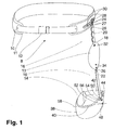
- the pelvic ring 10 consists of a flexible thermoplastic and is designed to hold the pelvis encloses a user about three quarters.
- the pelvic ring 10 is with a soft pad 11 and closing means 12 in the form of a Belt with buckle.
- the connecting means 16 consist of an upper metal rail 18, which provided with a chain joint 20 of three joints and a lower metal rail 22.
- the upper metal rail 18 is connected by means of two screws 24 with a fixing element 26, which allows the adjustable connection with the pelvic ring 10.
- the fixing element 26 has two horizontal Slotted holes 28, which a flexible screwing of the fixing element 26 allow by means of two screws 30 on the pelvic ring 10. In this way, the intersection of the pelvic ring 10 with the metal rail 18 are changed in the horizontal direction. In vertical direction is an adjustability through two slots 27 am given the upper end of the metal rail 18.
- At the bottom of the upper Metal rail 18 is connected to the femur pressure plate 13.
- the connection between the metal rail 18 and the femur pressure plate 13 is made by means of two rivets 32.
- the second metal rail closes 22 on. This is with the femur pressure plate 13 by means of two Screw 34 connected.
- the two screws 34 are arranged so that they protrude through a slot 36 in the metal rail 22 and on the opposite side to a not visible in Fig. 1 Manner are tightened.
- the length of the connecting means 16 can be changed by means of these two screws 34.
- the Condylenteil 14 consists of a plastic ring 38, which is such that it roughly shorts the user's thigh encloses three quarters. On the inside of this plastic ring 38 is a padding 40.
- the adaptability to various thigh circumferences is accomplished by means of a belt 42, the Thigh of the user at the rear of the plastic ring 38 not encompassed side of the Condylenteils 14 surrounds.
- the belt 42 is on one side by means of a Befest Trentsniets 44 with the plastic ring 38 connected. On the other hand, he is through a buckle 46 held, which is not visible in the perspective of FIG.
- the Connection between the metal rail 22 and the Condylenteil 14 is ensured by fastening means 48 which an insertion opening 50 for receiving the metal rail 22 have.
- fastening means 48 two screws 52, 54 on, which from the outside are screwed through the metal rail 22.
- the lower of these Screws 52 is thereby through a bore of the fastener 48 led.
- the upper screw 54 is formed by a circular arc segment-shaped Slot 56 led. In this way it is possible to tilt the condyle part 14 about the axis 58 by the screw 54 dissolved, the condyle portion 14 tilted and the screw 54 then is attracted again.
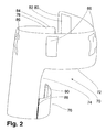
- FIG. 2 shows a bandage part 70 of a hip orthosis according to the invention from behind.
- the bandage part 70 has an upper portion 72, which encloses the hip of a user.
- a lower section 74 encloses together with a segment 76 the thigh of the User.
- the upper section 72 is closed on the rear side, while it opens on the front side in two ends 78, 80, which are connected together in the course of applying the orthosis can.
- the ends 78, 80 each have a hook-and-loop fastener 82, 84, wherein in the perspective of FIG. 2, only the Velcro 82 is recognizable.
- Guide portions 86 are provided by means of which the bandage part 70 can be connected to the pelvic ring 10 of the orthosis part 8.
- the segment 76 is connected to the lower portion 74 of the bandage portion 70 connected on the rear side by means of a zipper 88. On the other side, the segment 76 with the lower portion 74 the bandage part 70 is connected by means of a hook and loop fastener 90 become. The segment 76 is accordingly slightly off the bandage part 70 to solve.
- FIG. 3 shows the complete hip orthosis from the perspective of FIG. 1 in the assembled state. It can be seen that the orthosis part 8 is connected in several places with the bandage part 70.
- the pelvic ring 10 is in a non-visible manner through the attachment tabs 86 of the bandaging part 70 out. At the ends of the pad 11 the pelvic ring 10 is inserted into holding pockets 94 provided for this purpose.
- a chain hinge shell 96 is slipped, the the chain link 20 from contamination and mechanical damage protects.
- the femur pressure plate 13 is provided in a designated Pocket 98 introduced, which has a zipper 100, by means of which it can be opened and closed.
- the metal rail 22 is in the lower portion 74 of the bandage portion 70 on the Inside the bandaging part 70 out. It can be seen beyond that the segment 76 in the closed state, where it is on his Front with the lower portion 74 of the bandage part 70 by means of the Velcro 90 is connected. The two ends 78, 80 are in the state shown in Fig. 3 connected to each other. this happens on the one hand by means of the hook and loop fastener 82, 84.
- the orthosis part 8 is closed by means of closure 12, which in the illustrated Embodiment designed as a belt with a buckle.
- Fig. 4 shows the mobility of a chain joint with two joints 104, 106, as in a hip orthosis according to the invention application place. It can be seen that with the same orientation Connectors 108, 110 a flexible adjustment of the point of intersection 112a, 122b, 112c, 112d of the fittings 108, 110 is possible. On this way it allows such a chain joint consisting of two joints 104, 106 that a pivot axis of the total joint flexibly adjusted by the intersection 112a, 112b, 112c, 112d, that the pivot axis with the hinge axis of the hip joint matches. As a result, undesirable forces do not occur which act on the hip joint and favor a dislocation.
- FIG. 5 shows the flexibility of a chain link with three joints 114, 116, 118.
- a chain link with three joints 114, 116, 118 is insofar as a chain joint with two joints 104, 106, as in Fig. 4, superior, as that the distance 122 between the bottom joint 118 and the intersection 120a, 120b, 120c not of The position of the point of intersection is necessarily co-determined. Accordingly differ the different positions of the chain joint, which are shown in Fig. 5, only in terms of the position of Intersection point 120a, 120b, 120c.
- the distance 122 of the last joint 118 to intersection 120a, 120b, 120c is identical in all three states.
- the compulsory link which, as shown in Fig.
- Fig. 6 shows two states 124, 126 of a chain link, wherein from state 124 is how far the chain link in the maximum case can be deflected to the rear, while state 126 shows up to which degree the chain link is deflected maximum forward can.
- the maximum deflection shown at state 124 to the rear is about 150 °, with each individual joint 128, 130, 132 can be deflected by about 50 ° each. Under orthopedic aspects the deflection to the rear is hardly significant. An essential greater danger is based on a deflection forward because at a deflection beyond 70 ° the risk of dislocation of the Hip joint is significantly increased and such a thigh position, for example, when sitting, is common.
- each of the individual joints 128, 130, 132 each have a deflection of approx. 23 ° allows.
- the restriction of the respective angle is shown in the Embodiment realized via small metal pins 134.
- the Metal pins 134 are part of the joints. At the given angle the metal rail abuts against a respective metal pin 134 and is thereby prevented from further rotation relative to the joint.
- Fig. 7 shows the fixing element 26, with the metal rail 18 with the pelvic ring 10 is connected.
- the fixing element 26 is here connected by two screws 24 with the metal rail 18.
- two slots 28 are provided which allow the combination of metal rail 18 and fixing element 26th to attach to a customized location of the pelvic ring 10. This is done by means of the screws 30, which push to Zurechtschieben of the fixing element 26 are attracted to the adjusted position.
- the dashed lines show the metal rail 18 ', the fixing element 26 'with the two slots 28', as the position of the fixing element 26 and the metal rail 18 the pelvic ring 10 can be changed.
- the metal rail 18 has also two slots 27, which allow a vertical adjustment.
- FIG. 8 shows the fixing element 26 shown in FIG. 7, the metal rail 18 and the pelvic ring 10 in a sectional view.
- two wedge elements 25a, 25b are provided by means of which the abduction angle of the metal rail 18 can be adjusted.
- the left picture shows a setting where the acute angles of both Wedge elements 25a, 25b have in the opposite direction. Thereby their effect cancel each other out and the abduction angle of the Metal rail 18 is determined solely by the pelvic ring 10.
- In the right illustration shows the acute angle of both wedge elements 25a, 25b upward so that they each increase the abduction angle, ie the angle between a vertical and the metal rail, contribute.
- a finer vote is through the use other wedge elements possible, so that an orthopedic good on User-tailored abduction can be achieved.
- Fig. 9 shows the Condylenteil 14 in a view from above.
- the essential element of Condylenteils 14 is the plastic ring 38. It includes the thigh of the user in front and laterally.
- a pad 40 is provided which is connected to the plastic ring 38, for example with a Velcro or glued.
- the plastic ring 38 is dimensioned that he is not complete even with a narrow thigh embraces.
- a belt 42 is provided which on one side with a fastening rivet 44 is connected to the plastic ring 38.
- a holding device 46 is provided, through which the belt is pulled so that the condyle part 14 is tight around the user's thigh. Fixation of a belt 42 can be done for example via a hook and loop fastener 49.
- Fig. 10 shows the condyle part 14 shown in Fig. 9 from a lateral Perspective.
- the tilting mechanism which from the two screws 52, 54 and the curved slot 56.
- the dashed Illustration 53 shows a Condylenteil in one opposite the metal rail 22 tilted state.
Abstract
Description
Die Erfindung betrifft eine Hüftorthese zum Anlegen im Bereich der Hüfte und eines Oberschenkels eines Anwenders mit einem Orthesenteil, bestehend aus einem Beckenring, einem Femur-Teil, einem Condylenteil und Verbindungsmitteln mit einem Gelenk, wobei die Verbindungsmittel den Beckenring mit dem Condylenteil verbinden, wobei das Femur-Teil entweder zwischen dem Beckenring und dem Condylenteil mit den Verbindungsmitteln verbunden ist oder ein Bestandteil der Verbindungsmittel ist, und wobei das Gelenk ein Beugen des Hüftgelenks ermöglicht.The invention relates to a hip orthosis for application in the hip and a thigh of a user with an orthosis part, consisting of a pelvic ring, a femur part, a Condylenteil and connecting means with a hinge, wherein the connecting means connect the pelvic ring to the condylar part, with the femoral part either with the pelvic ring and the condyle part the connecting means is connected or a part of the connecting means is, and where the joint is a flexing of the hip joint allows.
Zur orthopädietechnischen Behandlung eines Hüftgelenks, insbesondere in Bezug auf Führung und Stabilisierung, sind verschiedene Orthesen und Bandagen bekannt. Diese Orthesen und Bandagen werden insbesondere dann angewandt, wenn eine erhöhte Hüftgelenkluxationsneigung oder Hüftgelenkinstabilitäten bei einem Patienten zu erwarten sind bzw. vorliegen.For the orthopedic treatment of a hip joint, in particular in terms of guidance and stabilization, are different braces and bandages known. These orthoses and bandages in particular then applied when an increased hip joint dislocation tendency or hip instability can be expected in a patient or present.
Hüftgelenksbandagen zeichnen sich dabei durch eine gute Passform und einer hohen Akzeptanz bei den Patienten aus. Sie wirken durch eine Kompression auf den Weichteilmantel und stabilisieren das Hüftgelenk durch diese Kompression der Weichteile. Als negativ an Hüftgelenksbandagen wird allerdings angesehen, dass sie den Hüftgelenkkopf nur mit geringer Kraft in die Hüftgelenkpfanne drücken und dadurch eine Luxationsgefahr bestehen bleibt. Darüber hinaus beschränken sie den Patienten in zu geringem Maße in seiner Bewegungsfreiheit, so dass dieser seinen Oberschenkel und das Hüftgelenk in unter orthopädischen Gesichtspunkten nicht wünschenswerte Stellungen bringen kann.Hip joint bandages are characterized by a good fit and high patient acceptance. They work through one Compression on the soft tissue mantle and stabilize the hip joint through this compression of the soft tissues. As negative on hip joint bandages However, it is considered that they are the femoral head only with little force in the acetabulum press and thereby a Risk of dislocation persists. In addition, they limit the Patients in too little in his freedom of movement, so that this his thigh and the hip joint in under orthopedic Points of view can bring undesirable positions.
Eine Alternative zu Hüftgelenksbandagen stellen die eingangs genannten Hüftgelenksorthesen dar. Bei diesen wird über ein aus mehreren Komponenten bestehendes Gerüst der Oberschenkel in seiner Bewegung geführt. Durch ein verstellbares sehr rigides Gelenk wird der Oberschenkel in eine Abduktionsstellung gebracht und dadurch der Hüftgelenkkopf besser in die Hüftgelenkpfanne eingestellt. Zusätzlich wird die Beugung im Hüftgelenk durch einen Anschlag begrenzt. Bei anderen bekannten Hüftorthesen wird durch ein sogenanntes Dreipunktprinzip eine Kraft mittels eines Femur-Teils auf den Oberschenkel ausgeübt werden, wobei das Femur-Teil über Verbindungsmittel mit einem im Bereich der Hüfte oder der Taille angeordneten Gürtel und mit einem über dem Knie angeordneten Condylenteil verbunden ist, so dass die Kraft auf den Oberschenkel von diesen Komponenten aufgebracht werden kann. Die auf den Oberschenkel ausgeübte Kraft drückt den Hüftgelenkkopf in die Hüftgelenkpfanne und verhindert so eine Luxation des Gelenks. Die Verbindungsmittel, welches den Taillen- bzw. Hüftring mit dem Condylenteil verbinden, weisen ein Gelenk auf Höhe des Hüftgelenks auf, welches eine Beugung des Oberschenkels ermöglicht. Als nachteilig an diesen Hüftgelenksorthesen wird angesehen, dass die Passform aufgrund der starren Bauteile oft unbefriedigend ist und dass solche Hüftgelenksorthesen in aufwändiger Art und Weise für den Patienten angepasst werden müssen. Außerdem sind Orthesen dieser Art sehr schwer und unförmig, so dass sie nicht unter der Kleidung des Patienten getragen werden können. Die Akzeptanz ist daher bei vielen Patienten nicht sehr hoch. Der gravierendste Nachteil ist jedoch, dass sie nur so lange befriedigend funktionieren, solang die Achse des Hüftgelenks und die Achse des Gelenks der Hüftorthese koaxial zueinander sind. Wenn die Hüftgelenksorthese nicht ideal angepasst ist oder nicht ideal sitzt, kommt es beim Bewegungsablauf des Patienten zu starken Belastungen des Hüftgelenks, welche eine Luxation des Hüftgelenks begünstigen können.An alternative to hip joint bandages are the aforementioned Hüftgelenksorthesen dar. In these is one of several Components existing skeleton of the thighs in its movement guided. By an adjustable very rigid joint is the thigh placed in an abduction position and thereby the femoral head better adjusted in the acetabular cup. In addition, the Flexion in the hip joint limited by a stop. For others known hip braces is by a so-called three-point principle a force exerted on the thigh by means of a femur part be, with the femur part via connecting means with a in the range the waist or the waist belt and with an over Connected to the knee Condylenteil is connected, so that the force be applied to the thigh of these components can. The force exerted on the thigh presses the femoral head in the acetabulum, thus preventing dislocation of the joint. The connecting means, which the waist or hip ring with connect the condylar part, have a joint at the level of the hip joint on, which allows a flexion of the thigh. When A disadvantage of these hip joint orthoses is considered that the Fit is often unsatisfactory due to the rigid components and that Such hip joint orthoses in a complex manner for the patient need to be adjusted. In addition, orthoses of this type very heavy and misshapen, so they are not under the clothes of the patient can be worn. The acceptance is therefore in many patients not very high. The most serious disadvantage, however, is that they only work satisfactorily as long as the axis of the hip joint and the axis of the hinge of the hip orthosis coaxial with each other are. If the hip joint orthosis is not ideally adjusted or not Ideally, it comes to the movement of the patient to strong Strain on the hip joint, which is a dislocation of the hip joint can favor.
Der Erfindung liegt die Aufgabe zugrunde, eine Hüftorthese zur Verfügung zu stellen, die einer Luxation wirksam entgegenwirkt und den Anwender bzgl. seiner Bewegungsfreiheit nur in unter orthopädischen Gesichtspunkten sinnvoller Art und Weise einschränkt.The invention is based on the object, a hip orthosis available to counteract a dislocation effectively and the user regarding his freedom of movement only under orthopedic aspects limits meaningful way.
Gelöst wird diese Aufgabe durch eine Hüftorthese der eingangs genannten Art, wobei das Gelenk mehrere Gelenkachsen aufweist, die gemeinsam eine Bewegungsfläche für eine Bewegung des Condylenteils und des Femur-Druckteils relativ zum Beckenring definieren. Vorteilhafte sowie bevorzugte Ausgestaltungen der Erfindung sind in den weiteren Ansprüchen enthalten und werden im folgenden näher erläutert. Der Wortlaut der Ansprüche wird durch ausdrückliche Bezugnahme zum Inhalt der Beschreibung gemacht.This problem is solved by a hip orthosis of the aforementioned Art, wherein the joint has a plurality of joint axes, which together a movement surface for a movement of the Condylenteils and of the femoral pressure part relative to the pelvic ring. advantageous as well as preferred embodiments of the invention are in the further Claims and will be explained in more detail below. Of the The text of the claims becomes explicit content by express reference the description made.
Der Beckenring ist dabei so geartet, dass er einen sicheren und bequemen Halt am Becken des Anwenders aufweist. Zweckmäßig ist beispielsweise ein Beckenring, der aus einem biegbaren Material gefertigt ist, so dass er für Anwender mit verschiedenen Körpermaßen geeignet ist. Das Condylenteil dient der Aufnahme des Oberschenkels unmittelbar oberhalb des Knies. Zweckmäßigerweise weist es eine U-förmige Form, die den Oberschenkel von vorne und seitlich teilweise umschließt, sowie Mittel auf, die einen festen Halt gewährleisten, beispielsweise in Form eines Verschlussriemens, der je nach Umfang des Oberschenkels verschieden weit zugezogen werden kann. Die Verbindungsmittel bestehen beispielsweise aus einer oder mehreren Schienen, wobei es sich vorzugsweise um Metallschienen handelt. Diese Schienen verbinden den Beckenring mit dem Condylenteil und erlauben eine Befestigung des Femur-Druckteils. Das Femur-Druckteil übt von außen Druck auf den Oberschenkel aus und hält so den Hüftgelenkkopf in der Hüftgelenkpfanne. Die vom Oberschenkel auf das Femur-Druckteil ausgeübte Gegenkraft wird durch den Beckenring und das Condylenteil kompensiert. Neben einer Befestigung des Femur-Druckteils an Verbindungsmitteln zwischen dem Beckenring und dem Condylenteil, die aus nur einer Schiene bestehen, gibt es auch die Möglichkeit, zwei Schienen als Verbindungsmittel zu verwenden, die beide mit dem Femur-Druckteil verbunden sind. Bei einer solchen Ausgestaltung kann das Femur-Druckteil lösbar mit einer der beiden oder beiden Verbindungsschienen verbunden sein, so dass eine Verstellbarkeit hinsichtlich der Länge der Verbindungsmittel am Femur-Druckteil gegeben ist. Das Gelenk gestattet ein Beugen des Oberschenkels, wobei es die Bewegung insofern begrenzt, als dass diese nur in einer unter orthopädischen Gesichtspunkten wünschenswerten Ebene möglich ist. Die Verwendung mehrerer Gelenkachsen verhindert eine schädliche Inkongruenz, bei der die Achse des Hüftgelenks und die Achse des Gelenks der Verbindungsmittel nicht miteinander übereinstimmen. In einem solchen Fall der Inkongruenz würde sich eine Beugung des Oberschenkels in starken Kräften niederschlagen, die auf das Hüftgelenk wirken und eine Luxation begünstigen könnten. Die Verwendung eines Gelenks mit mehreren Gelenkachsen führt dazu, dass das Gelenk sich automatisch so ausrichtet, dass die Schwenkachse des Gelenks übereinstimmt mit der Gelenkachse des Hüftgelenks.The pelvic ring is such that it is safe and comfortable Hold on the user's pelvis. It is useful, for example a pelvic ring made of a bendable material is so that it is suitable for users with different body measurements is. The condyle serves to accommodate the thigh immediately above the knee. Conveniently, it has a U-shaped shape, which partially encloses the thigh from the front and sides, as well as Means that ensure a firm grip, for example in shape a closure strap, which varies according to the size of the thigh can be pulled far. The connecting means exist for example, one or more rails, which are preferably is about metal rails. These rails connect the Pelvic ring with the Condylenteil and allow attachment of the Femoral pressure part. The femur pressure part exerts pressure on the outside Thigh off and so holds the hip joint in the acetabulum. The force exerted by the thigh on the femur pressure part counterforce is compensated by the pelvic ring and condylar part. In addition to an attachment of the femur pressure part to connecting means between the pelvic ring and the condylar part, which consists of only one Rail, there is also the possibility of two rails as connecting means to use, both connected to the femur pressure part are. In such an embodiment, the femur pressure part releasably connected to one of the two or both connecting rails be such that adjustability in terms of the length of the connecting means is given at the femur pressure part. The joint allows one Flexion of the thigh, limiting the movement in that than that these are desirable only in one orthopedic point of view Level is possible. The use of multiple joint axes prevents a malicious incongruity in which the axis of the hip joint and the axis of the joint of the connecting means not with each other to match. In such a case the incongruence would If a flexion of the thigh is reflected in strong forces, which act on the hip joint and could favor a dislocation. The use of a joint with multiple hinge axes leads that the joint automatically aligns itself so that the Swivel axis of the joint coincides with the hinge axis of the Hip joint.
In einer Weiterbildung der Erfindung ist das Gelenk ein Kettengelenk mit im wesentlichen parallelen Gelenkachsen, wobei die Anzahl der Achsen mindestens zwei und vorzugsweise drei ist. Ein solches Gelenk ist fertigungstechnisch einfach herzustellen und weist eine hohe Stabilität auf. Durch die parallelen Gelenkachsen ist gewährleistet, dass eine Bewegung des Gelenks nur in einer Ebene erfolgen kann. Der wesentliche Vorteil eines solchen Kettengelenks, der darin liegt, dass sich automatisch eine Kongruenz zwischen der Gelenkachse des Hüftgelenks und der Gelenkachse der Orthese einstellt, wird schon bei einem Kettengelenk mit zwei Gelenken erreicht. Ein Kettengelenk mit drei Gelenken ermöglicht darüber hinaus eine Längenanpassung der Verbindungsmittel, so dass verhindert wird, dass das Femur-Druckteil und das Condylenteil sich relativ zum Oberschenkel bewegen, wenn der Oberschenkel gebeugt wird.In one embodiment of the invention, the joint is a chain joint with substantially parallel axes of articulation, the number of axes is at least two and preferably three. Such a joint is manufacturing technology easy to manufacture and has a high stability. Due to the parallel joint axes ensures that a movement of the joint can only be done in one plane. The essential Advantage of such a chain joint, which is that automatically a congruence between the articular axis of the hip joint and The axis of the orthosis adjusts, is already in a chain joint achieved with two joints. A chain joint with three joints allows beyond a length adjustment of the connecting means, so that prevents the femoral pressure part and the condyle part moving relative to the thigh when the thigh is flexed becomes.
In einer Weiterbildung der Erfindung begrenzt das Gelenk ein Beugen des Oberschenkels in einer oder beiden Richtungen bei einem jeweils festgelegten Winkel, nach vorne vorzugsweise bei ca. 60° bis 80°, insbesondere bei 70°. Auf diese Art und Weise wird erreicht, dass keine Beugestellung möglich ist, die eine Luxation des Hüftgelenks begünstigt. Eine Begrenzung des Winkels für eine Bewegung nach hinten ist üblicherweise nicht erforderlich. Wenn es jedoch zu einer sehr weiten Beugung des Oberschenkels nach vorne kommt, kann der Hüftgelenkkopf anatomisch bedingt leichter aus der Hüftgelenkpfanne herausgleiten. Eine solche Stellung kann durch eine erfindungsgemäße Winkelbegrenzung verhindert werden. In a further development of the invention, the joint limits bending of the thigh in one or both directions at one fixed angle, forward preferably at about 60 ° to 80 °, in particular at 70 °. In this way it is achieved that no Involvement is possible, which favors a dislocation of the hip joint. A limitation of the angle for a backward movement is usually not mandatory. If it does, however, to a very wide flexion of the thigh comes forward, the hip joint can anatomically easier to slip out of the acetabular cup. Such a position can be achieved by an angle limitation according to the invention be prevented.
Die der Erfindung zugrunde liegende Aufgabe kann auch durch eine Hüftorthese der eingangs genannten Art gelöst werden, die Verbindungsmittel aufweist, die zumindest teilweise aus einem federnden Material, vorzugsweise aus Federstahl, gefertigt und zum Oberschenkel hin und vom Oberschenkel weg biegbar sind.The object underlying the invention can also by a Hip orthosis of the type mentioned are solved, the connecting means comprising, at least partially made of a resilient material, preferably made of spring steel, and made to the thigh and are bendable away from the thigh.
Solche biegbar ausgebildeten Verbindungsmittel erlauben dem Anwender, trotz der Wirkung, die von dem festen Gestell der Hüftorthese ausgeht, eine Abduktion und Adduktion des Beines. Dies ist besonders deshalb wünschenswert, da auf diese Art und Weise wieder eine normale Gehbewegung des Anwenders möglich ist, bei der die Gesamtmasse des Körpers des Anwenders wechselnd vollständig auf jeweils einem Bein lastet. Durch die Adduktion des Beines ist es dem Anwender möglich, das Bein bei den Gehbewegungen unmittelbar unter dem Schwerpunkt des Körpers zu positionieren, so dass eine natürlich Gehbewegung möglich ist. Dies ist insbesondere im Hinblick auf eine ausgewogene Belastung der Muskeln des Anwenders wünschenswert.Such bendable connection means allow the user to despite the effect of the firm frame of the hip orthosis, an abduction and adduction of the leg. This is special therefore desirable, since in this way a normal Walking movement of the user is possible, in which the total mass of the body of the user alternately completely on each one Leg is heavy. The adduction of the leg allows the user to the leg during the walking movements immediately under the center of gravity of the body, allowing a natural walking motion is possible. This is especially in terms of a balanced Strain on the user's muscles desirable.
In einer Weiterbildung der Erfindung sind die Verbindungsmittel mit dem Beckenring so verbunden, dass der Oberschenkel von der natürlichen Stellung des Oberschenkels nach außen gedrückt wird, vorzugsweise mit einer Kraft von 10 bis 30 Newton und vorzugsweise bis zu einem Winkel von 10° bis 30°. Durch eine solche Ausrichtung der Verbindungsmittel wird erreicht, dass in einer entspannten Grundstellung der Hüftgelenkkopf in die einer anatomisch vorteilhaften Position zur Hüftgelenkpfanne eingestellt wird. Dies vermindert die Gefahr einer Luxation weiter, da der Anwender nur mit entsprechendem Kraftaufwand das Bein in die ungünstige Adduktionsstellung bringen kann. Der Winkel, unter dem die Verbindungsmittel mit dem Beckenring verbunden sind, ist vorzugsweise einstellbar. Dies kann beispielsweise mittels kleiner Keilelemente erreicht werden, die zwischen Verbindungsmitteln und Beckenring eingesetzt werden. Durch die Auswahl und Ausrichtung dieser Keilelemente kann so gezielt die gewünschte Abduktionsstellung erreicht werden.In one embodiment of the invention, the connecting means with the Pelvic ring so connected that the thigh of the natural Position of the thigh is pressed outwards, preferably with a force of 10 to 30 newtons and preferably up to one Angle from 10 ° to 30 °. By such an orientation of the connecting means is achieved that in a relaxed basic position of Hip joint head in an anatomically advantageous position to the acetabulum is set. This reduces the risk of dislocation continue, because the user only with appropriate force the Leg in the unfavorable adduction position can bring. The angle, under the connecting means are connected to the pelvic ring is preferably adjustable. This can be done, for example, by means of small wedge elements be achieved, which between connecting means and pelvic ring be used. By selecting and aligning this Wedge elements can thus specifically reaches the desired abduction position become.
In einer Weiterbildung der Erfindung ist das Gelenk in eine Richtung senkrecht zur Bewegungsfläche bzw. parallel zu einer Gelenkachse federnd ausgebildet.In one embodiment of the invention, the joint is in one direction perpendicular to the movement surface or parallel to a hinge axis resilient educated.
Die der Erfindung zugrunde liegende Aufgabe kann auch durch eine Hüftorthese der eingangs genannten Art mit einem Bandagenteil gelöst werden, das mit dem Orthesenteil vorzugsweise lösbar verbunden ist und das so ausgebildet ist, dass es zumindest einen Teil der Hüfte und des Oberschenkels umschließt.The object underlying the invention can also by a Hip orthosis of the type mentioned solved with a bandage part be, which is preferably releasably connected to the orthosis part and that is designed so that it is at least part of the hip and of the thigh.
Eine solche Hüftorthese vereinigt die Vorteile einer Bandage mit den Vorteilen einer stabilen Orthese. So wird durch den Bandagenteil eine Kompressionswirkung auf die Weichteile ausgeübt, die zu einer Stabilisierung des Hüftgelenkskopfs in der Hüftgelenkpfanne führt. Der Orthesenteil stabilisiert das Bein so, dass es zu keiner Luxation kommt. Das Orthesenteil und das Bandagenteil sind vorzugsweise voneinander trennbar, so dass sie separat ausgetauscht werden können. Das Orthesenteil kann so ausgebildet sein, dass es mit und ohne das Bandagenteil verwendbar ist.Such a hip orthosis combines the advantages of a bandage with the Advantages of a stable orthosis. So is by the bandage part a Compression effect exerted on the soft tissues, leading to a stabilization of the hip joint head in the acetabulum. The orthosis part stabilizes the leg so that there is no dislocation. The Orthesis part and the bandage part are preferably from each other Separable, so they can be replaced separately. The orthosis part can be designed so that it with and without the bandage part is usable.
In einer Weiterbildung der Erfindung ist ein Oberschenkelsegment des Bandagenteils, insbesondere ein Oberschenkelsegment an der Innenseite des Oberschenkels, lösbar mit der übrigen Bandage verbunden, vorzugsweise mittels eines Reißverschlusses und/oder eines Klettverschlusses. Auf diese Art und Weise kann ein derartiges Segment des Bandagenteils separat vom Hauptteil der Bandage getrennt werden. Dies ist zweckmäßig, da gerade die Teile der Bandage, die an der Innenseite des Oberschenkels anliegen, unter hygienischen Gesichtspunkten besonderen Belastungen ausgesetzt sind. Eine separate Trennbarkeit ermöglicht es, diese Teile häufiger auszuwechseln oder getrennt von dem Hauptteil der Bandage zu waschen. Durch möglichst einfache Verbindungsmittel mit dem Hauptteil der Bandage, wie beispielsweise einem Reißverschluss und/oder einem Klettverschluss, ist es möglich, dass auch Menschen, die in ihrer Bewegungsfreiheit eingeschränkt sind, dieses Segment der Bandage problemlos entfernen und austauschen können.In a further development of the invention is a thigh segment of the Bandage part, in particular a thigh segment on the inside of the thigh, releasably connected to the rest of the bandage, preferably by means of a zipper and / or a Velcro fastener. In this way, such a segment of the Bandagenteils be separated separately from the main part of the bandage. This is convenient as it is the parts of the bandage that are on the inside of the thigh, from a hygienic point of view exposed to special loads. A separate Separability makes it possible to change these parts more frequently or to wash separately from the main part of the bandage. By as possible simple connection means with the main part of the bandage, such as a zipper and / or a Velcro closure is It is possible for even people to be restricted in their freedom of movement are to remove this segment of the bandage easily and can exchange.
Die der Erfindung zugrunde liegende Aufgabe kann auch durch eine Hüftorthese der eingangs genannten Art mit Anpassbarkeit an verschiedene Anwender gelöst werden, die ermöglicht, dass die Verbindungsmittel bezüglich ihrer Länge änderbar sind, dass die Verbindungsmittel bezüglich ihrer Verbindungsstelle mit dem Beckenring verstellbar sind und/oder dass der Beckenring und das Condylenteil aus flexiblem Material sind, beispielsweise Thermoplast, und mittels elastischem oder verstellbaren Verschlussmittel an verschiedene Becken- bzw. Knieumfänge anpassbar sind.The object underlying the invention can also by a Hip orthosis of the type mentioned above with adaptability to different Users are solved, which allows the connection means are changeable with respect to their length, that the connecting means with respect to their junction with the pelvic ring are adjustable and / or that the pelvic ring and the condyle part are made of flexible material are, for example, thermoplastic, and by means of elastic or adjustable Closure means to different pelvic or Knieumfänge are customizable.
Eine derart ausgestaltete Hüftorthese kann an verschiedene Anwender angepasst werden, ohne dass dafür Teile ausgetauscht werden müssen. Des weiteren ist es auch nicht erforderlich, für Anwender verschiedener Statur verschiedene Hüftorthesen vorzusehen, da alle wesentlichen Unterscheidungsmerkmale zwischen verschiedenen Anwendern durch ein solches System individuell berücksichtigt werden können. Als Verbindungsmittel kann beispielsweise ein System mit zwei Metallschienen dienen, die ineinander verschiebbar und miteinander fixierbar sind, so dass den Unterschieden im Abstand zwischen Becken und Knie verschiedener Anwender Rechnung getragen werden kann. Zweckmäßig ist auch ein System mit zwei Metallschienen, die beide mit dem Femur-Druckteil verbunden sind. Ein solches System kann die Veränderung der Länge der Verbindungsmittel dadurch vorsehen, dass die Metallschienen in verschiedenen Stellungen am Femur-Druckteil fixiert, beispielsweise verschraubt, werden können. Eine Anpassbarkeit bezüglich der Verbindungsstelle zwischen Beckenring und Verbindungsmitteln ist deshalb zweckmäßig, da bei der Nutzung ein und desselben Beckenrings für Anwender verschiedenen Körperumfangs, der Beckenring in verschiedenen Maße das Becken umfasst. Wird daher bei sehr schlanken Anwendern das Becken fast vollständig umfasst, wird bei korpulenteren Anwendern nur ein Teilbereich, beispielsweise drei Viertel des Beckens umfasst. Die Verstellbarkeit der Verbindungsstelle zwischen Beckenring und Verbindungsmittel erlaubt es, die Verbindungsmittel abhängig von der Statur des Anwenders so zu justieren, dass die Verbindungsmittel sich im Gelenk mit der Gelenkachse des Hüftgelenks kreuzen. Damit Beckenring und Condylenteil bei verschiedenen Anwendern mit verschiedenen Staturen verwendbar sind, sind diese zweckmäßigerweise aus einem flexiblen Material gefertigt, welches ermöglicht, dass Beckenring und Condylenteil jeweils in für die Person des Anwenders sinnvollem Maße zusammengedrückt oder auseinandergedrückt werden können. Dabei bieten sich insbesondere thermoplastische Materialien an. Damit Condylenteil und Beckenring dennoch sicher am Oberschenkel bzw. am Becken Halt finden, sind Verschlussmittel vorgesehen. Bei diesen Verschlussmitteln kann es sich beispielsweise um verstellbare Riemen mit einer Schnalle oder auch um Klettverschlüsse handeln. Die Verschlussmittel sollten so ausgebildet sein, dass sie auch körperlich eingeschränkten Personen eine einfache Verwendung ermöglichen. Bandagenteil, Verschlussriemen, Beckenring und/oder Condylenteil können in verschiedenen Größen zur Verfügung stehen und so ausgebildet sein, dass sie jeweils ein bestimmtes Intervall bzgl. der Körpergröße des Anwenders abdecken.Such a configured hip orthosis can be used by different users be adapted without having to be replaced parts. Furthermore, it is also not necessary for users of different Stature different hip braces provide, as all the essential distinguishing features between different users through one such system can be considered individually. As connecting means For example, a system with two metal rails serve, which are mutually displaceable and fixable with each other, so that differences in the distance between pelvis and knee are different User can be accommodated. expedient is also a system with two metal rails, both with the femur pressure part are connected. Such a system can change the Length of the connecting means provide that the metal rails fixed in different positions on the femur pressure part, for example screwed, can be. An adaptability regarding the Joint between the pelvic ring and connecting means is therefore expedient, since when using one and the same pelvic ring for users of different body circumference, the pelvic ring in different Dimensions include the pelvis. Will therefore be very slim Users almost completely encompass the pelvis becomes more corpulent Users only a partial area, for example, three quarters of the basin includes. The adjustability of the connection between the pelvic ring and connecting means allows the connecting means depending on the stature of the user to adjust so that the connecting means to intersect in the joint with the hinge axis of the hip joint. In order to Pelvic ring and Condylenteil with different users with different Statures are usable, these are expediently made of a flexible material that allows pelvic ring and Condylenteil each in a meaningful to the person of the user Measurements can be compressed or forced apart. In particular, thermoplastic materials are suitable. So condylar part and pelvic ring still safe on the thigh or find the pool stop, closure means are provided. In these Closure means may be, for example, adjustable straps act with a buckle or Velcro closures. The Closures should be designed to be physically as well make it easy for restricted persons to use. Bandage part, closing strap, pelvic ring and / or condyle part can be available in different sizes and thus designed be that they each have a specific interval in terms of body size cover the user.
In einer Weiterbildung der Erfindung ist das Condylenteil um eine bezogen auf den Anwender horizontale Querachse schwenkbar ausgebildet. Dies ermöglicht es, das Condylenteil in Abhängigkeit der Oberschenkelform des Anwenders anzupassen. Auf diese Art und Weise wird ein bequemer und fester Sitz gewährleistet.In a development of the invention, the condyle part is related to one formed on the user horizontal transverse axis pivotable. This allows the Condylenteil depending on the thigh shape of the user. In this way will be a more convenient and tight fit guaranteed.
Diese und weitere Merkmale von bevorzugten Weiterbildungen der Erfindung gehen außer aus den Ansprüchen auch aus der Beschreibung und den Zeichnungen hervor, wobei die einzelnen Merkmale jeweils für sich allein oder zu mehreren in Form von Unterkombinationen bei einer Ausführungsform der Erfindung und auf anderen Gebieten verwirklicht sein und vorteilhafte sowie für sich schutzfähige Ausführungen darstellen können, für die hier Schutz beansprucht wird. Die Unterteilung der Anmeldung in einzelne Abschnitte sowie Zwischen-Überschriften beschränkt die unter diesen gemachten Aussagen nicht in ihrer Allgemeingültigkeit.These and other features of preferred embodiments of the invention except from the claims also from the description and the drawings, wherein the individual features each for alone or to several in the form of subcombinations in one Embodiment of the invention and realized in other fields be and represent advantageous and protectable versions for which protection is claimed here. The subdivision of Registration limited to individual sections and intermediate headings the statements made thereunder are not in their generality.
Ein Ausführungsbeispiel der Erfindung ist in den folgenden Zeichnungen schematisch dargestellt und wird im folgenden näher erläutert. In den Zeichnungen zeigen:
- Fig. 1
- das Orthesenteil einer erfindungsgemäßen Hüftorthese von schräg vorne,
- Fig. 2
- das Bandagenteil einer erfindungsgemäßen Hüftorthese von hinten,
- Fig. 3
- eine aus Orthesenteil und Bandagenteil zusammengesetzte vollständige erfindungsgemäße Hüftorthese von schräg vorne,
- Fig. 4
- verschiedene Stellungen eines Kettengelenks mit zwei Gelenken,
- Fig. 5
- verschiedene Stellungen eines Kettengelenks mit drei Gelenken,
- Fig. 6
- die maximale Auslenkung eines Kettengelenks nach vorne und nach hinten,
- Fig. 7
- einen verstellbaren Verbindungsabschnitt zwischen einem Beckenring und Verbindungsmitteln,
- Fig. 8
- den in Fig. 7 dargestellten Verbindungsabschnitt zwischen dem Beckenring und des Verbindungsmitteln in einer geschnittenen Ansicht,
- Fig. 9
- eine geschnittene Ansicht von oben auf ein Condylenteil einer erfindungsgemäßen Hüftorthese und
- Fig. 10
- das in Fig. 9 dargestellte Condylenteil aus einer seitlichen Perspektive.
- Fig. 1
- the orthosis of a hip orthosis according to the invention obliquely from the front,
- Fig. 2
- the bandage part of a hip orthosis according to the invention from behind,
- Fig. 3
- a complete orthotic and bandage part complete inventive hip orthosis obliquely from the front,
- Fig. 4
- different positions of a chain joint with two joints,
- Fig. 5
- different positions of a chain joint with three joints,
- Fig. 6
- the maximum deflection of a chain joint forward and backward,
- Fig. 7
- an adjustable connecting portion between a pelvic ring and connecting means,
- Fig. 8
- the connecting portion between the pelvic ring and the connecting means shown in Fig. 7 in a sectional view,
- Fig. 9
- a sectional top view of a condyle part of a hip orthosis according to the invention and
- Fig. 10
- the Condylenteil shown in Fig. 9 from a lateral perspective.
Fig. 1 zeigt einen Orthesenteil 8 einer erfindungsgemäßen Hüftorthese
aus einer Perspektive von schräg vorne. Zu erkennen sind dabei der
Beckenring 10, die Femur-Druckplatte 13, das Condylenteil 14 sowie die
Verbindungsmittel 16. Der Beckenring 10 besteht aus einem flexiblen
thermoplastischen Kunststoff und ist so ausgebildet, dass er das Becken
eines Anwenders ca. zu drei Vierteln umschließt. Der Beckenring 10 ist
mit einem weichen Polster 11 und Verschlussmitteln 12 in Form eines
Gurtes mit Schnalle versehen. An der aus der Perspektive von Fig. 1
rechten Seite des Beckenrings 10 ist dieser mit den Verbindungsmitteln
16 verbunden. Die Verbindungsmittel 16 bestehen aus einer oberen Metallschiene
18, die mit einem Kettengelenk 20 aus drei Gelenken versehen
ist, und einer unteren Metallschiene 22. Die obere Metallschiene 18
ist mittels zweier Schrauben 24 mit einem Fixierungselement 26 verbunden,
das die einstellbare Verbindung mit dem Beckenring 10 ermöglicht.
Zu diesem Zweck weist das Fixierungselement 26 zwei horizontale
Langlöcher 28 auf, welche ein flexibles Verschrauben des Fixierungselements
26 mittels zweier Schrauben 30 am Beckenring 10 gestatten.
Auf diese Art und Weise kann der Schnittpunkt des Beckenrings 10 mit
der Metallschiene 18 in der horizontalen Richtung verändert werden. In
vertikaler Richtung ist eine Einstellbarkeit durch zwei Langlöcher 27 am
oberen Ende der Metallschiene 18 gegeben. Am unteren Ende der oberen
Metallschiene 18 ist diese mit der Femur-Druckplatte 13 verbunden.
Durch Lösen der Schrauben 24 und Verschieben der Metallschiene 18
relativ zum Beckenring 18 kann der Abstand zwischen dem Beckenring
10 und dem Kettengelenk 20 bzw. der Femur-Druckplatte 13 verändert
werden, so dass eine ideal an den Anwender angepasste Einstellung
möglich ist. Die Verbindung zwischen der Metallschiene 18 und der Femur-Druckplatte
13 ist dabei mittels zweier Nieten 32 hergestellt. Am
unteren Ende der Femur-Druckplatte 13 schließt sich die zweite Metallschiene
22 an. Diese ist mit der Femur-Druckplatte 13 mittels zweier
Schrauben 34 verbunden. Die beiden Schrauben 34 sind so angeordnet,
dass sie durch ein Langloch 36 in der Metallschiene 22 hindurchragen
und auf der gegenüberliegenden Seite auf eine in Fig. 1 nicht erkennbare
Art und Weise festgeschraubt sind. Die Länge der Verbindungsmittel
16 kann mittels dieser beiden Schrauben 34 geändert werden. Durch
Lösen der Schrauben 34, Verschieben der unteren Metallschiene 22
sowie des Condylenteils 14 und anschließendem Anziehen der Schrauben
34 wird die Gesamtlänge der Verbindungsmittel 16 und damit der
Abstand zwischen Beckenring 10 und Condylenteil 14 verändert.1 shows an
Am unteren Ende der Metallschiene 22 ist diese mit dem Condylenteil
14 verbunden. Das Condylenteil 14 besteht aus einem Kunststoffring 38,
der so geartet ist, dass er den Oberschenkel des Anwenders zu ungefähr
drei Vierteln umschließt. Auf der Innenseite dieses Kunststoffrings
38 ist eine Polsterung 40. Die Anpassbarkeit an verschiedene Oberschenkelumfänge
wird mittels eines Riemens 42 bewerkstelligt, der den
Oberschenkel des Anwenders an der hinteren vom Kunststoffring 38
nicht umfassten Seite des Condylenteils 14 umgreift. Der Riemen 42 ist
auf einer Seite mittels eines Befestigungsniets 44 mit dem Kunststoffring
38 verbunden. Auf der anderen Seite wird er durch eine Schnalle 46
gehalten, die in der Perspektive der Fig. 1 nicht zu erkennen ist. Die
Verbindung zwischen der Metallschiene 22 und dem Condylenteil 14 ist
durch Befestigungsmittel 48 gewährleistet, welche eine Einschuböffnung
50 zur Aufnahme der Metallschiene 22 aufweisen. Darüber hinaus weisen
die Befestigungsmittel 48 zwei Schrauben 52, 54 auf, die von außen
durch die Metallschiene 22 hindurchgeschraubt sind. Die untere dieser
Schrauben 52 wird dabei durch eine Bohrung des Befestigungsmittels
48 geführt. Die obere Schraube 54 wird durch ein kreisbogenabschnittsförmiges
Langloch 56 geführt. Auf diese Art und Weise ist es möglich,
das Condylenteil 14 um die Achse 58 zu kippen, indem die Schraube 54
gelöst, das Condylenteil 14 gekippt und die Schraube 54 anschließend
wieder angezogen wird.At the lower end of the
Fig. 2 zeigt einen Bandagenteil 70 einer erfindungsgemäßen Hüftorthese
von hinten. Das Bandagenteil 70 verfügt über einen oberen Abschnitt
72, der die Hüfte eines Anwenders umschließt. Ein unterer Abschnitt 74
umschließt gemeinsam mit einem Segment 76 den Oberschenkel des
Anwenders. Der obere Abschnitt 72 ist auf der hinteren Seite geschlossen,
während er auf der vorderen Seite in zwei Enden 78, 80 mündet,
die im Zuge des Anlegens der Orthese miteinander verbunden werden
können. Zu diesem Zweck weisen die Enden 78, 80 jeweils einen Klettverschluss
82, 84 auf, wobei in der Perspektive der Fig. 2 nur der Klettverschluss
82 erkennbar ist. Auf der Rückseite des oberen Abschnitts 72
sind Führungsabschnitte 86 vorgesehen, mittels derer das Bandagenteil
70 mit dem Beckenring 10 des Orthesenteils 8 verbunden werden kann. FIG. 2 shows a
Das Segment 76 ist mit dem unteren Abschnitt 74 des Bandagenteils 70
auf der hinteren Seite mittels eines Reißverschlusses 88 verbunden. Auf
der anderen Seite kann das Segment 76 mit dem unteren Abschnitt 74
des Bandagenteils 70 mittels eines Klettverschlusses 90 verbunden
werden. Das Segment 76 ist dementsprechend leicht vom Bandagenteil
70 zu lösen.The
Fig. 3 zeigt die vollständige Hüftorthese aus der Perspektive der Fig. 1
im zusammengesetzten Zustand. Zu erkennen ist, das der Orthesenteil
8 an mehreren Stellen mit dem Bandagenteil 70 verbunden ist. Der Beckenring
10 ist in nicht sichtbarer Art und Weise durch die Befestigungslaschen
86 des Bandagenteils 70 geführt. An den Enden des Polsters 11
ist der Beckenring 10 in dafür vorgesehene Haltetaschen 94 eingesteckt.
Über das Kettengelenk 20 ist eine Kettengelenkshülle 96 gestülpt, die
das Kettengelenk 20 vor Verschmutzung und mechanischer Beschädigung
schützt. Die Femur-Druckplatte 13 ist in eine dafür vorgesehene
Tasche 98 eingeführt, welche über einen Reißverschluss 100 verfügt,
mittels derer sie geöffnet und geschlossen werden kann. Die Metallschiene
22 ist in dem unteren Abschnitt 74 des Bandagenteils 70 auf der
Innenseite des Bandagenteils 70 geführt. Zu erkennen ist darüber hinaus
das Segment 76 im geschlossenen Zustand, wobei es auf seiner
Vorderseite mit dem unteren Abschnitt 74 des Bandagenteils 70 mittels
des Klettverschlusses 90 verbunden ist. Die beiden Enden 78, 80 sind
im in Fig. 3 dargestellten Zustand miteinander verbunden. Dies geschieht
einerseits mittels des Klettverschlusses 82, 84. Das Orthesenteil
8 wird mittels Verschlussmitteln 12 geschlossen, die bei der dargestellten
Ausführungsform als ein Riemen mit einer Schnalle ausgeführt sind.FIG. 3 shows the complete hip orthosis from the perspective of FIG. 1
in the assembled state. It can be seen that the
Fig. 4 zeigt die Beweglichkeit eines Kettengelenks mit zwei Gelenken
104, 106, wie es bei einer erfindungsgemäßen Hüftorthese Anwendung
findet. Es ist zu erkennen, dass bei gleichbleibender Ausrichtung der
Anschlussstücke 108, 110 ein flexibles Einstellen des Schnittpunkts
112a, 122b, 112c, 112d der Anschlusstücke 108, 110 möglich ist. Auf
diese Art und Weise erlaubt es ein solches Kettengelenk bestehend aus
zwei Gelenken 104, 106, dass sich eine Schwenkachse des Gesamtgelenks
durch den Schnittpunkt 112a, 112b, 112c, 112d flexibel so anpasst,
dass die Schwenkachse mit der Gelenkachse des Hüftgelenks
übereinstimmt. Infolgedessen kommt es nicht zu ungewünschten Kräften,
die auf das Hüftgelenk wirken und eine Luxation begünstigen.Fig. 4 shows the mobility of a chain joint with two
Fig. 5 zeigt die Flexibilität eines Kettengelenks mit drei Gelenken 114,
116, 118. Ein solches Kettengelenk mit drei Gelenken 114, 116, 118 ist
insofern einem Kettengelenk mit zwei Gelenken 104, 106, wie dem in
Fig. 4 dargestellten, überlegen, als dass der Abstand 122 zwischen dem
untersten Gelenk 118 und dem Schnittpunkt 120a, 120b, 120c nicht von
der Lage des Schnittpunkts zwingend mitbestimmt wird. Dementsprechend
unterscheiden sich die verschiedenen Stellungen des Kettengelenks,
die in Fig. 5 dargestellt sind, nur hinsichtlich der Lage des
Schnittpunktes 120a, 120b, 120c. Der Abstand 122 des letzten Gelenks
118 zum Schnittpunkt 120a, 120b, 120c ist in allen drei Zuständen identisch.
Die zwingende Verknüpfung, die, wie in Fig. 4 dargestellt, zwischen
der Lage des Schnittpunktes und dem Abstand des letzten Kettengelenks
106 zum Schnittpunkt 112a, 122b, 112c, 112d besteht, wird
bei dem in Fig. 5 dargestellten Kettengelenk durch das Vorhandensein
eines dritten Gelenks 116 beseitigt. Die Konsequenz daraus ist, dass
das Femur-Druckplatte 13 und das Condylenteil 14 des Orthesenteils 8
mit einem solchen Kettengelenk 20 sich beim Beugen des Oberschenkeln
nicht mehr relativ zum Oberschenkel bewegen.5 shows the flexibility of a chain link with three
Fig. 6 zeigt zwei Zustände 124, 126 eines Kettengelenks, wobei aus Zustand
124 zu ersehen ist, wie weit das Kettengelenk im maximalen Falle
nach hinten ausgelenkt werden kann, während Zustand 126 zeigt, bis zu
welchem Grade das Kettengelenk maximal nach vorne ausgelenkt werden
kann. Die beim Zustand 124 dargestellte maximale Auslenkung
nach hinten beträgt ca. 150°, wobei jedes einzelne Gelenk 128, 130, 132
um jeweils ca. 50° ausgelenkt werden kann. Unter orthopädischen Gesichtspunkten
ist die Auslenkung nach hinten kaum erheblich. Eine wesentlich
größere Gefahr geht von einer Auslenkung nach vorne aus, da
bei einer Auslenkung jenseits von 70° die Gefahr einer Luxation des
Hüftgelenks deutlich erhöht wird und eine solche Oberschenkelstellung,
beispielsweise beim Sitzen, üblich ist. Daher ist durch das Kettengelenk
im Zustand 126 die maximale Auslenkung auf ca. 70° begrenzt, wobei
jedes der Einzelgelenke 128, 130, 132 jeweils eine Auslenkung von ca.
23° zulässt. Dadurch wird die Bewegungsfreiheit des Anwenders in einer
unter orthopädischen Gesichtspunkten sinnvollen Art und Weise beschränkt.
Die Beschränkung des jeweiligen Winkels wird beim dargestellten
Ausführungsbeispiel über kleine Metalistifte 134 realisiert. Die
Metallstifte 134 sind Teil der Gelenke. Beim jeweils vorgegebenen Winkel
stößt die Metallschiene gegen einen jeweiligen Metallstift 134 und
wird dadurch von einer weiteren Drehung gegenüber dem Gelenk abgehalten.Fig. 6 shows two
Fig. 7 zeigt das Fixierungselement 26, mit dem die Metallschiene 18 mit
dem Beckenring 10 verbunden ist. Das Fixierungselement 26 ist dabei
mittels zweier Schrauben 24 mit der Metallschiene 18 verbunden. Im
Befestigungsmittel 26 sind zwei Langlöcher 28 vorgesehen, die es erlauben,
die Kombination aus Metallschiene 18 und Fixierungselement 26
an einer individuell angepassten Stelle des Beckenrings 10 zu befestigen.
Dies geschieht mittels der Schrauben 30, die nach Zurechtschieben
des Fixierungselements 26 in die angepasste Lage angezogen werden.
Zur Verdeutlichung zeigen gestrichelt dargestellt die Metallschiene 18',
das Fixierungselement 26' mit den beiden Langlöchern 28', wie die Stellung
des Fixierungselements 26 und der Metallschiene 18 dem Beckenring
10 gegenüber verändert werden kann. Die Metallschiene 18 weist
ebenso zwei Langlöcher 27 auf, die eine vertikale Einstellung ermöglichen.
Durch das Lösen der Schrauben 24, das Verschieben der Metallschiene
18 relativ zum Beckenring 10 und das anschließende WiederAnziehen
der beiden Schrauben 24 kann das Kettengelenk in der Höhe
optimal auf die anatomischen Gegebenheiten des Anwenders eingestellt
werden. Die vertikale Einstellbarkeit ist anhand der strichpunktiert dargestellten
verschobenen Metallschiene 18" verdeutlicht.Fig. 7 shows the fixing
Fig. 8 zeigt das in Fig. 7 dargestellte Fixierungselement 26, die Metallschiene
18 und den Beckenring 10 in einer geschnittenen Ansicht. Zu
erkennen ist, dass zwischen der Metallschiene 18 und dem Fixierungselement
26 zwei Keilelemente 25a, 25b vorgesehen sind, mittels derer
der Abduktionswinkel der Metallschiene 18 eingestellt werden kann. Die
linke Darstellung zeigt eine Einstellung, bei der die spitzen Winkel beider
Keilelemente 25a, 25b in entgegengesetzt Richtung weisen. Dadurch
hebt sich ihre Wirkung gegenseitig auf und der Abduktionswinkel der
Metallschiene 18 wird einzig durch den Beckenring 10 bestimmt. Bei der
rechten Darstellung weist der spitze Winkel beider Keilelemente 25a,
25b nach oben, so dass sie jeweils zu einer Vergrößerung des Abduktionswinkels,
also dem Winkel zwischen einer Senkrechten und der Metallschiene,
beitragen. Eine feinere Abstimmung ist durch die Verwendung
anderer Keilelemente möglich, so dass eine orthopädisch gut auf
den Anwender abgestimmte Abduktion erreicht werden kann.FIG. 8 shows the fixing
Fig. 9 zeigt das Condylenteil 14 in einer Ansicht von oben. Zu erkennen
sind dabei die Befestigungsmittel 48 mit der Schraube 54 sowie einer
Aussparung 55, in die in montiertem Zustand die Metallschiene 22 eingeführt
ist. Das wesentliche Element des Condylenteils 14 ist der Kunststoffring
38. Er umfasst den Oberschenkel des Anwenders vorne und
seitlich. Für einen bequemeren Sitz ist ein Polster 40 vorgesehen, welches
mit dem Kunststoffring 38 verbunden ist, beispielsweise mit einem
Klettverschluss oder geklebt. Der Kunststoffring 38 ist so dimensioniert,
dass er auch bei einem schmalen Oberschenkel diesen nicht vollständig
umgreift. Zur Anpassung des Condylenteils 14 an verschiedene Anwender
ist ein Riemen 42 vorgesehen, der an einer Seite mit einem Befestigungsniet
44 mit dem Kunststoffring 38 verbunden ist. Auf der anderen
Seite des Kunststoffrings 38 ist eine Halteeinrichtung 46 vorgesehen,
durch die der Riemen gezogen wird, so dass das Condylenteil 14 fest
um den Oberschenkel des Anwenders anliegt. Die Fixierung des Riemens
42 kann beispielsweise über einen Klettverschluss 49 erfolgen.Fig. 9 shows the
Fig. 10 zeigt das in Fig. 9 dargestellte Condylenteil 14 aus einer seitlichen
Perspektive. Zu erkennen ist der Kippmechanismus, der aus den
beiden Schrauben 52, 54 sowie dem gebogenen Langloch 56 besteht.
Durch Lösen beider Schrauben 52, 54 und anschließendem Kippen des
Condylenteils 14 gegenüber der Metallschiene 22 kann eine individuelle
Einstellung des Kippwinkels an den Anwender erfolgen. Die gestrichelte
Darstellung 53 zeigt ein Condylenteil in einem gegenüber der Metallschiene
22 gekippten Zustand.Fig. 10 shows the
Claims (10)
dadurch gekennzeichnet, dass
das Gelenk (20) mehrere Gelenkachsen aufweist, die gemeinsam eine Bewegungsfläche für eine Bewegung des Condylenteils (14) und des Femur-Teils (12) relativ zum Beckenring definieren.Hip orthosis for application in the area of the hip and a thigh of a user with an orthosis part (8) consisting of a pelvic ring (10), a femur part (12), a condyle part (14) and connecting means (16) with a joint (20 ), wherein the connecting means (16) connect the pelvic ring (10) to the condyle part (14), the femur part (12) being connected to the connecting means (16) either between the pelvic ring (10) and the condyle part (14) or a component of the connecting means (16), and wherein the joint (20) allows a flexion of the thigh,
characterized in that
the joint (20) has a plurality of hinge axes which together define a movement surface for movement of the condyle part (14) and the femur part (12) relative to the pelvic ring.
dadurch gekennzeichnet, dass
das Gelenk (20) ein Kettengelenk mit parallelen Gelenkachsen ist, wobei die Anzahl der Achsen mindestens zwei und vorzugsweise drei ist.Hip orthosis according to claim 1,
characterized in that
the joint (20) is a chain joint with parallel axes of articulation, the number of axes being at least two and preferably three.
dadurch gekennzeichnet, dass
das Gelenk (20) ein Beugen des Oberschenkels in einer oder beiden Richtungen bei einem jeweils festgelegten Winkel begrenzt, nach vorne vorzugsweise bei ca. 60° bis 80°, insbesondere 70°.Hip orthosis according to claim 1 or 2,
characterized in that
the joint (20) limits bending of the thigh in one or both directions at a respectively fixed angle, preferably at about 60 ° to 80 °, in particular 70 ° to the front.
dadurch gekennzeichnet, dass
die Verbindungsmittel (16) zumindest teilweise aus einem federnden Material, vorzugsweise aus Federstahl, gefertigt sind und zum Oberschenkel hin und vom Oberschenkel weg biegbar sind.Hip orthosis according to the preamble of claim 1,
characterized in that
the connecting means (16) are at least partially made of a resilient material, preferably made of spring steel, and are bendable towards the thigh and away from the thigh.
dadurch gekennzeichnet, dass
die Verbindungsmittel (16) so mit dem Beckenring (10) verbunden sind, dass der Oberschenkel von der natürlichen Stellung des Oberschenkels nach außen gedrückt wird, vorzugsweise mit einer Kraft von 10 bis 30 Newton und vorzugsweise bis zu einem Winkel von 10° bis 30°.Hip orthosis according to claim 4,
characterized in that
the connecting means (16) are connected to the pelvic ring (10) such that the thigh is forced outwardly from the natural position of the femur, preferably with a force of 10 to 30 Newton, and preferably up to an angle of 10 ° to 30 ° ,
dadurch gekennzeichnet, dass
das Gelenk (20) in eine Richtung senkrecht zur Bewegungsfläche beziehungsweise parallel zu einer Gelenkachse federnd ausgebildet ist.Hip orthosis according to one of the preceding claims,
characterized in that
the joint (20) is resilient in a direction perpendicular to the movement surface or parallel to a joint axis.
gekennzeichnet durch
ein Bandagenteil (70), das mit dem Orthesenteil (8) verbunden ist, vorzugsweise lösbar, und das so ausgebildet ist, dass es zumindest einen Teil der Hüfte und des Oberschenkels umschließt.Hip orthosis according to the preamble of claim 1,
marked by
a bandage member (70) connected to the orthotic member (8) is preferably releasable and adapted to enclose at least a portion of the hip and thigh.
dadurch gekennzeichnet, dass
ein Oberschenkelsegment (76) des Bandagenteils (70), insbesondere ein Oberschenkelsegment (76) an der Innenseite des Oberschenkels, lösbar mit der übrigen Bandage (72, 74) verbunden ist, vorzugsweise mittels eines Reißverschlusses (88) und/oder eines Klettverschlusses (90). Hip orthosis according to claim 7,
characterized in that
a thigh segment (76) of the bandage part (70), in particular a thigh segment (76) on the inside of the thigh, releasably connected to the rest of the bandage (72, 74), preferably by means of a zipper (88) and / or a hook and loop fastener (90 ).
gekennzeichnet durch
eine Anpassbarkeit an verschiedene Anwender mit verschiedenen Körpermaßen derart, dass die Verbindungsmittel (16) bezüglich ihrer Länge änderbar sind, dass die Verbindungsmittel (16) bezüglich ihrer Verbindungsstelle mit dem Beckenring (10) verstellbar sind und/oder dass der Beckenring (10) und das Condylenteil (14) aus flexiblem Material sind und mittels elastischem und/oder verstellbarem Verschlussmitteln (82, 84, 102) an verschiedene Becken- bzw. Knieumfänge anpassbar sind.Hip orthosis according to the preamble of claim 1,
marked by
an adaptability to different users with different body dimensions such that the connecting means (16) are changeable in their length, that the connecting means (16) are adjustable with respect to their junction with the pelvic ring (10) and / or that the pelvic ring (10) and the Condyl part (14) are made of flexible material and by means of elastic and / or adjustable closure means (82, 84, 102) to different pelvic or Knieumfänge are adaptable.
dadurch gekennzeichnet, dass
das Condylenteil (14) um eine bezogen auf den Anwender horizontale Querachse (58) schwenkbar ausgebildet ist.Hip orthosis according to the preamble of claim 9,
characterized in that
the condyle part (14) is designed to be pivotable about a transverse axis (58) which is horizontal with respect to the user.
Applications Claiming Priority (2)
| Application Number | Priority Date | Filing Date | Title |
|---|---|---|---|
| DE102004020980A DE102004020980A1 (en) | 2004-04-23 | 2004-04-23 | Modular hip orthosis |
| DE102004020980 | 2004-04-23 |
Publications (2)
| Publication Number | Publication Date |
|---|---|
| EP1588678A1 true EP1588678A1 (en) | 2005-10-26 |
| EP1588678B1 EP1588678B1 (en) | 2007-06-13 |
Family
ID=34935011
Family Applications (1)
| Application Number | Title | Priority Date | Filing Date |
|---|---|---|---|
| EP05007935A Not-in-force EP1588678B1 (en) | 2004-04-23 | 2005-04-12 | Modular hip orthosis |
Country Status (5)
| Country | Link |
|---|---|
| EP (1) | EP1588678B1 (en) |
| JP (1) | JP4805601B2 (en) |
| AT (1) | ATE364363T1 (en) |
| DE (2) | DE102004020980A1 (en) |
| DK (1) | DK1588678T3 (en) |
Cited By (24)
| Publication number | Priority date | Publication date | Assignee | Title |
|---|---|---|---|---|
| CN101721270B (en) * | 2008-10-20 | 2012-04-25 | 赵菁 | Arm-supporting type personal lumbar vertebra traction belt |
| WO2012177700A3 (en) * | 2011-06-20 | 2013-02-21 | Ossur Hf | Orthopedic device, use of orthopedic device and method for producing the same |
| EP2612625A1 (en) * | 2012-01-09 | 2013-07-10 | Orthomerica Products, Inc. | Adjustable multi-component hip orthosis |
| CN103860305A (en) * | 2014-03-11 | 2014-06-18 | 加莎热特·杰力勒 | Slow distraction three-dimensional hip joint reduction exercise therapy device |
| EP2777655A3 (en) * | 2013-03-15 | 2014-10-29 | Breg, Inc. | Extension limiting strap for a hip brace |
| US8926537B2 (en) | 2009-02-26 | 2015-01-06 | Ossur Hf | Orthopedic device for treatment of the back |
| US9220625B2 (en) | 2009-11-04 | 2015-12-29 | Ossur Hf | Thoracic lumbar sacral orthosis |
| US9314363B2 (en) | 2013-01-24 | 2016-04-19 | Ossur Hf | Orthopedic device for treating complications of the hip |
| US9370440B2 (en) | 2012-01-13 | 2016-06-21 | Ossur Hf | Spinal orthosis |
| US9468554B2 (en) | 2013-01-24 | 2016-10-18 | Ossur Iceland Ehf | Orthopedic device for treating complications of the hip |
| US9554935B2 (en) | 2013-01-24 | 2017-01-31 | Ossur Hf | Orthopedic device for treating complications of the hip |
| US9572705B2 (en) | 2012-01-13 | 2017-02-21 | Ossur Hf | Spinal orthosis |
| US9795500B2 (en) | 2013-01-24 | 2017-10-24 | Ossur Hf | Orthopedic device for treating complications of the hip |
| US9872794B2 (en) | 2012-09-19 | 2018-01-23 | Ossur Hf | Panel attachment and circumference adjustment systems for an orthopedic device |
| US10159592B2 (en) | 2015-02-27 | 2018-12-25 | Ossur Iceland Ehf | Spinal orthosis, kit and method for using the same |
| WO2019052805A1 (en) * | 2017-09-14 | 2019-03-21 | Otto Bock Healthcare Products Gmbh | Joint device |
| WO2019106153A1 (en) * | 2017-12-01 | 2019-06-06 | Ottobock Se & Co. Kgaa | Adjusting device, and orthosis having an adjusting device |
| US10561520B2 (en) | 2015-02-27 | 2020-02-18 | Ossur Iceland Ehf | Spinal orthosis, kit and method for using the same |
| US10624775B2 (en) | 2013-03-15 | 2020-04-21 | Breg, Inc. | Strapping system for securing an orthopedic brace to the body |
| USD886307S1 (en) | 2019-06-04 | 2020-06-02 | Impact Ip, Llc | Hip brace |
| USD890355S1 (en) | 2020-02-20 | 2020-07-14 | Impact Ip, Llc | Hip brace ice pack |
| US11000439B2 (en) | 2017-09-28 | 2021-05-11 | Ossur Iceland Ehf | Body interface |
| CN113262093A (en) * | 2021-07-07 | 2021-08-17 | 中国人民解放军空军军医大学 | Multifunctional pelvis and hip joint wound first-aid fixer |
| US11246734B2 (en) | 2017-09-07 | 2022-02-15 | Ossur Iceland Ehf | Thoracic lumbar sacral orthosis attachment |
Families Citing this family (8)
| Publication number | Priority date | Publication date | Assignee | Title |
|---|---|---|---|---|
| KR100731961B1 (en) | 2006-02-24 | 2007-06-29 | 김상호 | The supporting belt for Gipsbandage |
| DE102006018881A1 (en) * | 2006-04-24 | 2007-11-15 | Shuku, Aida | Hip dysplasia bandage |
| DE202009004817U1 (en) | 2009-05-14 | 2010-09-30 | Tautz, Dr. Christian & Gröger, Achim & Barth, Hans-Peter GbR (vertretungsberechtigter Gesellschafter: Herrn Hans-Peter Barth, 63599 Biebergemünd) | Hip-supporting device |
| DE202009013955U1 (en) | 2009-10-14 | 2010-02-25 | Pro-Walk Rehabilitationshilfen und Sanitätsbedarf GmbH | Adjustable hip joint for a pelvic orthosis |
| CN102846417A (en) * | 2012-09-27 | 2013-01-02 | 胡大勇 | Dynamic stabile hip joint brace system |
| DE102013203354B4 (en) | 2013-02-28 | 2018-07-19 | Wilhelm Julius Teufel Gmbh | Orthosis clasp and kit |
| DE102013203353B4 (en) | 2013-02-28 | 2018-07-19 | Wilhelm Julius Teufel Gmbh | hip orthosis |
| JP2020069189A (en) * | 2018-10-31 | 2020-05-07 | 小澤 浩司 | Posture maintaining device |
Citations (5)
| Publication number | Priority date | Publication date | Assignee | Title |
|---|---|---|---|---|
| US3902482A (en) * | 1974-05-21 | 1975-09-02 | George A Taylor | Mechanical joint for an orthopedic brace or prosthesis |
| US4144881A (en) * | 1977-06-06 | 1979-03-20 | Chappell Cluff E | Apparel worn for the aid and protection of the body and for the support and assistance of impaired joint function |
| US4393542A (en) * | 1980-07-21 | 1983-07-19 | Gonzalo Martinez | Polycentric hinge for cast-braces |
| DE4222601A1 (en) * | 1992-07-09 | 1994-01-13 | Michael Klopf | Knee joint orthosis with femur part and tibia sleeve - has chain joint region as bridge between lateral coupling rails |
| US6039707A (en) * | 1999-02-16 | 2000-03-21 | Crawford; Michael K. | Pelvic support and walking assistance device |
Family Cites Families (14)
| Publication number | Priority date | Publication date | Assignee | Title |
|---|---|---|---|---|
| DE271587C (en) * | ||||
| JPS5627247A (en) * | 1979-08-09 | 1981-03-17 | Toshirou Nakamura | Hip joint abducting equipment for night |
| FR2506604A1 (en) * | 1981-06-01 | 1982-12-03 | Salort Guy | EXTERNAL VERTICAL AND MARKET STATION APPARATUS FOR DISABLED MOTORS OF THE LOWER LIMBS |
| JPH027545Y2 (en) * | 1985-07-01 | 1990-02-22 | ||
| GB8605472D0 (en) * | 1986-03-05 | 1986-04-09 | Meyer Paul A R | Leg restraint |
| US4777941A (en) * | 1987-07-29 | 1988-10-18 | Borig Donald A | Orthopedic knee prosthesis and hinge |
| US4905678A (en) * | 1988-10-18 | 1990-03-06 | Medical Designs, Inc. | Hip stabilizer |
| EP0413424A1 (en) * | 1989-08-14 | 1991-02-20 | Protectair Limited | Orthopaedic bipivotal hinge and pivot control system therefor |
| JP2877861B2 (en) * | 1989-11-24 | 1999-04-05 | アルケア株式会社 | Knee orthosis |
| DE29511920U1 (en) * | 1995-07-24 | 1995-09-28 | Goebel Dieter Dr Med | Femoral head relief device for Perthes disease patients |
| US5840050A (en) * | 1996-09-23 | 1998-11-24 | Lerman; Max | Post-operative hip brace |
| JP3337384B2 (en) * | 1996-12-04 | 2002-10-21 | 株式会社田中企画 | Medical corset |
| JP2000189448A (en) * | 1998-10-20 | 2000-07-11 | Rakuhoku Gishi:Kk | Dial lock joint for hip joint and hip joint outfit including the same |
| US6540703B1 (en) * | 2000-11-20 | 2003-04-01 | Max Lerman | Post-operative hip abduction orthosis |
-
2004
- 2004-04-23 DE DE102004020980A patent/DE102004020980A1/en not_active Withdrawn
-
2005
- 2005-04-12 DE DE502005000837T patent/DE502005000837D1/en active Active
- 2005-04-12 EP EP05007935A patent/EP1588678B1/en not_active Not-in-force
- 2005-04-12 DK DK05007935T patent/DK1588678T3/en active
- 2005-04-12 AT AT05007935T patent/ATE364363T1/en active
- 2005-04-25 JP JP2005126786A patent/JP4805601B2/en not_active Expired - Fee Related
Patent Citations (5)
| Publication number | Priority date | Publication date | Assignee | Title |
|---|---|---|---|---|
| US3902482A (en) * | 1974-05-21 | 1975-09-02 | George A Taylor | Mechanical joint for an orthopedic brace or prosthesis |
| US4144881A (en) * | 1977-06-06 | 1979-03-20 | Chappell Cluff E | Apparel worn for the aid and protection of the body and for the support and assistance of impaired joint function |
| US4393542A (en) * | 1980-07-21 | 1983-07-19 | Gonzalo Martinez | Polycentric hinge for cast-braces |
| DE4222601A1 (en) * | 1992-07-09 | 1994-01-13 | Michael Klopf | Knee joint orthosis with femur part and tibia sleeve - has chain joint region as bridge between lateral coupling rails |
| US6039707A (en) * | 1999-02-16 | 2000-03-21 | Crawford; Michael K. | Pelvic support and walking assistance device |
Cited By (50)
| Publication number | Priority date | Publication date | Assignee | Title |
|---|---|---|---|---|
| CN101721270B (en) * | 2008-10-20 | 2012-04-25 | 赵菁 | Arm-supporting type personal lumbar vertebra traction belt |
| US9439800B2 (en) | 2009-01-14 | 2016-09-13 | Ossur Hf | Orthopedic device, use of orthopedic device and method for producing same |
| US8945034B2 (en) | 2009-02-26 | 2015-02-03 | Ossur Hf | Orthopedic device for treatment of the back |
| US9414953B2 (en) | 2009-02-26 | 2016-08-16 | Ossur Hf | Orthopedic device for treatment of the back |
| US10828186B2 (en) | 2009-02-26 | 2020-11-10 | Ossur Hf | Orthopedic device for treatment of the back |
| US8926537B2 (en) | 2009-02-26 | 2015-01-06 | Ossur Hf | Orthopedic device for treatment of the back |
| US10617552B2 (en) | 2009-11-04 | 2020-04-14 | Ossur Hf | Thoracic lumbar sacral orthosis |
| US9220625B2 (en) | 2009-11-04 | 2015-12-29 | Ossur Hf | Thoracic lumbar sacral orthosis |
| US9597219B2 (en) | 2009-11-04 | 2017-03-21 | Ossur Hf | Thoracic lumbar sacral orthosis |
| CN103747763A (en) * | 2011-06-20 | 2014-04-23 | 奥索有限责任公司 | Orthopedic device, use of orthopedic device and method for producing same |
| CN103747763B (en) * | 2011-06-20 | 2016-03-30 | 奥索有限责任公司 | The use of orthotic device, orthotic device and manufacture method thereof |
| WO2012177700A3 (en) * | 2011-06-20 | 2013-02-21 | Ossur Hf | Orthopedic device, use of orthopedic device and method for producing the same |
| EP2612625A1 (en) * | 2012-01-09 | 2013-07-10 | Orthomerica Products, Inc. | Adjustable multi-component hip orthosis |
| US8708941B2 (en) | 2012-01-09 | 2014-04-29 | Orthomerica Products, Inc. | Adjustable multi-component hip orthosis |
| US9572705B2 (en) | 2012-01-13 | 2017-02-21 | Ossur Hf | Spinal orthosis |
| US9370440B2 (en) | 2012-01-13 | 2016-06-21 | Ossur Hf | Spinal orthosis |
| US10898365B2 (en) | 2012-01-13 | 2021-01-26 | Ossur Hf | Spinal orthosis |
| US10980657B2 (en) | 2012-09-19 | 2021-04-20 | Ossur Hf | Panel attachment and circumference adjustment systems for an orthopedic device |
| US11484428B2 (en) | 2012-09-19 | 2022-11-01 | Ossur Hf | Panel attachment and circumference adjustment systems for an orthopedic device |
| US9872794B2 (en) | 2012-09-19 | 2018-01-23 | Ossur Hf | Panel attachment and circumference adjustment systems for an orthopedic device |
| US9987158B2 (en) | 2013-01-24 | 2018-06-05 | Ossur Hf | Orthopedic device for treating complications of the hip |
| US9795500B2 (en) | 2013-01-24 | 2017-10-24 | Ossur Hf | Orthopedic device for treating complications of the hip |
| US9468554B2 (en) | 2013-01-24 | 2016-10-18 | Ossur Iceland Ehf | Orthopedic device for treating complications of the hip |
| US9554935B2 (en) | 2013-01-24 | 2017-01-31 | Ossur Hf | Orthopedic device for treating complications of the hip |
| US11259948B2 (en) | 2013-01-24 | 2022-03-01 | Ossur Hf | Orthopedic device for treating complications of the hip |
| US10357391B2 (en) | 2013-01-24 | 2019-07-23 | Ossur Hf | Orthopedic device for treating complications of the hip |
| US9393144B2 (en) | 2013-01-24 | 2016-07-19 | Ossur Hf | Orthopedic device for treating complications of the hip |
| US9314363B2 (en) | 2013-01-24 | 2016-04-19 | Ossur Hf | Orthopedic device for treating complications of the hip |
| US10624775B2 (en) | 2013-03-15 | 2020-04-21 | Breg, Inc. | Strapping system for securing an orthopedic brace to the body |
| EP2777655A3 (en) * | 2013-03-15 | 2014-10-29 | Breg, Inc. | Extension limiting strap for a hip brace |
| CN103860305B (en) * | 2014-03-11 | 2016-05-11 | 加莎热特·杰力勒 | Slowly stretching 3d hip joint reseting movement therapeutic system |
| CN103860305A (en) * | 2014-03-11 | 2014-06-18 | 加莎热特·杰力勒 | Slow distraction three-dimensional hip joint reduction exercise therapy device |
| US10307283B2 (en) | 2014-03-11 | 2019-06-04 | Jielile Jiasharete | Therapeutic device for slowly stretching three-dimensional hip joint for reposition movement |
| US10159592B2 (en) | 2015-02-27 | 2018-12-25 | Ossur Iceland Ehf | Spinal orthosis, kit and method for using the same |
| US10561520B2 (en) | 2015-02-27 | 2020-02-18 | Ossur Iceland Ehf | Spinal orthosis, kit and method for using the same |
| US11571323B2 (en) | 2015-02-27 | 2023-02-07 | Ossur Iceland Ehf | Spinal orthosis, kit and method for using the same |
| US11273064B2 (en) | 2015-02-27 | 2022-03-15 | Ossur Iceland Ehf | Spinal orthosis, kit and method for using the same |
| US11684506B2 (en) | 2017-09-07 | 2023-06-27 | Ossur Iceland Ehf | Thoracic lumbar sacral orthosis attachment |
| US11246734B2 (en) | 2017-09-07 | 2022-02-15 | Ossur Iceland Ehf | Thoracic lumbar sacral orthosis attachment |
| CN111093571A (en) * | 2017-09-14 | 2020-05-01 | 奥托·博克保健产品有限公司 | Joint device |
| WO2019052805A1 (en) * | 2017-09-14 | 2019-03-21 | Otto Bock Healthcare Products Gmbh | Joint device |
| US11000439B2 (en) | 2017-09-28 | 2021-05-11 | Ossur Iceland Ehf | Body interface |
| US11850206B2 (en) | 2017-09-28 | 2023-12-26 | Ossur Iceland Ehf | Body interface |
| WO2019106153A1 (en) * | 2017-12-01 | 2019-06-06 | Ottobock Se & Co. Kgaa | Adjusting device, and orthosis having an adjusting device |
| KR102442130B1 (en) * | 2017-12-01 | 2022-09-08 | 오토복 에스에 운트 코. 카게아아 | Adjustment device and orthosis equipped with adjustment device |
| KR20200095505A (en) * | 2017-12-01 | 2020-08-10 | 오토복 에스에 운트 코. 카게아아 | Orthosis with adjusting device and adjusting device |
| CN111417368A (en) * | 2017-12-01 | 2020-07-14 | 奥托博克欧洲股份两合公司 | Adjustment device and orthosis with adjustment device |
| USD886307S1 (en) | 2019-06-04 | 2020-06-02 | Impact Ip, Llc | Hip brace |
| USD890355S1 (en) | 2020-02-20 | 2020-07-14 | Impact Ip, Llc | Hip brace ice pack |
| CN113262093A (en) * | 2021-07-07 | 2021-08-17 | 中国人民解放军空军军医大学 | Multifunctional pelvis and hip joint wound first-aid fixer |
Also Published As
| Publication number | Publication date |
|---|---|
| EP1588678B1 (en) | 2007-06-13 |
| ATE364363T1 (en) | 2007-07-15 |
| JP4805601B2 (en) | 2011-11-02 |
| DE102004020980A1 (en) | 2005-11-10 |
| JP2005305174A (en) | 2005-11-04 |
| DK1588678T3 (en) | 2007-07-16 |
| DE502005000837D1 (en) | 2007-07-26 |
Similar Documents
| Publication | Publication Date | Title |
|---|---|---|
| EP1588678B1 (en) | Modular hip orthosis | |
| DE60124620T2 (en) | Modular adjustable hip orthosis and adduction / abduction joint | |
| EP0991381B1 (en) | Device for stabilizing a joint | |
| EP0677282B1 (en) | Knee splint | |
| EP0917864B1 (en) | Minimal orthesis for the treatment of osteoporosis | |
| EP0270555B1 (en) | Ankle-joint orthopaedic prosthesis | |
| DE69913179T2 (en) | Knee brace equipped with sagittal regulation | |
| EP0567673B1 (en) | Knee joint orthesis | |
| EP0164374A1 (en) | Orthopedic device for the knee joint. | |
| DE112012004113B4 (en) | Orthosis for the correction of upper arm fractures | |
| DE102009038517B4 (en) | Modular system for assembling an orthosis for a knee and method for converting an orthosis from this modular system | |
| WO2003020187A1 (en) | Knee-joint orthesis | |
| EP3378448B1 (en) | Modular knee orthotic | |
| WO1997029718A1 (en) | Knee joint orthesis | |
| DE60205192T2 (en) | Joint splint for controlling and regulating the flexion of the knee joint | |
| DE69815379T2 (en) | ORTHOSIS TO PREVENT HYPEREXTENSION OF THE KNEE | |
| EP2874579B1 (en) | Shoulder abduction orthosis | |
| WO2005117772A1 (en) | Orthesis | |
| DE3505528A1 (en) | ABDUCTION RAIL TO RELEASE THE SHOULDER JOINT | |
| DE4418855A1 (en) | Knee prosthesis parts fitting to thigh and shank | |
| EP3922221B1 (en) | Ankle prosthesis | |
| DE3433843A1 (en) | Knee support for the prevention of rotations | |
| DE19519558A1 (en) | Orthosis for treatment of hip disorders | |
| EP3426200A1 (en) | Flexible support element for an orthosis | |
| DE102016105353A1 (en) | orthosis |
Legal Events
| Date | Code | Title | Description |
|---|---|---|---|
| PUAI | Public reference made under article 153(3) epc to a published international application that has entered the european phase |
Free format text: ORIGINAL CODE: 0009012 |
|
| AK | Designated contracting states |
Kind code of ref document: A1 Designated state(s): AT BE BG CH CY CZ DE DK EE ES FI FR GB GR HU IE IS IT LI LT LU MC NL PL PT RO SE SI SK TR |
|
| AX | Request for extension of the european patent |
Extension state: AL BA HR LV MK YU |
|
| 17P | Request for examination filed |
Effective date: 20051129 |
|
| AKX | Designation fees paid |
Designated state(s): AT BE BG CH CY CZ DE DK EE ES FI FR GB GR HU IE IS IT LI LT LU MC NL PL PT RO SE SI SK TR |
|
| GRAP | Despatch of communication of intention to grant a patent |
Free format text: ORIGINAL CODE: EPIDOSNIGR1 |
|
| GRAS | Grant fee paid |
Free format text: ORIGINAL CODE: EPIDOSNIGR3 |
|
| GRAA | (expected) grant |
Free format text: ORIGINAL CODE: 0009210 |
|
| AK | Designated contracting states |
Kind code of ref document: B1 Designated state(s): AT BE BG CH CY CZ DE DK EE ES FI FR GB GR HU IE IS IT LI LT LU MC NL PL PT RO SE SI SK TR |
|
| REG | Reference to a national code |
Ref country code: GB Ref legal event code: FG4D Free format text: NOT ENGLISH |
|
| REG | Reference to a national code |
Ref country code: CH Ref legal event code: EP |
|
| REG | Reference to a national code |
Ref country code: IE Ref legal event code: FG4D Free format text: LANGUAGE OF EP DOCUMENT: GERMAN |
|
| REG | Reference to a national code |
Ref country code: DK Ref legal event code: T3 |
|
| REF | Corresponds to: |
Ref document number: 502005000837 Country of ref document: DE Date of ref document: 20070726 Kind code of ref document: P |
|
| REG | Reference to a national code |
Ref country code: CH Ref legal event code: NV Representative=s name: ZIMMERLI, WAGNER & PARTNER AG |
|
| GBT | Gb: translation of ep patent filed (gb section 77(6)(a)/1977) |
Effective date: 20070823 |
|
| REG | Reference to a national code |
Ref country code: SE Ref legal event code: TRGR |
|
| PG25 | Lapsed in a contracting state [announced via postgrant information from national office to epo] |
Ref country code: PL Free format text: LAPSE BECAUSE OF FAILURE TO SUBMIT A TRANSLATION OF THE DESCRIPTION OR TO PAY THE FEE WITHIN THE PRESCRIBED TIME-LIMIT Effective date: 20070613 |
|
| ET | Fr: translation filed | ||
| PG25 | Lapsed in a contracting state [announced via postgrant information from national office to epo] |
Ref country code: CZ Free format text: LAPSE BECAUSE OF FAILURE TO SUBMIT A TRANSLATION OF THE DESCRIPTION OR TO PAY THE FEE WITHIN THE PRESCRIBED TIME-LIMIT Effective date: 20070613 Ref country code: IS Free format text: LAPSE BECAUSE OF FAILURE TO SUBMIT A TRANSLATION OF THE DESCRIPTION OR TO PAY THE FEE WITHIN THE PRESCRIBED TIME-LIMIT Effective date: 20071013 Ref country code: PT Free format text: LAPSE BECAUSE OF FAILURE TO SUBMIT A TRANSLATION OF THE DESCRIPTION OR TO PAY THE FEE WITHIN THE PRESCRIBED TIME-LIMIT Effective date: 20071113 Ref country code: SI Free format text: LAPSE BECAUSE OF FAILURE TO SUBMIT A TRANSLATION OF THE DESCRIPTION OR TO PAY THE FEE WITHIN THE PRESCRIBED TIME-LIMIT Effective date: 20070613 Ref country code: BG Free format text: LAPSE BECAUSE OF FAILURE TO SUBMIT A TRANSLATION OF THE DESCRIPTION OR TO PAY THE FEE WITHIN THE PRESCRIBED TIME-LIMIT Effective date: 20070913 Ref country code: ES Free format text: LAPSE BECAUSE OF FAILURE TO SUBMIT A TRANSLATION OF THE DESCRIPTION OR TO PAY THE FEE WITHIN THE PRESCRIBED TIME-LIMIT Effective date: 20070924 |
|
| PG25 | Lapsed in a contracting state [announced via postgrant information from national office to epo] |
Ref country code: SK Free format text: LAPSE BECAUSE OF FAILURE TO SUBMIT A TRANSLATION OF THE DESCRIPTION OR TO PAY THE FEE WITHIN THE PRESCRIBED TIME-LIMIT Effective date: 20070613 Ref country code: LT Free format text: LAPSE BECAUSE OF FAILURE TO SUBMIT A TRANSLATION OF THE DESCRIPTION OR TO PAY THE FEE WITHIN THE PRESCRIBED TIME-LIMIT Effective date: 20070613 |
|
| PLBE | No opposition filed within time limit |
Free format text: ORIGINAL CODE: 0009261 |
|
| STAA | Information on the status of an ep patent application or granted ep patent |
Free format text: STATUS: NO OPPOSITION FILED WITHIN TIME LIMIT |
|
| PG25 | Lapsed in a contracting state [announced via postgrant information from national office to epo] |
Ref country code: GR Free format text: LAPSE BECAUSE OF FAILURE TO SUBMIT A TRANSLATION OF THE DESCRIPTION OR TO PAY THE FEE WITHIN THE PRESCRIBED TIME-LIMIT Effective date: 20070914 Ref country code: IT Free format text: LAPSE BECAUSE OF FAILURE TO SUBMIT A TRANSLATION OF THE DESCRIPTION OR TO PAY THE FEE WITHIN THE PRESCRIBED TIME-LIMIT Effective date: 20070613 |
|
| 26N | No opposition filed |
Effective date: 20080314 |
|
| PG25 | Lapsed in a contracting state [announced via postgrant information from national office to epo] |
Ref country code: RO Free format text: LAPSE BECAUSE OF FAILURE TO SUBMIT A TRANSLATION OF THE DESCRIPTION OR TO PAY THE FEE WITHIN THE PRESCRIBED TIME-LIMIT Effective date: 20070613 |
|
| PG25 | Lapsed in a contracting state [announced via postgrant information from national office to epo] |
Ref country code: MC Free format text: LAPSE BECAUSE OF NON-PAYMENT OF DUE FEES Effective date: 20080430 |
|
| PG25 | Lapsed in a contracting state [announced via postgrant information from national office to epo] |
Ref country code: EE Free format text: LAPSE BECAUSE OF FAILURE TO SUBMIT A TRANSLATION OF THE DESCRIPTION OR TO PAY THE FEE WITHIN THE PRESCRIBED TIME-LIMIT Effective date: 20070613 |
|
| PG25 | Lapsed in a contracting state [announced via postgrant information from national office to epo] |
Ref country code: FI Free format text: LAPSE BECAUSE OF FAILURE TO SUBMIT A TRANSLATION OF THE DESCRIPTION OR TO PAY THE FEE WITHIN THE PRESCRIBED TIME-LIMIT Effective date: 20070613 |
|
| PG25 | Lapsed in a contracting state [announced via postgrant information from national office to epo] |
Ref country code: CY Free format text: LAPSE BECAUSE OF FAILURE TO SUBMIT A TRANSLATION OF THE DESCRIPTION OR TO PAY THE FEE WITHIN THE PRESCRIBED TIME-LIMIT Effective date: 20070613 |
|
| REG | Reference to a national code |
Ref country code: CH Ref legal event code: PFA Owner name: WILHELM JULIUS TEUFEL GMBH Free format text: WILHELM JULIUS TEUFEL GMBH#ROBERT-BOSCH-STRASSE 15#73117 WANGEN (DE) -TRANSFER TO- WILHELM JULIUS TEUFEL GMBH#ROBERT-BOSCH-STRASSE 15#73117 WANGEN (DE) |
|
| PG25 | Lapsed in a contracting state [announced via postgrant information from national office to epo] |
Ref country code: LU Free format text: LAPSE BECAUSE OF NON-PAYMENT OF DUE FEES Effective date: 20080412 Ref country code: HU Free format text: LAPSE BECAUSE OF FAILURE TO SUBMIT A TRANSLATION OF THE DESCRIPTION OR TO PAY THE FEE WITHIN THE PRESCRIBED TIME-LIMIT Effective date: 20071214 |
|
| PG25 | Lapsed in a contracting state [announced via postgrant information from national office to epo] |
Ref country code: TR Free format text: LAPSE BECAUSE OF FAILURE TO SUBMIT A TRANSLATION OF THE DESCRIPTION OR TO PAY THE FEE WITHIN THE PRESCRIBED TIME-LIMIT Effective date: 20070613 |
|
| PGFP | Annual fee paid to national office [announced via postgrant information from national office to epo] |
Ref country code: NL Payment date: 20120425 Year of fee payment: 8 Ref country code: BE Payment date: 20120424 Year of fee payment: 8 Ref country code: DK Payment date: 20120424 Year of fee payment: 8 Ref country code: CH Payment date: 20120423 Year of fee payment: 8 Ref country code: IE Payment date: 20120419 Year of fee payment: 8 Ref country code: DE Payment date: 20120621 Year of fee payment: 8 |
|
| PGFP | Annual fee paid to national office [announced via postgrant information from national office to epo] |
Ref country code: SE Payment date: 20120423 Year of fee payment: 8 Ref country code: GB Payment date: 20120404 Year of fee payment: 8 Ref country code: FR Payment date: 20120511 Year of fee payment: 8 |
|
| PGFP | Annual fee paid to national office [announced via postgrant information from national office to epo] |
Ref country code: AT Payment date: 20120420 Year of fee payment: 8 |
|
| BERE | Be: lapsed |
Owner name: WILHELM JULIUS TEUFEL G.M.B.H. Effective date: 20130430 |
|
| REG | Reference to a national code |
Ref country code: NL Ref legal event code: V1 Effective date: 20131101 |
|
| REG | Reference to a national code |
Ref country code: CH Ref legal event code: PL |
|
| REG | Reference to a national code |
Ref country code: SE Ref legal event code: EUG |
|
| REG | Reference to a national code |
Ref country code: DK Ref legal event code: EBP Effective date: 20130430 |
|
| REG | Reference to a national code |
Ref country code: AT Ref legal event code: MM01 Ref document number: 364363 Country of ref document: AT Kind code of ref document: T Effective date: 20130430 |
|
| GBPC | Gb: european patent ceased through non-payment of renewal fee |
Effective date: 20130412 |
|
| REG | Reference to a national code |
Ref country code: IE Ref legal event code: MM4A |
|
| PG25 | Lapsed in a contracting state [announced via postgrant information from national office to epo] |
Ref country code: AT Free format text: LAPSE BECAUSE OF NON-PAYMENT OF DUE FEES Effective date: 20130430 Ref country code: DE Free format text: LAPSE BECAUSE OF NON-PAYMENT OF DUE FEES Effective date: 20131101 Ref country code: BE Free format text: LAPSE BECAUSE OF NON-PAYMENT OF DUE FEES Effective date: 20130430 Ref country code: GB Free format text: LAPSE BECAUSE OF NON-PAYMENT OF DUE FEES Effective date: 20130412 Ref country code: SE Free format text: LAPSE BECAUSE OF NON-PAYMENT OF DUE FEES Effective date: 20130413 Ref country code: CH Free format text: LAPSE BECAUSE OF NON-PAYMENT OF DUE FEES Effective date: 20130430 Ref country code: LI Free format text: LAPSE BECAUSE OF NON-PAYMENT OF DUE FEES Effective date: 20130430 |
|
| REG | Reference to a national code |
Ref country code: FR Ref legal event code: ST Effective date: 20131231 |
|
| REG | Reference to a national code |
Ref country code: DE Ref legal event code: R119 Ref document number: 502005000837 Country of ref document: DE Effective date: 20131101 |
|
| PG25 | Lapsed in a contracting state [announced via postgrant information from national office to epo] |
Ref country code: NL Free format text: LAPSE BECAUSE OF NON-PAYMENT OF DUE FEES Effective date: 20131101 Ref country code: FR Free format text: LAPSE BECAUSE OF NON-PAYMENT OF DUE FEES Effective date: 20130430 |
|
| PG25 | Lapsed in a contracting state [announced via postgrant information from national office to epo] |
Ref country code: IE Free format text: LAPSE BECAUSE OF NON-PAYMENT OF DUE FEES Effective date: 20130412 Ref country code: DK Free format text: LAPSE BECAUSE OF NON-PAYMENT OF DUE FEES Effective date: 20130430 |