EP1588640A1 - Dispositif de réglage de la longueur d'une bande, notamment d'un bracelet de montre - Google Patents
Dispositif de réglage de la longueur d'une bande, notamment d'un bracelet de montre Download PDFInfo
- Publication number
- EP1588640A1 EP1588640A1 EP04009671A EP04009671A EP1588640A1 EP 1588640 A1 EP1588640 A1 EP 1588640A1 EP 04009671 A EP04009671 A EP 04009671A EP 04009671 A EP04009671 A EP 04009671A EP 1588640 A1 EP1588640 A1 EP 1588640A1
- Authority
- EP
- European Patent Office
- Prior art keywords
- cable
- pulley
- adjustment
- strip
- wheel
- Prior art date
- Legal status (The legal status is an assumption and is not a legal conclusion. Google has not performed a legal analysis and makes no representation as to the accuracy of the status listed.)
- Granted
Links
Images


Classifications
-
- A—HUMAN NECESSITIES
- A44—HABERDASHERY; JEWELLERY
- A44C—PERSONAL ADORNMENTS, e.g. JEWELLERY; COINS
- A44C5/00—Bracelets; Wrist-watch straps; Fastenings for bracelets or wrist-watch straps
- A44C5/18—Fasteners for straps, chains or the like
- A44C5/22—Fasteners for straps, chains or the like for closed straps
Definitions
- the present invention relates to a device for adjusting the length of a particularly, but not exclusively, a watch strap lengthening or shortening thereof as desired by the wearer.
- the tightening of the bracelet on the wearer's wrist must therefore be able to be adjusted precisely to place the watch in good conditions of measurement of the pulse and maintained in these setting conditions even under working conditions difficult as during a run during which the bracelet is subjected to Shocks and vibrations. During these efforts, the wrist tending to inflate, the wearer must be able to decrease the tightening of the bracelet without losing the measured.
- Document CH-A-665327 describes a device for attaching a bracelet to a watch case for wrapping the bracelet around a pillar and so reduce or lengthen the size of the bracelet.
- This document does not show mechanism for locking the winding or unwinding of the bracelet, but only one or more bosses creating an obstacle to the exit of the link of the pillar.
- This device does not allow precise adjustment of the size of the bracelet, does not ensure the maintaining such a setting during use and is therefore not suitable for previously mentioned.
- Document DE-U-20020360 discloses a device for adjusting the length of a watch strap. Both ends of the bracelet are attached to a winding shaft, housed in a two-piece housing, shaft that can be rotated thanks to a wheel, to be fixed in its position and to be released thanks to a mechanism decoupling.
- the winding shaft comprises a disc which presents on its upper surface a notching which cooperates with a corresponding notch on a disk attached to and under the wheel, this last disk being surrounded by a toothed ring provided with external toothing in which a ratchet of blocking solidarity of the housing.
- Means for centering the device as well as return means in the notched position of the device are further provided.
- This device with its many mechanical parts is complicated, expensive and, given the large number of parts involved, subject to disturbances. In Furthermore, this device does not guarantee a controlled unwinding of the bracelet but only a release of the winding shaft that can allow unrolling the bracelet. In addition, this device acts directly on the bracelet by wrapping it around of the winding shaft. This device is therefore limited to certain types of bracelets of watch, that is, bracelets that can be easily rolled up, and has the disadvantage of damaging the bracelet by its direct action on it.
- the problem underlying the present invention is therefore to be able to perform a bidirectional adjustment of the length of a strip in a fast and precise way, this setting must be maintained under all conditions of use.
- the present invention proposes a device for adjusting the length of a strip, this strip comprising two parts close to or distant from each other, characterized in that it comprises a set of adjusting the length of the band, worn by the first part and comprising at least one cable, this cable connecting the first part with the second, this adjustment assembly comprising means for actuating the adjustment by the operator, a control pulley secured to this means to which is fixed one of ends of the cable and around which wraps a portion of the cable, this pulley being associated with locking means capable of locking it in rotation in a plurality of adjustment positions.
- the actuating means may be a wheel, on the one hand movable axially between a locking position and an adjustment position, the wheel being pushed into its locking position by an elastic means, and other rotating moving part to adjust the length of the belt.
- the adjustment pulley is housed inside a hollow body integral with the part and comprises fins, said fins cooperating with means of locking provided on the body which has at its upper part notches adapted to the fins for receiving them in order to block the rotation of the adjusting pulley.
- This body may be formed of two parts fixed together immovable manner.
- the other end of the cable is attached to the first part of the tape and a portion of the intermediate area of the cable is received in the second part of slidably in it.
- a return auxiliary pulley can be provided on the second part of the band to redirect the cable to the first part.
- the present invention also relates to a watch bracelet with one of the length adjustment devices as described above.
- the cable 3 has one of its ends fixed on the part 1 in 3a and the other in the adjustment assembly 4, 5, 3 on the drum of the pulley 5 in the example shown. From each of these two ends, the cable 3 extends towards the part 2 in two branches substantially parallels terminated by a U or V shape where the cable passes through the Part 2.
- the part 2 is provided with an insert 8 comprising a channel 8a for the reception of the cable 3.
- the surface of the channel in which the cable preferably has a low coefficient of friction to facilitate the movement of the cable in this one. This surface may for example be coated a Teflon layer.
- the cable 3 can also be coated with such layer.
- FIGS. 2a and 2b respectively show a tense adjustment position and one of the possible relaxed adjustment positions obtained by the adjustment assembly 4, 5, 3.
- the wheel 4 has not been shown to allow to see the remainder of the adjustment assembly and in particular the cooperation of the adjusting pulley 5 and cable 3.
- the adjustment assembly comprises a pulley 5 around which wraps the cable 3.
- This figure illustrates the maximum winding position of the cable and therefore of maximum shortening of the bracelet with parts 1 and 2 of the bracelet attached.
- the adjusting pulley 5 has been rotated in the anti-clockwise and unrolled a portion of cable thus allowing to remove the parts 1 and 2 and therefore to lengthen the bracelet.
- the bracelet is then in a position relaxed adjustment. There are thus several relaxed adjustment positions, these positions corresponding to a more or less pronounced unwinding of the cable 3 of the adjustment pulley 5.
- the cable 3 has thus slid into the channel of the insert 8 of the part 2 of the bracelet, hence the need to use an insert 8 and a cable 3 with the weakest coefficient of friction possible.
- the pulley 5 comprises at its periphery of the fins 9 which cooperate with notches 9 'of the same shape arranged on the upper part 6 of a body 6 and 6 'included in part 1 of the bracelet to allow the insertion of these fins 9 in this upper part 6 and thus lock the adjusting pulley 5 in a setting position as will be described in detail below.
- these fins 9 can advantageously forming a guiding flange of the cable 3 during its winding and ensuring its holding around the adjusting pulley 5.
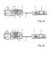
- Figures 3a and 3b describe the operation of the adjustment assembly according to the invention in the embodiment with a finned adjustment pulley 5 and a body with its upper part 6 having notches 9 'to realize the locking the adjustment set.
- the wheel 4 and the adjusting pulley 5 are integral and in their adjustment position can rotate to unroll or wind the cable 3 thus setting the length of the bracelet; moreover the wheel 4 and the adjusting pulley 5 are movable axially between a position where the wheel 4 is in the up position said position of rest and a position where the wheel 4 is in the low position called adjustment position.
- the wheel assembly 4 and adjustment pulley 5 is recalled by an elastic means, here a helical spring 7 extending between the lower surface of the wheel 4 and the lower part 6 'of the body 1, in its rest position.
- This set is partially housed in a body with upper 6 and lower 6 ' integral with the part 1 of the bracelet, a space being formed between the base of the lower part 6 'of the body and the lower part of the adjusting pulley 5 for allow the latter to move axially in the body.
- the wearer press the knob 4 which has the effect of pushing the adjusting pulley 5 in the body and to release the fins of the notches provided on the upper part 6 of the body.
- the pulley wheel assembly is then free to rotate and adjust the cable can be done.
- the adjustment pulley 5 can therefore be rotated to a position where its fins 9 will find themselves again in correspondence with the notches of the upper part 6 of the body: at this moment the wearer can release the pressure on the wheel 4, the elastic means 7 will recall the entire wheel-pulley in its rest position, that is to say with the wheel 4 in the high position and the fins 9 of the adjusting pulley 5 housed again in the notches of the upper part 6 of the body: the system of adjustment of the length of the bracelet will be blocked again.
- the wheel 4 can be made of a transparent material to allow the user easy alignment of the fins 9 of the adjusting pulley 5 with the corresponding notches in the upper part 6 of the body.
- This easy alignment can also be achieved with printed or embossed markers arranged on the wheel 4 and on the upper part 6 of the body.
- the adjustment device shown in the attached figures represents a first embodiment of the invention.
- the adjustment pulley comprises on one of its upper or lower faces concentric recesses for the receipt of a finger protruding from the first part of the band, this finger being introduced into one of the concentric recesses when the elastic means recalls the average means of actuation-adjusting pulley in its position of locking.
- the spring 7 may be replaced by a leaf spring disposed at the bottom of the housing of the part lower 6 'of the body for receiving the adjusting pulley 5, this spring recalling the adjusting pulley 5 upwards.
- notches were shown on the upper part 6 of the body but can be placed at other levels. It is even possible to plan a low rest position of the wheel 4 with a setting position with thumbwheel high by reversing the effect of the return means.
- the device of the The present invention makes it possible to obtain in a simple manner a precise and safe adjustment of the bandaged.
- this device can find an application in the case of a bracelet metal or it is better not to remove or add links.
- parts 1 and 2 of the band could form two particular links inserted into the chain of links, these two parts having for this purpose means of connection to the rest of the chain of links.
- the cable could for example cross several links to divide the spacing with the first part between several links.
- the bracelet is constituted by two son, preferably elastic, successively fitting the links, these two wires can be replaced by the cable associated with the set of adjustment according to the present invention.
- the setting could be distributed over the entire links by reducing the game between each of them which would not interfere aesthetics.
Landscapes
- Measuring Pulse, Heart Rate, Blood Pressure Or Blood Flow (AREA)
- Purses, Travelling Bags, Baskets, Or Suitcases (AREA)
- Surgical Instruments (AREA)
- Buckles (AREA)
Abstract
Description
- la figure 1 représente une vue de dessus en perspective des deux parties de la bande avec la molette de réglage sur l'une des parties.
- les figures 2a et 2b représentent une vue de dessus en perspective du système de réglage de la longueur de la bande selon une forme de réalisation de l'invention avec une poulie sous forme de corps à ailettes respectivement dans la position de réglage tendu et dans la position de réglage détendu,
- les figures 3a et 3b représentent une coupe des deux parties de la bande et leur dispositif de réglage de la longueur de la bande avec la poulie respectivement dans ses positions haute et basse.
Claims (9)
- Dispositif de réglage de la longueur d'une bande, cette bande comprenant deux parties (1 et 2) pouvant être rapprochées ou éloignées l'une de l'autre, caractérisé en ce qu'il comporte un ensemble de réglage (4, 5, 3) de la longueur de la bande, porté par la première partie (1) et comprenant au moins un câble (3), ce câble (3) reliant la première partie (1) avec la seconde (2), cet ensemble de réglage (4, 5, 3) comportant un moyen d'actionnement (4) du réglage par le porteur, une poulie de réglage (5) solidaire de ce moyen (4) à laquelle est fixée une des extrémités du câble (3) et autour de laquelle s'enroule une partie du câble (3), cette poulie étant associée à des moyens de verrouillage (6, 7, 9) capable de la bloquer en rotation dans une pluralité de positions de réglage.
- Dispositif de réglage selon la revendication 1, caractérisé en ce que le moyen d'actionnement comprend une molette (4) mobile axialement entre une position de verrouillage et une position de réglage, ladite molette étant mobile en rotation dans ladite position de réglage.
- Dispositif de réglage selon la revendication 1 ou 2, caractérisé en ce que la poulie de réglage (5) est logée à l'intérieur d'un corps creux (6, 6') solidaire de la première partie (1), en ce que ladite poulie comporte des ailettes (9) et en ce que ledit corps comporte des encoches (9') prévues pour coopérer avec lesdites ailettes pour bloquer en rotation ladite poulie en position de réglage.
- Dispositif de réglage selon la revendication 3, caractérisé en ce qu'il comprend en outre des moyens de rappel pour rappeler ladite molette dans la position de réglage.
- Dispositif de réglage selon la revendication 3 ou 4, caractérisé en ce que la corps (6, 6') est formé de deux parties fixées entre elles de manière inamovibie.
- Dispositif de réglage selon l'une quelconque des revendications précédentes, caractérisé en ce que l'autre extrémité du câble (3) est fixée sur la première partie (1) de la bande et en ce qu'une portion de la zone intermédiaire du câble est reçue dans la seconde partie (2) de manière à pouvoir coulisser dans celle-ci.
- Dispositif de réglage selon la revendication 6, caractérisé en ce que la seconde partie (2) de la bande comprend un moyen de guidage du câble (3), présentant un canal pour la réception du câble (3), la surface interne du canal présentant un faible coefficient de frottement.
- Dispositif de réglage selon la revendication 6, caractérisé en ce qu'au moins une poulie auxiliaire de renvoi est prévue sur la seconde partie (2) de la bande pour rediriger le câble (3) vers la première partie (1).
- Bracelet de montre, caractérisé en ce qu'il comprend un dispositif de réglage de longueur selon l'une quelconque des revendications précédentes.
Priority Applications (6)
| Application Number | Priority Date | Filing Date | Title |
|---|---|---|---|
| AT04009671T ATE354985T1 (de) | 2004-04-23 | 2004-04-23 | Längeneinstellungsvorrichtung eines bandes, insbesondere für ein uhrarmband |
| DE602004005006T DE602004005006T2 (de) | 2004-04-23 | 2004-04-23 | Längeneinstellungsvorrichtung eines Bandes, insbesondere für ein Uhrarmband |
| EP04009671A EP1588640B1 (fr) | 2004-04-23 | 2004-04-23 | Dispositif de réglage de la longueur d'une bande, notamment d'un bracelet de montre |
| US11/109,708 US20050237864A1 (en) | 2004-04-23 | 2005-04-20 | Device for adjusting the length of a band, in particular of a watch band |
| JP2005123320A JP2005305170A (ja) | 2004-04-23 | 2005-04-21 | バンド、特に時計バンドの長さを調節するデバイス |
| CN200510066347.7A CN1689475A (zh) | 2004-04-23 | 2005-04-22 | 调节带子特别是表带长度的装置 |
Applications Claiming Priority (1)
| Application Number | Priority Date | Filing Date | Title |
|---|---|---|---|
| EP04009671A EP1588640B1 (fr) | 2004-04-23 | 2004-04-23 | Dispositif de réglage de la longueur d'une bande, notamment d'un bracelet de montre |
Publications (2)
| Publication Number | Publication Date |
|---|---|
| EP1588640A1 true EP1588640A1 (fr) | 2005-10-26 |
| EP1588640B1 EP1588640B1 (fr) | 2007-02-28 |
Family
ID=34924708
Family Applications (1)
| Application Number | Title | Priority Date | Filing Date |
|---|---|---|---|
| EP04009671A Expired - Lifetime EP1588640B1 (fr) | 2004-04-23 | 2004-04-23 | Dispositif de réglage de la longueur d'une bande, notamment d'un bracelet de montre |
Country Status (6)
| Country | Link |
|---|---|
| US (1) | US20050237864A1 (fr) |
| EP (1) | EP1588640B1 (fr) |
| JP (1) | JP2005305170A (fr) |
| CN (1) | CN1689475A (fr) |
| AT (1) | ATE354985T1 (fr) |
| DE (1) | DE602004005006T2 (fr) |
Cited By (3)
| Publication number | Priority date | Publication date | Assignee | Title |
|---|---|---|---|---|
| EP2316298A1 (fr) * | 2009-10-29 | 2011-05-04 | The Swatch Group Research and Development Ltd. | Système de réglage de la longueur d'un bracelet |
| US11524188B2 (en) | 2018-10-09 | 2022-12-13 | Checkmate Lifting & Safety Ltd | Tensioning device |
| EP4555890A1 (fr) * | 2023-11-17 | 2025-05-21 | Manufacture d'Horlogerie Audemars Piguet SA | Dispositif de mise à l'aise pour montre-bracelet |
Families Citing this family (20)
| Publication number | Priority date | Publication date | Assignee | Title |
|---|---|---|---|---|
| US7600660B2 (en) * | 2004-03-11 | 2009-10-13 | Raymond Nevin Kasper | Harness tightening system |
| DE602006000823T2 (de) * | 2006-03-24 | 2009-04-16 | The Swatch Group Management Services Ag | Längenverstellbares Armband |
| EP2120627B1 (fr) * | 2006-12-01 | 2010-07-14 | LVMH Swiss Manufactures SA | Fermoir de bracelet avec dispositif de reglage de longueur |
| US20120221254A1 (en) * | 2009-11-06 | 2012-08-30 | Kateraas Espen D | Data collection unit with integrated closure system and sensor housing |
| US9285776B1 (en) * | 2013-03-15 | 2016-03-15 | Vortic, Llc | Band tightening system |
| FI126165B (en) * | 2013-06-11 | 2016-07-29 | Pulseon Oy | Strap for portable heart rate monitor and portable heart rate monitor |
| WO2014208074A1 (fr) * | 2013-06-24 | 2014-12-31 | パナソニックIpマネジメント株式会社 | Système d'interface d'entrée de potentiel bioélectrique, appareil de capteur d'entrée de potentiel bioélectrique, procédé d'entrée de potentiel bioélectrique, et programme associé |
| US10463141B2 (en) * | 2014-07-01 | 2019-11-05 | Heloisa Fitzgerald Jewelry | Wearable modular electronic device, such as to hold a selectable and/or replaceable biometric sensor in close proximity to and/or in physical contact with a wearer and/or to hold a battery |
| US9301580B1 (en) * | 2014-12-12 | 2016-04-05 | Alex And Ani, Llc | Sliding element for adjustable jewelry |
| CN105700678B (zh) * | 2015-12-30 | 2019-02-05 | 联想(北京)有限公司 | 一种电子设备及检测方法 |
| WO2017166237A1 (fr) * | 2016-03-31 | 2017-10-05 | 深圳市柔宇科技有限公司 | Appareil pouvant être porté |
| US10997956B2 (en) | 2016-09-18 | 2021-05-04 | Jonathan Amos Bodnar | Strap length adjusting apparatus |
| US20190323653A1 (en) * | 2018-04-24 | 2019-10-24 | Jordan B. Pollack | Portable and extendable support and mounting system utilizing a plurality of support mechanisms |
| CN109240066B (zh) * | 2018-11-23 | 2020-10-16 | 惠安县螺阳林飞燕汽车维修中心 | 一种具有感官自主调节隐匿式佩戴装置的手表 |
| CN109463858A (zh) * | 2018-11-23 | 2019-03-15 | 杨懿 | 一种通讯运动手环的紧锁结构 |
| CN109349750B (zh) * | 2018-11-30 | 2024-09-24 | 歌尔科技有限公司 | 一种腕戴装置 |
| CN112198780A (zh) * | 2020-10-21 | 2021-01-08 | 湖南中易顺电子科技有限公司 | 一种便于穿戴的卡环式gsm智能手表 |
| JP7746869B2 (ja) * | 2022-02-03 | 2025-10-01 | セイコーエプソン株式会社 | バンド、時計、およびバンド長さ調整機構 |
| CN115245227B (zh) * | 2022-06-23 | 2023-07-14 | 华为技术有限公司 | 连接装置、表带及可穿戴设备 |
| CN117338101B (zh) * | 2022-06-29 | 2026-01-16 | 广东小天才科技有限公司 | 表粒结构及智能手表 |
Citations (4)
| Publication number | Priority date | Publication date | Assignee | Title |
|---|---|---|---|---|
| GB191127973A (en) * | 1911-12-13 | 1912-11-21 | Richard Henry Jones | Improvements in Expanding or Adjustable Bracelets, Wristlets and Analogous Articles. |
| US5042177A (en) * | 1989-08-10 | 1991-08-27 | Weinmann Gmbh & Co. Kg | Rotary closure for a sports shoe, especially a ski shoe |
| EP0890323A2 (fr) * | 1997-07-11 | 1999-01-13 | Zanata S.p.A. | Crochet de lacage |
| US6322279B1 (en) * | 1997-11-04 | 2001-11-27 | Sports Carriers, Inc. | Adjustable attachment device |
Family Cites Families (9)
| Publication number | Priority date | Publication date | Assignee | Title |
|---|---|---|---|---|
| US1103776A (en) * | 1912-11-15 | 1914-07-14 | Ernest Jones | Bracelet and similar article. |
| US1817475A (en) * | 1929-07-08 | 1931-08-04 | Becker Emil | Closure for bracelets and the like |
| IT1193578B (it) * | 1981-01-28 | 1988-07-08 | Nordica Spa | Dispositivo di chiusura particolarmente per scarponi da sci |
| JPS6290516U (fr) * | 1985-11-26 | 1987-06-10 | ||
| WO1990014779A1 (fr) * | 1989-06-03 | 1990-12-13 | Puma Aktiengesellschaft Rudolf Dassler Sport | Chaussure a dispositif de fermeture et a tige en materiau deformable |
| JPH0746163Y2 (ja) * | 1990-11-28 | 1995-10-25 | ワイケイケイ株式会社 | ベルトの長さ調節具 |
| US6267390B1 (en) * | 1999-06-15 | 2001-07-31 | The Burton Corporation | Strap for a snowboard boot, binding or interface |
| JP3677255B2 (ja) * | 2002-03-29 | 2005-07-27 | 泰浩 中林 | スノーボード用ブーツ |
| US7076843B2 (en) * | 2003-10-21 | 2006-07-18 | Toshiki Sakabayashi | Shoestring tying apparatus |
-
2004
- 2004-04-23 AT AT04009671T patent/ATE354985T1/de not_active IP Right Cessation
- 2004-04-23 EP EP04009671A patent/EP1588640B1/fr not_active Expired - Lifetime
- 2004-04-23 DE DE602004005006T patent/DE602004005006T2/de not_active Expired - Fee Related
-
2005
- 2005-04-20 US US11/109,708 patent/US20050237864A1/en not_active Abandoned
- 2005-04-21 JP JP2005123320A patent/JP2005305170A/ja active Pending
- 2005-04-22 CN CN200510066347.7A patent/CN1689475A/zh active Pending
Patent Citations (4)
| Publication number | Priority date | Publication date | Assignee | Title |
|---|---|---|---|---|
| GB191127973A (en) * | 1911-12-13 | 1912-11-21 | Richard Henry Jones | Improvements in Expanding or Adjustable Bracelets, Wristlets and Analogous Articles. |
| US5042177A (en) * | 1989-08-10 | 1991-08-27 | Weinmann Gmbh & Co. Kg | Rotary closure for a sports shoe, especially a ski shoe |
| EP0890323A2 (fr) * | 1997-07-11 | 1999-01-13 | Zanata S.p.A. | Crochet de lacage |
| US6322279B1 (en) * | 1997-11-04 | 2001-11-27 | Sports Carriers, Inc. | Adjustable attachment device |
Cited By (5)
| Publication number | Priority date | Publication date | Assignee | Title |
|---|---|---|---|---|
| EP2316298A1 (fr) * | 2009-10-29 | 2011-05-04 | The Swatch Group Research and Development Ltd. | Système de réglage de la longueur d'un bracelet |
| US8893938B2 (en) | 2009-10-29 | 2014-11-25 | The Swatch Group Research And Development Ltd | System for adjusting the length of a bracelet or strap |
| US11524188B2 (en) | 2018-10-09 | 2022-12-13 | Checkmate Lifting & Safety Ltd | Tensioning device |
| EP4555890A1 (fr) * | 2023-11-17 | 2025-05-21 | Manufacture d'Horlogerie Audemars Piguet SA | Dispositif de mise à l'aise pour montre-bracelet |
| WO2025104653A1 (fr) | 2023-11-17 | 2025-05-22 | Manufacture D'horlogerie Audemars Piguet Sa | Dispositif de mise à l'aise pour montre-bracelet |
Also Published As
| Publication number | Publication date |
|---|---|
| US20050237864A1 (en) | 2005-10-27 |
| JP2005305170A (ja) | 2005-11-04 |
| DE602004005006D1 (de) | 2007-04-12 |
| EP1588640B1 (fr) | 2007-02-28 |
| ATE354985T1 (de) | 2006-03-15 |
| CN1689475A (zh) | 2005-11-02 |
| DE602004005006T2 (de) | 2007-12-13 |
Similar Documents
| Publication | Publication Date | Title |
|---|---|---|
| EP1588640B1 (fr) | Dispositif de réglage de la longueur d'une bande, notamment d'un bracelet de montre | |
| BE1016275A3 (fr) | Dipositif a volet enroulable autour d'un tambour. | |
| FR2532181A1 (fr) | Enrouleur de ceinture de securite pouvant prendre une position sans tension automatiquement memorisee | |
| EP0368798A1 (fr) | Tendeur de câble à enrouleur pour chaussure de ski | |
| EP2606762A1 (fr) | Fermoir à différents réglages de longueur de bracelet | |
| CH700818B1 (fr) | Appareil portable et montre. | |
| FR2560922A1 (fr) | Dispositif pour empecher l'application d'une tension excessive au moteur a ressort d'un store de fenetre | |
| CH702523B1 (fr) | Dispositif de réglage fin de la longueur utile d'un bracelet et fermoir correspondant. | |
| CH700230A2 (fr) | Fermoir de bracelet comportant un dispositif de réglage fin de la longueur utile du bracelet. | |
| FR2926489A1 (fr) | Outil de transfert de film de revetement | |
| EP0255788B1 (fr) | Enrouleur de sangle de ceinture de sécurité | |
| CH698981B1 (fr) | Dispositif de réglage de longueur pour bracelet, fermoire de bracelet et bracelet munis d'un tel dispositif. | |
| EP2111098B1 (fr) | Dispositif de deroulage d'un fil support souple pour plants grimpants | |
| CH697150A5 (fr) | Dispositif de réglage de la longueur d'une bande, notamment d'un bracelet de montre. | |
| EP3454136A1 (fr) | Boite de montre, montre-bracelet et kit d'assemblage d'une montre-bracelet la comprenant | |
| EP1916577A2 (fr) | Couronne à visser | |
| EP0010016B1 (fr) | Mécanisme de commande du déplacement d'une règle mobile parallèlement à elle-même sur une planche à dessin | |
| FR2466258A1 (fr) | Enrouleur de ceinture de securite a blocage d'enroulement selectif | |
| FR2544894A1 (fr) | Dispositif de commande mecanique a distance avec liaison flexible | |
| CH712319B1 (fr) | Dispositif de mise à la longueur d'un fermoir pour bracelet ou ceinture. | |
| CH707271A2 (fr) | Mouvement de montre comportant une fusée. | |
| CH702524B1 (fr) | Fermoir pour bracelet de pièce d’horlogerie permettant d’ajuster finement la longueur du bracelet. | |
| EP1716776A2 (fr) | Dispositif de réglage de la longueur d'un bracelet équipé d'un fermoir à lames articulées dépliables | |
| EP1659459B1 (fr) | Dispositif de protection pour l'accès au mécanisme de remontage d'une montre de poche | |
| EP4480340A1 (fr) | Dispositif de réglage de la longueur utile d'un bracelet et fermoir comprenant un tel dispositif |
Legal Events
| Date | Code | Title | Description |
|---|---|---|---|
| PUAI | Public reference made under article 153(3) epc to a published international application that has entered the european phase |
Free format text: ORIGINAL CODE: 0009012 |
|
| AK | Designated contracting states |
Kind code of ref document: A1 Designated state(s): AT BE BG CH CY CZ DE DK EE ES FI FR GB GR HU IE IT LI LU MC NL PL PT RO SE SI SK TR |
|
| AX | Request for extension of the european patent |
Extension state: AL HR LT LV MK |
|
| 17P | Request for examination filed |
Effective date: 20060426 |
|
| AKX | Designation fees paid |
Designated state(s): AT BE BG CH CY CZ DE DK EE ES FI FR GB GR HU IE IT LI LU MC NL PL PT RO SE SI SK TR |
|
| GRAP | Despatch of communication of intention to grant a patent |
Free format text: ORIGINAL CODE: EPIDOSNIGR1 |
|
| GRAS | Grant fee paid |
Free format text: ORIGINAL CODE: EPIDOSNIGR3 |
|
| GRAA | (expected) grant |
Free format text: ORIGINAL CODE: 0009210 |
|
| AK | Designated contracting states |
Kind code of ref document: B1 Designated state(s): AT BE BG CH CY CZ DE DK EE ES FI FR GB GR HU IE IT LI LU MC NL PL PT RO SE SI SK TR |
|
| PG25 | Lapsed in a contracting state [announced via postgrant information from national office to epo] |
Ref country code: IE Free format text: LAPSE BECAUSE OF FAILURE TO SUBMIT A TRANSLATION OF THE DESCRIPTION OR TO PAY THE FEE WITHIN THE PRESCRIBED TIME-LIMIT Effective date: 20070228 Ref country code: NL Free format text: LAPSE BECAUSE OF FAILURE TO SUBMIT A TRANSLATION OF THE DESCRIPTION OR TO PAY THE FEE WITHIN THE PRESCRIBED TIME-LIMIT Effective date: 20070228 Ref country code: SI Free format text: LAPSE BECAUSE OF FAILURE TO SUBMIT A TRANSLATION OF THE DESCRIPTION OR TO PAY THE FEE WITHIN THE PRESCRIBED TIME-LIMIT Effective date: 20070228 Ref country code: PL Free format text: LAPSE BECAUSE OF FAILURE TO SUBMIT A TRANSLATION OF THE DESCRIPTION OR TO PAY THE FEE WITHIN THE PRESCRIBED TIME-LIMIT Effective date: 20070228 Ref country code: FI Free format text: LAPSE BECAUSE OF FAILURE TO SUBMIT A TRANSLATION OF THE DESCRIPTION OR TO PAY THE FEE WITHIN THE PRESCRIBED TIME-LIMIT Effective date: 20070228 Ref country code: DK Free format text: LAPSE BECAUSE OF FAILURE TO SUBMIT A TRANSLATION OF THE DESCRIPTION OR TO PAY THE FEE WITHIN THE PRESCRIBED TIME-LIMIT Effective date: 20070228 |
|
| REG | Reference to a national code |
Ref country code: GB Ref legal event code: FG4D Free format text: NOT ENGLISH |
|
| REG | Reference to a national code |
Ref country code: CH Ref legal event code: EP |
|
| REF | Corresponds to: |
Ref document number: 602004005006 Country of ref document: DE Date of ref document: 20070412 Kind code of ref document: P |
|
| REG | Reference to a national code |
Ref country code: IE Ref legal event code: FG4D Free format text: LANGUAGE OF EP DOCUMENT: FRENCH |
|
| PG25 | Lapsed in a contracting state [announced via postgrant information from national office to epo] |
Ref country code: BG Free format text: LAPSE BECAUSE OF FAILURE TO SUBMIT A TRANSLATION OF THE DESCRIPTION OR TO PAY THE FEE WITHIN THE PRESCRIBED TIME-LIMIT Effective date: 20070529 |
|
| PG25 | Lapsed in a contracting state [announced via postgrant information from national office to epo] |
Ref country code: SE Free format text: LAPSE BECAUSE OF FAILURE TO SUBMIT A TRANSLATION OF THE DESCRIPTION OR TO PAY THE FEE WITHIN THE PRESCRIBED TIME-LIMIT Effective date: 20070531 |
|
| PG25 | Lapsed in a contracting state [announced via postgrant information from national office to epo] |
Ref country code: ES Free format text: LAPSE BECAUSE OF FAILURE TO SUBMIT A TRANSLATION OF THE DESCRIPTION OR TO PAY THE FEE WITHIN THE PRESCRIBED TIME-LIMIT Effective date: 20070608 |
|
| GBT | Gb: translation of ep patent filed (gb section 77(6)(a)/1977) |
Effective date: 20070522 |
|
| REG | Reference to a national code |
Ref country code: CH Ref legal event code: NV Representative=s name: ICB INGENIEURS CONSEILS EN BREVETS SA |
|
| PG25 | Lapsed in a contracting state [announced via postgrant information from national office to epo] |
Ref country code: PT Free format text: LAPSE BECAUSE OF FAILURE TO SUBMIT A TRANSLATION OF THE DESCRIPTION OR TO PAY THE FEE WITHIN THE PRESCRIBED TIME-LIMIT Effective date: 20070730 |
|
| NLV1 | Nl: lapsed or annulled due to failure to fulfill the requirements of art. 29p and 29m of the patents act | ||
| REG | Reference to a national code |
Ref country code: IE Ref legal event code: FD4D |
|
| PG25 | Lapsed in a contracting state [announced via postgrant information from national office to epo] |
Ref country code: SK Free format text: LAPSE BECAUSE OF FAILURE TO SUBMIT A TRANSLATION OF THE DESCRIPTION OR TO PAY THE FEE WITHIN THE PRESCRIBED TIME-LIMIT Effective date: 20070228 |
|
| BERE | Be: lapsed |
Owner name: THE SWATCH GROUP MANAGEMENT SERVICES AG Effective date: 20070430 |
|
| PG25 | Lapsed in a contracting state [announced via postgrant information from national office to epo] |
Ref country code: RO Free format text: LAPSE BECAUSE OF FAILURE TO SUBMIT A TRANSLATION OF THE DESCRIPTION OR TO PAY THE FEE WITHIN THE PRESCRIBED TIME-LIMIT Effective date: 20070228 Ref country code: CZ Free format text: LAPSE BECAUSE OF FAILURE TO SUBMIT A TRANSLATION OF THE DESCRIPTION OR TO PAY THE FEE WITHIN THE PRESCRIBED TIME-LIMIT Effective date: 20070228 |
|
| PLBE | No opposition filed within time limit |
Free format text: ORIGINAL CODE: 0009261 |
|
| STAA | Information on the status of an ep patent application or granted ep patent |
Free format text: STATUS: NO OPPOSITION FILED WITHIN TIME LIMIT |
|
| 26N | No opposition filed |
Effective date: 20071129 |
|
| PG25 | Lapsed in a contracting state [announced via postgrant information from national office to epo] |
Ref country code: BE Free format text: LAPSE BECAUSE OF NON-PAYMENT OF DUE FEES Effective date: 20070430 |
|
| PG25 | Lapsed in a contracting state [announced via postgrant information from national office to epo] |
Ref country code: GR Free format text: LAPSE BECAUSE OF FAILURE TO SUBMIT A TRANSLATION OF THE DESCRIPTION OR TO PAY THE FEE WITHIN THE PRESCRIBED TIME-LIMIT Effective date: 20070529 |
|
| PGFP | Annual fee paid to national office [announced via postgrant information from national office to epo] |
Ref country code: GB Payment date: 20080326 Year of fee payment: 5 |
|
| PG25 | Lapsed in a contracting state [announced via postgrant information from national office to epo] |
Ref country code: EE Free format text: LAPSE BECAUSE OF FAILURE TO SUBMIT A TRANSLATION OF THE DESCRIPTION OR TO PAY THE FEE WITHIN THE PRESCRIBED TIME-LIMIT Effective date: 20070228 |
|
| PG25 | Lapsed in a contracting state [announced via postgrant information from national office to epo] |
Ref country code: MC Free format text: LAPSE BECAUSE OF NON-PAYMENT OF DUE FEES Effective date: 20070430 |
|
| PGFP | Annual fee paid to national office [announced via postgrant information from national office to epo] |
Ref country code: CH Payment date: 20090325 Year of fee payment: 6 |
|
| PG25 | Lapsed in a contracting state [announced via postgrant information from national office to epo] |
Ref country code: CY Free format text: LAPSE BECAUSE OF FAILURE TO SUBMIT A TRANSLATION OF THE DESCRIPTION OR TO PAY THE FEE WITHIN THE PRESCRIBED TIME-LIMIT Effective date: 20070228 |
|
| PG25 | Lapsed in a contracting state [announced via postgrant information from national office to epo] |
Ref country code: LU Free format text: LAPSE BECAUSE OF NON-PAYMENT OF DUE FEES Effective date: 20070423 |
|
| PGFP | Annual fee paid to national office [announced via postgrant information from national office to epo] |
Ref country code: AT Payment date: 20090324 Year of fee payment: 6 Ref country code: DE Payment date: 20090504 Year of fee payment: 6 Ref country code: FR Payment date: 20090428 Year of fee payment: 6 Ref country code: IT Payment date: 20090331 Year of fee payment: 6 |
|
| PG25 | Lapsed in a contracting state [announced via postgrant information from national office to epo] |
Ref country code: TR Free format text: LAPSE BECAUSE OF FAILURE TO SUBMIT A TRANSLATION OF THE DESCRIPTION OR TO PAY THE FEE WITHIN THE PRESCRIBED TIME-LIMIT Effective date: 20070228 Ref country code: HU Free format text: LAPSE BECAUSE OF FAILURE TO SUBMIT A TRANSLATION OF THE DESCRIPTION OR TO PAY THE FEE WITHIN THE PRESCRIBED TIME-LIMIT Effective date: 20070901 |
|
| GBPC | Gb: european patent ceased through non-payment of renewal fee |
Effective date: 20090423 |
|
| PG25 | Lapsed in a contracting state [announced via postgrant information from national office to epo] |
Ref country code: GB Free format text: LAPSE BECAUSE OF NON-PAYMENT OF DUE FEES Effective date: 20090423 |
|
| REG | Reference to a national code |
Ref country code: CH Ref legal event code: PL |
|
| REG | Reference to a national code |
Ref country code: FR Ref legal event code: ST Effective date: 20101230 |
|
| PG25 | Lapsed in a contracting state [announced via postgrant information from national office to epo] |
Ref country code: AT Free format text: LAPSE BECAUSE OF NON-PAYMENT OF DUE FEES Effective date: 20100423 |
|
| PG25 | Lapsed in a contracting state [announced via postgrant information from national office to epo] |
Ref country code: CH Free format text: LAPSE BECAUSE OF NON-PAYMENT OF DUE FEES Effective date: 20100430 Ref country code: LI Free format text: LAPSE BECAUSE OF NON-PAYMENT OF DUE FEES Effective date: 20100430 Ref country code: DE Free format text: LAPSE BECAUSE OF NON-PAYMENT OF DUE FEES Effective date: 20101103 |
|
| PG25 | Lapsed in a contracting state [announced via postgrant information from national office to epo] |
Ref country code: IT Free format text: LAPSE BECAUSE OF NON-PAYMENT OF DUE FEES Effective date: 20100423 |
|
| PG25 | Lapsed in a contracting state [announced via postgrant information from national office to epo] |
Ref country code: FR Free format text: LAPSE BECAUSE OF NON-PAYMENT OF DUE FEES Effective date: 20100430 |