EP1588608B1 - Milchsammelstück - Google Patents
Milchsammelstück Download PDFInfo
- Publication number
- EP1588608B1 EP1588608B1 EP05003121A EP05003121A EP1588608B1 EP 1588608 B1 EP1588608 B1 EP 1588608B1 EP 05003121 A EP05003121 A EP 05003121A EP 05003121 A EP05003121 A EP 05003121A EP 1588608 B1 EP1588608 B1 EP 1588608B1
- Authority
- EP
- European Patent Office
- Prior art keywords
- claw
- milk
- tubular member
- along
- longitudinal axis
- Prior art date
- Legal status (The legal status is an assumption and is not a legal conclusion. Google has not performed a legal analysis and makes no representation as to the accuracy of the status listed.)
- Expired - Lifetime
Links
Images




Classifications
-
- A—HUMAN NECESSITIES
- A01—AGRICULTURE; FORESTRY; ANIMAL HUSBANDRY; HUNTING; TRAPPING; FISHING
- A01J—MANUFACTURE OF DAIRY PRODUCTS
- A01J5/00—Milking machines or devices
- A01J5/04—Milking machines or devices with pneumatic manipulation of teats
- A01J5/041—Milk claw
Definitions
- the invention relates to dairy equipment, and more particularly to milking claws.
- this invention relates to a milking claw with the features of the generic part of claim 1.
- a milking claw is part of a milking cluster which is an assembly attached to the dairy animal's udder during milking.
- the cluster includes the claw, four shell assemblies, four short milk tubes, four air tubes, and an air fork, for example as shown in EP 0 734 648 A1
- Each shell assembly includes an outer shell or teat cup, and an elastic inner liner called a teat cup liner or inflation.
- the short milk tube connects the teat cup shell assembly to the claw which in turn is connected to a milk transport hose subject to vacuum or negative pressure.
- the air tube connects the space between the teat cup liner and the shell to the air fork.
- the air fork is connected through one or more air lines to a pulsation device cycling vacuum off and on.
- the inside bore of the teat cup liner is at the system vacuum level, and the space between the teat cup liner and the shell is either at vacuum or at atmospheric pressure, depending on the cycle of the pulsation device.
- the vacuum on the inside of the liner causes the liner to collapse. This is known as the rest phase, during which there is no milk flow, i.e. the liner is closed.
- the rest phase during which there is no milk flow, i.e. the liner is closed.
- vacuum on the outside of the liner in the space between the liner and the shell such vacuum balances the vacuum on the inside of the liner, and the liner can relax or expand. This is the milk phase, during which milk flows, i.e. the liner is open.
- milking claw comprises a top provided with four inlets.
- Each inlet is generally tangential to the wall of the claw top and is downwardly inclined.
- the inlets intersect the frustoconical claw top generally in a rectangular arrangement which accommodates the natural arrangement of a cow's teats.
- the prior art milking claw top leads to the effect that milk entering the inlets will be started downwardly on a part hugging the wall of the frustoconical claw top, and the milk will start to swirl about the axis of the claw top.
- While a generally rectangular configuration of the milking claw is helpful for accommodating the natural arrangement of the cow's teats, care must be taken that the milk will not be blown back into an inlet other than the one from which the milk came.
- the milking claw forming the starting point of the invention ( US-A-5,080,041 ) shows the inlets of the claw top arranged in pairs on laterally opposite sides of the longitudinal axis. Here also care must be taken that the milk will not be blown back into an inlet other than the one from which the milk came.
- the object of the present invention is to improve above mentioned milking claw in this respect as far as the design of the claw top is concerned.
- Figs. 1-5 show prior art and are taken from EP 0 164 185 A2 incorporated herein by reference.
- Fig. 1 is a perspective view of a milking claw known in the prior art.
- Fig. 2 is an exploded perspective view of the milking claw of Fig. 1 .
- Fig. 3 is a top elevation view of the milking claw of Fig. 1 .
- Fig. 4 is a sectional view taken along line 4-4 of Fig. 3 .
- Fig. 5 is a top elevation view of the interior of the lower bowl of Fig. 2 .
- Figs. 6 and 7 show prior art and are taken from EP 0 734 648 A1 incorporated herein by reference.
- Fig. 6 is a side view of a milking cluster, including a milking claw, attached to a dairy animal.
- Fig. 7 is an enlarged view of a portion of Fig. 6 .
- Fig. 8 is a perspective view of a milking claw in accordance with the present invention.
- Fig. 9 is another perspective view of a milking claw in accordance with the invention.
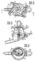
- Fig. 10 is an elevation view from above of the claw top of Figs. 8 and 9 .
- Fig. 11 is a perspective view from below of the interior surface of the claw top of Figs. 8-10 .
- Fig. 12 is an elevation view from below of the interior surface of the claw top of Fig. 11 .
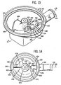
- Fig. 13 is a perspective view from above of the interior surface of a novel claw bottom in a further embodiment of a milking claw in accordance with the invention in combination with the present novel claw top.
- the novel claw bottom is the subject of commonly owned copending Patent Application filed on even date herewith attorney's file 05.0015.
- Fig. 14 is an elevation view from above of the interior surface of the claw bottom of Fig. 13 .
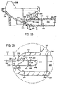
- Fig. 15 is a sectional view taken along line 15-15 of Fig. 13 .
- Fig. 16 is an enlarged view of a portion of Fig. 15 .
- Fig. 17 is a perspective view partially cut away of the claw bottom of Fig. 13 .
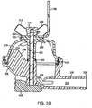
- Fig. 18 is a sectional view taken along line 18-18 of Fig. 9 .
- the milking claw 10 includes a bowl 12 and a cover 14 which has the general shape of a frustrum of a cone with the large diameter of the frustrum being connected to the bowl with the gasket 16 interposed between the bottom 18 of the cover and the internal seat 20 provided at the top of the bowl.
- the gasket 16 has an inturned lip which lies between the cover and the bowl and is compressed as the connector 22 is tightened.
- the connector has a threaded end 24 which extends through the central boss 25 of the cover and threads into a threaded sleeve 26 fixed in the central boss 28 in the bowl with gasket 27 captured between boss 25 and boss 28.
- the upper end of the connector 22 is provided with a washer 30 welded to the connector to overlie the loose washer 32 and gasket 34 so as to compress the gasket 34 against the top of the frusto-conical cover 14 when the connector is tightened.
- the upper end of the connector is shaped to provide a hanging eye 36.
- the upper portion of the frusto-conical cover 14 is provided with four inlet nipples 38, 40, 42, 44. Each nipple is generally tangential to the wall of the cover 14 and is downwardly inclined. With this arrangement, milk entering the nipples will be started downwardly on a path hugging the wall of the frusto-conical cover and cause the milk to swirl about the axis of the cover and bowl rather than dropping into the bowl and foaming. This swirling action in a downward and radially expanding path, coupled with the downward spiral of increasing cross-section in the bowl 12, virtually precludes the possibility of milk being blown back into a nipple other than the one from which the milk came.
- inlet 44 is above and in the same vertical plane as the center of the discharge fitting or outlet 46 leading radially out of the bowl.
- the outlet leads from the low point in the bowl.
- inlet nipples 38, 40 are closer to each other than they are to inlet nipples 42, 44.
- the inlets intersect the frusto-conical cover generally in a rectangular arrangement as can be seen in dotted lines in FIG. 3 .
- This generally rectangular configuration accommodates the natural arrangement of a cow's teats. They are not arranged in a square pattern, but they are, instead, in a rectangular pattern.
- the interior of the bowl 12 is molded to accommodate and provide an extension of the downward swirling action of the milk.
- a dam 48 which runs generally parallel to the outlet 46.
- the dam runs out to the outer wall of the bowl. Looking downwardly on the bowl, the area immediately to the right and in a clockwise direction from the area 50 is relatively shallow and the floor of the bowl sweeps downwardly in a spiral fashion as can be seen clearly in FIG. 2 .
- the downwardly spiraling configuration of the bowl provides an increasing cross-sectional area accommodating the increasing volume of milk likely to be in the flow path as the outlet 46 is approached.
- the dam 48 deflects the milk from the low point into the outlet 46.
- the outlet is so low relative to the rest of the floor or bottom of the bowl that pooling is virtually precluded.
- the milk keeps moving continuously from the inlet down through the spiraling path on the interior wall of the cover and into the bowl which guides the milk over a further spiraling path into the outlet.
- the milk is kept in motion and kinetic energy is preserved. Therefore, the amount of energy (vacuum) necessary to be applied to the system is kept at a minimum.
- the bowl is provided with a hanger bracket 56.
- the bowl is molded out of plastic. This makes it possible to obtain the downward spiraled flow path at reasonable cost.
- the cover is clear plastic to allow observation of the milk.
- Figs. 6 and 7 show a milking cluster 120 known in the prior art, and for which further reference may be had to U.S. Patents 4,530,307 , 5,178,095 , 5,218,924 and EP 0 164 185 A2 .
- Dairy animal 122 such as a cow, has an udder 124 and a plurality of teats 126, 128, 130, 132. The animal has a backbone 134 defining an axially extending longitudinal direction.
- a milking claw 136 has a plurality of inlets 138, 140, 142, 144, and an outlet 146.
- the claw lies along a central longitudinal axis 148 extending between the animal's front legs 131 and 133 and between the animal's rear legs 135 and 137 and generally parallel to backbone 134.
- Teat cups 150, 152, 154, 156 are each connected to a respective teat 126, 128, 130, 132 of udder 124.
- Short milk tubes 158, 160, 162, 164 each connect a respective claw inlet to a respective teat cup.
- An air fork 166 for which further reference may be had to the incorporated EP 0 734 648 A1 , has one or more inlets connected to respective one or more vacuum pulsation air lines 190, 192, and has four outlets connected to respective air tubes 180, 182, 184, 186 each connected to a respective teat cup 150, 152, 154, 156.
- a milk hose 188 is connected to claw outlet 146.
- the claw has an upper eye hook at 198 for hanging the claw when not in use.
- milk hose 188 and air lines 190, 192 extend forwardly and then laterally to the side, though the milk hose and the air lines may extend longitudinally rearwardly along axis 148 between the cow's rear legs 135 and 137, or longitudinally forwardly along axis 148 between the cow's front legs 131 and 133.
- the milking arrangement shown is of the alternating pulsation type. While vacuum is applied through air line 192, atmospheric air pressure is applied through air line 190, and vice versa. During the portion of the cycle when vacuum is applied through air line 192, such vacuum is applied through the fork to air tubes 180 and 182 to rear teat cups 150 and 152, such that rear teats 126 and 128 are in the milk phase, and milk flows from the rear teats through milk tubes 158 and 160 to claw inlets 138 and 140 for collection in claw 136 and discharge through outlet 146 and out through milk hose 188.
- atmospheric air pressure is applied by air line 190 through the fork to air tubes 184 and 186 to front teat cups 154 and 156 such that the front teats are in the rest phase.
- the atmospheric air pressure in the space between the teat cup shells and their respective teat cup liners or inflations causes a differential pressure across the liner due to the vacuum on the inside thereof, which in turn collapses the liner, blocking milk flow, and also squeezing and massaging the teat to force blood circulation, as above noted, and all as is known in the prior art. It is typical that air lines 190 and 192 will be alternated between their opposite vacuum and atmospheric air pressure states at a pulsation rate between 45 and 60 cycles per minute.
- Another type of pulsation system is the simultaneous or single shot type.
- the air fork has a singular inlet communicating with each of its four outlets connected respectively to air lines 180 , 182, 184, 186, such that all four teat cups 150, 152, 154, 156 will be in either the milk phase or in the rest phase at the same time, and all as is known in the prior art.
- Figs. 8-18 illustrate the present invention and show a milking claw 202 including a novel claw top 204.
- the claw bottom 206 may be a standard bowl as known in the prior art as shown in the above incorporated patents, or may be a novel bottom as later described herein in combination and which is the subject of commonly owned copending Patent Application, filed on even date herewith.
- the claw bottom may include a valve port 197, Fig. 8 , and a valve assembly 199, for blocking the vacuum present in outlet 216 from the inside of the claw if desired, allowing easier removal of the cluster from the animal, all as is known in the prior art.
- Milking claw 202 is provided for dairy animal 122 having the noted backbone 134 defining the noted axially extending longitudinal direction parallel to axis 148.
- Animal 122 such as a cow, has the noted four teats 126, 128, 130, 132 including a front pair of laterally spaced teats 130, 132 and a rear pair of laterally spaced teats 126, 128.
- Claw 202 has the noted claw bottom 206, and the noted claw top 204.
- Claw top 204 has four inlets 208, 210, 212, 214 connected to milk tubes 164, 162, 160, 158, respectively, and directing incoming milk flow into claw 202 respectively from teats 132, 130, 128, 126.
- Claw bottom 206 has an outlet 216 connected to milk hose 188 and subject to vacuum for drawing milk from the claw, as above described.
- Claw 202 lies along central longitudinal axis 148, Figs. 6 , 8-10 , which axis extends between the animal's legs and parallel to backbone 134.
- the inlets include a front pair of first and second inlets 208 and 210 laterally spaced on opposite sides of longitudinal axis 148 and receiving milk from front pair of teats 132 and 130 and directing such milk rearwardly into claw 202 on laterally opposite sides of longitudinal axis 148.
- the inlets include a rear pair of third and fourth inlets 212 and 214 laterally spaced on opposite sides of longitudinal axis 148 and receiving milk from the rear pair of teats 128 and 126 and directing such milk forwardly into claw 202 on laterally opposite sides of longitudinal axis 148.
- Claw top 204 has first, second, third and fourth interior contoured surfaces 218, 220, 222, 224, Figs. 12, 11 , directing milk therealong from the first, second, third and fourth inlets 208, 210, 212, 214, respectively.
- First and third inlets 208 and 212 and first and third contoured surfaces 218 and 222 are on a first lateral side (e.g. the left side) of longitudinal axis 148.
- Second and fourth inlets 210 and 214 and second and fourth contoured surfaces 220 and 224 are on a second lateral side (e.g. the right side) of longitudinal axis 148 opposite the noted first lateral side.
- Milk entering claw 202 through first inlet 208 flows rearwardly along first contoured surface 218 on the noted first lateral side of longitudinal axis 148.
- Milk entering the claw through second inlet 210 flows rearwardly along second contoured surface 220 on the noted second lateral side of longitudinal axis 148.
- Milk entering the claw through third inlet 212 flows forwardly along third contoured surface 222 on the noted first lateral side of longitudinal axis 148.
- Milk entering the claw through fourth inlet 214 flows forwardly along fourth contoured surface 224 on the noted second lateral side of longitudinal axis 148.
- First and third contoured surfaces 218 and 222 are longitudinally spaced from each other such that milk flowing rearwardly along first contoured surface 218 does not impinge milk flowing forwardly along third contoured surface 222.
- Second and fourth contoured surfaces 220 and 224 are longitudinally spaced from each other such that milk flowing rearwardly along second contoured surface 220 does not impinge milk flowing forwardly along fourth contoured surface 224.
- Claw top 204 has a first opening 226, Fig. 12 , from which first inlet 208 extends forwardly.
- Claw top 204 has a second opening 228, Figs. 11, 12 , from which second inlet 210 extends forwardly.
- Claw top 204 has a third opening 230 from which third inlet 212 extends rearwardly.
- Claw top 204 has a fourth opening 232 from which fourth inlet 214 extends rearwardly.
- First and third openings 226 and 230 are on the noted first lateral side of longitudinal axis 148.
- Second and fourth openings 228 and 232 are on the noted second lateral side of longitudinal axis 148.
- First opening 226 is rearward of third opening 230.
- Second opening 228 is rearward of fourth opening 232.
- First and third openings 226 and 230 are spaced laterally from second and fourth openings 228 and 232 such that flow along the noted first lateral side along the top does not intersect flow along the noted second
- Claw bottom 206 has longitudinally spaced front and rear ends 234 and 236, Figs. 8, 9 .
- First contoured surface 218 directs milk flow rearwardly and downwardly to rear end 236 of the claw bottom on the noted first lateral side of longitudinal axis 148.
- Second contoured surface 220 directs milk flow rearwardly and downwardly to rear end 236 of the claw bottom on the noted second lateral side of longitudinal axis 148.
- Third contoured surface 222 directs milk flow forwardly and downwardly to front end 234 of the claw bottom on the noted first lateral side of longitudinal axis 148.
- Fourth contoured surface 224 directs milk flow forwardly and downwardly to front end 234 of the claw bottom on the noted second lateral side of longitudinal axis 148.
- Claw top 204 has longitudinally spaced front and rear ends 238 and 240, Figs. 8-12 .
- First contoured surface 218 has a leading end 242 at opening 226 of first inlet 208 and has a trailing end 244 at rear end 240 of claw top 204.
- Second contoured surface 220 has a leading end 246 at opening 228 of second inlet 210 and has a trailing end 248 at rear end 240 of claw top 204.
- Third contoured surface 222 has a leading end 250 at opening 230 of third inlet 212 and has a trailing end 252 at front end 238 of claw top 204.
- Fourth contoured surface 224 has a leading end 254 at opening 232 of fourth inlet 214 and has a trailing end 256 at front end 238 of claw top 204.
- Leading end 242 of first contoured surface 218 is rearward of leading end 250 of third contoured surface 222.
- Leading end 246 of second contoured surface 220 is rearward of leading end 254 of fourth contoured surface 224.
- the noted first, second, third, fourth inlets 208, 210, 212, 214 have the noted first, second, third, fourth openings 226, 228, 230, 232, respectively, in claw top 204.
- First, second, third, fourth inlets 208, 210, 212, 214 include first, second, third, fourth tubular members 258, 260, 262, 264, respectively.
- Tubular member 258 has an entry end 266 and a discharge end 268 and a tubular extension 270 therebetween.
- Tubular member 260 has an entry end 272 and a discharge end 274 and a tubular extension 276 therebetween.
- Tubular member 262 has an entry end 278 and a discharge end 280 and a tubular extension 282 therebetween.
- Tubular member 264 has an entry end 284 and a discharge end 286 and a tubular extension 288 therebetween.
- Tubular extensions 270 and 282 of first and third tubular members 258 and 262 longitudinally cross each other on the noted first lateral side of longitudinal axis 148, such that entry end 266 of first tubular member 258 is forward of entry end 278 of third tubular member 262, and such that discharge end 268 of first tubular member 258 is rearward of discharge end 280 of third tubular member 262.
- Tubular extensions 276 and 288 of second and fourth members 260 and 264 longitudinally cross each other on the noted second lateral side of longitudinal axis 148, such that entry end 272 of second tubular member 260 is forward of entry end 284 of fourth tubular member 264, and such that discharge end 274 of second tubular member 260 is rearward of discharge end 286 of fourth tubular member 264.
- Milk from first teat 132 flows rearwardly through first tubular member 258 and is discharged rearwardly into claw 202 to flow rearwardly toward rear end 240 of claw top 204.
- Milk from second teat 130 flows rearwardly through second tubular member 260 and is discharged rearwardly into the claw to flow rearwardly toward rear end 240 of claw top 204.
- Milk from third teat 128 flows forwardly through third tubular member 262 and is discharged forwardly into the claw to flow forwardly toward front end 238 of claw top 204.
- Milk from fourth teat 126 flows forwardly through fourth tubular member 264 and is discharged forwardly into the claw to flow forwardly toward front end 238 of claw top 204.
- Discharge ends 268 and 280 of first and third tubular members 258 and 262 are on the noted first lateral side of longitudinal axis 148.
- Discharge ends 274 and 286 are on the noted second lateral side of longitudinal axis 148.
- Milk flow from first tubular member 258 does not intersect milk flow from third tubular member 262 along claw top 204 because milk flows rearwardly from discharge end 268 of first tubular member 258 from a point rearward of discharge end 280 of third tubular member 262.
- Milk flow from second tubular member 260 does not intersect milk flow from fourth tubular member 264 along claw top 204 because milk flows rearwardly from discharge end 274 of second tubular member 260 from a point rearward of discharge end 286 of fourth tubular member 264.
- Milk flow from third tubular member 262 does not intersect milk flow from first tubular member 258 along claw top 204 because milk flows forwardly from discharge end 280 of third tubular member 262 from a point forward of discharge end 268 of first tubular member 258.
- Milk flow from fourth tubular member 264 does not intersect milk flow from second tubular member 260 along claw top 204 because milk flows forwardly from discharge end 286 of fourth tubular member 264 from a point forward of discharge end 274 of second tubular member 260.
- novel claw top 204 may be used in conjunction with a standard lower bowl 206 as shown in the above noted incorporated patents.
- novel claw top 204 is used in conjunction with a novel claw bottom 306, Figs. 13-18 , which is the subject of commonly owned copending Patent Application filed on even date herewith.
- Claw bottom 306, Figs. 13-15 has an outlet 316 connected to milk hose 188 as above and subject to vacuum for drawing milk from the claw, as is known.
- Outlet 316 is a tubular member 318 extending from the claw bottom and having a flow passage 320, Fig. 15 , of a first vertical height 322, and having a nozzle 324 with an opening 326 passing milk therethrough from the claw bottom to flow passage 320.
- Nozzle opening 326 has a second vertical height 328, Fig. 16 , less than first vertical height 322.
- milk level in claw bottom 306 need only rise to the level 330 of the second lower vertical height 328 of nozzle 324 rather than to the level 332 of the first higher vertical height 322 of flow passage 320 of outlet tubular member 318 to provide a pressure differential between the vacuum in outlet 316 and the vacuum in the claw.
- the vacuum in the claw is less than the vacuum in outlet 316, i.e. the claw is at a higher relative pressure than outlet 316.
- the noted pressure differential is not established until the outlet is covered by milk in the claw bottom.
- the noted height differential enables the outlet to be covered sooner at lower level 330, rather than waiting for milk in the claw bottom to fill up to level 332.
- milk is drawn from the claw bottom in smaller more frequent slugs as compared to higher volume less frequent slugs while otherwise waiting for milk level to rise to level 332 of first vertical height 322.
- the shallow height 328 at level 330 creates a pressure differential at a lower fluid milk level than if nozzle 324 were not present.
- the pressure differential forces the milk out of the outlet 316 in smaller, more frequent slugs of milk. This more frequent taking away of the milk creates a more stable vacuum inside the claw, and reduces the amount of milk left in the claw at the end of milking.
- the bottom of the outlet is the lowest point 384 in the claw bottom, so milk is able to freely drain, which is an advantage over top-outlet claws.
- the outlet gravitationally drains the claw bottom, including in the absence of vacuum.
- Flow passage 320 of outlet tubular member 318 has a first cross-sectional flow area.
- Nozzle opening 326 has a second cross-sectional flow area which is greater than or equal to the noted first cross-sectional flow area, so as not to increase restriction nor create an additional point of restriction compared with outlet flow passage 320.
- the noted second cross-sectional flow area is defined by second vertical height 328 and by a peripheral distance 334 along the nozzle opening which is substantially greater than vertical height 328.
- Milk in flow passage 320 flows along a flow axis 336.
- Nozzle opening 326 is a generally horizontally extending slot 338, Figs. 15, 16 , having first, second and third sections 340, 342, 344, respectively, Fig.
- Second section 342 at the bight of the U is between first and third sections 340 and 344 which form the legs of the U.
- Second section 342 extends transversely of flow axis 336.
- First and third sections 340 and 344 extend longitudinally forwardly from second section 342 on laterally distally opposite sides of flow axis 336.
- First section 340 extends generally horizontally and parallel to flow axis 336 from a first open end 346, Fig. 16 , to a second closed end 348.
- Second section 342 extends horizontally and transversely to flow axis 336 from a first open end 350 to a second open end 352.
- Third section 344 extends generally horizontally and parallel to flow axis 336 from a first open end 354 to a second closed end 356.
- First open end 346 of first section 340 merges with first open end 350 of second section 342 at a rounded comer of the bight of the U and provides a continuous nozzle opening slot thereat.
- First open end 354 of third section 344 merges with second open end 352 of second section 342 at the other rounded comer of the bight of the U and provides a continuous nozzle opening slot thereat.
- Slot 338 is a continuous extension from second closed end 348 of first section 340 to second closed end 356 of third section 344, namely extending from second closed end 348 of first section 340 then along first section 340 to first open end 342 of first section 340 then to first open end 350 of second section 342 then along second section 342 to second open end 352 of second section 342 then to first open end 354 of third section 344 then along third section 344 to second closed end 356 of third section 344.
- the width of the noted second cross-sectional flow area is the noted continuous extension along U-shape 340, 342, 344 of slot 338.
- Claw bottom 306 has a sidewall 360, Figs. 15 , 17 .
- Tubular member 318 of outlet 316 extends from sidewall 360 exteriorly from the claw bottom.
- the outlet further includes an awning 362 extending from sidewall 360 interiorly of the claw bottom and defining the noted slot providing nozzle opening 326.
- Awning 362 extends into the claw bottom along flow axis 336 to an inner awning tip 364, Fig. 16 , spaced from sidewall 360.
- the awning has a pair of awning edges 366 and 368, Figs. 13, 14 , extending from sidewall 360 to inner awning tip 364.
- Awning edges 366 and 368 are on laterally distally opposite sides of flow axis 336.
- Slot 338 extends along inner awning tip 364 and along each of awning edges 366 and 368 in the noted U-shape.
- Claw bottom 306 has an interior lower surface 370, Figs. 17 , 16 .
- Awning edge 366 has a first bottom surface 372 spaced above lower interior surface 370 by a first gap 374.
- Inner awning tip 364 has a second bottom surface 376 spaced above lower interior surface 370 by a second gap 378.
- Awning edge 368 has a third bottom surface 380 spaced above lower interior surface 370 by a third gap 382.
- Each of first, second and third gaps 374, 378, 382 has a vertical height less than first vertical height 322, and preferably each equal to vertical height 328.
- First, second and third gaps 374, 378, 382 are horizontally continuous in the noted U-shape and define slot 338, i.e. the slot has a U-shape in a horizontal plane.
- Awning tip 364 is spaced from lower interior surface 370 by the noted gap 378 providing nozzle opening 326.
- the claw bottom further has a recessed surface 384, Figs. 15-17 , below interior lower surface 370 and extending through sidewall 360 exteriorly of claw bottom 306 and into flow passage 320 of outlet tubular member 318.
- the noted nozzle opening 326 has a vertical height preferably equal to the noted second vertical height 328.
- the noted first vertical height 322 extends between upper and lower reaches at 386 and 388.
- Second vertical height 328 extends between upper and lower reaches 390 and 392.
- Upper reach 390 of second vertical height 328 is below upper reach 386 of first vertical height 322.
- Lower reach 392 of second vertical height 328 is above lower reach 388 of first vertical height 322.
- Claw bottom 306 has distally opposite longitudinally spaced first and second front and rear ends 394 and 396, Fig. 13 , along longitudinal axis 148.
- the claw bottom has a dividing wall dam 398, Figs. 13-15 , extending longitudinally along longitudinal axis 148 from one of the noted ends, preferably rear end 396, part way towards the other of the ends.
- Outlet 316 is at the noted other end, preferably front end 394, opposite end 396 and longitudinally spaced from dam 398 by a longitudinal gap 400 therebetween.
- Tubular member 318 has an exterior section 402, Fig. 15 , extending exteriorly of claw bottom 306, and an interior section 404 extending interiorly of the claw bottom.
- Interior section 404 defines the noted slot 338 providing nozzle opening 326.
- Interior section 404 has internal concavely curved and radiused portions 406, 408 facing flow passage 320 and extending from the slot to facilitate gentle flow of milk and to facilitate easier cleaning.
- Claw top 204 and claw bottom 306 are mounted to each other, Fig. 18 , in conventional manner by a central shank bolt 410 which may be threaded and/or trapped at either or both of its top and bottom ends and retained by a nut 412 or the like retaining horizontal flange 414 of hook 198 against a compression gasket 416 compressively bearing against claw top 204.
- Claw bottom 306 may have a rubber bumper 418 attached thereto.
- Inner and outer annular sealing gaskets 420 and 422 are provided between claw top 204 and claw bottom 306.
- inlets 208 and 212 at their respective tubular extensions 258 and 262 pass by each other before entering the claw, and claw inlets 210 and 214 at their respective tubular extensions 260 and 264 pass by each other before entering the claw.
- the front inlet milk flow paths do not intersect the rear inlet milk flow paths, which in turn reduces agitation and degradation of the milk.
- Contours along the interior surface of the claw top, and preferably also in the mating claw bottom, direct the milk flow paths toward outlet flow passage 320. The milk follows the interior walls of the claw, rather than splashing on a lower surface or into a puddle after a free-fall from a height.
- the milk flow from the inlets clings to nearly tangential contours along the interior surface of the claw top and also preferably along the mating claw bottom and is guided toward the outlet flow passage 320.
- the milk flow paths from inlets 212 and 214 are directed toward outlet 316, and the milk flow paths from inlets 208 and 210 are directed toward the rear ends 240, 396 of the claw on opposite sides of dam wall 398 and change direction to flow back forwardly toward outlet 316, all with minimum intermingling and resultant agitation.
- the noted crossing of the inlets above the claw provides the noted desirable flow paths minimizing splashing within the claw which would otherwise agitate the milk and break down the fatty globules in the milk which otherwise causes degradation.
- the inlet orientations prevent back-jetting or cross-jetting of bacteria-laden milk in the form of aerosols to a diagonally opposite inlet because of the drastic change of direction required for same. For example, cross-jetting from inlet 208 at opening 226 to inlet 214 at opening 232, or vice versa, requires a turn of more than 90° to an opposite direction.
- cross-jetting from inlet 210 at opening 228 to inlet 212 at opening 230, or vice versa requires a turn and directional change of more than 90° to an opposite direction.
- the wider lateral spacing of inlets 208 and 210 at respective entry ends 266 and 272 is desirable to accommodate the wider spacing of a cow's front teats.
- the narrower lateral spacing of inlets 212 and 214 at respective entry ends 278 and 284 is desirable to accommodate the smaller lateral spacing of the cow's rear teats.
- the interior of the claw maintains separate milk flow paths from each of the respective four teats as the milk flow adheres to the interior surface of the claw top and claw bottom until the milk flow reaches the bottom of the claw bottom at a reduced flow rate and with reduced agitation, whereat the milk flow paths commingle and merge and exit through flow passage 320.
- milk hose 188, Figs. 6, 7 is routed toward the front of the dairy animal, and outlets 46, 146, 216, 316 point toward the front of the dairy animal.
- claw bottom 206, 306 may be rotated 180° about a vertical axis such that the milk hose is routed toward the rear of the dairy animal, and outlets 216, 316 point toward the rear of the dairy animal, or further alternatively, claw bottom 206, 306 may be rotated 90° about a vertical axis such that the milk hose is routed toward the side of the dairy animal, and outlets 216, 316 point toward the side of the dairy animal.
- the claw top preferably remains in the orientation shown, with inlets 208, 210 pointing toward the front of the dairy animal for connection to the front pair of laterally spaced teats, and with inlets 212, 214 pointing toward the rear of the dairy animal for connection to the rear pair of laterally spaced teats.
- first opening 226, Fig. 12 in claw top 204 introduces milk flow into the claw along a first rearwardly directed milk flow path at 218 traversing rearwardly of third opening 230. It is preferred that opening 226 be rearward of or at least laterally adjacent to opening 230, but not forward of opening 230. Second opening 228 introduces milk flow into the claw along a second rearwardly directed milk flow path at 220 traversing rearwardly of fourth opening 232. It is preferred that opening 228 be rearward of or at least laterally adjacent to opening 230, but not forward of opening 232. Third opening 230 introduces milk flow into the claw along a third forwardly directed milk flow path at 222 traversing forwardly of first opening 226.
- opening 230 be forward of opening 226 or at least laterally adjacent thereto, but not rearward of opening 226.
- Fourth opening 232 introduces milk flow into the claw along a fourth forwardly directed milk flow path at 224 traversing forwardly of opening 228. It is preferred that opening 232 be forward of opening 228 or at least laterally adjacent thereto, but not rearward of opening 228.
- the noted first and third milk flow paths at 218 and 222 are nonintersecting such that milk flowing from first opening 226 along the milk flow path at 218 does not intersect milk flowing from the third opening 230 along the third milk flow path at 222.
- first opening 226 is rearward of third opening 230
- second opening 228 is rearward of fourth opening 232
- First and third openings 226 and 230 have respective leading portions 432 and 434 laterally adjacent each other.
- Second and fourth openings 228 and 232 have respective leading portions 436 and 438 laterally adjacent each other.
- First and third openings 226 and 230 have respective trailing portions 440 and 442 longitudinally spaced from each other.
- Second and fourth openings 228 and 232 have respective trailing portions 446 and 448 longitudinally spaced from each other.
- first, second, third, fourth contoured surfaces 218, 220, 222, 232, Fig. 12 terminate substantially tangentially to respective mating surfaces 450, 452, 454, 456, Fig. 14 , of claw bottom 306 such that milk is delivered to the claw bottom with minimal splashing.
- First, second, third, fourth contoured surfaces, 218, 220, 222, 232 are initially substantially tangential to the noted first, second, third, fourth milk flow paths from respective openings 226, 228, 230, 232 of respective inlets 208, 210, 212, 214, and then contour and curve downwardly to mate with and direct milk flow substantially tangentially to the noted respective mating surfaces 450, 452, 454, 456 of the claw bottom.
- the upper interior surface of claw top 204 includes a rearward separational surface 458 in the form of a flat planar surface extending longitudinally along axis 148 and laterally between channeled or grooved contoured surfaces 218 and 220, or in the form of a longitudinally extending hump or dome along axis 148 and extending out of the page as viewed in Fig. 12 .
- Separational surface 458 is laterally between first and second contoured surfaces 218 and 220 and provides a rearward separational director therebetween which directs milk flow from first inlet 208 along first contoured surface 218 and away from second contoured surface 220, and which directs milk flow from second inlet 210 along second contoured surface 220 and away from first contoured surface 218.
- the upper interior surface of claw top 204 further includes a forward separational surface 460 in the form of a flat planar surface extending longitudinally along axis 148 and laterally between channeled or grooved contoured surfaces 222 and 224, or in the form of a hump or dome extending longitudinally along axis 148 and out of the page as viewed in Fig. 12 .
- Separational surface 460 is laterally between third and fourth contoured surfaces 222 and 224 and provides a forward separational director therebetween which directs milk flow from third inlet 212 at opening 230 along third contoured surface 222 and away from fourth contoured surface 224, and which directs milk flow from fourth inlet 214 at opening 232 along fourth contoured surface 224 and away from third contoured surface 222.
- first and third tubular members 258 and 262, Figs. 9 , 10 cross each other at a first crossing zone, and in a preferred construction these members are structurally connected at such crossing zone by member 462.
- Second and fourth tubular members 260 and 264 cross each other at a second crossing zone, and in a preferred construction these members are structurally connected at such crossing zone by member 464.
- a first brace 466 further structurally connects and bridges between first and third tubular members 258 and 262 at the first crossing zone.
- a second brace 468 further structurally connects and bridges between second and fourth tubular members 260 and 264 at the second crossing zone.
- Claw bottom 306 has lower interior surfaces 472, 474, Fig. 14 , sloped from areas 476, 478 adjacent dividing wall dam 398 towards the outlet to promote drainage to the outlet.
- Interior surfaces 472, 474 are shaped to form a path for milk to flow from areas 476, 478 adjacent dividing wall dam 398 towards outlet 316.
- Inlets 208, 210 supply milk to rearward end 396 of claw bottom 306.
- Inlets 212, 214 supply milk to forward end 394 of claw bottom 306.
- Interior surfaces 472, 474 are preferably shaped to form paths for milk to travel from areas 476, 478 adjacent dividing wall dam 398 towards outlet 316 without intersecting flow from inlets 212, 214 directed toward forward end 394 until the milk is adjacent outlet 316 at nozzle opening 326.
- Claw bottom 306 has the noted interior contoured surfaces 450, 452, 454, 456 tangentially receiving milk flow from respective contoured surfaces 218, 220, 222, 224 of claw top 204.
- the lower interior surfaces are sloped from distal areas towards the outlet to promote drainage to the outlet.
Landscapes
- Life Sciences & Earth Sciences (AREA)
- Animal Husbandry (AREA)
- Environmental Sciences (AREA)
- External Artificial Organs (AREA)
- Housing For Livestock And Birds (AREA)
- Dairy Products (AREA)
Claims (10)
- Milchsammelstück (202) für Milchvieh (122),
wobei das Milchvieh (122) ein Rückgrat (134), das eine sich axial erstreckende Längsrichtung definiert, und einen Euter mit vier Zitzen (126, 128, 130, 132), die ein vorderes Paar lateral beabstandeter Zitzen (130, 132) und ein hinteres Paar lateral beabstandeter Zitzen (126, 128) umfassen, aufweist,
wobei das Sammelstück (202) einen Oberteil (204) mit vier Einlässen (208, 210, 212, 214) aufweist, die jeweils von den vier Zitzen (126, 128, 130, 132) ankommenden Milchfluss in das Sammelstück (202) leiten,
wobei das Sammelstück (202) einen Unterteil (206) mit einem Auslass (216) aufweist, der einem Vakuum zum Absaugen von Milch daraus ausgesetzt ist,
wobei das Sammelstück (202) eine mittlere Längsachse (148) aufweist,
wobei die Einlässe (208, 210, 212, 214) des Sammelstückoberteils (204) ein vorderes Paar aus einem ersten (208) und einem zweiten (210) Einlass, die auf einander gegenüberliegenden Seiten der Längsachse (148) zur Aufnahme von Milch von dem vorderen Paar Zitzen (132, 130) und Leiten solcher Milch nach hinten in das Sammelstück (202) auf lateral gegenüberliegenden Seiten der Längsachse (148) lateral beabstandet sind, und ein hinteres Paar aus einem dritten (212) und einem vierten (214) Einlass, die auf einander gegenüberliegenden Seiten der Längsachse (148) zur Aufnahme von Milch von dem hinteren Paar Zitzen (128, 126) und Leiten solcher Milch nach vorne in das Sammelstück (202) auf lateral gegenüberliegenden Seiten der Längsachse (148) lateral beabstandet sind, umfassen,
wobei der Sammelstückoberteil (204) eine erste Öffnung (226) aufweist, von der sich der erste Einlass (208) nach vorne erstreckt,
wobei der Sammelstückoberteil (204) eine zweite Öffnung (228) aufweist, von der sich der zweite Einlass (210) nach vorne erstreckt,
wobei der Sammelstückoberteil (204) eine dritte Öffnung (230) aufweist, von der sich der dritte Einlass (212) nach hinten erstreckt,
wobei der Sammelstückoberteil (204) eine vierte Öffnung (232) aufweist, von der sich der vierte Einlass (214) nach hinten erstreckt,
wobei sich die erste (226) und die dritte (230) Öffnung auf einer ersten lateralen Seite der Längsachse (148) befinden und
sich die zweite (228) und die vierte (232) Öffnung auf einer zweiten lateralen Seite der Längsachse (148) befinden,
dadurch gekennzeichnet, dass
die erste Öffnung (226) Milchfluss entlang einem ersten, nach hinten gerichteten Milchflussweg, der rückwärtig der dritten Öffnung (230) verläuft, in das Sammelstück (202) einleitet,
die zweite Öffnung (228) Milchfluss entlang einem zweiten, nach hinten gerichteten Milchflussweg, der rückwärtig der vierten Öffnung (232) verläuft, in das Sammelstück (202) einleitet,
die dritte Öffnung (230) Milchfluss entlang einem dritten, nach vorne gerichteten Milchflussweg, der vor der ersten Öffnung (226) verläuft, in das Sammelstück (202) einleitet,
die vierte Öffnung (232) Milchfluss entlang einem vierten, nach vorne gerichteten Milchflussweg, der vor der zweiten Öffnung (228) verläuft, in das Sammelstück (202) einleitet,
sich der erste und der dritte Milchflussweg nicht schneiden, so dass von der ersten Öffnung (226) entlang dem Milchflussweg fließende Milch von der dritten Öffnung (230) entlang dem dritten Milchflussweg fließende Milch nicht schneidet, und
sich der zweite und der vierte Milchflussweg nicht schneiden, so dass von der zweiten Öffnung (228) entlang dem Milchflussweg fließende Milch von der vierten Öffnung (232) entlang dem vierten Milchflussweg fließende Milch nicht schneidet. - Milchsammelstück (202) nach Anspruch 1, dadurch gekennzeichnet, dass
sich die erste Öffnung (226) hinter der dritten Öffnung (230) befindet und
sich die zweite Öffnung (228) hinter der vierten Öffnung (232) befindet und/oder
die erste (226) und die dritte (230) Öffnung Vorderteile aufweisen, die lateral nebeneinander beabstandet sind, und die zweite (228) und die vierte (232) Öffnung Vorderteile aufweisen, die lateral nebeneinander beabstandet sind, und/oder
die erste (226) und die dritte (230) Öffnung Hinterteile aufweisen, die in Längsrichtung voneinander beabstandet sind, und die zweite (228) und die vierte (232) Öffnung Hinterteile aufweisen, die in Längsrichtung voneinander beabstandet sind, und/oder
die erste (226) und die dritte (230) Öffnung lateral von der zweiten (228) und der vierten (232) Öffnung beabstandet sind, so dass Fluss entlang der ersten lateralen Seite entlang dem Oberteil (204) Fluss entlang der zweiten lateralen Seite entlang dem Oberteil nicht schneidet. - Milchsammelstück nach Anspruch 1 oder 2, dadurch gekennzeichnet, dass
das Klauenoberteil erste (218), zweite (220), dritte (222) und vierte (224) innere profilierte Flächen aufweist, die Milch daran entlang vom ersten (208), zweiten (210), dritten (212) bzw. vierten (214) Einlass leiten,
sich der erste (208) und der dritte (212) Einlass und die erste (218) und die dritte (222) profilierte Fläche auf einer ersten lateralen Seite der Längsachse (148) befinden,
sich der zweite (210) und der vierte (214) Einlass und die zweite (220) und die vierte (224) profilierte Fläche auf einer zweiten lateralen Seite der Längsachse (148) gegenüber der ersten lateralen Seite befinden,
durch den ersten Einlass (208) in das Sammelstück (202) eintretende Milch entlang der ersten profilierten Fläche (218) auf der ersten lateralen Seite der Längsachse (148) nach hinten fließt,
durch den zweiten Einlass (210) in das Sammelstück (202) eintretende Milch entlang der zweiten profilierten Fläche (220) auf der zweiten lateralen Seite der Längsachse (148) nach hinten fließt,
durch den dritten Einlass (212) in das Sammelstück (202) eintretende Milch entlang der dritten profilierten Fläche (222) auf der ersten lateralen Seite der Längsachse (148) nach vorne fließt,
durch den vierten Einlass (214) in das Sammelstück (202) eintretende Milch entlang der vierten profilierten Fläche (224) auf der zweiten lateralen Seite der Längsachse (148) nach vorne fließt,
die erste (218) und die dritte (222) konturierte Fläche in Längsrichtung voneinander beabstandet sind, so dass entlang der ersten profilierten Fläche (218) nach hinten fließende Milch nicht auf entlang der dritten profilierten Fläche (222) nach vorne fließende Milch auftrifft,
die zweite (220) und die vierte (224) profilierte Fläche in Längsrichtung voneinander beabstandet sind, so dass entlang der zweiten profilierten Fläche (220) nach hinten fließende Milch nicht auf entlang der vierten profilierten Fläche (224) nach vorne fließende Milch auftritt. - Milchsammelstück (202) nach Anspruch 3, dadurch gekennzeichnet, dass
der Sammelstückunterteil (206) ein Vorderende (234) und ein Hinterende (236) aufweist, die in Längsrichtung voneinander beabstandet sind,
die erste profilierte Fläche (218) Milchfluss nach hinten und nach unten zum Hinterende (236) des Sammelstückunterteils (206) auf der ersten lateralen Seite der Längsachse (148) leitet,
die zweite profilierte Fläche (220) Milchfluss nach hinten und nach unten zum Hinterende (236) des Sammelstückunterteils (206) auf der zweiten lateralen Seite der Längsachse (148) leitet,
die dritte profilierte Fläche (222) Milchfluss nach vorne und nach unten zum Vorderende (234) des Sammelstückunterteils (206) auf der ersten lateralen Seite der Längsachse leitet,
die vierte profilierte Fläche (224) Milchfluss nach vorne und nach unten zum Vorderende (234) des Sammelstückunterteils (206) auf der zweiten lateralen Seite der Längsachse (148) leitet. - Milchsammelstück (202) nach Anspruch 3 oder 4,
dadurch gekennzeichnet, dass
die erste (218), die zweite (220), die dritte (222) und die vierte (224) profilierte Fläche im Wesentlichen tangential zu jeweiligen GegenFlächen des Sammelstückunterteils (206) enden, so dass Milch dem Sammelstückunterteil (206) unter minimalem Verspritzen zugeführt wird, und/oder
wobei die erste (218), die zweite (220), die dritte (222) und die vierte (224) profilierte Fläche vom ersten (208), zweiten (210), dritten (212) bzw, vierten (214) Einlass anfangs im Wesentlichen tangential zum ersten, zweiten, dritte bzw. vierten Milchflussweg verlaufen. - Milchsammelstück (202) nach Anspruch 3, 4 oder 5,
dadurch gekennzeichnet, dass
der Sammelstückoberteil (204) ein Vorderende (238) und ein Hinterende (240) aufweist, die in Längsrichtung voneinander beabstandet sind,
die erste profilierte Fläche (218) ein Vorderende (242) am ersten Einlass (208) und ein Hinterende (244) am Hinterende (240) des Sammelstückoberteils (204) aufweist,
die zweite profilierte Fläche (220) ein Vorderende (246) am zweiten Einlass (210) und ein Hinterende (248) am Hinterende (240) des Sammelstückoberteils (204) aufweist,
die dritte profilierte Fläche (222) ein Vorderende (250) am dritten Einlass (212) und ein Hinterende (252) am Vorderende (238) des Sammelstückoberteils (204) aufweist,
die vierte profilierte Fläche (224) ein Vorderende (254) am vierten Einlass (214) und ein Hinterende (256) am Vorderende (238) des Sammelstückoberteils (204) aufweist,
sich das Vorderende (242) der ersten profilierten Fläche (218) hinter dem Vorderende (250) der dritten profilierten Fläche (222) befindet,
sich das Vorderende (246) der zweiten profilierten Fläche (220) hinter dem Vorderende (254) der vierten profilierten Fläche (224) befindet. - Milchsammelstück (202) nach Anspruch 3, 4 oder 5, dadurch gekennzeichnet, dass es weiterhin Folgendes umfasst:eine hintere Trennfläche lateral zwischen der ersten (218) und der zweiten (220) profilierten Fläche, die eine hintere Trennleitvoxxichtung zwischen ihnen bildet,wobei die hintere Trennleitvorrichtung Milchfluss von dem ersten Einlass (208) entlang der ersten profilierten Fläche (218) und von der zweiten profilierten Fläche (220) weg leitet, wobei die hintere Trennleitvorrichtung Milchfluss von dem zweiten Einlass (210) entlang der zweiten profilierten Fläche (220) und von der ersten profilierten Fläche (218) weg leitet,eine vordere Trennfläche lateral zwischen der dritten (222) und der vierten (224) profilierten Fläche, die eine vordere Trennleitvorrichtung zwischen ihnen bildet, wobei die vordere Trennleitvorrichtung Milchfluss von dem dritten Einlass (212) entlang der dritten profilierten Fläche (222) und von der vierten profilierten Fläche (224) weg leitet,wobei die vordere Trennleitvorrichtung Milchfluss von dem vierten Einlass (214) entlang der vierten profilierten Fläche (224) und von der dritten profilierten Fläche (222) weg leitet.
- Milchsammelstück (202) nach einem der vorhergehenden Ansprüche, dadurch gekennzeichnet, dass
der erste (208), der zweite (210), der dritte (212) und der vierte (214) Einlass ein erstes (258), ein zweites (260), ein drittes (262) bzw. ein viertes (264) röhrenförmiges Glied umfassen,
wobei jedes röhrenförmige Glied (258, 260, 262, 264) ein Eintrittsende (266, 272, 278, 284) und ein Austragsende (268, 274, 280, 286) und eine röhrenförmige Verlängerung (270, 276, 282, 288) dazwischen aufweist,
die röhrenförmigen Verlängerungen (270, 282) des ersten (258) und des dritten (262) röhrenförmigen Glieds sich auf einer ersten lateralen Seite der Längsachse (148) in Längsrichtung überkreuzen, und die röhrenförmigen Verlängerungen (276, 288) des zweiten (260) und des vierten (264) röhrenförmigen Glieds sich in Längsrichtung auf einer zweiten lateralen Seite der Längsachse (148) überkreuzen,
wobei die zweite lateral Seite der ersten lateralen Seite gegenüberliegt. - Milchsammelstück (202) nach Anspruch 8, dadurch gekennzeichnet, dass
das Eintrittsende (266) des ersten röhrenförmigen Glieds (258) vor dem Eintrittsende (278) des dritten röhrenförmigen Glieds (262) liegt und das Austragsende (268) des ersten röhrenförmigen Glieds (258) hinter dem Austragsende (280) des dritten röhrenförmigen Glieds (262) liegt, während das Eintrittsende (272) des zweiten röhrenförmigen Glieds (260) vor dem Eintrittsende (284) des vierten röhrenförmigen Glieds (264) liegt und das Austragsende (274) des zweiten röhrenförmigen Glieds (260) hinter dem Austragsende (286) des vierten röhrenförmigen Glieds (264) liegt, und/oder
sich das erste (258) und das dritte (262) röhrenförmige Glied in einer ersten Überkreuzungszone überkreuzen, während sich das zweite (260) und das vierte (264) röhrenförmige Glied in einer zweiten Kreuzungszone überkreuzen und weiterhin ein erstes strukturelles Verbindungsglied (462) zwischen dem ersten (258) und dem dritten (262) röhrenförmigen Glied in der ersten Überkreuzungszone und ein zweites strukturelles Verbindungsglied (464) zwischen dem zweiten (260) und dem vierten (264) röhrenförmigen Glied in der zweiten Überkreuzungszone vorgesehen sind. - Milchsammelstück (202) nach Anspruch 8 oder 9, dadurch gekennzeichnet, dass
der Sammelstückoberteil (204) ein Vorderende (238) und ein Hinterende (240) aufweist, die in Längsrichtung voneinander beabstandet sind,
Milch von der ersten Zitze (126) durch das erste röhrenförmige Glied (258) nach hinten fließt und nach hinten in das Sammelstück (202) ausgetragen wird, um nach hinten zum Hinterende (240) des Sammelstückoberteils (204) zu fließen,
Milch von der zweiten Zitze (128) durch das zweite röhrenförmige Glied (260) nach hinten fließt und nach hinten in das Sammelstück (202) ausgetragen wird, um nach hinten zum Hinterende (240) des Sammelstückoberteils (204) zu fließen,
Milch von der dritten Zitze (130) durch das dritte röhrenförmige Glied (262) nach vorne fließt und nach vorne in das Sammelstück (202) ausgetragen wird, um nach vorne zum Vorderende (238) des Sammelstückoberteils (204) zu fließen,
Milch von der vierten Zitze (132) durch das vierte röhrenförmige Glied (264) nach vorne fließt und nach vorne in das Sammelstück (202) ausgetragen wird, um nach vorne zum Vorderende (238) des Sammelstückoberteils (204) zu fließen,
sich die Austragsenden (268, 280) des ersten (258) und des dritten (262) röhrenförmigen Glieds auf einer ersten lateralen Seite der Längsachse (148) befinden,
sich die Autragsenden (274, 286) des zweiten (260) und des vierten (264) röhrenförmigen Glieds auf einer zweiten lateralen Seite der Längsachse befinden, wobei die zweite laterale Seite der ersten lateralen Seite gegenüberliegt,
Milchfluss vom ersten röhrenförmigen Glied (258) Milchfluss vom dritten röhrenförmigen Glied (262) entlang dem Sammelstückoberteil (204) nicht schneidet, weil Milch vom Austragsende (268) des ersten röhrenförmigen Glieds (258) von einer Stelle hinter dem Austragsende (280) des dritten röhrenförmigen Glieds (262) nach hinten fließt,
Milchfluss vom zweiten röhrenförmigen Glied (260) Milchfluss vom vierten röhrenförmigen Glied (264) entlang dem Sammelstückoberteil (204) nicht schneidet, weil Milch vom Austragsende (274) des zweiten röhrenförmigen Glieds (260) von einer Stelle hinter dem Austragsende (286) des vierten röhrenförmigen Glieds (264) nach hinten fließt,
Milchfluss vom dritten röhrenförmigen Glied (262) Milchfluss vom ersten röhrenförmigen Glied (258) entlang dem Sammelstückoberteil (204) nicht schneidet, weil Milch vom Austragsende (280) des dritten röhrenförmigen Glieds (262) von einer Stelle vor dem Austragsende (268) des ersten röhrenförmigen Glieds (258) nach vorne fließt,
Milchfluss vom vierten röhrenförmigen Glied (264) Milchfluss vom zweiten röhrenförmigen Glied (260) entlang dem Sammelstückoberteil (204) nicht schneidet, weil Milch vom Austragsende (286) des vierten röhrenförmigen Glieds (264) von einer Stelle vor dem Austragsende (274) des zweiten röhrenförmigen Glieds nach vorne fließt.
Applications Claiming Priority (2)
| Application Number | Priority Date | Filing Date | Title |
|---|---|---|---|
| US10/828,425 US7021239B2 (en) | 2004-04-20 | 2004-04-20 | Milking claw top |
| US828425 | 2004-04-20 |
Publications (2)
| Publication Number | Publication Date |
|---|---|
| EP1588608A1 EP1588608A1 (de) | 2005-10-26 |
| EP1588608B1 true EP1588608B1 (de) | 2008-08-20 |
Family
ID=34933751
Family Applications (1)
| Application Number | Title | Priority Date | Filing Date |
|---|---|---|---|
| EP05003121A Expired - Lifetime EP1588608B1 (de) | 2004-04-20 | 2005-02-15 | Milchsammelstück |
Country Status (10)
| Country | Link |
|---|---|
| US (1) | US7021239B2 (de) |
| EP (1) | EP1588608B1 (de) |
| JP (1) | JP4055172B2 (de) |
| AT (1) | ATE405149T1 (de) |
| AU (1) | AU2005200358B2 (de) |
| CA (2) | CA2634725C (de) |
| DE (1) | DE602005009064D1 (de) |
| ES (1) | ES2311887T3 (de) |
| MX (1) | MXPA05002466A (de) |
| NZ (1) | NZ537971A (de) |
Families Citing this family (15)
| Publication number | Priority date | Publication date | Assignee | Title |
|---|---|---|---|---|
| US20070272160A1 (en) * | 2006-05-10 | 2007-11-29 | Michael Berentzen | Modified milk-collecting component |
| USD582616S1 (en) * | 2006-05-15 | 2008-12-09 | Gea Westfaliasurge Gmbh | Milking claw for goats and sheep |
| USD626707S1 (en) * | 2006-05-17 | 2010-11-02 | Gea Farm Technologies Gmbh | Milking claw |
| US20100071626A1 (en) * | 2008-07-18 | 2010-03-25 | Michael Hoey | System and method of detecting disease in mammal |
| US9357749B2 (en) | 2010-01-29 | 2016-06-07 | Gea Houle Inc. | Rotary milking station, kit for assembling the same, and methods of assembling and operating associated thereto |
| WO2012035527A1 (en) * | 2010-09-19 | 2012-03-22 | Ran Silvianu | A milking claw |
| US9439391B2 (en) * | 2012-12-07 | 2016-09-13 | Lauren Agrisystems, Ltd. | Dairy milking devices and methods |
| AU2013364469B2 (en) * | 2012-12-19 | 2017-09-21 | Delaval Holding Ab | A milk conduit, a milk conduit device, a milk-receiving member and a milking member |
| NZ709565A (en) * | 2012-12-19 | 2017-10-27 | Delaval Holding Ab | A claw for a milking machine |
| US20140209030A1 (en) * | 2013-01-28 | 2014-07-31 | Stanley A. Brown | High Capacity Milking Claw |
| US20160021842A1 (en) * | 2013-03-08 | 2016-01-28 | Willi Fuchs | Mechanical milking system, device, procedure and use for dairy animals that allows inhibiting, and/or preventing the presence of infections due to mastitis, with surface fungicide, antibacterial, antivirus, and microbicide properties, wherein the surface comprises specific surface rugosity formed by a special alloy with copper content mostly |
| JP5879623B2 (ja) * | 2014-07-01 | 2016-03-08 | オリオン機械株式会社 | ミルククロー |
| USD839500S1 (en) * | 2016-10-17 | 2019-01-29 | Avon Polymer Products Limited | Milking claw for a milking machine |
| US10856516B2 (en) * | 2018-06-12 | 2020-12-08 | Technologies Holdings Corp. | Milking claw |
| IL281971B2 (en) * | 2021-04-01 | 2025-11-01 | Silvianu Ran | Milking machine and assembly |
Family Cites Families (13)
| Publication number | Priority date | Publication date | Assignee | Title |
|---|---|---|---|---|
| DE1906277U (de) * | 1964-10-29 | 1964-12-10 | Ver Deutsche Metallwerke Ag | Verteilergehaeuse und deckel fuer melkmaschinen. |
| US4253419A (en) * | 1979-05-24 | 1981-03-03 | The De Laval Separator Company | Milk claw |
| NZ192474A (en) * | 1979-12-20 | 1984-05-31 | Ahi Operations Ltd | Teat cup claw: individual chambers shaped to produce vortex to prevent vack flow of milk |
| US4537152A (en) * | 1984-06-01 | 1985-08-27 | Dec International, Inc. | Milking claw |
| US4807566A (en) * | 1987-10-05 | 1989-02-28 | Alfa-Laval, Inc. | Milk claw |
| SE461067B (sv) * | 1988-05-04 | 1990-01-08 | Alfa Laval Agri Int | Spenkoppscentral |
| US4941433A (en) * | 1988-05-23 | 1990-07-17 | Agri-Automation Company, Ltd. | Milking method and related apparatus |
| US5080041A (en) * | 1990-08-30 | 1992-01-14 | Dec International, Inc. | Pre-curved milk tube |
| US5291853A (en) * | 1993-04-08 | 1994-03-08 | Dec International, Inc. | Top unloaded milking claw |
| US5586518A (en) * | 1995-03-27 | 1996-12-24 | Dec International, Inc. | Milking cluster air fork |
| SE505005C2 (sv) * | 1996-02-05 | 1997-06-09 | Alfa Laval Agri Ab | Spenkoppscental |
| US6298807B1 (en) * | 1999-04-08 | 2001-10-09 | Delaval, Inc. | Top unloading tapered barrel claw |
| US6543382B1 (en) * | 2002-02-08 | 2003-04-08 | Delaval, Inc. | Side outlet milking claw |
-
2004
- 2004-04-20 US US10/828,425 patent/US7021239B2/en not_active Expired - Lifetime
-
2005
- 2005-01-27 AU AU2005200358A patent/AU2005200358B2/en not_active Ceased
- 2005-01-31 NZ NZ537971A patent/NZ537971A/en not_active IP Right Cessation
- 2005-02-15 ES ES05003121T patent/ES2311887T3/es not_active Expired - Lifetime
- 2005-02-15 AT AT05003121T patent/ATE405149T1/de not_active IP Right Cessation
- 2005-02-15 EP EP05003121A patent/EP1588608B1/de not_active Expired - Lifetime
- 2005-02-15 DE DE602005009064T patent/DE602005009064D1/de not_active Expired - Lifetime
- 2005-03-01 CA CA2634725A patent/CA2634725C/en not_active Expired - Lifetime
- 2005-03-01 CA CA002498999A patent/CA2498999C/en not_active Expired - Lifetime
- 2005-03-04 MX MXPA05002466A patent/MXPA05002466A/es active IP Right Grant
- 2005-04-20 JP JP2005122554A patent/JP4055172B2/ja not_active Expired - Fee Related
Also Published As
| Publication number | Publication date |
|---|---|
| AU2005200358A1 (en) | 2005-11-03 |
| US7021239B2 (en) | 2006-04-04 |
| CA2498999A1 (en) | 2005-10-20 |
| EP1588608A1 (de) | 2005-10-26 |
| CA2498999C (en) | 2009-05-19 |
| MXPA05002466A (es) | 2005-10-24 |
| CA2634725C (en) | 2010-05-25 |
| ATE405149T1 (de) | 2008-09-15 |
| US20050229858A1 (en) | 2005-10-20 |
| AU2005200358B2 (en) | 2007-09-06 |
| CA2634725A1 (en) | 2005-10-20 |
| ES2311887T3 (es) | 2009-02-16 |
| NZ537971A (en) | 2005-10-28 |
| JP2005304502A (ja) | 2005-11-04 |
| JP4055172B2 (ja) | 2008-03-05 |
| DE602005009064D1 (de) | 2008-10-02 |
Similar Documents
| Publication | Publication Date | Title |
|---|---|---|
| EP1588608B1 (de) | Milchsammelstück | |
| US4537152A (en) | Milking claw | |
| US4907535A (en) | Milk-claw for milking machines | |
| EP1588607B1 (de) | Milchsammelstück | |
| EP0734648B1 (de) | Luftröhren für Melkzeug | |
| US4807566A (en) | Milk claw | |
| US5590622A (en) | Claw of a milking machine | |
| US4434744A (en) | Methods of and/or apparatus for milking animals | |
| EP0093216B1 (de) | Verfahren und Vorrichtung zum Melken von Tieren | |
| US10856516B2 (en) | Milking claw | |
| JPH035775B2 (de) | ||
| JPWO2020050244A1 (ja) | ティートカップ | |
| NZ196137A (en) | Teat claw;common vortex chamber reduces milk backflow | |
| JP2011217683A (ja) | 搾乳用バケットの接続構造 | |
| JP2011205960A (ja) | 搾乳用バケットの接続構造 |
Legal Events
| Date | Code | Title | Description |
|---|---|---|---|
| PUAI | Public reference made under article 153(3) epc to a published international application that has entered the european phase |
Free format text: ORIGINAL CODE: 0009012 |
|
| AK | Designated contracting states |
Kind code of ref document: A1 Designated state(s): AT BE BG CH CY CZ DE DK EE ES FI FR GB GR HU IE IS IT LI LT LU MC NL PL PT RO SE SI SK TR |
|
| AX | Request for extension of the european patent |
Extension state: AL BA HR LV MK YU |
|
| 17P | Request for examination filed |
Effective date: 20060330 |
|
| AKX | Designation fees paid |
Designated state(s): AT BE BG CH CY CZ DE DK EE ES FI FR GB GR HU IE IS IT LI LT LU MC NL PL PT RO SE SI SK TR |
|
| GRAP | Despatch of communication of intention to grant a patent |
Free format text: ORIGINAL CODE: EPIDOSNIGR1 |
|
| GRAS | Grant fee paid |
Free format text: ORIGINAL CODE: EPIDOSNIGR3 |
|
| GRAA | (expected) grant |
Free format text: ORIGINAL CODE: 0009210 |
|
| AK | Designated contracting states |
Kind code of ref document: B1 Designated state(s): AT BE BG CH CY CZ DE DK EE ES FI FR GB GR HU IE IS IT LI LT LU MC NL PL PT RO SE SI SK TR |
|
| REG | Reference to a national code |
Ref country code: GB Ref legal event code: FG4D |
|
| REG | Reference to a national code |
Ref country code: CH Ref legal event code: EP |
|
| REG | Reference to a national code |
Ref country code: IE Ref legal event code: FG4D |
|
| REF | Corresponds to: |
Ref document number: 602005009064 Country of ref document: DE Date of ref document: 20081002 Kind code of ref document: P |
|
| REG | Reference to a national code |
Ref country code: SE Ref legal event code: TRGR |
|
| PG25 | Lapsed in a contracting state [announced via postgrant information from national office to epo] |
Ref country code: NL Free format text: LAPSE BECAUSE OF FAILURE TO SUBMIT A TRANSLATION OF THE DESCRIPTION OR TO PAY THE FEE WITHIN THE PRESCRIBED TIME-LIMIT Effective date: 20080820 Ref country code: LT Free format text: LAPSE BECAUSE OF FAILURE TO SUBMIT A TRANSLATION OF THE DESCRIPTION OR TO PAY THE FEE WITHIN THE PRESCRIBED TIME-LIMIT Effective date: 20080820 Ref country code: IS Free format text: LAPSE BECAUSE OF FAILURE TO SUBMIT A TRANSLATION OF THE DESCRIPTION OR TO PAY THE FEE WITHIN THE PRESCRIBED TIME-LIMIT Effective date: 20081220 |
|
| REG | Reference to a national code |
Ref country code: ES Ref legal event code: FG2A Ref document number: 2311887 Country of ref document: ES Kind code of ref document: T3 |
|
| PG25 | Lapsed in a contracting state [announced via postgrant information from national office to epo] |
Ref country code: AT Free format text: LAPSE BECAUSE OF FAILURE TO SUBMIT A TRANSLATION OF THE DESCRIPTION OR TO PAY THE FEE WITHIN THE PRESCRIBED TIME-LIMIT Effective date: 20080820 Ref country code: FI Free format text: LAPSE BECAUSE OF FAILURE TO SUBMIT A TRANSLATION OF THE DESCRIPTION OR TO PAY THE FEE WITHIN THE PRESCRIBED TIME-LIMIT Effective date: 20080820 Ref country code: SI Free format text: LAPSE BECAUSE OF FAILURE TO SUBMIT A TRANSLATION OF THE DESCRIPTION OR TO PAY THE FEE WITHIN THE PRESCRIBED TIME-LIMIT Effective date: 20080820 |
|
| PG25 | Lapsed in a contracting state [announced via postgrant information from national office to epo] |
Ref country code: DK Free format text: LAPSE BECAUSE OF FAILURE TO SUBMIT A TRANSLATION OF THE DESCRIPTION OR TO PAY THE FEE WITHIN THE PRESCRIBED TIME-LIMIT Effective date: 20080820 Ref country code: BG Free format text: LAPSE BECAUSE OF FAILURE TO SUBMIT A TRANSLATION OF THE DESCRIPTION OR TO PAY THE FEE WITHIN THE PRESCRIBED TIME-LIMIT Effective date: 20081120 |
|
| PG25 | Lapsed in a contracting state [announced via postgrant information from national office to epo] |
Ref country code: CZ Free format text: LAPSE BECAUSE OF FAILURE TO SUBMIT A TRANSLATION OF THE DESCRIPTION OR TO PAY THE FEE WITHIN THE PRESCRIBED TIME-LIMIT Effective date: 20080820 Ref country code: RO Free format text: LAPSE BECAUSE OF FAILURE TO SUBMIT A TRANSLATION OF THE DESCRIPTION OR TO PAY THE FEE WITHIN THE PRESCRIBED TIME-LIMIT Effective date: 20080820 Ref country code: PT Free format text: LAPSE BECAUSE OF FAILURE TO SUBMIT A TRANSLATION OF THE DESCRIPTION OR TO PAY THE FEE WITHIN THE PRESCRIBED TIME-LIMIT Effective date: 20090120 Ref country code: SK Free format text: LAPSE BECAUSE OF FAILURE TO SUBMIT A TRANSLATION OF THE DESCRIPTION OR TO PAY THE FEE WITHIN THE PRESCRIBED TIME-LIMIT Effective date: 20080820 |
|
| PLBE | No opposition filed within time limit |
Free format text: ORIGINAL CODE: 0009261 |
|
| STAA | Information on the status of an ep patent application or granted ep patent |
Free format text: STATUS: NO OPPOSITION FILED WITHIN TIME LIMIT |
|
| 26N | No opposition filed |
Effective date: 20090525 |
|
| PG25 | Lapsed in a contracting state [announced via postgrant information from national office to epo] |
Ref country code: EE Free format text: LAPSE BECAUSE OF FAILURE TO SUBMIT A TRANSLATION OF THE DESCRIPTION OR TO PAY THE FEE WITHIN THE PRESCRIBED TIME-LIMIT Effective date: 20080820 |
|
| PG25 | Lapsed in a contracting state [announced via postgrant information from national office to epo] |
Ref country code: MC Free format text: LAPSE BECAUSE OF NON-PAYMENT OF DUE FEES Effective date: 20090228 |
|
| REG | Reference to a national code |
Ref country code: CH Ref legal event code: PL |
|
| PG25 | Lapsed in a contracting state [announced via postgrant information from national office to epo] |
Ref country code: CH Free format text: LAPSE BECAUSE OF NON-PAYMENT OF DUE FEES Effective date: 20090228 Ref country code: LI Free format text: LAPSE BECAUSE OF NON-PAYMENT OF DUE FEES Effective date: 20090228 |
|
| PG25 | Lapsed in a contracting state [announced via postgrant information from national office to epo] |
Ref country code: PL Free format text: LAPSE BECAUSE OF FAILURE TO SUBMIT A TRANSLATION OF THE DESCRIPTION OR TO PAY THE FEE WITHIN THE PRESCRIBED TIME-LIMIT Effective date: 20080820 |
|
| PG25 | Lapsed in a contracting state [announced via postgrant information from national office to epo] |
Ref country code: GR Free format text: LAPSE BECAUSE OF FAILURE TO SUBMIT A TRANSLATION OF THE DESCRIPTION OR TO PAY THE FEE WITHIN THE PRESCRIBED TIME-LIMIT Effective date: 20081121 |
|
| PG25 | Lapsed in a contracting state [announced via postgrant information from national office to epo] |
Ref country code: LU Free format text: LAPSE BECAUSE OF NON-PAYMENT OF DUE FEES Effective date: 20090215 |
|
| PG25 | Lapsed in a contracting state [announced via postgrant information from national office to epo] |
Ref country code: HU Free format text: LAPSE BECAUSE OF FAILURE TO SUBMIT A TRANSLATION OF THE DESCRIPTION OR TO PAY THE FEE WITHIN THE PRESCRIBED TIME-LIMIT Effective date: 20090221 |
|
| PG25 | Lapsed in a contracting state [announced via postgrant information from national office to epo] |
Ref country code: TR Free format text: LAPSE BECAUSE OF FAILURE TO SUBMIT A TRANSLATION OF THE DESCRIPTION OR TO PAY THE FEE WITHIN THE PRESCRIBED TIME-LIMIT Effective date: 20080820 |
|
| PG25 | Lapsed in a contracting state [announced via postgrant information from national office to epo] |
Ref country code: CY Free format text: LAPSE BECAUSE OF FAILURE TO SUBMIT A TRANSLATION OF THE DESCRIPTION OR TO PAY THE FEE WITHIN THE PRESCRIBED TIME-LIMIT Effective date: 20080820 |
|
| REG | Reference to a national code |
Ref country code: DE Ref legal event code: R082 Ref document number: 602005009064 Country of ref document: DE Representative=s name: VON ROHR PATENTANWAELTE PARTNERSCHAFT MBB, DE |
|
| REG | Reference to a national code |
Ref country code: FR Ref legal event code: PLFP Year of fee payment: 12 |
|
| REG | Reference to a national code |
Ref country code: FR Ref legal event code: PLFP Year of fee payment: 13 |
|
| REG | Reference to a national code |
Ref country code: FR Ref legal event code: PLFP Year of fee payment: 14 |
|
| PGFP | Annual fee paid to national office [announced via postgrant information from national office to epo] |
Ref country code: SE Payment date: 20221212 Year of fee payment: 19 Ref country code: IE Payment date: 20221209 Year of fee payment: 19 Ref country code: GB Payment date: 20221222 Year of fee payment: 19 Ref country code: FR Payment date: 20221208 Year of fee payment: 19 |
|
| PGFP | Annual fee paid to national office [announced via postgrant information from national office to epo] |
Ref country code: ES Payment date: 20230310 Year of fee payment: 19 |
|
| PGFP | Annual fee paid to national office [announced via postgrant information from national office to epo] |
Ref country code: IT Payment date: 20230110 Year of fee payment: 19 Ref country code: DE Payment date: 20221220 Year of fee payment: 19 Ref country code: BE Payment date: 20230117 Year of fee payment: 19 |
|
| REG | Reference to a national code |
Ref country code: DE Ref legal event code: R119 Ref document number: 602005009064 Country of ref document: DE |
|
| REG | Reference to a national code |
Ref country code: SE Ref legal event code: EUG |
|
| GBPC | Gb: european patent ceased through non-payment of renewal fee |
Effective date: 20240215 |
|
| REG | Reference to a national code |
Ref country code: BE Ref legal event code: MM Effective date: 20240229 |
|
| PG25 | Lapsed in a contracting state [announced via postgrant information from national office to epo] |
Ref country code: DE Free format text: LAPSE BECAUSE OF NON-PAYMENT OF DUE FEES Effective date: 20240903 |
|
| PG25 | Lapsed in a contracting state [announced via postgrant information from national office to epo] |
Ref country code: BE Free format text: LAPSE BECAUSE OF NON-PAYMENT OF DUE FEES Effective date: 20240229 |
|
| PG25 | Lapsed in a contracting state [announced via postgrant information from national office to epo] |
Ref country code: GB Free format text: LAPSE BECAUSE OF NON-PAYMENT OF DUE FEES Effective date: 20240215 |
|
| PG25 | Lapsed in a contracting state [announced via postgrant information from national office to epo] |
Ref country code: FR Free format text: LAPSE BECAUSE OF NON-PAYMENT OF DUE FEES Effective date: 20240229 |
|
| PG25 | Lapsed in a contracting state [announced via postgrant information from national office to epo] |
Ref country code: IE Free format text: LAPSE BECAUSE OF NON-PAYMENT OF DUE FEES Effective date: 20240215 |
|
| PG25 | Lapsed in a contracting state [announced via postgrant information from national office to epo] |
Ref country code: IE Free format text: LAPSE BECAUSE OF NON-PAYMENT OF DUE FEES Effective date: 20240215 Ref country code: GB Free format text: LAPSE BECAUSE OF NON-PAYMENT OF DUE FEES Effective date: 20240215 Ref country code: FR Free format text: LAPSE BECAUSE OF NON-PAYMENT OF DUE FEES Effective date: 20240229 Ref country code: DE Free format text: LAPSE BECAUSE OF NON-PAYMENT OF DUE FEES Effective date: 20240903 Ref country code: BE Free format text: LAPSE BECAUSE OF NON-PAYMENT OF DUE FEES Effective date: 20240229 |
|
| PG25 | Lapsed in a contracting state [announced via postgrant information from national office to epo] |
Ref country code: IT Free format text: LAPSE BECAUSE OF NON-PAYMENT OF DUE FEES Effective date: 20240215 |
|
| REG | Reference to a national code |
Ref country code: ES Ref legal event code: FD2A Effective date: 20250331 |
|
| PG25 | Lapsed in a contracting state [announced via postgrant information from national office to epo] |
Ref country code: ES Free format text: LAPSE BECAUSE OF NON-PAYMENT OF DUE FEES Effective date: 20240216 |
|
| PG25 | Lapsed in a contracting state [announced via postgrant information from national office to epo] |
Ref country code: SE Free format text: LAPSE BECAUSE OF NON-PAYMENT OF DUE FEES Effective date: 20240216 |