EP1588441B1 - Product dispenser - Google Patents
Product dispenser Download PDFInfo
- Publication number
- EP1588441B1 EP1588441B1 EP03815231A EP03815231A EP1588441B1 EP 1588441 B1 EP1588441 B1 EP 1588441B1 EP 03815231 A EP03815231 A EP 03815231A EP 03815231 A EP03815231 A EP 03815231A EP 1588441 B1 EP1588441 B1 EP 1588441B1
- Authority
- EP
- European Patent Office
- Prior art keywords
- product
- base
- dispenser
- platform
- strip
- Prior art date
- Legal status (The legal status is an assumption and is not a legal conclusion. Google has not performed a legal analysis and makes no representation as to the accuracy of the status listed.)
- Expired - Lifetime
Links
- 239000000853 adhesive Substances 0.000 claims abstract description 53
- 230000001070 adhesive effect Effects 0.000 claims abstract description 53
- HCHKCACWOHOZIP-UHFFFAOYSA-N Zinc Chemical compound [Zn] HCHKCACWOHOZIP-UHFFFAOYSA-N 0.000 claims abstract description 18
- 229910052725 zinc Inorganic materials 0.000 claims abstract description 18
- 239000011701 zinc Substances 0.000 claims abstract description 18
- 238000000034 method Methods 0.000 claims description 15
- 230000007704 transition Effects 0.000 abstract description 7
- 230000006870 function Effects 0.000 abstract description 4
- 230000004913 activation Effects 0.000 abstract description 2
- 239000000463 material Substances 0.000 description 14
- 238000003780 insertion Methods 0.000 description 6
- 230000037431 insertion Effects 0.000 description 6
- 238000013459 approach Methods 0.000 description 5
- 230000009471 action Effects 0.000 description 4
- 238000004806 packaging method and process Methods 0.000 description 4
- 238000011084 recovery Methods 0.000 description 4
- CURLTUGMZLYLDI-UHFFFAOYSA-N Carbon dioxide Chemical compound O=C=O CURLTUGMZLYLDI-UHFFFAOYSA-N 0.000 description 2
- 206010061296 Motor dysfunction Diseases 0.000 description 2
- 206010047531 Visual acuity reduced Diseases 0.000 description 2
- QVGXLLKOCUKJST-UHFFFAOYSA-N atomic oxygen Chemical compound [O] QVGXLLKOCUKJST-UHFFFAOYSA-N 0.000 description 2
- 238000013461 design Methods 0.000 description 2
- 229910052751 metal Inorganic materials 0.000 description 2
- 239000002184 metal Substances 0.000 description 2
- 238000012986 modification Methods 0.000 description 2
- 230000004048 modification Effects 0.000 description 2
- 229910052760 oxygen Inorganic materials 0.000 description 2
- 239000001301 oxygen Substances 0.000 description 2
- 239000002861 polymer material Substances 0.000 description 2
- 230000008569 process Effects 0.000 description 2
- 238000012546 transfer Methods 0.000 description 2
- 230000004075 alteration Effects 0.000 description 1
- 230000003466 anti-cipated effect Effects 0.000 description 1
- 229910002092 carbon dioxide Inorganic materials 0.000 description 1
- 239000001569 carbon dioxide Substances 0.000 description 1
- 235000009508 confectionery Nutrition 0.000 description 1
- 230000007547 defect Effects 0.000 description 1
- 239000003814 drug Substances 0.000 description 1
- 230000014759 maintenance of location Effects 0.000 description 1
- 238000004519 manufacturing process Methods 0.000 description 1
- 230000007246 mechanism Effects 0.000 description 1
- 239000011087 paperboard Substances 0.000 description 1
- 239000006187 pill Substances 0.000 description 1
- 238000000926 separation method Methods 0.000 description 1
- XLYOFNOQVPJJNP-UHFFFAOYSA-N water Chemical compound O XLYOFNOQVPJJNP-UHFFFAOYSA-N 0.000 description 1
Images

Classifications
-
- H—ELECTRICITY
- H01—ELECTRIC ELEMENTS
- H01M—PROCESSES OR MEANS, e.g. BATTERIES, FOR THE DIRECT CONVERSION OF CHEMICAL ENERGY INTO ELECTRICAL ENERGY
- H01M50/00—Constructional details or processes of manufacture of the non-active parts of electrochemical cells other than fuel cells, e.g. hybrid cells
- H01M50/20—Mountings; Secondary casings or frames; Racks, modules or packs; Suspension devices; Shock absorbers; Transport or carrying devices; Holders
- H01M50/204—Racks, modules or packs for multiple batteries or multiple cells
- H01M50/207—Racks, modules or packs for multiple batteries or multiple cells characterised by their shape
- H01M50/216—Racks, modules or packs for multiple batteries or multiple cells characterised by their shape adapted for button or coin cells
-
- B—PERFORMING OPERATIONS; TRANSPORTING
- B65—CONVEYING; PACKING; STORING; HANDLING THIN OR FILAMENTARY MATERIAL
- B65D—CONTAINERS FOR STORAGE OR TRANSPORT OF ARTICLES OR MATERIALS, e.g. BAGS, BARRELS, BOTTLES, BOXES, CANS, CARTONS, CRATES, DRUMS, JARS, TANKS, HOPPERS, FORWARDING CONTAINERS; ACCESSORIES, CLOSURES, OR FITTINGS THEREFOR; PACKAGING ELEMENTS; PACKAGES
- B65D2585/00—Containers, packaging elements or packages specially adapted for particular articles or materials
- B65D2585/68—Containers, packaging elements or packages specially adapted for particular articles or materials for machines, engines, or vehicles in assembled or dismantled form
- B65D2585/86—Containers, packaging elements or packages specially adapted for particular articles or materials for machines, engines, or vehicles in assembled or dismantled form for electrical components
- B65D2585/88—Batteries
-
- Y—GENERAL TAGGING OF NEW TECHNOLOGICAL DEVELOPMENTS; GENERAL TAGGING OF CROSS-SECTIONAL TECHNOLOGIES SPANNING OVER SEVERAL SECTIONS OF THE IPC; TECHNICAL SUBJECTS COVERED BY FORMER USPC CROSS-REFERENCE ART COLLECTIONS [XRACs] AND DIGESTS
- Y02—TECHNOLOGIES OR APPLICATIONS FOR MITIGATION OR ADAPTATION AGAINST CLIMATE CHANGE
- Y02E—REDUCTION OF GREENHOUSE GAS [GHG] EMISSIONS, RELATED TO ENERGY GENERATION, TRANSMISSION OR DISTRIBUTION
- Y02E60/00—Enabling technologies; Technologies with a potential or indirect contribution to GHG emissions mitigation
- Y02E60/10—Energy storage using batteries
Definitions
- the dispenser of the within invention achieves this result with a single action device, whereby a single manipulation of the dispenser of the within invention orients the product into a dispensing position, transfers the product from the interior of the dispenser to the exterior of the dispenser, untabs the product in the case of a zinc air cell product and removably retains the product on the exterior of the dispenser to facilitate final placement of the product without the need to ever directly touch the product.
- Suitable materials for the cover include any durable moldable polymer material as is known in the art.
- at least a portion of the cover is transparent to enable the product contained in the dispenser to be viewed by the user.
Landscapes
- Chemical & Material Sciences (AREA)
- Chemical Kinetics & Catalysis (AREA)
- Electrochemistry (AREA)
- General Chemical & Material Sciences (AREA)
- Containers And Packaging Bodies Having A Special Means To Remove Contents (AREA)
- Coating Apparatus (AREA)
- Control And Other Processes For Unpacking Of Materials (AREA)
- Details Of Rigid Or Semi-Rigid Containers (AREA)
- Battery Mounting, Suspending (AREA)
- Hybrid Cells (AREA)
- Sealing Battery Cases Or Jackets (AREA)
- Packages (AREA)
Abstract
Description
- The present invention relates to a dispenser for housing and dispensing product, such as miniature batteries including zinc air cells used in hearing aids. As used herein, "battery" means one or more cells.
- Handling of miniature batteries is difficult because of their small size. Direct physical handling of miniature batteries is typically required in order to remove the batteries from their packaging, to insert the batteries in the proper orientation into a device, and, in the case of air cells, to remove any individual tabbing associated with the cell prior to use. Tabbing is normally associated with metal air cells such as zinc air cells. The tabs limit the ingress of oxygen into the cell until such time as the cell is placed into service by covering openings located within the cell housing, typically on the underside of the cell in the what is referred to as the cathode can. The tab also functions to limit the transport of water vapor in or out of the cell and limits the ingress of carbon dioxide into the cell. Typically, the tab comprises an adhesive material covering one or more of the aforementioned openings, or air ports. Upon removal of the tab, the ports are exposed to the oxygen of the ambient environment, thereby enabling the cell to be activated and used in a device, such as a hearing aid. The challenge of handling miniature batteries in the manners outlined above is exacerbated in the event the user suffers from reduced dexterity, poor vision or other physical infirmity.
- Efforts to address some of these issues are found in the art. For example, U.S. Pat. No. 6,039,185 discloses a device for inserting a hearing aid battery into a hearing aid. The device comprises so-called "petals" joined together to form a multipetal structure with an air cell residing on each petal. The cells are individually tabbed, and each tab is then adhered to the petal. The cell is inserted into the hearing aid by gripping the multipetal structure and bringing the appropriate petal up close to the hearing aid battery door to enable the cell to be engaged within the door. The cell is then separated from the inserter using a wiping motion, purportedly leaving the tab adhered to the petal. The method of separating the cell from its associated tab and the inserter as disclosed in the '185 patent places stresses on the hearing aid device, presenting the potential for damage to the device.
- Typical packaging for miniature zinc air cells presents further problems. Common packaging for miniature zinc air cells is disclosed for example in US Pat. No.4 953 700. The packaging disclosed therein consists of a thermoformed or molded blister rotatably attached to a paperboard card. The blister comprises multiple compartments each containing an individually tabbed cell or battery. A battery is dispensed from the package by rotating the blister to align a loaded compartment with a trap door accessible from the back of the card. This dispensing design has several defects associated with it. For example, the trap door can come open during transport and batteries will fall out. The trap door becomes weak and ineffective after multiple uses. The base of the dial can also separate or pull away from the card allowing batteries to fall out. Finally, the consumer must still handle the battery in order to remove the tab, properly orient the cell in connection with the device terminals and insert the cell into the device once the battery has been removed from the package.
- Some consumers use a separate tool to assist them in loading miniature batteries into devices. For example, a device consisting of a magnet positioned at one end of an elongated wand has been used for this purpose. The tool can be easily misplaced and provides little aid in removing the individual tabbing associated with common zinc air cells.
- One approach has been developed for addressing the need to house cells, dispense them from the package, untab them and insert them into a device. The approach is described in commonly-owned Pat. No. US 6581799, US 2002 060224, and US 2002 030062. In general, the approach of these applications is to provide a dispenser that functions to house cells or other products, dispense the cells or other products onto an integral landing and place the cells or products directly into a device or other location where the product is used. The dispenser described in this approach untabs the cell prior to insertion into a device without the need to physically handle either the cell or an associ ated tab, and therefore dramatically increases the ease with which miniature air cells can be used to power devices such as hearing aids. However, the dispenser of this approach requires two discrete actions to dispense a cell or other product onto the landing: the base and cover must be rotated with respect to each other to align a cell into a dispensing position, and a thumbpiece must be operated to untab the cell and transition it from the interior of the dispenser out onto the landing.
- Handling of other small products including but not limited to pharmaceuticals such as pills, foodstuff such as candy, hardware such as screws, and the like can be equally difficult because of their size, particularly for those users suffering from reduced dexterity, poor vision or other physical infirmity. While the within invention is illustrated in connection with miniature cells, and in particular in connection with miniature zinc air cells, it will be appreciated that the within invention can also be utilized in connection with the transport, storage and dispensing of such other small products. As used herein, the term "product" is not limited to miniature cells or batteries, and fully comprehends such other small products as those identified above.
- It is therefore a first object of the present invention to provide a product dispenser that acts as a structural package for housing and transporting product and a dispenser for removing product from the package and an inserter for manipulating and orienting product into a device or other end use location, without the need for multiple discrete dispenser operations.
- It is also an object of the present invention to provide such a product dispenser that removes any direct handling of product prior to its insertion into a device or other end use location.
- It is a further object of the present invention to provide such a product dispenser that obviates the need for direct handling of tab material in the case of a metal air cell such as a zinc air cell.
- It is a further object of the present invention to provide such a product dispenser that both activates (by untabbing) and dispenses air cells such that the user does not have to handle the cell or the tabbing material before, during or after insertion into a device.
- It is a further object of the present invention to provide such a product dispenser that eliminates the need for additional tools to handle and orient product for insertion or placement for end use.
- It is a further object of the present invention to provide such a product dispenser that avoids unintended dispensing from the dispenser.
- It is a further object of the present invention to provide a refill cartridge for such a product dispenser.
- It is a further object of the present invention to provide such a product dispenser that optionally allows the user to attach a refill cartridge after removal of a spent cartridge.
- It is a further object of the present invention to provide such a product dispenser that allows the consumer to store used product for disposal or material recovery purposes.
- The foregoing and additional objects of this invention will become fully apparent from the following description and the accompanying drawings.
- The present invention provides for a product dispenser as defined in claims 1 to 11, a method for dispensing a product as defined in
claims 12 to 18 and a refill kit as defined inclaims 19 and 20. The dispenser of the within invention is easy to use for storing and dispensing product, such as miniature batteries and obviates the need to handle the product at any point during the dispensing process or during the insertion or placement process of the product for its end use. The dispenser of the within invention achieves this result with a single action device, whereby a single manipulation of the dispenser of the within invention orients the product into a dispensing position, transfers the product from the interior of the dispenser to the exterior of the dispenser, untabs the product in the case of a zinc air cell product and removably retains the product on the exterior of the dispenser to facilitate final placement of the product without the need to ever directly touch the product. - To achieve this and other advantages, and in accordance with the purposes of the present invention as embodied and described herein, the present invention provides for a product dispenser comprising a product platform, an adhesive strip and a base. The product platform comprises an upper surface and a lower surface and an opening through the platform. The adhesive strip comprises two major surfaces, one of which is free of adhesive and one with adhesive located on at least a portion thereof. The base comprises an upper surface and a lower surface and an opening through the base. The adhesive strip is threaded through both the product platform opening and the base opening and one end of the strip is attached to the lower surface of the base. The product platform and the base are fitted together so as to be rotatable with respect to each other about a common axis, with the lower surface of the product platform facing the upper surface of the base. The adhesive strip is positioned so that the nonadhesive surface of the strip is in contact with the upper surface of the product platform. Product, such as zinc air cells, are adhesively attached to the adhesive surface of the strip. In the case of zinc air cells, the adhesive strip functions as a tab until the cells are ready to be detabbed for activation and use. Rotation of either the base or the product platform so as to create relative motion between the two structures will cause the product to advance toward the opening in the product platform as the adhesive strip moves through the opening in the product platform. Product is separated from the adhesive strip as the strip moves through the product platform opening while the product follows an opposing path of travel. After separation from the adhesive strip, the product can be transitioned from the interior of the dispenser to the exterior of the dispenser.
- In a preferred embodiment; a dispenser cover is also provided that aids in protecting the product during storage and transport, and also facilitates positioning the product in the product dispensing position and transitioning the product from the interior to the exterior of the dispenser. In this embodiment, a landing is also provided for removably retaining product on the exterior of the dispenser, enabling the user to grip the larger and more manageable dispenser rather than the product itself while orienting the product for final insertion into a device or other end use.
- In another embodiment the bottom side of the base further comprises a storage area for storing used product for disposal or material recovery purposes. The entire dispenser could be processed for material recovery or otherwise recycled. In the event the cover and the base are separable, the base alone could be processed for material recovery or otherwise recycled.
- In another embodiment the cover is made of semi opaque material and the base or cover or both can be color coded to indicate various product characteristics, such as size.
- In another embodiment the cover further comprises a handle for controlling the rotation of the base with respect to the product platform.
- These and other features, advantages, and objects of the present invention will be further understood and appreciated by those skilled in the art by reference to the following specification, claims, and appended drawings.
-
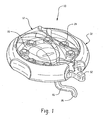
- FIGURE 1 is a perspective view of a dispenser according to the within invention.
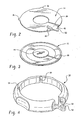
- FIGURE 2 is a perspective view of a product platform of a dispenser according to the within invention.
- FIGURE 3 is a perspective view of a base of a dispenser according to the within invention.
- FIGURE 4 is a perspective view of an exterior base of a dispenser according to the within invention.
- FIGURE 5A is a perspective view of a cover of a dispenser according to the within invention.
- FIGURE 5B is a bottom view of the cover of Fig. 2A.
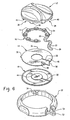
- FIGURE 6 is an exploded view of a dispenser according to the within invention.
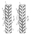
- FIGURE 7A is a view of the product platform and the adhesive strip according to one aspect of the within invention.
- FIGURE 7B is an alternate view of the product platform and the adhesive strip according to another aspect of the within invention.
- The specific embodiments illustrated in the appended drawings and described in the following specification are simply exemplary embodiments of the inventive concept defined in the appended claims. Hence, specific dimensions and physical characteristics relating to specific embodiments disclosed herein are not to be considered as limiting, unless the claims expressly state otherwise.
- The preferred embodiment of the
dispenser 10 of the within invention comprises aproduct platform 14, anadhesive strip 16 and aninterior base 18. Theadhesive strip 16 has two major opposingsurfaces surface 20 is an adhesive surface on whichproducts 24 exemplified herein as zinc air cells are affixed. Theother strip surface 22 is free of adhesive. Thestrip 16 is formed so as to coincide with the perimeter shape of theproduct platform 14. As illustrated herein, the product platform is round and theadhesive strip 16 is formed to enable positioning of the strip about a major portion of the circumference of theproduct platform 14. Thestrip 16 is placed on the upper surface of theproduct platform 14 so thatstrip surface 22 faces theproduct platform 14. Thestrip 16 is therefore not adhesively secured to the upper surface of theproduct platform 14, enabling relative motion between thestrip 16 and theproduct platform 14. - The leading
end 26 of theadhesive strip 16, defined herein as that end nearest to the first cell to be dispensed, is threaded through anopening 28 in theproduct platform 14. This assembly ofproduct platform 14 andadhesive strip 16 is joined to theinterior base 18 about a common axis of rotation in a manner that will enable relative motion between the product platform and theinterior base 18. The leadingend 26 ofstrip 16 is also fed through anopening 30 in theinterior base 18. The leadingend 26 ofstrip 16 is permanently affixed to theinterior base 18 on the undersurface thereof. - This assembly of the
strip 16 withproduct 24 affixed thereto, theproduct platform 14 and theinterior base 18 can release product from the adhesive strip and therefore dispense product in a single action. As more fully discussed herein, by causing the rotation of theproduct platform 14 with respect to theinterior base 18, or vice versa, so as to causeproduct 24 closest to theleading end 26 ofstrip 16 to encounter theopening 28 in theproduct platform 14,product 24 will be released from theadhesive surface 20 of thestrip 16. - In the preferred embodiment, the assembly of
product platform 14,strip 16,product 24 andinterior base 18 is then positioned within anexterior base 32. Theexterior base 32 serves to provide a convenient structure for gripping thedispenser 10 and for providing relative motion between theproduct platform 14 and theinterior base 18. Theproduct platform 14 and theexterior base 32 are joined such that they move together. For example, theexterior base 32 can be equipped with one or moreinternal indents 34 into whichprojections 36 on theproduct platform 14 will fit. Thus, theproduct platform 14 and theexterior base 32 will undergo the same relative motion with respect to theinterior base 18. Theexternal base 32 can optionally include indents along the outer perimeter to facilitate gripping, operation and manipulation of the dispenser. - Suitable materials for the
external base 32,product platform 14 andinternal base 18 include durable moldable polymer materials as are known in the art. Theadhesive strip 16 can be any adhesive material suitable for retaining product on the strip and in position within the dispenser during storage and shipping. In the case ofzinc air cells 28, the adhesive strip is preferably a suitable tabbing material as is used in the manufacture of zinc air cells. It will be appreciated that the selection of a suitable adhesive will be governed at least in part by the characteristics of the products that will be adhered to the adhesive strip and their anticipated storage, handling and shipping experience. - In the preferred embodiment, the dispenser further comprises a
cover 12. The cover comprises one ormore product chambers 38 formed bywalls 40 extending from the interior cover ceiling. When the cover is placed over theproduct platform 14 with theadhesive strip 16 and theproduct 24 in place, it will be appreciated that each product to be dispensed resides within oneproduct chamber 38. Thecover 12 and theinterior base 18 are joined such that they move together. For example, thecover 12 can be equipped with a projectingkey 42 that is positioned within a cooperatingkeyhole 44 located on theinterior base 18. Thus, thecover 12 and theinterior base 18 will undergo the same relative motion with respect to theproduct platform 14 and theexterior base 32. - Suitable materials for the cover include any durable moldable polymer material as is known in the art. Preferably, at least a portion of the cover is transparent to enable the product contained in the dispenser to be viewed by the user.
- During the rotation of the
cover 12 and theinterior base 18 with respect to theproduct platform 14 and theexterior base 32, theproduct 24 encounters theopening 28 in theproduct platform 14. Thestrip 16 passes through theopening 28 and is peeled from theproduct 24. The peeling action is caused by reversing the path of travel of the strip as it passes through theopening 28, so that the strip moves from a point over theproximal edge 58 of theopening 28, around theproximal edge 58 and to a point under the proximal edge of theopening 28. See Fig. 7A, showing just releasedproduct 24A and product to be released 24B, and the path of travel of thestrip 16. - Once the
product 24 has been released from thestrip 16, the product is available for dispensing by transitioning from the interior of the dispenser to the exterior of the dispenser. The continued rotation described above causes the released product to encounter theproduct chamber walls 40. It will be appreciated that the walls will be configured so as to cause the releasedproduct 24 to move towards a predeterminedproduct dispensing position 46 on theproduct platform 14 during the relative rotation motion described above. The configuration of the chamber walls will vary, depending in part on the shape of the product to be dispensed as well as the distance to be traveled by the released product following release from the adhesive strip. - In the preferred embodiment of the within invention, the
product platform 14 further comprises aproduct guide 48 and a transition landing 50, and theexterior base 32 further comprises anexternal landing 52. The single above described relative rotation movement causes theproduct 24 to be released from theadhesive strip 16, to move from theproduct dispensing position 46 onto the transition landing 50 and to move from the transition landing onto theexternal landing 52, thereby transferring product from the interior of the dispenser to the exterior of the dispenser. Theproduct guide 48 cooperates with thechamber walls 40 to move the released product into the appropriate position. The transition landing 50 is preferably integral with theproduct platform 14 and projects through an opening in the sidewall of theexterior base 32, thereby further preventing relative motion between theproduct platform 14 and theexternal base 32. - The
external landing 52 preferably comprises amagnetic component 54 secured to the landing. Themagnetic component 54 aids in controlling and removably maintaining metallic products such as zinc air batteries on the landing 52 while the user is orienting the product for final placement within a device or other disposition. Alternatively, as dictated by the product, other surfaces or materials, such as velcro or adhesives, may be utilized for controlling and removably maintaining products on the landing 52 as will be appreciated by those skilled in the art. These alternate surfaces or materials may comprise theentire landing 52 or may be secured to thelanding 52 via an adhesive or other securing method. Further, themagnetic component 54 can be planar or otherwise shaped, and may be exposed or embedded within the landing. Where product use and placement permit, the landing 52 may further include a stop wall (not shown) at the distal end of the landing to further control the forward motion of the product as it transitions from the interior of the dispenser onto the landing. - Removable retention of nonmetallic product on the landing can further be accomplished by extending an overhanging pincher (not shown) that extends over the landing 52 and results in a downward pressure on the
product 24, or by pinchers (not shown) on the landing itself that create an interference with theproduct 24 as it is dispensed onto the landing. - Optionally, indexing positions can be incorporated into the design of the dispenser of the within invention as is known in the art. Such indexing positions provide the user with a mechanical stopping point for the required rotation sufficient to release product from the adhesive strip and transfer product from the interior of the dispenser to the exterior of the dispenser. The underside of the base optionally comprises a storage compartment (not shown) for spent product storage.
- In another aspect of this embodiment of the within invention, the dispenser can be reused by discarding all or a portion of the assembly of the
product platform 14,strip 16 andinterior base 18 once all of theproduct 24 has been completely dispensed. A refill kit, comprising fresh product to be dispensed in a preassembled assembly comprising a product platform, strip, interior base and product is provided for re-introduction into the dispenser for use with theoriginal cover 12 andexterior base 32. - In an alternate method of employing the dispenser of the within invention, the adhesive strip is not peeled from the
product 24. Rather, the product is scrapped from the adhesive strip. In this method, the relative rotation motion of thecover 12 and theinterior base 18, on the one hand, and theproduct platform 14 and theexterior base 32, on the other hand, proceeds in the opposite direction, such that the path of travel of thestrip 16 upon passing through theproduct platform opening 28 is the same as its path of travel prior to passing through the opening. Thus, the rotation motion causes thedistal edge 56 of opening 28 to be interjected between thestrip 16 and theproduct 24 as the strip passes through theopening 28. In contrast to the peeling release mechanism described above, thestrip 16 does not pass over and around and under theproximal edge 58 of theopening 28. Rather, thestrip 16 moves from a point over theproximal edge 58 to a point under thedistal edge 56. See Fig. 7B, showing just releasedproduct 24A and product to be released 24B, and the path of travel of thestrip 16. - Although only a few embodiments of the present invention have been described above, it should be appreciated that many modifications can be made without departing from scope of the invention. The specification is intended to include modifications and alterations insofar as they come within the scope of the appended claims or the equivalents thereof.
Claims (20)
- A dispenser for transporting, housing and dispensing product, said dispenser comprising:a product platform comprising an opening through the platform;an adhesive strip comprising a leading end and two major surfaces with adhesive located onat least a portion of one of said two major surfaces;a base comprising an opening through the base,wherein said leading end is passed through the product platform opening, the base opening and attached to the base.
- The dispenser of claim 1, wherein said product platform and said base rotate about a common axis with respect to each other.
- The dispenser of claim 2, further comprising an exterior base having a sidewall and connected to said product platform so as to move with the product platform.
- The dispenser of claim 3, wherein said sidewall has an opening.
- The dispenser of claim 4, wherein said exterior base further comprises an external landing adjacent said sidewall opening.
- The dispenser of claim 5, wherein said external landing further comprises a magnet.
- The dispenser of claim 5, wherein said external landing further comprises one or more pinchers for creating an interference between the dispensed product and the said one or more pinchers.
- The dispenser of claim 6, wherein said product comprises one or more miniature zinc air cells.
- The dispenser of claim 5, further comprising a cover.
- The dispenser of claim 9, wherein said cover further comprises product chambers.
- The dispenser of claim 10, wherein said product platform further comprises a product guide.
- A method for dispensing product from a product dispenser, said method comprising:providing a product platform, product adhesively secured to an adhesive strip having a first end and a second end, and an interior base; providing an opening in said platform and said base; threading a first end of said strip through said platform opening and said base opening and securing said first end to the base; positioning said strip with affixed product onto one surface of the product platform; joining said platform and said base together such that they can rotate relative to each other about a common axis; and causing the rotation of said platform with respect to said base until said product is released from said adhesive strip.
- The method of claim 12, wherein said product is released from said adhesive strip by peeling said strip from said product.
- The method of claim 12, wherein said product is release from said adhesive strip by causing the interjection of an edge between said product and said strip.
- The method of claim 13, further comprising the steps of providing an exterior base joined to said product platform such that they move together, wherein said base further comprises a sidewall, an opening in said sidewall and an exterior landing adjacent said opening.
- The method of claim 15, further comprising the steps of providing a cover with one or more product chambers for moving product released from the strip from the interior of the dispenser onto the exterior landing.
- The method of claim 14, further comprising the steps of providing an exterior base joined to said product platform such that they move together, wherein said base further comprises a sidewall, an opening in said sidewall and an exterior landing adjacent said opening.
- The method of claim 17, further comprising the steps of providing a cover with one or more product chambers for moving product released from the strip from the interior of the dispenser onto the exterior landing.
- A refill kit for a product dispenser, said refill kit comprising a product platform, product adhesively secured to an adhesive strip having a first end and a second end, and an interior base; said platform and said base each further comprising an opening; said strip passing through said openings and said first end of said strip attached to said base; said strip with affixed product positioned onto one surface of the product platform; said platform and said base joined together such that they can rotate relative to each other about a common axis.
- The refill kit of claim 19, wherein said product comprises miniature zinc air cells.
Applications Claiming Priority (3)
| Application Number | Priority Date | Filing Date | Title |
|---|---|---|---|
| US336142 | 1994-11-08 | ||
| US10/336,142 US6769567B2 (en) | 2003-01-03 | 2003-01-03 | Product dispenser |
| PCT/US2003/040671 WO2004064179A2 (en) | 2003-01-03 | 2003-12-18 | Product dispenser |
Publications (2)
| Publication Number | Publication Date |
|---|---|
| EP1588441A2 EP1588441A2 (en) | 2005-10-26 |
| EP1588441B1 true EP1588441B1 (en) | 2006-05-03 |
Family
ID=32680941
Family Applications (1)
| Application Number | Title | Priority Date | Filing Date |
|---|---|---|---|
| EP03815231A Expired - Lifetime EP1588441B1 (en) | 2003-01-03 | 2003-12-18 | Product dispenser |
Country Status (10)
| Country | Link |
|---|---|
| US (1) | US6769567B2 (en) |
| EP (1) | EP1588441B1 (en) |
| JP (1) | JP4225977B2 (en) |
| CN (1) | CN100346502C (en) |
| AT (1) | ATE325432T1 (en) |
| AU (1) | AU2003301140B2 (en) |
| DE (1) | DE60305080T2 (en) |
| NZ (1) | NZ540765A (en) |
| WO (1) | WO2004064179A2 (en) |
| ZA (1) | ZA200504931B (en) |
Families Citing this family (11)
| Publication number | Priority date | Publication date | Assignee | Title |
|---|---|---|---|---|
| US7232041B2 (en) * | 2004-10-29 | 2007-06-19 | Eveready Battery Company | Battery dispenser and refill |
| US7461760B2 (en) * | 2004-10-29 | 2008-12-09 | Eveready Battery Company, Inc. | Battery dispenser and refill |
| US20060124658A1 (en) * | 2004-12-10 | 2006-06-15 | Coe Matthew T | Pill dispenser with patient compliant indicating means |
| WO2008049172A1 (en) * | 2006-10-27 | 2008-05-02 | Vision Biosystems Limited | A method and apparatus for dispensing substrates |
| US7946448B1 (en) | 2008-09-30 | 2011-05-24 | John Madey | Pill dispenser |
| KR20110137357A (en) * | 2009-03-13 | 2011-12-22 | 산노바 가부시키가이샤 | Card Package |
| WO2011115762A1 (en) * | 2010-03-18 | 2011-09-22 | Eveready Battery Company, Inc. | Button cell battery dispenser package |
| US9209442B1 (en) * | 2014-06-09 | 2015-12-08 | Akoio, Llc | Product dispenser |
| WO2020124051A1 (en) * | 2018-12-14 | 2020-06-18 | Energizer Brands, Llc | Zinc-air electrochemical cells with carbon dioxide scavangers |
| US12486084B2 (en) * | 2023-08-02 | 2025-12-02 | Hangzhou Yici Chengpin Technology Co., Ltd. | Packaging cover and packaging container |
| US12490819B1 (en) | 2025-06-11 | 2025-12-09 | Little Nest Solutions LLC | Small object storage apparatus |
Family Cites Families (45)
| Publication number | Priority date | Publication date | Assignee | Title |
|---|---|---|---|---|
| US610522A (en) * | 1898-09-13 | Paper box | ||
| US1116043A (en) * | 1912-10-31 | 1914-11-03 | William Elijah Elliott | Carton for merchandise. |
| US2359679A (en) * | 1942-03-10 | 1944-10-03 | Gen Aniline & Film Corp | Film carton with mailing tag |
| US2790587A (en) * | 1954-10-18 | 1957-04-30 | Hoffmann La Roche | Box |
| US3187889A (en) * | 1961-05-08 | 1965-06-08 | Gillette Co | Package for article of merchandise |
| US3394796A (en) * | 1967-07-25 | 1968-07-30 | Warren R. Jensen | Pill dispenser |
| US3476239A (en) * | 1967-09-06 | 1969-11-04 | Continental Can Co | Blister package and product thereof |
| US3437236A (en) * | 1967-09-26 | 1969-04-08 | Ortho Pharma Corp | Tablet dispensing device |
| US3633792A (en) * | 1969-11-17 | 1972-01-11 | Beltone Electronics Corp | Small article dispenser |
| US3897265A (en) * | 1974-01-30 | 1975-07-29 | Gte Laboratories Inc | Electrochemical cells |
| US3881257A (en) * | 1974-07-16 | 1975-05-06 | Coats & Clark | Levelling device including merchandise dispensing means |
| CA1032511A (en) * | 1974-10-15 | 1978-06-06 | Robert E. Brindley | Battery dispenser |
| US3990578A (en) * | 1974-10-25 | 1976-11-09 | Packaging Corporation Of America | Foldable display package |
| US4015708A (en) * | 1975-11-21 | 1977-04-05 | Gould Inc. | Button cell storage and merchandising package |
| US4124143A (en) * | 1977-02-11 | 1978-11-07 | Ryder International Corporation | Pill dispenser |
| US4209091A (en) * | 1978-08-10 | 1980-06-24 | Gould Inc. | Button cell package and method of making same |
| GB2071618B (en) | 1980-03-19 | 1983-11-09 | Duracell Int | Battery dispenser |
| US4591539A (en) * | 1983-06-23 | 1986-05-27 | Rayovac Corporation | Metal-air cathode button cell |
| US4696402A (en) * | 1985-03-19 | 1987-09-29 | Rayovac Corporation | Easy-open, individual unit dispensing package |
| US4649090A (en) * | 1986-01-22 | 1987-03-10 | Rayovac Corporation | Seal tab for a metal-air electrochemical cell |
| US4791034A (en) * | 1987-02-10 | 1988-12-13 | Rayovac Corporation | Sealing sleeve |
| US4860890A (en) * | 1988-08-31 | 1989-08-29 | Beltone Electronics Corporation | Battery holder |
| CH678713A5 (en) * | 1989-05-18 | 1991-10-31 | Renata Ag | |
| DE3921674C1 (en) * | 1989-07-01 | 1990-10-31 | Ralston Energy Systems Deutschland Gmbh, 4006 Erkrath, De | |
| US4953700A (en) * | 1990-02-07 | 1990-09-04 | The Shelby Paper Box Company | Display card for a battery package |
| US5119952A (en) | 1990-08-30 | 1992-06-09 | Warriner Jr Watson C | Postcard-type package for flowable substances |
| US5117977A (en) * | 1991-05-24 | 1992-06-02 | Bausch & Lomb Hearing Systems Division, Inc. | Small battery dispensing, insertion and removal apparatus |
| DE4128248A1 (en) * | 1991-08-26 | 1993-03-04 | Varta Batterie | SALES AND STOCK PACK FOR ZINC / AIR CELLS |
| US5199565A (en) * | 1991-11-04 | 1993-04-06 | Bausch & Lomb Incorporated | Small battery dispensing and removal apparatus |
| US5308711A (en) * | 1993-02-09 | 1994-05-03 | Rayovac Corporation | Metal-air cathode and cell having catalytically active manganese compounds of valence state +2 |
| US5404105A (en) * | 1993-07-12 | 1995-04-04 | Chari; Nallan C. A. | Multipurpose hearing aid maintenance device |
| US5477981A (en) * | 1994-04-22 | 1995-12-26 | Excerpta Medica, Inc. | Twist article dispenser |
| US5562231A (en) * | 1994-07-29 | 1996-10-08 | Ortho Pharmaceutical Corporation | Variable day start tablet dispenser |
| US5611456A (en) * | 1995-01-24 | 1997-03-18 | Algonquin Industries Inc. | Apparatus for dispensing tickets, cards and the like |
| US5795667A (en) * | 1995-05-05 | 1998-08-18 | Rayovac Corporation | Metal-air cathode can, and electrochemical cell made therewith |
| US5591541A (en) * | 1995-05-05 | 1997-01-07 | Rayovac Corporation | High steel content thin walled anode can |
| US5839583A (en) * | 1997-06-25 | 1998-11-24 | Duracell Batteries, Ltd. | Packaging |
| CA2212112A1 (en) | 1997-08-18 | 1999-02-18 | Claude Richard | Package and blank for making the same |
| NL1009878C2 (en) * | 1998-08-17 | 2000-02-18 | Npk Ind Design B V | Device for dispensing pills, as well as a dispenser and blister pack for use therein. |
| US6039185A (en) * | 1998-12-14 | 2000-03-21 | Rayovac Corporation | Hearing aid battery inserter |
| US6164490A (en) * | 1999-05-03 | 2000-12-26 | Northeast Iowa Rehabilitation Agency | Storage and dispensing package for batteries and other objects |
| WO2001087732A1 (en) * | 2000-05-15 | 2001-11-22 | Eveready Battery Company, Inc. | Product dispenser and method of making same |
| US6581799B1 (en) * | 2000-09-08 | 2003-06-24 | Eveready Battery Company, Inc. | Product dispenser |
| US6631825B2 (en) | 2000-09-08 | 2003-10-14 | Eveready Battery Company, Inc. | Product dispenser |
| US6329095B1 (en) * | 2000-10-19 | 2001-12-11 | The Gillette Company | Tab for zinc/air cell |
-
2003
- 2003-01-03 US US10/336,142 patent/US6769567B2/en not_active Expired - Lifetime
- 2003-12-18 CN CNB200380108248XA patent/CN100346502C/en not_active Expired - Lifetime
- 2003-12-18 WO PCT/US2003/040671 patent/WO2004064179A2/en not_active Ceased
- 2003-12-18 JP JP2004566579A patent/JP4225977B2/en not_active Expired - Fee Related
- 2003-12-18 DE DE60305080T patent/DE60305080T2/en not_active Expired - Lifetime
- 2003-12-18 NZ NZ540765A patent/NZ540765A/en unknown
- 2003-12-18 EP EP03815231A patent/EP1588441B1/en not_active Expired - Lifetime
- 2003-12-18 AU AU2003301140A patent/AU2003301140B2/en not_active Ceased
- 2003-12-18 AT AT03815231T patent/ATE325432T1/en not_active IP Right Cessation
-
2005
- 2005-06-17 ZA ZA200504931A patent/ZA200504931B/en unknown
Also Published As
| Publication number | Publication date |
|---|---|
| JP2006513931A (en) | 2006-04-27 |
| US6769567B2 (en) | 2004-08-03 |
| AU2003301140B2 (en) | 2006-09-14 |
| DE60305080T2 (en) | 2007-04-26 |
| AU2003301140A1 (en) | 2004-08-10 |
| US20040129717A1 (en) | 2004-07-08 |
| CN100346502C (en) | 2007-10-31 |
| HK1084239A1 (en) | 2006-07-21 |
| NZ540765A (en) | 2006-03-31 |
| ATE325432T1 (en) | 2006-06-15 |
| DE60305080D1 (en) | 2006-06-08 |
| EP1588441A2 (en) | 2005-10-26 |
| WO2004064179A2 (en) | 2004-07-29 |
| JP4225977B2 (en) | 2009-02-18 |
| WO2004064179A3 (en) | 2005-04-14 |
| ZA200504931B (en) | 2006-04-26 |
| CN1735981A (en) | 2006-02-15 |
Similar Documents
| Publication | Publication Date | Title |
|---|---|---|
| US6488176B2 (en) | Product dispenser | |
| US6631825B2 (en) | Product dispenser | |
| EP1588441B1 (en) | Product dispenser | |
| AU2001288802A1 (en) | Product dispenser | |
| US5199565A (en) | Small battery dispensing and removal apparatus | |
| CN107810150B (en) | Hearing aid battery package | |
| HK175995A (en) | Sales and storage package for zinc/air batteries | |
| US20160090233A1 (en) | Product Dispenser | |
| US5117977A (en) | Small battery dispensing, insertion and removal apparatus | |
| HK1084239B (en) | Product dispenser | |
| US7232041B2 (en) | Battery dispenser and refill | |
| US10490784B2 (en) | Wearable battery storage apparatus and system | |
| JP2005015047A (en) | Chewing gum container equipped with attaching/ detaching means | |
| AU2005302598B2 (en) | Battery dispenser and refill | |
| US10573858B2 (en) | Wearable battery storage apparatus and system with replaceable battery cartridge | |
| HK1056860B (en) | Product dispenser | |
| JP2537787Y2 (en) | Label for package lid | |
| JP4933021B2 (en) | Product dispenser |
Legal Events
| Date | Code | Title | Description |
|---|---|---|---|
| PUAI | Public reference made under article 153(3) epc to a published international application that has entered the european phase |
Free format text: ORIGINAL CODE: 0009012 |
|
| 17P | Request for examination filed |
Effective date: 20050610 |
|
| AK | Designated contracting states |
Kind code of ref document: A2 Designated state(s): AT BE BG CH CY CZ DE DK EE ES FI FR GB GR HU IE IT LI LU MC NL PT RO SE SI SK TR |
|
| AX | Request for extension of the european patent |
Extension state: AL LT LV MK |
|
| GRAP | Despatch of communication of intention to grant a patent |
Free format text: ORIGINAL CODE: EPIDOSNIGR1 |
|
| GRAS | Grant fee paid |
Free format text: ORIGINAL CODE: EPIDOSNIGR3 |
|
| GRAA | (expected) grant |
Free format text: ORIGINAL CODE: 0009210 |
|
| DAX | Request for extension of the european patent (deleted) | ||
| AK | Designated contracting states |
Kind code of ref document: B1 Designated state(s): AT BE BG CH CY CZ DE DK EE ES FI FR GB GR HU IE IT LI LU MC NL PT RO SE SI SK TR |
|
| PG25 | Lapsed in a contracting state [announced via postgrant information from national office to epo] |
Ref country code: IT Free format text: LAPSE BECAUSE OF FAILURE TO SUBMIT A TRANSLATION OF THE DESCRIPTION OR TO PAY THE FEE WITHIN THE PRESCRIBED TIME-LIMIT;WARNING: LAPSES OF ITALIAN PATENTS WITH EFFECTIVE DATE BEFORE 2007 MAY HAVE OCCURRED AT ANY TIME BEFORE 2007. THE CORRECT EFFECTIVE DATE MAY BE DIFFERENT FROM THE ONE RECORDED. Effective date: 20060503 Ref country code: FI Free format text: LAPSE BECAUSE OF FAILURE TO SUBMIT A TRANSLATION OF THE DESCRIPTION OR TO PAY THE FEE WITHIN THE PRESCRIBED TIME-LIMIT Effective date: 20060503 Ref country code: SK Free format text: LAPSE BECAUSE OF FAILURE TO SUBMIT A TRANSLATION OF THE DESCRIPTION OR TO PAY THE FEE WITHIN THE PRESCRIBED TIME-LIMIT Effective date: 20060503 Ref country code: NL Free format text: LAPSE BECAUSE OF FAILURE TO SUBMIT A TRANSLATION OF THE DESCRIPTION OR TO PAY THE FEE WITHIN THE PRESCRIBED TIME-LIMIT Effective date: 20060503 Ref country code: SI Free format text: LAPSE BECAUSE OF FAILURE TO SUBMIT A TRANSLATION OF THE DESCRIPTION OR TO PAY THE FEE WITHIN THE PRESCRIBED TIME-LIMIT Effective date: 20060503 Ref country code: AT Free format text: LAPSE BECAUSE OF FAILURE TO SUBMIT A TRANSLATION OF THE DESCRIPTION OR TO PAY THE FEE WITHIN THE PRESCRIBED TIME-LIMIT Effective date: 20060503 Ref country code: CZ Free format text: LAPSE BECAUSE OF FAILURE TO SUBMIT A TRANSLATION OF THE DESCRIPTION OR TO PAY THE FEE WITHIN THE PRESCRIBED TIME-LIMIT Effective date: 20060503 Ref country code: RO Free format text: LAPSE BECAUSE OF FAILURE TO SUBMIT A TRANSLATION OF THE DESCRIPTION OR TO PAY THE FEE WITHIN THE PRESCRIBED TIME-LIMIT Effective date: 20060503 |
|
| REG | Reference to a national code |
Ref country code: GB Ref legal event code: FG4D |
|
| REG | Reference to a national code |
Ref country code: CH Ref legal event code: EP |
|
| REF | Corresponds to: |
Ref document number: 60305080 Country of ref document: DE Date of ref document: 20060608 Kind code of ref document: P |
|
| REG | Reference to a national code |
Ref country code: IE Ref legal event code: FG4D |
|
| REG | Reference to a national code |
Ref country code: HK Ref legal event code: DE Ref document number: 1084239 Country of ref document: HK |
|
| PG25 | Lapsed in a contracting state [announced via postgrant information from national office to epo] |
Ref country code: SE Free format text: LAPSE BECAUSE OF FAILURE TO SUBMIT A TRANSLATION OF THE DESCRIPTION OR TO PAY THE FEE WITHIN THE PRESCRIBED TIME-LIMIT Effective date: 20060803 Ref country code: DK Free format text: LAPSE BECAUSE OF FAILURE TO SUBMIT A TRANSLATION OF THE DESCRIPTION OR TO PAY THE FEE WITHIN THE PRESCRIBED TIME-LIMIT Effective date: 20060803 |
|
| PG25 | Lapsed in a contracting state [announced via postgrant information from national office to epo] |
Ref country code: ES Free format text: LAPSE BECAUSE OF FAILURE TO SUBMIT A TRANSLATION OF THE DESCRIPTION OR TO PAY THE FEE WITHIN THE PRESCRIBED TIME-LIMIT Effective date: 20060814 |
|
| REG | Reference to a national code |
Ref country code: CH Ref legal event code: NV Representative=s name: A. BRAUN, BRAUN, HERITIER, ESCHMANN AG PATENTANWAE |
|
| PG25 | Lapsed in a contracting state [announced via postgrant information from national office to epo] |
Ref country code: PT Free format text: LAPSE BECAUSE OF FAILURE TO SUBMIT A TRANSLATION OF THE DESCRIPTION OR TO PAY THE FEE WITHIN THE PRESCRIBED TIME-LIMIT Effective date: 20061003 |
|
| NLV1 | Nl: lapsed or annulled due to failure to fulfill the requirements of art. 29p and 29m of the patents act | ||
| REG | Reference to a national code |
Ref country code: HK Ref legal event code: GR Ref document number: 1084239 Country of ref document: HK |
|
| PG25 | Lapsed in a contracting state [announced via postgrant information from national office to epo] |
Ref country code: IE Free format text: LAPSE BECAUSE OF NON-PAYMENT OF DUE FEES Effective date: 20061218 |
|
| PG25 | Lapsed in a contracting state [announced via postgrant information from national office to epo] |
Ref country code: MC Free format text: LAPSE BECAUSE OF NON-PAYMENT OF DUE FEES Effective date: 20061231 |
|
| PLBE | No opposition filed within time limit |
Free format text: ORIGINAL CODE: 0009261 |
|
| STAA | Information on the status of an ep patent application or granted ep patent |
Free format text: STATUS: NO OPPOSITION FILED WITHIN TIME LIMIT |
|
| 26N | No opposition filed |
Effective date: 20070206 |
|
| EN | Fr: translation not filed | ||
| PG25 | Lapsed in a contracting state [announced via postgrant information from national office to epo] |
Ref country code: GR Free format text: LAPSE BECAUSE OF FAILURE TO SUBMIT A TRANSLATION OF THE DESCRIPTION OR TO PAY THE FEE WITHIN THE PRESCRIBED TIME-LIMIT Effective date: 20060804 Ref country code: FR Free format text: LAPSE BECAUSE OF FAILURE TO SUBMIT A TRANSLATION OF THE DESCRIPTION OR TO PAY THE FEE WITHIN THE PRESCRIBED TIME-LIMIT Effective date: 20070309 |
|
| REG | Reference to a national code |
Ref country code: CH Ref legal event code: PFA Owner name: EVEREADY BATTERY COMPANY, INC. Free format text: EVEREADY BATTERY COMPANY, INC.#533 MARYVILLE UNIVERSITY DRIVE#ST. LOUIS, MO 63141 (US) -TRANSFER TO- EVEREADY BATTERY COMPANY, INC.#533 MARYVILLE UNIVERSITY DRIVE#ST. LOUIS, MO 63141 (US) |
|
| PG25 | Lapsed in a contracting state [announced via postgrant information from national office to epo] |
Ref country code: EE Free format text: LAPSE BECAUSE OF FAILURE TO SUBMIT A TRANSLATION OF THE DESCRIPTION OR TO PAY THE FEE WITHIN THE PRESCRIBED TIME-LIMIT Effective date: 20060503 Ref country code: BG Free format text: LAPSE BECAUSE OF FAILURE TO SUBMIT A TRANSLATION OF THE DESCRIPTION OR TO PAY THE FEE WITHIN THE PRESCRIBED TIME-LIMIT Effective date: 20060803 |
|
| PG25 | Lapsed in a contracting state [announced via postgrant information from national office to epo] |
Ref country code: LU Free format text: LAPSE BECAUSE OF NON-PAYMENT OF DUE FEES Effective date: 20061218 Ref country code: HU Free format text: LAPSE BECAUSE OF FAILURE TO SUBMIT A TRANSLATION OF THE DESCRIPTION OR TO PAY THE FEE WITHIN THE PRESCRIBED TIME-LIMIT Effective date: 20061104 Ref country code: TR Free format text: LAPSE BECAUSE OF FAILURE TO SUBMIT A TRANSLATION OF THE DESCRIPTION OR TO PAY THE FEE WITHIN THE PRESCRIBED TIME-LIMIT Effective date: 20060503 |
|
| PG25 | Lapsed in a contracting state [announced via postgrant information from national office to epo] |
Ref country code: FR Free format text: LAPSE BECAUSE OF FAILURE TO SUBMIT A TRANSLATION OF THE DESCRIPTION OR TO PAY THE FEE WITHIN THE PRESCRIBED TIME-LIMIT Effective date: 20060503 Ref country code: CY Free format text: LAPSE BECAUSE OF FAILURE TO SUBMIT A TRANSLATION OF THE DESCRIPTION OR TO PAY THE FEE WITHIN THE PRESCRIBED TIME-LIMIT Effective date: 20060503 |
|
| PGFP | Annual fee paid to national office [announced via postgrant information from national office to epo] |
Ref country code: GB Payment date: 20131227 Year of fee payment: 11 Ref country code: CH Payment date: 20131230 Year of fee payment: 11 |
|
| PGFP | Annual fee paid to national office [announced via postgrant information from national office to epo] |
Ref country code: BE Payment date: 20131227 Year of fee payment: 11 |
|
| REG | Reference to a national code |
Ref country code: CH Ref legal event code: PCAR Free format text: NEW ADDRESS: HOLBEINSTRASSE 36-38, 4051 BASEL (CH) |
|
| PG25 | Lapsed in a contracting state [announced via postgrant information from national office to epo] |
Ref country code: BE Free format text: LAPSE BECAUSE OF NON-PAYMENT OF DUE FEES Effective date: 20141231 |
|
| REG | Reference to a national code |
Ref country code: CH Ref legal event code: PL |
|
| GBPC | Gb: european patent ceased through non-payment of renewal fee |
Effective date: 20141218 |
|
| REG | Reference to a national code |
Ref country code: DE Ref legal event code: R082 Ref document number: 60305080 Country of ref document: DE Representative=s name: VON KREISLER SELTING WERNER - PARTNERSCHAFT VO, DE Ref country code: DE Ref legal event code: R081 Ref document number: 60305080 Country of ref document: DE Owner name: ENERGIZER BRANDS, LLC (N.D.GES.D. STAATES DELA, US Free format text: FORMER OWNER: EVEREADY BATTERY CO., INC., ST. LOUIS, MO., US Ref country code: DE Ref legal event code: R082 Ref document number: 60305080 Country of ref document: DE Representative=s name: DOMPATENT VON KREISLER SELTING WERNER - PARTNE, DE |
|
| PG25 | Lapsed in a contracting state [announced via postgrant information from national office to epo] |
Ref country code: CH Free format text: LAPSE BECAUSE OF NON-PAYMENT OF DUE FEES Effective date: 20141231 Ref country code: GB Free format text: LAPSE BECAUSE OF NON-PAYMENT OF DUE FEES Effective date: 20141218 Ref country code: LI Free format text: LAPSE BECAUSE OF NON-PAYMENT OF DUE FEES Effective date: 20141231 |
|
| PGFP | Annual fee paid to national office [announced via postgrant information from national office to epo] |
Ref country code: DE Payment date: 20171212 Year of fee payment: 15 |
|
| REG | Reference to a national code |
Ref country code: DE Ref legal event code: R119 Ref document number: 60305080 Country of ref document: DE |
|
| PG25 | Lapsed in a contracting state [announced via postgrant information from national office to epo] |
Ref country code: DE Free format text: LAPSE BECAUSE OF NON-PAYMENT OF DUE FEES Effective date: 20190702 |