EP1588065B1 - Damper bearings - Google Patents
Damper bearings Download PDFInfo
- Publication number
- EP1588065B1 EP1588065B1 EP04700990A EP04700990A EP1588065B1 EP 1588065 B1 EP1588065 B1 EP 1588065B1 EP 04700990 A EP04700990 A EP 04700990A EP 04700990 A EP04700990 A EP 04700990A EP 1588065 B1 EP1588065 B1 EP 1588065B1
- Authority
- EP
- European Patent Office
- Prior art keywords
- insert
- housing
- iii
- din
- article
- Prior art date
- Legal status (The legal status is an assumption and is not a legal conclusion. Google has not performed a legal analysis and makes no representation as to the accuracy of the status listed.)
- Expired - Lifetime
Links
- 229920002803 thermoplastic polyurethane Polymers 0.000 claims abstract description 17
- 239000004433 Thermoplastic polyurethane Substances 0.000 claims abstract description 16
- 230000001413 cellular effect Effects 0.000 claims description 9
- 238000010276 construction Methods 0.000 claims description 9
- 229920003225 polyurethane elastomer Polymers 0.000 claims description 6
- 238000013016 damping Methods 0.000 description 8
- 230000035939 shock Effects 0.000 description 8
- 239000006096 absorbing agent Substances 0.000 description 7
- 229920001971 elastomer Polymers 0.000 description 6
- 239000000806 elastomer Substances 0.000 description 6
- 229920001228 polyisocyanate Polymers 0.000 description 6
- 239000005056 polyisocyanate Substances 0.000 description 6
- -1 polyoxymethylene Polymers 0.000 description 5
- 238000012360 testing method Methods 0.000 description 5
- XEEYBQQBJWHFJM-UHFFFAOYSA-N Iron Chemical compound [Fe] XEEYBQQBJWHFJM-UHFFFAOYSA-N 0.000 description 4
- 239000000463 material Substances 0.000 description 4
- 238000000034 method Methods 0.000 description 4
- 229910052751 metal Inorganic materials 0.000 description 3
- 239000002184 metal Substances 0.000 description 3
- 238000002360 preparation method Methods 0.000 description 3
- 229930040373 Paraformaldehyde Natural products 0.000 description 2
- 239000004952 Polyamide Substances 0.000 description 2
- 229910000831 Steel Inorganic materials 0.000 description 2
- 229910052782 aluminium Inorganic materials 0.000 description 2
- XAGFODPZIPBFFR-UHFFFAOYSA-N aluminium Chemical compound [Al] XAGFODPZIPBFFR-UHFFFAOYSA-N 0.000 description 2
- 230000005540 biological transmission Effects 0.000 description 2
- 229910052742 iron Inorganic materials 0.000 description 2
- 150000002739 metals Chemical class 0.000 description 2
- 229920003023 plastic Polymers 0.000 description 2
- 239000004033 plastic Substances 0.000 description 2
- 229920002647 polyamide Polymers 0.000 description 2
- 229920006324 polyoxymethylene Polymers 0.000 description 2
- 229920001296 polysiloxane Polymers 0.000 description 2
- 230000000284 resting effect Effects 0.000 description 2
- 239000010959 steel Substances 0.000 description 2
- XLYOFNOQVPJJNP-UHFFFAOYSA-N water Chemical compound O XLYOFNOQVPJJNP-UHFFFAOYSA-N 0.000 description 2
- OWIKHYCFFJSOEH-UHFFFAOYSA-N Isocyanic acid Chemical compound N=C=O OWIKHYCFFJSOEH-UHFFFAOYSA-N 0.000 description 1
- 229920002396 Polyurea Polymers 0.000 description 1
- 239000000654 additive Substances 0.000 description 1
- 239000003054 catalyst Substances 0.000 description 1
- 150000001875 compounds Chemical class 0.000 description 1
- 230000006835 compression Effects 0.000 description 1
- 238000007906 compression Methods 0.000 description 1
- 235000014113 dietary fatty acids Nutrition 0.000 description 1
- 229930195729 fatty acid Natural products 0.000 description 1
- 239000000194 fatty acid Substances 0.000 description 1
- 238000001746 injection moulding Methods 0.000 description 1
- 239000012948 isocyanate Substances 0.000 description 1
- 150000002513 isocyanates Chemical class 0.000 description 1
- 230000000704 physical effect Effects 0.000 description 1
- 229920002635 polyurethane Polymers 0.000 description 1
- 239000004814 polyurethane Substances 0.000 description 1
- 239000003380 propellant Substances 0.000 description 1
- 238000007789 sealing Methods 0.000 description 1
- 239000004447 silicone coating Substances 0.000 description 1
- 239000007858 starting material Substances 0.000 description 1
- 239000000725 suspension Substances 0.000 description 1
Images


Classifications
-
- F—MECHANICAL ENGINEERING; LIGHTING; HEATING; WEAPONS; BLASTING
- F16—ENGINEERING ELEMENTS AND UNITS; GENERAL MEASURES FOR PRODUCING AND MAINTAINING EFFECTIVE FUNCTIONING OF MACHINES OR INSTALLATIONS; THERMAL INSULATION IN GENERAL
- F16C—SHAFTS; FLEXIBLE SHAFTS; ELEMENTS OR CRANKSHAFT MECHANISMS; ROTARY BODIES OTHER THAN GEARING ELEMENTS; BEARINGS
- F16C27/00—Elastic or yielding bearings or bearing supports, for exclusively rotary movement
- F16C27/06—Elastic or yielding bearings or bearing supports, for exclusively rotary movement by means of parts of rubber or like materials
-
- F—MECHANICAL ENGINEERING; LIGHTING; HEATING; WEAPONS; BLASTING
- F16—ENGINEERING ELEMENTS AND UNITS; GENERAL MEASURES FOR PRODUCING AND MAINTAINING EFFECTIVE FUNCTIONING OF MACHINES OR INSTALLATIONS; THERMAL INSULATION IN GENERAL
- F16C—SHAFTS; FLEXIBLE SHAFTS; ELEMENTS OR CRANKSHAFT MECHANISMS; ROTARY BODIES OTHER THAN GEARING ELEMENTS; BEARINGS
- F16C27/00—Elastic or yielding bearings or bearing supports, for exclusively rotary movement
- F16C27/08—Elastic or yielding bearings or bearing supports, for exclusively rotary movement primarily for axial load, e.g. for vertically-arranged shafts
-
- F—MECHANICAL ENGINEERING; LIGHTING; HEATING; WEAPONS; BLASTING
- F16—ENGINEERING ELEMENTS AND UNITS; GENERAL MEASURES FOR PRODUCING AND MAINTAINING EFFECTIVE FUNCTIONING OF MACHINES OR INSTALLATIONS; THERMAL INSULATION IN GENERAL
- F16F—SPRINGS; SHOCK-ABSORBERS; MEANS FOR DAMPING VIBRATION
- F16F1/00—Springs
- F16F1/36—Springs made of rubber or other material having high internal friction, e.g. thermoplastic elastomers
- F16F1/373—Springs made of rubber or other material having high internal friction, e.g. thermoplastic elastomers characterised by having a particular shape
- F16F1/3732—Springs made of rubber or other material having high internal friction, e.g. thermoplastic elastomers characterised by having a particular shape having an annular or the like shape, e.g. grommet-type resilient mountings
-
- F—MECHANICAL ENGINEERING; LIGHTING; HEATING; WEAPONS; BLASTING
- F16—ENGINEERING ELEMENTS AND UNITS; GENERAL MEASURES FOR PRODUCING AND MAINTAINING EFFECTIVE FUNCTIONING OF MACHINES OR INSTALLATIONS; THERMAL INSULATION IN GENERAL
- F16F—SPRINGS; SHOCK-ABSORBERS; MEANS FOR DAMPING VIBRATION
- F16F9/00—Springs, vibration-dampers, shock-absorbers, or similarly-constructed movement-dampers using a fluid or the equivalent as damping medium
- F16F9/32—Details
- F16F9/54—Arrangements for attachment
Definitions
- the invention relates to damper bearings, in particular round bearing containing at least one preferably flat preferably cylindrical preferably provided with a central bore insert (i), which is positioned in a preferably cylindrical housing (ii), at least two preferably two preferably cylindrical preferably annular preferably elastic bearing elements (iii ) positioned above and below the insert (i) and preferably resting against the insert and between insert (i) and housing (ii) preferably in contact with the insert (i) and the housing (ii) at least one preferably annular one Article (iv) based on thermoplastic polyurethane.
- the invention relates to spring structures, in particular for mounting and fastening the piston rod of an automobile shock absorber containing a piston rod (x) at the end of a preferably flat preferably cylindrical preferably provided with a central bore insert (i) is attached, preferably with a nut (v ), which is in a preferably cylindrical housing (ii), which has a lateral edge (vi) and a lower edge (vii) and whose upper opening is partially or completely preferably closed by a cover (viii), optionally with a sealing ring (xi) between the cover (viii) and housing (ii), and below the lower edge (vii) of the housing a hollow cylindrical auxiliary spring (ix) enclosing the piston rod (x), wherein above and below the insert (i ), preferably between the insert (i) and the lower edge (vii) of the housing (ii) and between insert (i) and the teilw or completely closed opening of the housing, preferably the cover (viii), in each case at least one preferably cylindrical preferably annular
- Damper bearings are used in automobiles within the chassis, for example, for connecting the piston rod of the shock absorber to the body of the automobile and in the storage of aggregates and are well known.
- damper bearings are in Automobile units, such as engine, transmission, air compressor, compressor, or chassis components, eg subframe bearings, leaf spring bearings, handlebars, among others, or connected to the body. They fulfill the function of an elastic storage by the use of elastomeric materials; On the other hand, because of their viscous properties, they are able to dissipate energy and thus dampen vibrations.
- a high degree of damping is particularly needed for the damping large-ßer amplitudes of low-frequency vibrations, for example, affect the connection of the shock absorber to the body.
- high damping is undesirable for reasons of vehicle acoustics.
- the damping behavior of current, conventional round bearings depends on the material-inherent damping capacity of the elastomer material used.
- German utility model 020213260 describes damper bearings, according to the preamble of claim 1, in which both a radially acting damping element and a sliding sleeve are present between the insert and the outer sleeve.
- the sliding sleeve should ensure the axial mobility of the radially damping element.
- Object of the present invention was to develop damper bearings, in particular spring structures for connecting the piston rod of the automobile shock absorber to the automobile body, in which a certain deformation can be realized with different defined starting stiffness in the radial and axial directions.
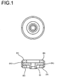
- FIG. 3 illustrates the article (iv), in this preferred case a ring.
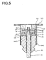
- FIG. 5 shows, by way of example, a spring construction according to the invention. In all figures, the dimensions are given in [mm].
- the preferably cylindrical insert (i) can be constructed in one or more parts and based on conventional materials, for example metals, for example steel, iron and / or aluminum or hard plastics, for example thermoplastic polyurethane (TPU), polyoxymethylene and / or polyamide.
- the insert (i) preferably has an inner bore usually for receiving a fastening bolt.
- the outer diameter results from structural reasons.
- the insert (i) as shown in Figure 2 has a diameter (xx) of 40 mm to 60 mm, more preferably 50 mm to 55 mm.
- the height (xxi) of the inserter (i) is preferably 10 mm to 20 mm, particularly preferably 15 mm.
- the diameter (xxii) of the bore in the insert (i) is preferably 8 mm to 15 mm, particularly preferably 10 mm to 11 mm.
- the height (xxiii) of the edge of the inserter (i) is preferably 5 mm to 7 mm.
- the housing (ii) can be of one or more parts, preferably of one-piece construction and based on conventional materials, for example metals, e.g. Steel, iron and / or aluminum or hard plastics, e.g. TPU, polyoxymethylene and / or polyamide.
- the housing (ii) has an outer diameter and an inner diameter, which may vary in dimensions and designs.
- the invention includes both calibrated and uncalibrated housings (ii). A fixation of the items, i. Inserter (iii), bearing element (iii), article (iv) and housing (ii) can be achieved for example by calibration.
- the cellular polyisocyanate polyaddition products preferably have a compression set of less than 25% according to DIN 53572, using cubes measuring 40 mm.times.40 mm.times.30 mm without silicone coating as the test specimen, the test being carried out with constant deformation, the specimens being compressed by 40% and 22 hours at 80 ° C in a convection oven, the test device is cooled after removal from the oven for 2 hours in the compressed state to room temperature, then the specimen is removed from the tester and 10 min ⁇ 30 s after removal of the specimens from the Testing device, the height of the test specimen to 0.1 mm is measured accurately.
- the article (s) (iv) are according to the invention in the space between the outer edge of the insert (i) and the housing comprising the insert (ii).
- the object of this article (iv), preferably of the ring (iv) is to dampen vibrations and shocks of the shock absorber to the body and thereby achieve the best possible decoupling.
- the purpose of decoupling is to minimize noise transmission.
- thermoplastic polyurethane TPU
- TPU's are well known to those skilled in the art and are commercially available.
- suitable rings (iv) may be carried out, for example, by known methods, e.g. done by injection molding.
- Preference according to the invention is given to TPUs having a Shore hardness of 50 ⁇ to 74 ⁇ . By this property is achieved that in the radial direction of the polyurethane compared to higher rigidity can be realized.
- the article (iv) may have a larger outer diameter than the inner diameter of the housing (ii).
- the article (iv) has a height (xxv) of 10 mm to 20 mm, particularly preferably 15 mm.
- the outer diameter (xxvi) of the article (iv) is preferably 50 mm to 70 mm, particularly preferably 58 mm.
- Diameter (xxvii) of the article (iv) is preferably 45 mm to 65 mm, particularly preferably 52 mm.
- a preferred spring construction is outlined in FIG.
- the insert is preferably fastened by means of a nut (v), between the outer edge and the inner wall of the housing (ii) the article (iv) is located.
- the edge of the insert is resiliently supported by the bearing elements (iii) above and below the insert between the cover and the lower edge of the housing.
- the additional spring which is plugged onto the piston rod, is preferably positioned between the shock absorber and the lower edge (vii) of the housing (ii) and preferably at least partially enclosed by an axially extending edge (xxx) of the housing.
- the lower edge (vii) preferably separates the insert (i), the bearing elements (iii) and the article (iv) from the auxiliary spring (ix), which is preferably attached to that of (i) , (iii) and (iv) facing away from the lower edge (vii).
- the lower edge (vii) preferably has a bore for the piston rod (x).
- the lateral edge (vi) of the housing (ii) encloses the insert (i) and the article (iv), which preferably adjoins both the edge (vi) and the insert (i).
- the space in the housing (ii) in which the inserter (i) is positioned is preferably bounded by the lower edge (vii), the lateral edge (vi) and the lid (viii).
Landscapes
- Engineering & Computer Science (AREA)
- General Engineering & Computer Science (AREA)
- Mechanical Engineering (AREA)
- Springs (AREA)
- Injection Moulding Of Plastics Or The Like (AREA)
- Support Of The Bearing (AREA)
- Sliding-Contact Bearings (AREA)
Abstract
Description
Die Erfindung betrifft Dämpferlager, insbesondere Rundlager enthaltend mindestens einen bevorzugt flachen bevorzugt zylindrischen bevorzugt mit einer mittigen Bohrung versehenen Einleger (i), der in einem bevorzugt zylindrischen Gehäuse (ii) positioniert ist, mindestens zwei bevorzugt zwei bevorzugt zylindrische bevorzugt ringförmige bevorzugt elastische Lagerelemente (iii), die oberhalb und unterhalb des Einlegers (i) positioniert sind und bevorzugt an dem Einleger anliegen, sowie zwischen Einleger (i) und Gehäuse (ii) bevorzugt in Kontakt mit dem Einleger (i) und dem Gehäuse (ii) mindestens ein bevorzugt ringförmiger Artikel (iv) auf der Basis von thermoplastischem Polyurethan. Des weiteren bezieht sich die Erfindung auf Federkonstruktionen insbesondere zur Lagerung und Befestigung der Kolbenstange eines Automobilstoßdämpfers enthaltend eine Kolbenstange (x) an dessen Ende ein bevorzugt flacher bevorzugt zylindrischer bevorzugt mit einer mittigen Bohrung versehener Einleger (i) befestigt ist, bevorzugt mit einer Mutter (v) verschraubt ist, der sich in einem bevorzugt zylindrischen Gehäuse (ii) befindet, das einen seitlichen Rand (vi) und einen unteren Rand (vii) aufweist und dessen obere Öffnung teilweise oder vollständig bevorzugt von einem Deckel (viii) verschlossen ist, gegebenenfalls mit einem Dichtring (xi) zwischen Deckel (viii) und Gehäuse (ii), sowie unterhalb des unteren Randes (vii) des Gehäuses eine hohle zylindrische Zusatzfeder (ix), die die Kolbenstange (x) umschließt, wobei oberhalb und unterhalb des Einlegers (i), bevorzugt zwischen dem Einleger (i) und dem unteren Rand (vii) des Gehäuses (ii) sowie zwischen Einleger (i) und der teilweise oder vollständig verschlossenen Öffnung des Gehäuses, bevorzugt dem Deckel (viii), jeweils mindestens ein bevorzugt zylindrisches bevorzugt ringförmiges bevorzugt elastisches Lagerelement (iii) positioniert ist, sowie zwischen dem Einleger (i) und dem seitlichen Rand (vi) des Gehäuses (ii), bevorzugt in Kontakt sowohl mit dem äußeren Rand des Einlegers (i) als auch der inneren Oberfläche des seitlichen Randes (vi) des Gehäuses (ii), mindestens ein Artikel (iv) auf der Basis von thermoplastischem Polyurethan vorliegt. Außerdem betrifft die Erfindung Automobile oder Lastkraftwagen enthaltend die erfindungsgemäßen Dämpferlager, insbesondere Rundlager.The invention relates to damper bearings, in particular round bearing containing at least one preferably flat preferably cylindrical preferably provided with a central bore insert (i), which is positioned in a preferably cylindrical housing (ii), at least two preferably two preferably cylindrical preferably annular preferably elastic bearing elements (iii ) positioned above and below the insert (i) and preferably resting against the insert and between insert (i) and housing (ii) preferably in contact with the insert (i) and the housing (ii) at least one preferably annular one Article (iv) based on thermoplastic polyurethane. Furthermore, the invention relates to spring structures, in particular for mounting and fastening the piston rod of an automobile shock absorber containing a piston rod (x) at the end of a preferably flat preferably cylindrical preferably provided with a central bore insert (i) is attached, preferably with a nut (v ), which is in a preferably cylindrical housing (ii), which has a lateral edge (vi) and a lower edge (vii) and whose upper opening is partially or completely preferably closed by a cover (viii), optionally with a sealing ring (xi) between the cover (viii) and housing (ii), and below the lower edge (vii) of the housing a hollow cylindrical auxiliary spring (ix) enclosing the piston rod (x), wherein above and below the insert (i ), preferably between the insert (i) and the lower edge (vii) of the housing (ii) and between insert (i) and the teilw or completely closed opening of the housing, preferably the cover (viii), in each case at least one preferably cylindrical preferably annular preferred elastic bearing element (iii) is positioned, as well as between the insert (i) and the lateral edge (vi) of the housing (ii) Preferably, in contact with both the outer edge of the insert (i) and the inner surface of the lateral edge (vi) of the housing (ii), there is at least one article (iv) based on thermoplastic polyurethane. Moreover, the invention relates to automobiles or trucks containing the damper bearings according to the invention, in particular round bearings.
Dämpferlager werden in Automobilen innerhalb des Fahrwerks z.B. zur Anbindung der Kolbenstange des Stoßdämpfers an die Karosserie des Automobils und bei der Lagerung von Aggregaten verwendet und sind allgemein bekannt. Mit Hilfe von Dämpferlagern werden im Automobil Aggregate, beispielsweise Motor, Getriebe, Luftpresser, Kompressor, oder Fahrwerksbauteile, z.B. Hilfsrahmenlager, Blattfederlager, Lenker, u.a. untereinander oder mit der Karosserie verbunden. Dabei erfüllen sie durch die Verwendung von Elastomerwerkstoffen die Funktion einer elastischen Lagerung; andererseits sind sie auf Grund ihrer viskosen Eigenschaften in der Lage, Energie zu dissipieren und damit Schwingungen zu dämpfen. Dabei wird ein hohes Maß an Dämpfung besonders für die Bedämpfung gro-ßer Amplituden von niederfrequenten Schwingungen benötigt, die z.B. die Anbindung der Stoßdämpfers an die Karosserie beeinflussen. Andererseits ist bei kleinen Amplituden und höheren Frequenzen eine hohe Dämpfung aus Gründen der Fahrzeugakustik unerwünscht. Das Dämpfungsverhalten derzeitiger, konventioneller Rundlager ist abhängig vom materialimmanenten Dämpfungsvermögen des eingesetzten Elastomerwerkstoffes.Damper bearings are used in automobiles within the chassis, for example, for connecting the piston rod of the shock absorber to the body of the automobile and in the storage of aggregates and are well known. With the help of damper bearings are in Automobile units, such as engine, transmission, air compressor, compressor, or chassis components, eg subframe bearings, leaf spring bearings, handlebars, among others, or connected to the body. They fulfill the function of an elastic storage by the use of elastomeric materials; On the other hand, because of their viscous properties, they are able to dissipate energy and thus dampen vibrations. In this case, a high degree of damping is particularly needed for the damping large-ßer amplitudes of low-frequency vibrations, for example, affect the connection of the shock absorber to the body. On the other hand, at low amplitudes and higher frequencies, high damping is undesirable for reasons of vehicle acoustics. The damping behavior of current, conventional round bearings depends on the material-inherent damping capacity of the elastomer material used.
Das Deutsche Gebrauchsmuster 020213260 beschreibt Dämpferlager, gemäß dem Oberbegriff von Anspruch 1, bei denen zwischen dem Einleger und der äußeren Hülse sowohl ein in radialer Richtung wirkendes Dämpfungselement als auch eine Gleithülse vorliegen. Die Gleithülse soll dabei die axiale Beweglichkeit des radial dämpfenden Elementes sicherstellen.German utility model 020213260 describes damper bearings, according to the preamble of claim 1, in which both a radially acting damping element and a sliding sleeve are present between the insert and the outer sleeve. The sliding sleeve should ensure the axial mobility of the radially damping element.
Aufgabe der vorliegenden Erfindung war es, Dämpferlager, insbesondere Federkonstruktionen zur Anbindung der Kolbenstange des Automobilstoßdämpfers an die Automobilkarosserie zu entwickeln, bei denen in radialer und axialer Richtung ein bestimmter Verformungsweg mit unterschiedlich definierter Anlaufsteifigkeit realisiert werden kann.Object of the present invention was to develop damper bearings, in particular spring structures for connecting the piston rod of the automobile shock absorber to the automobile body, in which a certain deformation can be realized with different defined starting stiffness in the radial and axial directions.
Diese Aufgabe konnte durch die eingangs dargestellten Dämpferlager und Federkonstruktionen gelöst werden. Ein beispielhaftes Dämpferlager, allerdings ohne das an dem thermoplastischen Polyurethan Artikel (iv) anliegende Gehäuse (ii), das bevorzugt von außen den gesamten Artikel (iv) umfasst, ist in der Figur 1 dargestellt. Ein beispielhafter Einleger (i) ist in der Figur 2 abgebildet. Figur 3 stellt den Artikel (iv), in diesem bevorzugten Falle einen Ring, dar. Ein beispielhaftes Lagerelement (iii) ist in Figur 4 beschrieben. Figur 5 stellt beispielhaft eine erfindungsgemäße Federkonstruktion dar. In allen Figur sind die Maße in [mm] angegeben.This problem could be solved by the damper bearings and spring structures described above. An exemplary damper bearing, however, without the housing (ii) resting against the thermoplastic polyurethane article (iv), which preferably comprises the entire article (iv) from the outside, is shown in FIG. An exemplary inserter (i) is shown in FIG. FIG. 3 illustrates the article (iv), in this preferred case a ring. An exemplary bearing element (iii) is described in FIG. FIG. 5 shows, by way of example, a spring construction according to the invention. In all figures, the dimensions are given in [mm].
Der bevorzugt zylindrische Einleger (i) kann einteilig oder mehrteilig aufgebaut sein und auf üblichen Materialien basieren, beispielsweise Metallen, z.B. Stahl, Eisen und/oder Aluminium oder harten Kunststoffen, z.B. thermoplastischem Polyurethan (TPU), Polyoxymethylen und/oder Polyamid. Der Einleger (i) verfügt bevorzugt über eine Innenbohrung üblicherweise zur Aufnahme eines Befestigungsbolzen. Der Außendurchmesser ergibt sich aus konstruktiven Gründen. Bevorzugt weist der Einleger (i) wie in Figur 2 dargestellt einen Durchmesser (xx) von 40 mm bis 60 mm, besonders bevorzugt 50 mm bis 55 mm auf. Die Höhe (xxi) des Einlegers (i) beträgt bevorzugt 10 mm bis 20 mm, besonders bevorzugt 15 mm. Der Durchmesser (xxii) der Bohrung in dem Einleger (i) beträgt bevorzugt 8 mm bis 15 mm, besonders bevorzugt 10 mm bis 11 mm. Die Höhe (xxiii) der Kante des Einlegers (i) beträgt bevorzugt 5 mm bis 7 mm.The preferably cylindrical insert (i) can be constructed in one or more parts and based on conventional materials, for example metals, for example steel, iron and / or aluminum or hard plastics, for example thermoplastic polyurethane (TPU), polyoxymethylene and / or polyamide. The insert (i) preferably has an inner bore usually for receiving a fastening bolt. The outer diameter results from structural reasons. Preferably, the insert (i) as shown in Figure 2 has a diameter (xx) of 40 mm to 60 mm, more preferably 50 mm to 55 mm. The height (xxi) of the inserter (i) is preferably 10 mm to 20 mm, particularly preferably 15 mm. The diameter (xxii) of the bore in the insert (i) is preferably 8 mm to 15 mm, particularly preferably 10 mm to 11 mm. The height (xxiii) of the edge of the inserter (i) is preferably 5 mm to 7 mm.
Das Gehäuse (ii) kann ein- oder mehrteilig, bevorzugt einteilig aufgebaut sein und auf üblichen Materialien basieren, beispielsweise Metallen, z.B. Stahl, Eisen und/oder Aluminium oder harten Kunststoffen, z.B. TPU, Polyoxymethylen und/oder Polyamid. Das Gehäuse (ii) verfügt über einen Außendurchmesser und einen Innendurchmesser, die in den Abmaßen und Ausführungen variieren können. Die Erfindung umfasst sowohl kalibrierte und unkalibrierte Gehäuse (ii). Eine Fixierung der Einzelteile, d.h. Einleger (iii), Lagerelement (iii), Artikel (iv) und Gehäuse (ii) kann beispielsweise durch eine Kalibrierung erreicht werden.The housing (ii) can be of one or more parts, preferably of one-piece construction and based on conventional materials, for example metals, e.g. Steel, iron and / or aluminum or hard plastics, e.g. TPU, polyoxymethylene and / or polyamide. The housing (ii) has an outer diameter and an inner diameter, which may vary in dimensions and designs. The invention includes both calibrated and uncalibrated housings (ii). A fixation of the items, i. Inserter (iii), bearing element (iii), article (iv) and housing (ii) can be achieved for example by calibration.
Die Lagerelemente (iii) können jeweils aus einem oder mehreren Einzelteilen, die elastische Eigenschaften aufweisen, bestehen. Durch den Einsatz von Lagerelementen mit beispielsweise unterschiedlicher Dichte kann auf speziellen Anforderungen eingegangen werden. Die Lagerelemente (iii), die oberhalb und unterhalb des Einlegers positioniert sind und den Einleger in axialer Richtung dämpfen, d.h. abfedern sollen, können jeweils unter Spannung zwischen dem Einleger (i) und einer oberen bzw. unteren Begrenzung vorliegen. Ein radiale Federung findet durch die Lagerelemente (iii) erfindungsgemäß nicht statt. Die Dämpfung in radialer Richtung wird durch die thermoplastischen Polyurethane (TPU) des Artikels (iv) wahrgenommen. Die Lagerelemente (iii) sind bevorzugt zylindrisch oder ringförmig ausgestaltet. Bevorzugt beträgt der äußere Durchmesser (xxxv) des Lagerelementes (iii) 30 mm bis 70 mm, besonders bevorzugt 40 mm bis 60 mm, insbesondere 52 mm. Bevorzugt beträgt der innere Durchmesser (xxxvi), d.h: der Durchmesser der Bohrung in dem ringförmigen Lagerelement (iii), 10 mm bis 50 mm, besonders bevorzugt 20 mm bis 40 mm, insbesondere 32 mm. Die Höhe (xxxvii) des Lagerelementes (iii) beträgt bevorzugt 3 mm bis 20 mm, besonders bevorzugt 5 mm bis 15 mm, insbesondere 7 mm. Die erfindungsgemäßen Lagerelemente (iii).und bevorzugt die Zusatzfeder (ix) basieren bevorzugt auf zelligen Polyisocyanat- Polyadditionsprodukten, bevorzugt auf der Basis von zelligen Polyurethanelastomeren, die ggf. Polyharnstoffstrukturen enthalten können, besonders bevorzugt auf der Basis von zelligen Polyurethanelastomeren bevorzugt mit einer Dichte nach DIN 53 420 von 200 bis 1100, bevorzugt 300 bis 800 kg/m3, einer Zugfestigkeit nach DIN 53571 von ≥ 2, bevorzugt 2 bis 8 N/mm2, einer Dehnung nach DIN 53571 von ≥ 300, bevorzugt 300 bis 700 % und einer Weiterreißfestigkeit nach DIN 53515 von ≥ 8, bevorzugt 8 bis 25 N/mm. Bevorzugt handelt es sich bei den Elastomeren um mikrozellige Elastomere auf der Basis von Polyisocyanat-Polyadditionsprodukten, bevorzugt mit Zellen mit einem Durchmesser von 0,01 mm bis 0,5 mm, besonders bevorzugt 0,01 bis 0,15 mm. Besonders bevorzugt besitzen die Elastomere die eingangs dargestellten physikalischen Eigenschaften. Elastomere auf der Basis von Polyisocyanat-Polyadditionsprodukten und ihre Herstellung sind allgemein bekannt und vielfältig beschreiben, beispielsweise in
- (a) Isocyanat,
- (b) gegenüber Isocyanaten reaktiven Verbindungen,
- (c) Wasser und gegebenenfalls
- (d) Katalysatoren,
- (e) Treibmittel und/oder
- (f) Hilfs- und/oder Zusatzstoffe, beispielsweise Polysiloxane und/oder Fettsäuresulfonate.
- (a) isocyanate,
- (b) isocyanate-reactive compounds,
- (c) water and optionally
- (d) catalysts,
- (e) propellant and / or
- (f) auxiliaries and / or additives, for example polysiloxanes and / or fatty acid sulfonates.
Bevorzugt weisen die zelligen Polyisocyanat-Polyadditionsprodukten einen Druckverformungsrest kleiner 25 % nach DIN 53572, wobei als Prüfkörper Würfel der Abmessung 40 mm x 40 mm x 30 mm ohne Silikonanstrich verwendet werden, die Prüfung bei konstanter Verformung erfolgt, wobei die Prüfkörper um 40 % zusammengedrückt und 22 Stunden bei 80 °C im Umluftschrank gehalten werden, die Prüfeinrichtung nach der Entnahme aus dem Wärmeschrank 2 Stunden im zusammengedrückten Zustand auf Raumtemperatur abgekühlt wird, anschließend der Prüfkörper aus der Prüfeinrichtung entnommen wird und 10 min ± 30 s nach der Entnahme der Prüfkörper aus der Prüfeinrichtung die Höhe der Prüfkörper auf 0,1 mm genau gemessen wird.The cellular polyisocyanate polyaddition products preferably have a compression set of less than 25% according to DIN 53572, using cubes measuring 40 mm.times.40 mm.times.30 mm without silicone coating as the test specimen, the test being carried out with constant deformation, the specimens being compressed by 40% and 22 hours at 80 ° C in a convection oven, the test device is cooled after removal from the oven for 2 hours in the compressed state to room temperature, then the specimen is removed from the tester and 10 min ± 30 s after removal of the specimens from the Testing device, the height of the test specimen to 0.1 mm is measured accurately.
Der oder die Artikel (iv) befinden sich erfindungsgemäß in dem Raum zwischen dem äußeren Rand des Einlegers (i) und dem den Einleger umfassenden Gehäuse (ii). Die Aufgabe dieses Artikels (iv), bevorzugt des Ringes (iv) besteht darin, Schwingungen und Stöße des Stoßdämpfers zur Karosserie zu dämpfen und dadurch eine möglichst gute Entkopplung zu erzielen. Sinn der Entkopplung ist es, eine Geräuschübertragung zu minimieren.The article (s) (iv) are according to the invention in the space between the outer edge of the insert (i) and the housing comprising the insert (ii). The object of this article (iv), preferably of the ring (iv) is to dampen vibrations and shocks of the shock absorber to the body and thereby achieve the best possible decoupling. The purpose of decoupling is to minimize noise transmission.
Der Artikel (iv) ist erfindungsgemäß aus thermoplastischen Polyurethan (TPU) gefertigt. TPU sind dem Fachmann allgemein bekannt und kommerziell erhältlich. Die Herstellung geeigneter Ringe (iv) kann beispielsweise nach bekannten Verfahren z.B. mittels Spritzguss erfolgen. Erfindungsgemäß bevorzugt sind TPU mit einer Shore-Härte von 50 A bis 74 D . Durch diese Eigenschaft wird erreicht, dass in radialer Richtung eine dem Polyurethan gegenüber höhere Steifigkeit realisiert werden kann.The article (iv) is made according to the invention of thermoplastic polyurethane (TPU). TPU's are well known to those skilled in the art and are commercially available. The preparation of suitable rings (iv) may be carried out, for example, by known methods, e.g. done by injection molding. Preference according to the invention is given to TPUs having a Shore hardness of 50 Å to 74 Å. By this property is achieved that in the radial direction of the polyurethane compared to higher rigidity can be realized.
Der Artikel (iv) kann einen größeren Außendurchmesser haben als der Innendurchmesser der Gehäuses (ii). Dadurch wird eine Vorspannung des Elastomerbauteils, d.h. des Artikels (iv) erzielt. Bei dieser Bauweise kann auf einen anschließenden Kalibrierprozess verzichtet werden. Diese Vorteile gelten auch, wenn der Innendurchmesser des Elastomerbauteile kleiner ist als der Außendurchmesser des Einlegers (i). Bevorzugt weist der Artikel (iv) eine Höhe (xxv) von 10 mm bis 20 mm, besonders bevorzugt 15 mm auf. Der äußere Durchmesser (xxvi) des Artikels (iv) beträgt bevorzugt 50 mm bis 70 mm, besonders bevorzugt 58 mm. Der innere. Durchmesser (xxvii) des Artikels (iv) beträgt bevorzugt 45 mm bis 65 mm, besonders bevorzugt 52 mm.The article (iv) may have a larger outer diameter than the inner diameter of the housing (ii). Thereby, a bias of the elastomeric component, i. of Article (iv). In this construction can be dispensed with a subsequent calibration process. These advantages also apply if the inner diameter of the elastomeric components is smaller than the outer diameter of the insert (i). Preferably, the article (iv) has a height (xxv) of 10 mm to 20 mm, particularly preferably 15 mm. The outer diameter (xxvi) of the article (iv) is preferably 50 mm to 70 mm, particularly preferably 58 mm. The inner one. Diameter (xxvii) of the article (iv) is preferably 45 mm to 65 mm, particularly preferably 52 mm.
Eine bevorzugte Federkonstruktion ist in der Figur 5 skizziert. An dem vom Stoßdämpfer angewandten Ende der Kolbenstange ist bevorzugt mittels einer Mutter (v) der Einleger befestigt, zwischen dessen äußerem Rand und der Innenwand des Gehäuses (ii) sich der Artikel (iv) befindet. Der Rand des Einleger wird von den Lagerelementen (iii) oberhalb und unterhalb des Einlegers zwischen Deckel und unterem Rand des Gehäuses federnd gelagert. Die Zusatzfeder, die auf die Kolbenstange gesteckt ist, ist bevorzugt zwischen Stoßdämpfer und unterem Rand (vii) des Gehäuses (ii) positioniert und bevorzugt zumindest teilweise von einem in axiale Richtung weiterführenden Rand (xxx) des Gehäuses umschlossen. In axialer Richtung, d.h. in Richtung der Kolbenstange, trennt der untere Rand (vii) bevorzugt den Einleger (i), die Lagerelemente (iii) und den Artikel (iv) von der Zusatzfeder (ix), die bevorzugt an der von (i), (iii) und (iv) abgewandten Seite an dem unteren Rand (vii) anliegt. Der untere Rand (vii) weist bevorzugt eine Bohrung für die Kolbenstange (x) auf. Der seitliche Rand (vi) des Gehäuses (ii) umschließt den Einleger (i) und den Artikel (iv), der bevorzugt sowohl an den Rand (vi) als auch den Einleger (i) grenzt. Der Raum in dem Gehäuse (ii), in dem der Einleger (i) positioniert ist, wird bevorzugt von dem unteren Rand (vii), dem seitlichen Rand (vi) und dem Deckel (viii) begrenzt.A preferred spring construction is outlined in FIG. At the end of the piston rod used by the shock absorber, the insert is preferably fastened by means of a nut (v), between the outer edge and the inner wall of the housing (ii) the article (iv) is located. The edge of the insert is resiliently supported by the bearing elements (iii) above and below the insert between the cover and the lower edge of the housing. The additional spring, which is plugged onto the piston rod, is preferably positioned between the shock absorber and the lower edge (vii) of the housing (ii) and preferably at least partially enclosed by an axially extending edge (xxx) of the housing. In the axial direction, ie in the direction of the piston rod, the lower edge (vii) preferably separates the insert (i), the bearing elements (iii) and the article (iv) from the auxiliary spring (ix), which is preferably attached to that of (i) , (iii) and (iv) facing away from the lower edge (vii). The lower edge (vii) preferably has a bore for the piston rod (x). Of the lateral edge (vi) of the housing (ii) encloses the insert (i) and the article (iv), which preferably adjoins both the edge (vi) and the insert (i). The space in the housing (ii) in which the inserter (i) is positioned is preferably bounded by the lower edge (vii), the lateral edge (vi) and the lid (viii).
Claims (9)
- A damper top mount comprising at least one insert (i) which is positioned in a housing (ii), at least two bearing elements (iii) which are positioned above and below the insert (i), wherein, between insert (i) and housing (it), at least one article (iv) based on thermoplastic polyurethane is present.
- The damper top mount according to claim 1, wherein the bearing elements (iii) are based on cellular polyurethane elastomers.
- The damper top mount according to claim 1, wherein the bearing elements (iii) are based on cellular polyurethane elastomers having a density, according to DIN 53420, of from 200 to 1 100 kg/m3, a tensile strength, according to DIN 53571, of ≥ 2 N/mm2, an elongation, according to DIN 53571, of ≥ 300% and a tear propagation strength, according to DIN 53515, of ≥ 8 N/mm.
- The damper top mount according to claim 1, wherein the thermoplastic polyurethane of the article (iv) has a Shore hardness of from 50 A to 74 D.
- A spring construction comprising a piston rod (x) at whose end an insert (i) is fastened, which insert is present in a housing (ii) which has a lateral edge (vi) and a lower edge (vii) and whose upper opening is partly or completely closed, and, below the lower edge (vii) of the housing, a hollow cylindrical overload spring (ix) which encloses the piston rod (x), at least one bearing element (iii) each being positioned above and below the insert (i), wherein an article (iv) based on thermoplastic polyurethane is present between the insert (i) and the lateral edge (vi) of the housing (ii).
- The spring construction according to claim 5, wherein the bearing element (iii) and preferably the overload spring (ix) are based on cellular polyurethane elastomers.
- The spring construction according to claim 5, wherein the vibration-absorbing element (iii) and preferably the overload spring (ix) are based on cellular polyurethane elastomers having a density, according to DIN 53420, of from 200 to 1 100 kg/m3, a tensile strength, according to DIN 53571, of 5≥ 2 N/mm2, an elongation, according to DIN 53571, of ≥ 300% and a tear propagation strength, according to DIN 53515, of ≥8 N/mm.
- The spring construction according to claim 5, wherein the thermoplastic polyurethane of the article (iv) has a Shore hardness of from 50 A to 74 D.
- An automobile comprising damper top mounts and/or spring construction(s) according to any of claims 1 to 8 .
Applications Claiming Priority (3)
| Application Number | Priority Date | Filing Date | Title |
|---|---|---|---|
| DE10301569A DE10301569A1 (en) | 2003-01-16 | 2003-01-16 | top mounts |
| DE10301569 | 2003-01-16 | ||
| PCT/EP2004/000083 WO2004063583A1 (en) | 2003-01-16 | 2004-01-09 | Damper bearings |
Publications (2)
| Publication Number | Publication Date |
|---|---|
| EP1588065A1 EP1588065A1 (en) | 2005-10-26 |
| EP1588065B1 true EP1588065B1 (en) | 2008-01-09 |
Family
ID=32602638
Family Applications (1)
| Application Number | Title | Priority Date | Filing Date |
|---|---|---|---|
| EP04700990A Expired - Lifetime EP1588065B1 (en) | 2003-01-16 | 2004-01-09 | Damper bearings |
Country Status (4)
| Country | Link |
|---|---|
| EP (1) | EP1588065B1 (en) |
| AT (1) | ATE383521T1 (en) |
| DE (2) | DE10301569A1 (en) |
| WO (1) | WO2004063583A1 (en) |
Families Citing this family (4)
| Publication number | Priority date | Publication date | Assignee | Title |
|---|---|---|---|---|
| US7338040B2 (en) | 2005-06-14 | 2008-03-04 | Freudenberg-Nok General Partnership | High retention strength jounce bumper assembly |
| FR2898170B1 (en) * | 2006-03-06 | 2008-05-09 | C F Gomma Barre Thomas Sa | "SUPPORT OF SUSPENSION WITH ELASTIC ORGANES OF DIFFERENT NATURE" |
| DE102006026093A1 (en) | 2006-06-03 | 2007-12-06 | Bayerische Motoren Werke Ag | Support bearing for a strut or the like of a vehicle |
| DE102012002806A1 (en) * | 2011-09-19 | 2013-05-16 | Carl Freudenberg Kg | Strut and housing of a strut |
Family Cites Families (5)
| Publication number | Priority date | Publication date | Assignee | Title |
|---|---|---|---|---|
| GB2289109B (en) * | 1994-04-29 | 1997-11-19 | Jaguar Cars | Spring/damper unit mounting |
| DE10041359B4 (en) * | 2000-08-23 | 2005-06-09 | Trelleborg Automotive Technical Centre Gmbh | Elastic bearing |
| FR2829818B1 (en) * | 2001-09-19 | 2004-08-27 | C F Gomma Barre Thomas | SUSPENSION SUPPORT FOR CONNECTING AND FILTERING BETWEEN THE BODY AND THE SUSPENSION OF A VEHICLE |
| DE20206418U1 (en) * | 2002-04-23 | 2002-07-04 | Basf Ag | round bearings |
| DE20213260U1 (en) * | 2002-08-26 | 2002-11-21 | Basf Ag, 67063 Ludwigshafen | top mounts |
-
2003
- 2003-01-16 DE DE10301569A patent/DE10301569A1/en not_active Withdrawn
-
2004
- 2004-01-09 WO PCT/EP2004/000083 patent/WO2004063583A1/en active IP Right Grant
- 2004-01-09 EP EP04700990A patent/EP1588065B1/en not_active Expired - Lifetime
- 2004-01-09 DE DE502004005902T patent/DE502004005902D1/en not_active Expired - Fee Related
- 2004-01-09 AT AT04700990T patent/ATE383521T1/en not_active IP Right Cessation
Also Published As
| Publication number | Publication date |
|---|---|
| DE10301569A1 (en) | 2004-07-29 |
| EP1588065A1 (en) | 2005-10-26 |
| WO2004063583A1 (en) | 2004-07-29 |
| DE502004005902D1 (en) | 2008-02-21 |
| ATE383521T1 (en) | 2008-01-15 |
Similar Documents
| Publication | Publication Date | Title |
|---|---|---|
| EP2092209B1 (en) | Round bearing | |
| EP1516133B1 (en) | Circular mount | |
| EP1588065B1 (en) | Damper bearings | |
| DE102007003207A1 (en) | Damper mounting assembly connected to vehicle shock absorber, comprises inlay in seat located in radial and axial directions between cover welded to casing | |
| DE102005009667A1 (en) | Damper support for automobile, has dampening unit whose outer diameter varies in radial direction across length of dampening unit, where dampening unit is enclosed by insert part in axial, outer and radial directions | |
| EP0528253B1 (en) | Hydraulically damped support bearing for vehicle chassis | |
| DE20219730U1 (en) | Spring structure for the suspension system of a vehicle, comprises a piston rod with at least one insert element whose rim is surrounded by a damping element bounded by at least two sides of the pot and/or a disk | |
| DE20318328U1 (en) | Elastic mounting for shock absorber has an elastic disc secured to the piston rod and held between two clamping rings | |
| DE102005058632A1 (en) | Round bearing manufacturing method for e.g. lorry, involves joining outer bushing of round bearing with bearing unit by using adhesive that is applied in fluid form, during mounting such that bushing completely covers bearing unit | |
| DE20213259U1 (en) | spring construction | |
| EP1574739B1 (en) | Bearing, especially for vehicles | |
| DE10333266A1 (en) | top mounts | |
| DE202004004047U1 (en) | Circular bearing particular to be used in vehicle, comprising inner element slightly higher than bearing and accommodated in component serving as outer element | |
| DE10319463A1 (en) | Automobile shock absorber systems | |
| DE102004002369B4 (en) | Spring construction containing positively fixed round bearings, in particular for automobile chassis | |
| DE10321080A1 (en) | Damper bearing for vehicle structures has insert in outer sleeve with rolling element inbetween to roll in axial direction | |
| EP1576304B1 (en) | Method for producing cylindrical bearings, in particular for automobiles | |
| DE102004027904A1 (en) | Spring structure comprises a bearing with a hollow elastic bearing element which is preloaded in both radial and axial directions | |
| DE202004004048U1 (en) | Mounting unit comprises a cylindrical element which consists of a material based on cellular polyisocyanate polyaddition products and is bonded to a preferably cylindrical inner bush | |
| WO2004076209A1 (en) | Suspension construction | |
| DE10342786A1 (en) | Damping bearing for automobile and truck suspension systems comprises axial and radial bearing elements between the housing and the insert, and a glide sleeve for the radial bearing element | |
| WO2007012622A1 (en) | Ancillary spring | |
| DE10355111A1 (en) | Method for the production of circular bearings, in particular in automobiles | |
| WO2006056382A1 (en) | Shaped body based on cellular polyurethane elastomers | |
| DE102004039333A1 (en) | Spring structure comprises an additional spring whose flange is located between the spring plate and the flange of the protector pipe between the helical and additional springs |
Legal Events
| Date | Code | Title | Description |
|---|---|---|---|
| PUAI | Public reference made under article 153(3) epc to a published international application that has entered the european phase |
Free format text: ORIGINAL CODE: 0009012 |
|
| 17P | Request for examination filed |
Effective date: 20050816 |
|
| AK | Designated contracting states |
Kind code of ref document: A1 Designated state(s): AT BE BG CH CY CZ DE DK EE ES FI FR GB GR HU IE IT LI LU MC NL PT RO SE SI SK TR |
|
| AX | Request for extension of the european patent |
Extension state: AL LT LV MK |
|
| DAX | Request for extension of the european patent (deleted) | ||
| GRAP | Despatch of communication of intention to grant a patent |
Free format text: ORIGINAL CODE: EPIDOSNIGR1 |
|
| GRAS | Grant fee paid |
Free format text: ORIGINAL CODE: EPIDOSNIGR3 |
|
| GRAA | (expected) grant |
Free format text: ORIGINAL CODE: 0009210 |
|
| AK | Designated contracting states |
Kind code of ref document: B1 Designated state(s): AT BE BG CH CY CZ DE DK EE ES FI FR GB GR HU IE IT LI LU MC NL PT RO SE SI SK TR |
|
| REG | Reference to a national code |
Ref country code: GB Ref legal event code: FG4D Free format text: NOT ENGLISH |
|
| REG | Reference to a national code |
Ref country code: CH Ref legal event code: EP |
|
| REG | Reference to a national code |
Ref country code: IE Ref legal event code: FG4D Free format text: LANGUAGE OF EP DOCUMENT: GERMAN |
|
| REF | Corresponds to: |
Ref document number: 502004005902 Country of ref document: DE Date of ref document: 20080221 Kind code of ref document: P |
|
| RAP2 | Party data changed (patent owner data changed or rights of a patent transferred) |
Owner name: BASF SE |
|
| NLT2 | Nl: modifications (of names), taken from the european patent patent bulletin |
Owner name: BASF SE Effective date: 20080305 |
|
| PG25 | Lapsed in a contracting state [announced via postgrant information from national office to epo] |
Ref country code: NL Free format text: LAPSE BECAUSE OF FAILURE TO SUBMIT A TRANSLATION OF THE DESCRIPTION OR TO PAY THE FEE WITHIN THE PRESCRIBED TIME-LIMIT Effective date: 20080109 Ref country code: SI Free format text: LAPSE BECAUSE OF FAILURE TO SUBMIT A TRANSLATION OF THE DESCRIPTION OR TO PAY THE FEE WITHIN THE PRESCRIBED TIME-LIMIT Effective date: 20080109 |
|
| NLV1 | Nl: lapsed or annulled due to failure to fulfill the requirements of art. 29p and 29m of the patents act | ||
| BERE | Be: lapsed |
Owner name: BASF A.G. Effective date: 20080131 |
|
| PG25 | Lapsed in a contracting state [announced via postgrant information from national office to epo] |
Ref country code: FI Free format text: LAPSE BECAUSE OF FAILURE TO SUBMIT A TRANSLATION OF THE DESCRIPTION OR TO PAY THE FEE WITHIN THE PRESCRIBED TIME-LIMIT Effective date: 20080109 Ref country code: ES Free format text: LAPSE BECAUSE OF FAILURE TO SUBMIT A TRANSLATION OF THE DESCRIPTION OR TO PAY THE FEE WITHIN THE PRESCRIBED TIME-LIMIT Effective date: 20080420 |
|
| GBV | Gb: ep patent (uk) treated as always having been void in accordance with gb section 77(7)/1977 [no translation filed] | ||
| PG25 | Lapsed in a contracting state [announced via postgrant information from national office to epo] |
Ref country code: BG Free format text: LAPSE BECAUSE OF FAILURE TO SUBMIT A TRANSLATION OF THE DESCRIPTION OR TO PAY THE FEE WITHIN THE PRESCRIBED TIME-LIMIT Effective date: 20080409 Ref country code: MC Free format text: LAPSE BECAUSE OF NON-PAYMENT OF DUE FEES Effective date: 20080131 |
|
| REG | Reference to a national code |
Ref country code: CH Ref legal event code: PL |
|
| PG25 | Lapsed in a contracting state [announced via postgrant information from national office to epo] |
Ref country code: PT Free format text: LAPSE BECAUSE OF FAILURE TO SUBMIT A TRANSLATION OF THE DESCRIPTION OR TO PAY THE FEE WITHIN THE PRESCRIBED TIME-LIMIT Effective date: 20080609 |
|
| REG | Reference to a national code |
Ref country code: IE Ref legal event code: FD4D |
|
| EN | Fr: translation not filed | ||
| PG25 | Lapsed in a contracting state [announced via postgrant information from national office to epo] |
Ref country code: CZ Free format text: LAPSE BECAUSE OF FAILURE TO SUBMIT A TRANSLATION OF THE DESCRIPTION OR TO PAY THE FEE WITHIN THE PRESCRIBED TIME-LIMIT Effective date: 20080109 Ref country code: DK Free format text: LAPSE BECAUSE OF FAILURE TO SUBMIT A TRANSLATION OF THE DESCRIPTION OR TO PAY THE FEE WITHIN THE PRESCRIBED TIME-LIMIT Effective date: 20080109 Ref country code: IE Free format text: LAPSE BECAUSE OF FAILURE TO SUBMIT A TRANSLATION OF THE DESCRIPTION OR TO PAY THE FEE WITHIN THE PRESCRIBED TIME-LIMIT Effective date: 20080109 Ref country code: SK Free format text: LAPSE BECAUSE OF FAILURE TO SUBMIT A TRANSLATION OF THE DESCRIPTION OR TO PAY THE FEE WITHIN THE PRESCRIBED TIME-LIMIT Effective date: 20080109 Ref country code: SE Free format text: LAPSE BECAUSE OF FAILURE TO SUBMIT A TRANSLATION OF THE DESCRIPTION OR TO PAY THE FEE WITHIN THE PRESCRIBED TIME-LIMIT Effective date: 20080409 Ref country code: CH Free format text: LAPSE BECAUSE OF NON-PAYMENT OF DUE FEES Effective date: 20080131 Ref country code: LI Free format text: LAPSE BECAUSE OF NON-PAYMENT OF DUE FEES Effective date: 20080131 |
|
| PLBE | No opposition filed within time limit |
Free format text: ORIGINAL CODE: 0009261 |
|
| STAA | Information on the status of an ep patent application or granted ep patent |
Free format text: STATUS: NO OPPOSITION FILED WITHIN TIME LIMIT |
|
| PG25 | Lapsed in a contracting state [announced via postgrant information from national office to epo] |
Ref country code: RO Free format text: LAPSE BECAUSE OF FAILURE TO SUBMIT A TRANSLATION OF THE DESCRIPTION OR TO PAY THE FEE WITHIN THE PRESCRIBED TIME-LIMIT Effective date: 20080109 |
|
| 26N | No opposition filed |
Effective date: 20081010 |
|
| PG25 | Lapsed in a contracting state [announced via postgrant information from national office to epo] |
Ref country code: GB Free format text: LAPSE BECAUSE OF FAILURE TO SUBMIT A TRANSLATION OF THE DESCRIPTION OR TO PAY THE FEE WITHIN THE PRESCRIBED TIME-LIMIT Effective date: 20080109 |
|
| PG25 | Lapsed in a contracting state [announced via postgrant information from national office to epo] |
Ref country code: EE Free format text: LAPSE BECAUSE OF FAILURE TO SUBMIT A TRANSLATION OF THE DESCRIPTION OR TO PAY THE FEE WITHIN THE PRESCRIBED TIME-LIMIT Effective date: 20080109 |
|
| PG25 | Lapsed in a contracting state [announced via postgrant information from national office to epo] |
Ref country code: BE Free format text: LAPSE BECAUSE OF NON-PAYMENT OF DUE FEES Effective date: 20080131 |
|
| PG25 | Lapsed in a contracting state [announced via postgrant information from national office to epo] |
Ref country code: AT Free format text: LAPSE BECAUSE OF NON-PAYMENT OF DUE FEES Effective date: 20080109 Ref country code: FR Free format text: LAPSE BECAUSE OF FAILURE TO SUBMIT A TRANSLATION OF THE DESCRIPTION OR TO PAY THE FEE WITHIN THE PRESCRIBED TIME-LIMIT Effective date: 20081031 |
|
| PGFP | Annual fee paid to national office [announced via postgrant information from national office to epo] |
Ref country code: DE Payment date: 20090102 Year of fee payment: 6 |
|
| PG25 | Lapsed in a contracting state [announced via postgrant information from national office to epo] |
Ref country code: CY Free format text: LAPSE BECAUSE OF FAILURE TO SUBMIT A TRANSLATION OF THE DESCRIPTION OR TO PAY THE FEE WITHIN THE PRESCRIBED TIME-LIMIT Effective date: 20080109 |
|
| PG25 | Lapsed in a contracting state [announced via postgrant information from national office to epo] |
Ref country code: IT Free format text: LAPSE BECAUSE OF FAILURE TO SUBMIT A TRANSLATION OF THE DESCRIPTION OR TO PAY THE FEE WITHIN THE PRESCRIBED TIME-LIMIT Effective date: 20080109 |
|
| PG25 | Lapsed in a contracting state [announced via postgrant information from national office to epo] |
Ref country code: LU Free format text: LAPSE BECAUSE OF NON-PAYMENT OF DUE FEES Effective date: 20080109 Ref country code: HU Free format text: LAPSE BECAUSE OF FAILURE TO SUBMIT A TRANSLATION OF THE DESCRIPTION OR TO PAY THE FEE WITHIN THE PRESCRIBED TIME-LIMIT Effective date: 20080710 |
|
| PG25 | Lapsed in a contracting state [announced via postgrant information from national office to epo] |
Ref country code: TR Free format text: LAPSE BECAUSE OF FAILURE TO SUBMIT A TRANSLATION OF THE DESCRIPTION OR TO PAY THE FEE WITHIN THE PRESCRIBED TIME-LIMIT Effective date: 20080109 |
|
| PG25 | Lapsed in a contracting state [announced via postgrant information from national office to epo] |
Ref country code: GR Free format text: LAPSE BECAUSE OF FAILURE TO SUBMIT A TRANSLATION OF THE DESCRIPTION OR TO PAY THE FEE WITHIN THE PRESCRIBED TIME-LIMIT Effective date: 20080410 |
|
| PG25 | Lapsed in a contracting state [announced via postgrant information from national office to epo] |
Ref country code: DE Free format text: LAPSE BECAUSE OF NON-PAYMENT OF DUE FEES Effective date: 20100803 |