EP1587284B1 - Portable terminal with touch key - Google Patents
Portable terminal with touch key Download PDFInfo
- Publication number
- EP1587284B1 EP1587284B1 EP05007654A EP05007654A EP1587284B1 EP 1587284 B1 EP1587284 B1 EP 1587284B1 EP 05007654 A EP05007654 A EP 05007654A EP 05007654 A EP05007654 A EP 05007654A EP 1587284 B1 EP1587284 B1 EP 1587284B1
- Authority
- EP
- European Patent Office
- Prior art keywords
- portable terminal
- terminal according
- touch
- touch keys
- housing
- Prior art date
- Legal status (The legal status is an assumption and is not a legal conclusion. Google has not performed a legal analysis and makes no representation as to the accuracy of the status listed.)
- Expired - Fee Related
Links
Images


Classifications
-
- H—ELECTRICITY
- H04—ELECTRIC COMMUNICATION TECHNIQUE
- H04B—TRANSMISSION
- H04B1/00—Details of transmission systems, not covered by a single one of groups H04B3/00 - H04B13/00; Details of transmission systems not characterised by the medium used for transmission
- H04B1/38—Transceivers, i.e. devices in which transmitter and receiver form a structural unit and in which at least one part is used for functions of transmitting and receiving
- H04B1/40—Circuits
-
- H—ELECTRICITY
- H04—ELECTRIC COMMUNICATION TECHNIQUE
- H04M—TELEPHONIC COMMUNICATION
- H04M1/00—Substation equipment, e.g. for use by subscribers
- H04M1/02—Constructional features of telephone sets
- H04M1/0202—Portable telephone sets, e.g. cordless phones, mobile phones or bar type handsets
- H04M1/0206—Portable telephones comprising a plurality of mechanically joined movable body parts, e.g. hinged housings
- H04M1/0208—Portable telephones comprising a plurality of mechanically joined movable body parts, e.g. hinged housings characterized by the relative motions of the body parts
- H04M1/0235—Slidable or telescopic telephones, i.e. with a relative translation movement of the body parts; Telephones using a combination of translation and other relative motions of the body parts
-
- H—ELECTRICITY
- H04—ELECTRIC COMMUNICATION TECHNIQUE
- H04M—TELEPHONIC COMMUNICATION
- H04M1/00—Substation equipment, e.g. for use by subscribers
- H04M1/02—Constructional features of telephone sets
- H04M1/23—Construction or mounting of dials or of equivalent devices; Means for facilitating the use thereof
-
- H—ELECTRICITY
- H04—ELECTRIC COMMUNICATION TECHNIQUE
- H04M—TELEPHONIC COMMUNICATION
- H04M2250/00—Details of telephonic subscriber devices
- H04M2250/22—Details of telephonic subscriber devices including a touch pad, a touch sensor or a touch detector
Definitions
- the present invention relates to portable communication apparatuses, such as cellular phones, PDAs (personal digital assistants), HHPs (hand held phones), and digital communication apparatuses, and more particularly to a portable terminal including touch keys allowing a user to easily input data into the portable terminal using the touch keys through a new concept of simple touch motions.
- a "portable communication apparatus” refers to an electronic apparatus allowing a user to perform wireless communication with a desired partner while carrying the portable communication apparatus.
- designs of such portable communication apparatuses tend to be compact, slim, and light, and also have multimedia availability, having a wider variety of functions.
- future portable communication apparatuses are gradually expected to incorporate greater multi-functionality and multi-purpose utilization, as well as being even more compact and lighter, and also will likely be modified to be suitable for various multimedia environments or Internet environments.
- such portable communication apparatuses are now commonly used by many people throughout the world, and are recognized by many as an indispensable part of everyday life.
- the conventional portable communication apparatuses may be classified into various types according to external appearances thereof.
- the conventional portable communication apparatuses are divided into bar-type portable communication apparatuses, flip-type portable communication apparatuses, and folder-type portable communication apparatuses according to their external appearances.
- the bar-type portable communication apparatus has a single housing shaped like a bar.
- the flip-type portable communication apparatus has a flip which is rotatively mounted to a bar-shaped housing by a hinge unit.
- the folder-type portable communication apparatus has a folder coupled to a single bar-shaped housing by a hinge unit in such a manner that the folder can be rotated in order to be folded to or unfolded from the housing.
- portable communication apparatuses may be classified into neck wearable type communication apparatuses and wrist wearable type communication apparatuses according to the position thereof or the way in which a user puts on the communication apparatus.
- the neck wearable type communication apparatus is one which a user wears around the neck by using a string
- the wrist wearable type communication apparatus is one which a user wears around the wrist.
- portable communication apparatuses may be further classified into rotation-type communication apparatuses and sliding-type communication apparatuses according to ways of opening and closing the communication apparatuses.
- rotation-type portable communication apparatus two housings are coupled to each other in such a manner that one housing rotates to be opened or closed relative to the other while facing each other.
- sliding-type portable communication apparatus two housings are coupled to each other in such a manner that one housing slides to be opened or closed relative to the other.
- portable communication apparatuses now also tend to have a function of transmitting data at a high speed in addition to their basic function of performing voice communication.
- portable communication apparatuses now tend to provide a service using a wireless communication technology capable of transmitting data at a high speed.
- Recent portable communication apparatuses tend to be equipped with a camera lens which enables them to transmit an image signal. That is, current conventional portable communication apparatuses may have an imbedded or external camera lens, so that a user can perform image communication with a desired partner or take a photograph of a desired subject by a photographing means.
- the above-mentioned various types of portable terminals essentially include antennas, data input/output apparatuses, and transmitting/receiving units.
- the data input apparatus includes generally a keypad or a touchpad allowing a user to input data by pressing keys of the keypad or the touchpad with their fingers, and the data output apparatus includes a liquid crystal display.
- the conventional key pad used as a data input device it is required for a user to press the key pad with a predetermined amount of force in order to achieve data input operation, which may be inconvenient.
- the key pad known in the art essentially includes rubber members for keys and metal domes, a thickness of the key pad becomes enlarged, resulting in a limitation in designing the external appearance of the key pad.
- EP 1 298 888 A1 discloses a portable communication terminal with a base part and a moveable part.
- the moveable part can be opened and closed with respect to the base part.
- the base part has a display screen on its upper surface wherein this display screen is touch sensitive, and can be used to display a set of touch screen control buttons forming an alphabetic keyboard.
- US 2004/0022386 A1 discloses a number keypad corral formed by a raised corral fence which surrounds a telephone number keypad.
- a corral fence is used to guide the fingers of a visually impaired to the desired number keys.
- Still another object of the present invention is to provide a touch key, which can be designed with various external appearances.
- Still another object of the present invention is to provide a touch key, which can be fabricated with a simple design.
- a portable terminal includes a plurality of first and second touch keys 110 and 210, which allow a user to easily input data through a simple touch action, and first and second protrusions as first parts 112, 114, and second parts 212 and 214 dividing touch regions of the first and second touch keys 110 and 210 in order to prevent a touch error.
- the first touch keys 110 are aligned adjacent to each other along horizontal and vertical directions thereof
- the first touch keys 110 are integrally formed with each other
- the second touch keys 210 are also integrally formed with each other.
- the portable terminal includes a main housing 100, a sliding housing 200 moving lengthwise along the main housing 100 while a lower surface of the sliding housing 200 facing an upper surface of the main housing 100, first touch keys 110 aligned in a predetermined region of an upper surface 100a of the main housing 100, and first parts 112 and 114 for dividing a touch region of the first touch keys 110.
- touch keys 110 and 210 refer to data input apparatuses allowing a user to input desired data by a simple touch action.
- the first parts 112 and 114 vertically protrude from the upper surface 100a of the main housing 100, and are continuously formed.
- the first touch keys 110 are integrally formed with the first parts 112 and 114.
- the sliding housing 200 includes a plurality of second touch keys 210, which are formed on an upper surface of the sliding housing 200 in order to allow a user to input data through a touch action.
- second parts 212 and 214 protrude from the upper surface of the sliding housing 200 in order to divide touch regions of the second touch keys 210.
- the second parts 212 and 214 are protrusions which vertically protrude from the upper surface 200a of the sliding housing 200.
- the second touch keys 210 and the second parts 212 and 214 are integrally formed with each other.
- those protrusions 212 and 214 are continuously formed.
- a protuberance section 216 is formed at a predetermined portion adjacent to the second touch keys 210, that is, at an upper portion of the sliding housing 200 to facilitate sliding movement of the sliding housing 200.
- the protuberance section 216 includes a plurality of protuberances extending in a direction perpendicular to a sliding direction of the sliding housing 200.
- the protuberance section 216 is integrally formed with the second touch keys 210.
- the sliding housing 200 is provided on the upper surface 200a thereof with a speaker 204, a liquid crystal display device 206 disposed adjacently to the speaker 204, and the second touch keys 210 disposed adjacently to the liquid crystal display device 206.
- the first touch keys 110 are opened or closed according to the movement of the sliding housing 200.
- the second touch keys 210 remain exposed due to their external location. Accordingly, the first touch keys 110 are opened or closed depending on the sliding movement of the sliding housing 200.
- the second touch keys 210 overlap the first touch keys 110.
- the first touch keys 110 are disposed adjacently to the second touch keys 210.
- the portable terminal according to the present invention is provided on a lower surface thereof with a camera lens 121 and a pair of illumination units 122 disposed adjacently to the camera lens 121.
- the camera lens 121 and the illumination units 122 are protected by a sliding cover 120.
- first and second touch keys are employed in the portable terminal, so an external appearance of the portable terminal becomes simple and cosmetically appealing.
- a user can input data by a simple touch action, so a data input action can be conveniently achieved.
- a touch error can be prevented by employing protrusions for dividing touch regions.
- the protuberance section according to the present invention is provided on a predetermined region of the sliding housing, so the sliding movement of the sliding housing can be easily performed.
Description
- The present invention relates to portable communication apparatuses, such as cellular phones, PDAs (personal digital assistants), HHPs (hand held phones), and digital communication apparatuses, and more particularly to a portable terminal including touch keys allowing a user to easily input data into the portable terminal using the touch keys through a new concept of simple touch motions.
- In general, a "portable communication apparatus" refers to an electronic apparatus allowing a user to perform wireless communication with a desired partner while carrying the portable communication apparatus. In consideration of portability, designs of such portable communication apparatuses tend to be compact, slim, and light, and also have multimedia availability, having a wider variety of functions. In particular, future portable communication apparatuses are gradually expected to incorporate greater multi-functionality and multi-purpose utilization, as well as being even more compact and lighter, and also will likely be modified to be suitable for various multimedia environments or Internet environments. Additionally, such portable communication apparatuses are now commonly used by many people throughout the world, and are recognized by many as an indispensable part of everyday life.
- Conventional portable communication apparatuses may be classified into various types according to external appearances thereof. For example, the conventional portable communication apparatuses are divided into bar-type portable communication apparatuses, flip-type portable communication apparatuses, and folder-type portable communication apparatuses according to their external appearances. The bar-type portable communication apparatus has a single housing shaped like a bar. The flip-type portable communication apparatus has a flip which is rotatively mounted to a bar-shaped housing by a hinge unit. The folder-type portable communication apparatus has a folder coupled to a single bar-shaped housing by a hinge unit in such a manner that the folder can be rotated in order to be folded to or unfolded from the housing.
- Further, portable communication apparatuses may be classified into neck wearable type communication apparatuses and wrist wearable type communication apparatuses according to the position thereof or the way in which a user puts on the communication apparatus. The neck wearable type communication apparatus is one which a user wears around the neck by using a string, while the wrist wearable type communication apparatus is one which a user wears around the wrist.
- Additionally, portable communication apparatuses may be further classified into rotation-type communication apparatuses and sliding-type communication apparatuses according to ways of opening and closing the communication apparatuses. In the rotation-type portable communication apparatus, two housings are coupled to each other in such a manner that one housing rotates to be opened or closed relative to the other while facing each other. In the sliding-type portable communication apparatus, two housings are coupled to each other in such a manner that one housing slides to be opened or closed relative to the other. These variously classified portable communication apparatuses can be easily understood by those skilled in the art.
- Meanwhile, conventional portable communication apparatuses now also tend to have a function of transmitting data at a high speed in addition to their basic function of performing voice communication. In other words, according to the increase of demand by consumers, portable communication apparatuses now tend to provide a service using a wireless communication technology capable of transmitting data at a high speed.
- Recent portable communication apparatuses tend to be equipped with a camera lens which enables them to transmit an image signal. That is, current conventional portable communication apparatuses may have an imbedded or external camera lens, so that a user can perform image communication with a desired partner or take a photograph of a desired subject by a photographing means.
- The above-mentioned various types of portable terminals essentially include antennas, data input/output apparatuses, and transmitting/receiving units. The data input apparatus includes generally a keypad or a touchpad allowing a user to input data by pressing keys of the keypad or the touchpad with their fingers, and the data output apparatus includes a liquid crystal display.
- However, according to the conventional key pad used as a data input device, it is required for a user to press the key pad with a predetermined amount of force in order to achieve data input operation, which may be inconvenient. Particularly, since the key pad known in the art essentially includes rubber members for keys and metal domes, a thickness of the key pad becomes enlarged, resulting in a limitation in designing the external appearance of the key pad.
-
EP 1 298 888 A1 discloses a portable communication terminal with a base part and a moveable part. The moveable part can be opened and closed with respect to the base part. The base part has a display screen on its upper surface wherein this display screen is touch sensitive, and can be used to display a set of touch screen control buttons forming an alphabetic keyboard. -
US 2004/0022386 A1 discloses a number keypad corral formed by a raised corral fence which surrounds a telephone number keypad. A corral fence is used to guide the fingers of a visually impaired to the desired number keys. - It is an object of the present invention to provide a touch key, which enables a user to easily input data and to prevent a touch error.
- Still another object of the present invention is to provide a touch key, which can be designed with various external appearances.
- Still another object of the present invention is to provide a touch key, which can be fabricated with a simple design.
- In order to accomplish the above object, there is provided a portable terminal with the features of claim 1.
- Advantageous embodiments are disclosed by the sub-claims.
- The above and other objects, features and advantages of the present invention will be more apparent from the following detailed description taken in conjunction with the accompanying drawings, in which:
-
FIG. 1 is a perspective view showing a portable terminal having a touch key according to a preferred embodiment of the present invention; -
FIG. 2 is a perspective view showing a full-open state of a sliding housing shown inFIG. 1 ; -
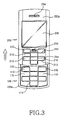
FIG. 3 is a plan view ofFIG 2 ; -
FIG. 4 is a left side view ofFIG. 2 ; and -
FIG. 5 is a partial perspective view showing a bottom surface of a portable terminal having a touch key according to a preferred embodiment of the present invention. - Hereinafter, preferred embodiments of the present invention will be described with reference to the accompanying drawings. In the following description of the present invention, a detailed description of known functions and configurations incorporated herein will be omitted when it may make the subject matter of the present invention unclear.
- As shown in
FIGs. 1 to 4 , a portable terminal according to the present invention includes a plurality of first andsecond touch keys first parts second parts second touch keys first touch keys 110 are aligned adjacent to each other along horizontal and vertical directions thereof In addition, thefirst touch keys 110 are integrally formed with each other, and thesecond touch keys 210 are also integrally formed with each other. - In detail, the portable terminal according to the present invention includes a
main housing 100, a slidinghousing 200 moving lengthwise along themain housing 100 while a lower surface of the slidinghousing 200 facing an upper surface of themain housing 100,first touch keys 110 aligned in a predetermined region of anupper surface 100a of themain housing 100, andfirst parts first touch keys 110. Above-mentionedtouch keys first parts first parts - The
first parts upper surface 100a of themain housing 100, and are continuously formed. In addition, thefirst touch keys 110 are integrally formed with thefirst parts - The sliding
housing 200 includes a plurality ofsecond touch keys 210, which are formed on an upper surface of the slidinghousing 200 in order to allow a user to input data through a touch action. In addition,second parts housing 200 in order to divide touch regions of thesecond touch keys 210. Thesecond parts upper surface 200a of thesliding housing 200. In addition, thesecond touch keys 210 and thesecond parts protrusions - Preferably, a
protuberance section 216 is formed at a predetermined portion adjacent to thesecond touch keys 210, that is, at an upper portion of the slidinghousing 200 to facilitate sliding movement of the slidinghousing 200. Theprotuberance section 216 includes a plurality of protuberances extending in a direction perpendicular to a sliding direction of thesliding housing 200. Theprotuberance section 216 is integrally formed with thesecond touch keys 210. - In addition, the sliding
housing 200 is provided on theupper surface 200a thereof with aspeaker 204, a liquidcrystal display device 206 disposed adjacently to thespeaker 204, and thesecond touch keys 210 disposed adjacently to the liquidcrystal display device 206. When the slidinghousing 200 is moved into an open position or a closed position with respect to themain housing 100, thefirst touch keys 110 are opened or closed according to the movement of the slidinghousing 200. Thesecond touch keys 210 remain exposed due to their external location. Accordingly, thefirst touch keys 110 are opened or closed depending on the sliding movement of the slidinghousing 200. - As shown in
FIG 1 , when the slidinghousing 200 is positioned in a closed position with respect to themain housing 100, thesecond touch keys 210 overlap thefirst touch keys 110. As shown inFIG 2 , when the slidinghousing 200 is moved into the open position away from themain housing 100, thefirst touch keys 110 are disposed adjacently to thesecond touch keys 210. - As shown in
FIG 5 , the portable terminal according to the present invention is provided on a lower surface thereof with acamera lens 121 and a pair ofillumination units 122 disposed adjacently to thecamera lens 121. In addition, thecamera lens 121 and theillumination units 122 are protected by a slidingcover 120. - As described above, according to the present invention, first and second touch keys are employed in the portable terminal, so an external appearance of the portable terminal becomes simple and cosmetically appealing. In addition, a user can input data by a simple touch action, so a data input action can be conveniently achieved. In addition, a touch error can be prevented by employing protrusions for dividing touch regions. In addition, the protuberance section according to the present invention is provided on a predetermined region of the sliding housing, so the sliding movement of the sliding housing can be easily performed.
- While the invention has been shown and described with reference to certain preferred embodiments thereof, it will be understood by those skilled in the art that various changes in form and details may be made therein without departing from the scope of the invention as defined by the appended claims.
Claims (17)
- A portable terminal comprising:- a main housing (100);- a cover housing (200), which is opened and closed with respect to the main housing (100) and- a plurality of first touch keys (110) aligned on an upper surface (100a) of the main housing (100) to allow a user to input data into the portable terminal with a touch action, characterized by- first protrusions (112, 114) for dividing touch regions of the first touch keys (110).
- The portable terminal according to claim 1, characterized in that said cover housing (200) is a sliding housing.
- The portable terminal according to claim 1 or 2, characterized in that the first protrusions (112) divide the touch area horizontally.
- The portable terminal according to one of the previous claims, characterized by second protrusions (114) dividing the touch area vertically.
- The portable terminal according to claim 1 or 2, characterized in that the protrusions (112, 114) shape the touch area into a circle.
- The portable terminal according to claim 1 or 2, characterized in that the protrusions (112, 114) shape the touch area into a symbol.
- The portable terminal according to one of the previous claims, characterized in that a plurality of second touch keys (210) are provided on an upper surface (200a) of the sliding housing (200) to allow a user to input data by touching the second touch keys (210).
- The portable terminal according to claim 7, characterized in that touch regions of the second touch keys (210) are divided by second parts (212, 214).
- The portable terminal according to claim 7 or 8, characterized in that the second parts (212, 214) are protrusions protruding from the upper surface (200a) of the sliding housing (200).
- The portable terminal according to one of the previous claims, characterized in that the first and second protrusions and/or second parts (112, 114; 212, 214) vertically protrude from the upper surfaces (100a, 200a) of the main housing (100) or the sliding housing (200), respectively.
- The portable terminal according to one of the previous claims, characterized in that a protuberance section (216) is integrally formed with the second touch keys (210) for slidably opening and closing the sliding housing (200).
- The portable terminal according to one of the previous claims, characterized in that the first and second protrusions (112, 114) and/or the second parts (212, 214) are continuously formed.
- The portable terminal according to one of the previous claims, characterized in that the first touch keys (110) are opened and closed by the sliding housing (200), the second touch keys (210) overlap the first touch keys (110) when the sliding housing is positioned in a closed position with respect to the main housing (100), and the first touch keys (110) are disposed adjacently to the second touch keys (210) when the sliding housing is moved into an open position away from the main housing.
- The portable terminal according to one of the previous claims, characterized in that the first touch keys (110) and/or the second touch keys (210) are integrally formed with the first and second protrusions and second parts (112, 114; 212, 214), respectively.
- The portable terminal according to one of the previous claims, characterized in that a camera lens (121) is embedded on a bottom surface of the main housing (100) for taking photographs and movies.
- The portable terminal according to claim 15, characterized in that at least one illumination unit (122) is disposed adjacent to the camera lens (121).
- The portable terminal according to claim 15 or 16, characterized in that a sliding cover (120) is arranged for protecting the camera lens (121) and at least one illumination unit (122) when not in use.
Applications Claiming Priority (2)
| Application Number | Priority Date | Filing Date | Title |
|---|---|---|---|
| KR1020040025721A KR100640388B1 (en) | 2004-04-14 | 2004-04-14 | Portable telephone with touch key |
| KR2004025721 | 2004-04-14 |
Publications (3)
| Publication Number | Publication Date |
|---|---|
| EP1587284A2 EP1587284A2 (en) | 2005-10-19 |
| EP1587284A3 EP1587284A3 (en) | 2007-03-14 |
| EP1587284B1 true EP1587284B1 (en) | 2010-07-28 |
Family
ID=34934864
Family Applications (1)
| Application Number | Title | Priority Date | Filing Date |
|---|---|---|---|
| EP05007654A Expired - Fee Related EP1587284B1 (en) | 2004-04-14 | 2005-04-07 | Portable terminal with touch key |
Country Status (5)
| Country | Link |
|---|---|
| US (1) | US20050233708A1 (en) |
| EP (1) | EP1587284B1 (en) |
| KR (1) | KR100640388B1 (en) |
| CN (1) | CN100493104C (en) |
| DE (1) | DE602005022516D1 (en) |
Families Citing this family (9)
| Publication number | Priority date | Publication date | Assignee | Title |
|---|---|---|---|---|
| US7070349B2 (en) * | 2004-06-18 | 2006-07-04 | Motorola, Inc. | Thin keyboard and components for electronics devices and methods |
| KR100747246B1 (en) * | 2005-12-30 | 2007-08-07 | 엘지전자 주식회사 | Mobile communication terminal with touch-pad integrated printed circuit board |
| JP4151849B2 (en) * | 2006-04-20 | 2008-09-17 | ポリマテック株式会社 | Key sheet |
| KR100827228B1 (en) * | 2006-05-01 | 2008-05-07 | 삼성전자주식회사 | Apparatus and method for providing area separate means with touch function |
| CN201336027Y (en) * | 2008-11-28 | 2009-10-28 | 鸿富锦精密工业(深圳)有限公司 | Electronic device |
| GB2485534B (en) * | 2010-11-15 | 2016-08-17 | Edesix Ltd | Imaging recording apparatus |
| KR101220459B1 (en) * | 2010-12-27 | 2013-01-10 | 이승진 | Multi-Accesory for Portable PC |
| CN102520822B (en) * | 2011-12-09 | 2014-09-10 | 无锡知谷网络科技有限公司 | Touch-recognizable touch screen for mobile phone for the visually impaired and response manner thereof |
| USD743925S1 (en) * | 2013-12-12 | 2015-11-24 | Samsung Electronics Co., Ltd. | Telephone |
Family Cites Families (13)
| Publication number | Priority date | Publication date | Assignee | Title |
|---|---|---|---|---|
| GB2359963B (en) * | 1999-10-15 | 2004-02-11 | Matsushita Electric Ind Co Ltd | Portable telephone apparatus and control method thereof |
| US6952597B2 (en) * | 2001-01-22 | 2005-10-04 | Wildseed Ltd. | Wireless mobile phone with key stroking based input facilities |
| JP2002287889A (en) * | 2001-03-23 | 2002-10-04 | Sharp Corp | Pen input device |
| EP1298888A1 (en) * | 2001-09-28 | 2003-04-02 | Telefonaktiebolaget L M Ericsson (Publ) | A portable communication terminal |
| JP2003143286A (en) * | 2001-10-31 | 2003-05-16 | Nec Corp | Portable telephone set |
| US6947545B2 (en) * | 2002-07-30 | 2005-09-20 | John Elias Adams | Number keypad corral |
| JP2004187273A (en) * | 2002-11-22 | 2004-07-02 | Casio Comput Co Ltd | Portable telephone terminal, and calling history display method |
| US7406331B2 (en) * | 2003-06-17 | 2008-07-29 | Sony Ericsson Mobile Communications Ab | Use of multi-function switches for camera zoom functionality on a mobile phone |
| KR100536939B1 (en) * | 2003-07-11 | 2005-12-19 | 엘지전자 주식회사 | Slide type portable terminal |
| US7283852B2 (en) * | 2003-09-10 | 2007-10-16 | Nokia Corporation | Movable functional elements for mobile communication device |
| US20050070348A1 (en) * | 2003-09-29 | 2005-03-31 | Inventec Appliances Corp. | Hand-held communication electronic apparatus having two slidable keypads |
| KR20050048758A (en) * | 2003-11-20 | 2005-05-25 | 지현진 | Inputting method and appartus of character using virtual button on touch screen or touch pad |
| US20050164752A1 (en) * | 2004-01-23 | 2005-07-28 | Stephen Lau | Palm-size foldable computing and communication assembly for personal users |
-
2004
- 2004-04-14 KR KR1020040025721A patent/KR100640388B1/en not_active IP Right Cessation
- 2004-12-23 US US11/020,840 patent/US20050233708A1/en not_active Abandoned
-
2005
- 2005-04-07 EP EP05007654A patent/EP1587284B1/en not_active Expired - Fee Related
- 2005-04-07 DE DE602005022516T patent/DE602005022516D1/en active Active
- 2005-04-13 CN CNB2005100649821A patent/CN100493104C/en not_active Expired - Fee Related
Also Published As
| Publication number | Publication date |
|---|---|
| CN1684476A (en) | 2005-10-19 |
| US20050233708A1 (en) | 2005-10-20 |
| DE602005022516D1 (en) | 2010-09-09 |
| EP1587284A3 (en) | 2007-03-14 |
| EP1587284A2 (en) | 2005-10-19 |
| CN100493104C (en) | 2009-05-27 |
| KR100640388B1 (en) | 2006-10-30 |
| KR20050100479A (en) | 2005-10-19 |
Similar Documents
| Publication | Publication Date | Title |
|---|---|---|
| EP1587284B1 (en) | Portable terminal with touch key | |
| US7395100B2 (en) | Portable communication apparatus having keys moved up/down by rotation | |
| KR100842516B1 (en) | Mobile phone | |
| EP1720326B1 (en) | Portable terminal with two bodies being both foldable and slidable relative to each other | |
| US7532916B2 (en) | Slide-type portable terminal using flexible material | |
| EP1804468B1 (en) | Mobile communication terminal having two keypads | |
| EP1499094B1 (en) | Bi-directional sliding-type portable terminal comprising a camera | |
| EP1635541B1 (en) | Data input key for a portable apparatus and key array thereof | |
| KR100735304B1 (en) | Sliding device for mobile phone | |
| US20050020323A1 (en) | Portable digital communication device | |
| EP1806909B1 (en) | Portable communication terminal for games and user interfacing device thereof | |
| KR100630102B1 (en) | Portable communication device with sliding pop up type keypad | |
| KR20040021366A (en) | Portable information phone with expansion data inputting unit | |
| EP1748628B1 (en) | Slim portable terminal | |
| EP1528758B1 (en) | Synchronized sliding module for a splitted keyboard of a mobile terminal and a method of using it. | |
| WO2004062125A1 (en) | Self operating opening mechanism for use in a hand-held electronic device | |
| KR100640342B1 (en) | Swing-type portable digital communication device with step-compensated mechanism | |
| CN100525328C (en) | Portable terminal with slide keypad for convenient data input | |
| KR100469855B1 (en) | Portable communication device | |
| KR100532272B1 (en) | Sliding type portable digital communication device | |
| KR20060121483A (en) | Sliding-type mobile phone | |
| KR20050095418A (en) | Portable communication device | |
| KR100819241B1 (en) | Keypad for mobile phone | |
| KR20070007546A (en) | Mobile phone with sub-unit for touch-inputting | |
| KR20070020913A (en) | Mobile phone with specific function using visual operating |
Legal Events
| Date | Code | Title | Description |
|---|---|---|---|
| PUAI | Public reference made under article 153(3) epc to a published international application that has entered the european phase |
Free format text: ORIGINAL CODE: 0009012 |
|
| 17P | Request for examination filed |
Effective date: 20050407 |
|
| AK | Designated contracting states |
Kind code of ref document: A2 Designated state(s): AT BE BG CH CY CZ DE DK EE ES FI FR GB GR HU IE IS IT LI LT LU MC NL PL PT RO SE SI SK TR |
|
| AX | Request for extension of the european patent |
Extension state: AL BA HR LV MK YU |
|
| PUAL | Search report despatched |
Free format text: ORIGINAL CODE: 0009013 |
|
| AK | Designated contracting states |
Kind code of ref document: A3 Designated state(s): AT BE BG CH CY CZ DE DK EE ES FI FR GB GR HU IE IS IT LI LT LU MC NL PL PT RO SE SI SK TR |
|
| AX | Request for extension of the european patent |
Extension state: AL BA HR LV MK YU |
|
| AKX | Designation fees paid |
Designated state(s): DE FR GB |
|
| 17Q | First examination report despatched |
Effective date: 20090904 |
|
| GRAP | Despatch of communication of intention to grant a patent |
Free format text: ORIGINAL CODE: EPIDOSNIGR1 |
|
| GRAS | Grant fee paid |
Free format text: ORIGINAL CODE: EPIDOSNIGR3 |
|
| GRAA | (expected) grant |
Free format text: ORIGINAL CODE: 0009210 |
|
| AK | Designated contracting states |
Kind code of ref document: B1 Designated state(s): DE FR GB |
|
| REG | Reference to a national code |
Ref country code: GB Ref legal event code: FG4D |
|
| REF | Corresponds to: |
Ref document number: 602005022516 Country of ref document: DE Date of ref document: 20100909 Kind code of ref document: P |
|
| PLBE | No opposition filed within time limit |
Free format text: ORIGINAL CODE: 0009261 |
|
| STAA | Information on the status of an ep patent application or granted ep patent |
Free format text: STATUS: NO OPPOSITION FILED WITHIN TIME LIMIT |
|
| 26N | No opposition filed |
Effective date: 20110429 |
|
| REG | Reference to a national code |
Ref country code: DE Ref legal event code: R097 Ref document number: 602005022516 Country of ref document: DE Effective date: 20110429 |
|
| REG | Reference to a national code |
Ref country code: FR Ref legal event code: PLFP Year of fee payment: 12 |
|
| REG | Reference to a national code |
Ref country code: FR Ref legal event code: PLFP Year of fee payment: 13 |
|
| REG | Reference to a national code |
Ref country code: FR Ref legal event code: PLFP Year of fee payment: 14 |
|
| PGFP | Annual fee paid to national office [announced via postgrant information from national office to epo] |
Ref country code: GB Payment date: 20180321 Year of fee payment: 14 |
|
| PGFP | Annual fee paid to national office [announced via postgrant information from national office to epo] |
Ref country code: FR Payment date: 20180322 Year of fee payment: 14 |
|
| PGFP | Annual fee paid to national office [announced via postgrant information from national office to epo] |
Ref country code: DE Payment date: 20180320 Year of fee payment: 14 |
|
| REG | Reference to a national code |
Ref country code: DE Ref legal event code: R119 Ref document number: 602005022516 Country of ref document: DE |
|
| GBPC | Gb: european patent ceased through non-payment of renewal fee |
Effective date: 20190407 |
|
| PG25 | Lapsed in a contracting state [announced via postgrant information from national office to epo] |
Ref country code: DE Free format text: LAPSE BECAUSE OF NON-PAYMENT OF DUE FEES Effective date: 20191101 Ref country code: GB Free format text: LAPSE BECAUSE OF NON-PAYMENT OF DUE FEES Effective date: 20190407 |
|
| PG25 | Lapsed in a contracting state [announced via postgrant information from national office to epo] |
Ref country code: FR Free format text: LAPSE BECAUSE OF NON-PAYMENT OF DUE FEES Effective date: 20190430 |