EP1587209A2 - Hydraulikaggregat für einen Kraftschrauber - Google Patents
Hydraulikaggregat für einen Kraftschrauber Download PDFInfo
- Publication number
- EP1587209A2 EP1587209A2 EP05007830A EP05007830A EP1587209A2 EP 1587209 A2 EP1587209 A2 EP 1587209A2 EP 05007830 A EP05007830 A EP 05007830A EP 05007830 A EP05007830 A EP 05007830A EP 1587209 A2 EP1587209 A2 EP 1587209A2
- Authority
- EP
- European Patent Office
- Prior art keywords
- housing
- motor
- hydraulic unit
- load
- unit according
- Prior art date
- Legal status (The legal status is an assumption and is not a legal conclusion. Google has not performed a legal analysis and makes no representation as to the accuracy of the status listed.)
- Granted
Links
Images

Classifications
-
- F—MECHANICAL ENGINEERING; LIGHTING; HEATING; WEAPONS; BLASTING
- F04—POSITIVE - DISPLACEMENT MACHINES FOR LIQUIDS; PUMPS FOR LIQUIDS OR ELASTIC FLUIDS
- F04B—POSITIVE-DISPLACEMENT MACHINES FOR LIQUIDS; PUMPS
- F04B23/00—Pumping installations or systems
- F04B23/02—Pumping installations or systems having reservoirs
- F04B23/021—Pumping installations or systems having reservoirs the pump being immersed in the reservoir
-
- F—MECHANICAL ENGINEERING; LIGHTING; HEATING; WEAPONS; BLASTING
- F04—POSITIVE - DISPLACEMENT MACHINES FOR LIQUIDS; PUMPS FOR LIQUIDS OR ELASTIC FLUIDS
- F04B—POSITIVE-DISPLACEMENT MACHINES FOR LIQUIDS; PUMPS
- F04B23/00—Pumping installations or systems
- F04B23/02—Pumping installations or systems having reservoirs
- F04B23/025—Pumping installations or systems having reservoirs the pump being located directly adjacent the reservoir
-
- H—ELECTRICITY
- H02—GENERATION; CONVERSION OR DISTRIBUTION OF ELECTRIC POWER
- H02K—DYNAMO-ELECTRIC MACHINES
- H02K9/00—Arrangements for cooling or ventilating
- H02K9/19—Arrangements for cooling or ventilating for machines with closed casing and closed-circuit cooling using a liquid cooling medium, e.g. oil
-
- H—ELECTRICITY
- H02—GENERATION; CONVERSION OR DISTRIBUTION OF ELECTRIC POWER
- H02P—CONTROL OR REGULATION OF ELECTRIC MOTORS, ELECTRIC GENERATORS OR DYNAMO-ELECTRIC CONVERTERS; CONTROLLING TRANSFORMERS, REACTORS OR CHOKE COILS
- H02P6/00—Arrangements for controlling synchronous motors or other dynamo-electric motors using electronic commutation dependent on the rotor position; Electronic commutators therefor
Definitions
- the invention relates to a hydraulic unit for supplying oil to a hydraulic load generating power screwdriver, containing an oil Reservoir, a pump and a pump driving electric motor, the a housing, which at the same time at least a part of the reservoir forms, wherein the rotor of the engine is surrounded by oil.
- a hydraulic unit for a power screwdriver has as a pressure generator Pump on, the oil from a reservoir sucks and feeds a consumer. From the consumer, a return line leads back to the reservoir.
- Hydraulic power units are known which contain the motor as submersible, which is arranged in the reservoir and immersed in the hydraulic fluid is.
- the heat generated in the engine by the hydraulic oil of the Engine dissipated. Because of the nested different housing Such an aggregate has a high weight and a considerable space requirement.
- the size of the motor and thus of the entire housing depends on the maximum load of a consumer powered by the hydraulic power unit shall be. If the consumer has a high hydraulic resistance, so is a correspondingly powerful motor in the hydraulic power unit is required.
- the invention is based on the object, a hydraulic unit for a To create power wrenches, which is relatively lightweight and little space However, it is able to cope with high peak loads.
- the hydraulic unit according to the present invention is defined by claim 1 Are defined.
- the motor is operated at a variable operating frequency Synchronous motor, and it is provided a motor control, in which the Operating frequency as a function of the load generated by the consumer so changes that with increasing load, the operating frequency is smaller.
- the motor control contains a frequency converter, which the Operating frequency for the motor supplies.
- the reduced Operating frequency linear with an increase of the load or one of the load dependent measured value.
- a pressure sensor may be provided which the Output pressure of the hydraulic unit measures.
- the outlet pressure is dependent from the load of the connected consumer.
- the consumer sets the Hydraulic oil is a great resistance to engine speed reduced.
- Another load-dependent size used for motor control can, is the current consumption of the motor.
- a corresponding Current sensor to be provided on the hydraulic unit.
- In the engine control can be a curve, table or other functional Dependent on the dependency of the course of the engine speed indicates the load-dependent measured value. According to this reading is the engine speed is set automatically.
- the housing Spacer for positioning the motor winding with radial distance to the Housing provided such that between the motor winding and the Housing is formed belonging to the reservoir free space.
- the Motor housing which also forms the housing of the hydraulic unit, is for the motor consisting of stator and rotor too large, so that between housing and stator winding a gap exists. This forms part of the Reservoir volume.
- the space is bridged by the spacers, which position the stator winding. So it's just a single case present, which also forms the motor housing and the reservoir housing.
- Rotor and stator of the engine are lapped directly by the hydraulic oil. As a result, the heat is better dissipated by the synchronous motor and the Motor is operated with higher power.
- the space between the stator and Housing forms a substantial part of the reservoir volume.
- the housing indicates on its outside ribs which extend in the axial direction of the engine; at one end of the housing is provided with a fan, which has a cooling air flow generated parallel to the ribs.
- the fan can sit directly on the motor shaft or driven by a gear of the motor shaft. In this case, the Cooling proportional to the speed of the motor.
- the motor winding of bordered by a hoop which is supported by the spacers on the housing is.
- the frost then forms a stator, the motor winding the required Gives stability.
- the pump of the hydraulic unit is a positive displacement pump or volumetric pump.
- gear pumps or Multi-piston pumps For this purpose, for example, gear pumps or Multi-piston pumps. These provide a flow of hydraulic oil, which the operating frequency of the motor is proportional.
- the hydraulic unit according to the invention is particularly suitable for Einpumpentechnik, in which only a single controlled pump unit the entire area in which the volume flow is changed, covering and also covers the entire pressure range, which depends on the load resistance.
- the hydraulic unit is suitable for the operation of Power wrenches and similar hydraulic consumers with strong fluctuating load resistance.
- the hydraulic unit has according to Figure 1, a housing 10, in which it is is a conventional motor housing of an electric motor.
- the housing 10 has a cylindrical inner wall 11 and has numerous longitudinally on its outside extending ribs 12 which form cooling fins.
- the housing 10 forms a profile body of an extruded profile. It is at one point of its circumference provided with an integrally formed longitudinal mounting plate 13 and on the diametrically opposite side is a mounting profile 14th for attaching components to the housing.
- the housing 10 contains the electric motor 15. This consists of a stator 16 and a rotor 17.
- the motor is a permanent magnet-energized Synchronous motor, the stator of a rotating field-generating stator winding 18th having.
- the rotor 17 consists of the motor shaft 19 and attached thereto Permanent magnet 20.
- the motor shaft 19 is in bearings 21, 22 in the (not shown) end walls of the housing 10 stored.
- the stator winding 18 is enclosed with a hoop 25, which has a closed Ring forms and surrounds the coil winding.
- a hoop 25 which has a closed Ring forms and surrounds the coil winding.
- spacers 26 are fixed, which radially inwardly stand out and keep the hoop 25 centered in the housing. In this way, the Stator 16 centered in the housing.
- the spacers 26 are strips that are in Longitudinal direction of the housing. At least there are three such bars provided, in the present embodiment, however, 4.
- the Spacers 26 are shorter than the axial length of the space 27 so that they Do not obstruct circulation of the hydraulic oil in the space 27.
- the spacer 26 By the spacer 26 is achieved that between the stator 16 and the Inner surface 11 of the housing, the annular space 27 is present, the Major part of the volume of a reservoir 28 forms.
- the reservoir is through the Housing 10 limited.
- the stator 16 and the rotor 17 are immersed in the hydraulic fluid.
- the motor shaft 19 has an eccentric ring 29 which has a (not shown) Pump drives.
- the suction inlet of the pump is via a hydraulic line with connected to the reservoir 28.
- the pump is a multi-piston pump a plurality of individual pumps, the star shape around the motor shaft 19 around are arranged, and the piston of the eccentric ring 29 which eccentrically with the motor shaft is firmly connected, are driven.
- Each of the individual pumps draws oil from the reservoir via a check valve and conveys it via a another check valve to the pump outlet.
- the multi-piston pump is a volumetric pump.
- a Fan 30 having a housing 31 which radially over the housing 10th survives.
- a fan which has an air flow 32nd generated along the ribs 12.
- the fan is connected to the motor shaft 19 connected and is driven by this. Because of the effective Heat dissipation results in good cooling. Due to the low warming of the Hydraulic unit also increases the efficiency. Because of the waiver a separate motor housing is the hydraulic unit of compact design and of low weight.
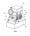
- FIG 2 the entire hydraulic unit is shown. You can see that Housing 10 with the longitudinal ribs 12. At one end is located the fan 30, which carries a flow of air along the outside of the housing drives. At the opposite end of the housing is the Pump part 40 with the pressure port 41 and the return port 42 at the Front side. Further, there is a manometer 43 attached, which the pressure displays.
- auxiliary reservoir 47 On an auxiliary reservoir 47 is located in a housing, the engine control 50. This is with (not shown) electrical lines with the Electric motor 15 connected.
- the pressure at the pressure port 41 is indicated by a (not shown) Pressure sensor determined. This pressure is a measure of the load of the connected Consumer. Depending on the pressure value, the engine control system controls 50, the electric motor 15 in such a way that at higher pressure, the speed of the Motors is reduced. As soon as the pressure decreases, it increases again the engine speed. In this way it is achieved that the engine Recorded performance essentially remains constant and broad regardless of the load status of the consumer.
Landscapes
- Engineering & Computer Science (AREA)
- Power Engineering (AREA)
- Mechanical Engineering (AREA)
- General Engineering & Computer Science (AREA)
- Motor Or Generator Cooling System (AREA)
- Supply Devices, Intensifiers, Converters, And Telemotors (AREA)
- Details Of Reciprocating Pumps (AREA)
- Fluid-Pressure Circuits (AREA)
- Auxiliary Drives, Propulsion Controls, And Safety Devices (AREA)
Abstract
Description
- Figur 1
- eine schematische perspektivische Darstellung eines Ausführungsbeispiels des Hydraulikaggregats in aufgeschnittenem Zustand, und
- Figur 2
- eine perspektivische Gesamtansicht des Hydraulikaggregates.
Claims (9)
- Hydraulikaggregat zur Lieferung von Öl an einen eine hydraulische Last erzeugenden Kraftschrauber, mit einem Öl enthaltenden Reservoir (28), einer Pumpe und einem die Pumpe treibenden elektrischen Motor (15), der ein Gehäuse (10) aufweist, welches zugleich mindestens einen Teil des Reservoirs (28) bildet, wobei der Motor (15) von Öl umspült ist,
dadurch gekennzeichnet, dass der Motor (15) ein mit variabler Betriebsfrequenz betriebener Synchronmotor ist, und dass eine Motorsteuerung (50) vorgesehen ist, die die Betriebsfrequenz in Abhängigkeit von der vom Verbraucher erzeugten Last derart verändert, dass mit zunehmender Last die Betriebsfrequenz kleiner wird. - Hydraulikaggregat nach Anspruch 1, dadurch gekennzeichnet, dass die Regelung des Motors derart erfolgt, dass die von dem Motor (15) erzeugte Leistung unabhängig von der Größe der Last im Wesentlichen konstant ist.
- Hydraulikaggregat nach Anspruch 1 oder 2, dadurch gekennzeichnet, dass zur Ermittlung der Last ein Drucksensor vorgesehen ist, der den Ausgangsdruck des Hydraulikaggregates misst.
- Hydraulikaggregat nach Anspruch 1 oder 2, dadurch gekennzeichnet, dass zur Ermittlung der Last ein Stromsensor vorgesehen ist, der die Stromaufnahme des Motors (15) misst.
- Hydraulikaggregat nach einem der Ansprüche 1 bis 4, dadurch gekennzeichnet, dass in dem Gehäuse (10) Abstandhalter (26) zur Positionierung der Statorwicklung (18) des Motors mit radialem Abstand zu dem Gehäuse (10) vorgesehen sind, derart, dass zwischen Statorwicklung (18) und Gehäuse (10) ein zu dem Reservoir (28) gehörender Raum (27) gebildet ist.
- Hydraulikaggregat nach Anspruch 5, dadurch gekennzeichnet, dass die Statorwicklung (18) von einem Reif (25) eingefasst ist, welcher durch die Abstandhalter (26) am Gehäuse (10) abgestützt ist.
- Hydraulikaggregat nach Anspruch 5, dadurch gekennzeichnet, dass der Raum (27) sich über die gesamte Länge des Gehäuses (10) erstreckt.
- Hydraulikaggregat nach einem der Ansprüche 1 bis 7, dadurch gekennzeichnet, dass das Gehäuse (10) an seiner Außenseite Rippen (12) aufweist, die in Achsrichtung des Motors (15) verlaufen, und dass an einem Ende des Gehäuses ein Lüfter (30) vorgesehen ist, der radial über das Gehäuse vorsteht und einen Kühlluftstrom (32) entlang der Rippen (12) erzeugt.
- Hydraulikaggregat nach einem der Ansprüche 1 bis 8, dadurch gekennzeichnet, dass das Gehäuse (10) an seiner Unterseite eine angeformte von Rippen (12) freie Montageplatte (13) aufweist und an seiner Oberseite ein Befestigungsprofil (14) für die Motorsteuerung.
Priority Applications (1)
| Application Number | Priority Date | Filing Date | Title |
|---|---|---|---|
| PL05007830T PL1587209T3 (pl) | 2004-04-17 | 2005-04-09 | Agregat hydrauliczny dla wkrętarki |
Applications Claiming Priority (2)
| Application Number | Priority Date | Filing Date | Title |
|---|---|---|---|
| DE202004006109U | 2004-04-17 | ||
| DE202004006109U DE202004006109U1 (de) | 2004-04-17 | 2004-04-17 | Hydraulikaggregat |
Publications (3)
| Publication Number | Publication Date |
|---|---|
| EP1587209A2 true EP1587209A2 (de) | 2005-10-19 |
| EP1587209A3 EP1587209A3 (de) | 2007-05-09 |
| EP1587209B1 EP1587209B1 (de) | 2012-12-05 |
Family
ID=32520767
Family Applications (2)
| Application Number | Title | Priority Date | Filing Date |
|---|---|---|---|
| EP05007829A Withdrawn EP1587206A3 (de) | 2004-04-17 | 2005-04-09 | Hydraulikaggregat |
| EP05007830A Expired - Lifetime EP1587209B1 (de) | 2004-04-17 | 2005-04-09 | Hydraulikaggregat für einen Kraftschrauber |
Family Applications Before (1)
| Application Number | Title | Priority Date | Filing Date |
|---|---|---|---|
| EP05007829A Withdrawn EP1587206A3 (de) | 2004-04-17 | 2005-04-09 | Hydraulikaggregat |
Country Status (5)
| Country | Link |
|---|---|
| EP (2) | EP1587206A3 (de) |
| DE (1) | DE202004006109U1 (de) |
| DK (1) | DK1587209T3 (de) |
| ES (1) | ES2400909T3 (de) |
| PL (1) | PL1587209T3 (de) |
Families Citing this family (1)
| Publication number | Priority date | Publication date | Assignee | Title |
|---|---|---|---|---|
| DE202005005165U1 (de) † | 2005-04-01 | 2006-08-17 | Wagner, Paul-Heinz | Hydraulikaggregat |
Citations (2)
| Publication number | Priority date | Publication date | Assignee | Title |
|---|---|---|---|---|
| EP0509724A1 (de) | 1991-04-18 | 1992-10-21 | Vickers Incorporated | Kraftübertragung |
| US20030206805A1 (en) | 2000-04-14 | 2003-11-06 | Bishop Michael B. | Variable speed hydraulic pump |
Family Cites Families (2)
| Publication number | Priority date | Publication date | Assignee | Title |
|---|---|---|---|---|
| DE3513472C2 (de) * | 1985-04-15 | 1995-04-27 | Heilmeier & Weinlein | Hydraulisches Motor-Pumpen-Aggregat |
| DE19920563A1 (de) * | 1999-05-05 | 2000-11-09 | Mannesmann Rexroth Ag | Kompaktes Hydraulikaggregat |
-
2004
- 2004-04-17 DE DE202004006109U patent/DE202004006109U1/de not_active Expired - Lifetime
-
2005
- 2005-04-09 ES ES05007830T patent/ES2400909T3/es not_active Expired - Lifetime
- 2005-04-09 PL PL05007830T patent/PL1587209T3/pl unknown
- 2005-04-09 EP EP05007829A patent/EP1587206A3/de not_active Withdrawn
- 2005-04-09 EP EP05007830A patent/EP1587209B1/de not_active Expired - Lifetime
- 2005-04-09 DK DK05007830.2T patent/DK1587209T3/da active
Patent Citations (2)
| Publication number | Priority date | Publication date | Assignee | Title |
|---|---|---|---|---|
| EP0509724A1 (de) | 1991-04-18 | 1992-10-21 | Vickers Incorporated | Kraftübertragung |
| US20030206805A1 (en) | 2000-04-14 | 2003-11-06 | Bishop Michael B. | Variable speed hydraulic pump |
Also Published As
| Publication number | Publication date |
|---|---|
| PL1587209T3 (pl) | 2013-04-30 |
| EP1587209A3 (de) | 2007-05-09 |
| EP1587206A3 (de) | 2007-08-08 |
| DE202004006109U1 (de) | 2004-06-17 |
| EP1587206A2 (de) | 2005-10-19 |
| ES2400909T3 (es) | 2013-04-15 |
| EP1587209B1 (de) | 2012-12-05 |
| DK1587209T3 (da) | 2013-02-11 |
Similar Documents
| Publication | Publication Date | Title |
|---|---|---|
| DE3820003C2 (de) | ||
| EP1999375B1 (de) | Verdichtereinheit | |
| DE102004007882B4 (de) | Luftkompressor und Verfahren zu seinem Steuern | |
| DE102011012586B4 (de) | Gerotorpumpe mit Außenringantrieb | |
| EP3374642B1 (de) | Elektrische kfz-axial-flüssigkeitspumpe | |
| WO2000068572A1 (de) | Kompaktes hydraulikaggregat | |
| DE102016010669A1 (de) | Motor-Pumpenvorrichtung | |
| EP2185819A1 (de) | Kältemittelkompressor | |
| WO2015091587A1 (de) | Kompressor | |
| EP1045143B1 (de) | Elektrohydraulisches Motorpumpenaggregat | |
| EP2385252B2 (de) | Hydraulikaggregat | |
| EP2025934B1 (de) | Motorpumpenaggregat | |
| EP1587209B1 (de) | Hydraulikaggregat für einen Kraftschrauber | |
| EP1495227A2 (de) | Hydraulisches pumpenaggregat | |
| DE69419864T2 (de) | Fluidmaschine mit Induktionsmotor | |
| EP2022990B1 (de) | Werkzeugmaschine und Versorgungsaggregat | |
| DE10112500A1 (de) | Elektrohydraulische Antriebseinheit | |
| EP1777411A1 (de) | Motor-Pumpen-Aggregat | |
| DE102007034225B4 (de) | Elektromotor für das Elektromotor-Pumpen-Aggregat eines Kraftfahrzeug-Antiblockiersystems | |
| DE2117838A1 (de) | Elektroverdichter mit geradliniger Bewegung | |
| EP0810717B1 (de) | Elektrohydraulisches Motorpumpenaggregat | |
| EP2157318A2 (de) | Hydraulikversorgungseinheit | |
| WO2015185179A1 (de) | Elektrisch betriebene motor-pumpeneinheit | |
| DE102022117052A1 (de) | Elektro-hydraulisches Antriebssystem | |
| DE102016112555B4 (de) | Kfz-Hilfsaggregat-Vakuumpumpe |
Legal Events
| Date | Code | Title | Description |
|---|---|---|---|
| PUAI | Public reference made under article 153(3) epc to a published international application that has entered the european phase |
Free format text: ORIGINAL CODE: 0009012 |
|
| AK | Designated contracting states |
Kind code of ref document: A2 Designated state(s): AT BE BG CH CY CZ DE DK EE ES FI FR GB GR HU IE IS IT LI LT LU MC NL PL PT RO SE SI SK TR |
|
| AX | Request for extension of the european patent |
Extension state: AL BA HR LV MK YU |
|
| PUAL | Search report despatched |
Free format text: ORIGINAL CODE: 0009013 |
|
| AK | Designated contracting states |
Kind code of ref document: A3 Designated state(s): AT BE BG CH CY CZ DE DK EE ES FI FR GB GR HU IE IS IT LI LT LU MC NL PL PT RO SE SI SK TR |
|
| AX | Request for extension of the european patent |
Extension state: AL BA HR LV MK YU |
|
| 17P | Request for examination filed |
Effective date: 20070706 |
|
| 17Q | First examination report despatched |
Effective date: 20070903 |
|
| AKX | Designation fees paid |
Designated state(s): AT BE BG CH CY CZ DE DK EE ES FI FR GB GR HU IE IS IT LI LT LU MC NL PL PT RO SE SI SK TR |
|
| RAP1 | Party data changed (applicant data changed or rights of an application transferred) |
Owner name: WAGNER VERMOEGENSVERWALTUNGS-GMBH & CO. KG |
|
| GRAP | Despatch of communication of intention to grant a patent |
Free format text: ORIGINAL CODE: EPIDOSNIGR1 |
|
| GRAS | Grant fee paid |
Free format text: ORIGINAL CODE: EPIDOSNIGR3 |
|
| GRAA | (expected) grant |
Free format text: ORIGINAL CODE: 0009210 |
|
| AK | Designated contracting states |
Kind code of ref document: B1 Designated state(s): AT BE BG CH CY CZ DE DK EE ES FI FR GB GR HU IE IS IT LI LT LU MC NL PL PT RO SE SI SK TR |
|
| REG | Reference to a national code |
Ref country code: GB Ref legal event code: FG4D Free format text: NOT ENGLISH |
|
| REG | Reference to a national code |
Ref country code: CH Ref legal event code: EP |
|
| REG | Reference to a national code |
Ref country code: AT Ref legal event code: REF Ref document number: 587734 Country of ref document: AT Kind code of ref document: T Effective date: 20121215 |
|
| REG | Reference to a national code |
Ref country code: IE Ref legal event code: FG4D Free format text: LANGUAGE OF EP DOCUMENT: GERMAN |
|
| REG | Reference to a national code |
Ref country code: DE Ref legal event code: R096 Ref document number: 502005013310 Country of ref document: DE Effective date: 20130131 |
|
| REG | Reference to a national code |
Ref country code: DK Ref legal event code: T3 |
|
| REG | Reference to a national code |
Ref country code: ES Ref legal event code: FG2A Ref document number: 2400909 Country of ref document: ES Kind code of ref document: T3 Effective date: 20130415 |
|
| PG25 | Lapsed in a contracting state [announced via postgrant information from national office to epo] |
Ref country code: SE Free format text: LAPSE BECAUSE OF FAILURE TO SUBMIT A TRANSLATION OF THE DESCRIPTION OR TO PAY THE FEE WITHIN THE PRESCRIBED TIME-LIMIT Effective date: 20121205 Ref country code: FI Free format text: LAPSE BECAUSE OF FAILURE TO SUBMIT A TRANSLATION OF THE DESCRIPTION OR TO PAY THE FEE WITHIN THE PRESCRIBED TIME-LIMIT Effective date: 20121205 Ref country code: LT Free format text: LAPSE BECAUSE OF FAILURE TO SUBMIT A TRANSLATION OF THE DESCRIPTION OR TO PAY THE FEE WITHIN THE PRESCRIBED TIME-LIMIT Effective date: 20121205 |
|
| REG | Reference to a national code |
Ref country code: PL Ref legal event code: T3 |
|
| REG | Reference to a national code |
Ref country code: NL Ref legal event code: VDEP Effective date: 20121205 |
|
| REG | Reference to a national code |
Ref country code: LT Ref legal event code: MG4D |
|
| PG25 | Lapsed in a contracting state [announced via postgrant information from national office to epo] |
Ref country code: SI Free format text: LAPSE BECAUSE OF FAILURE TO SUBMIT A TRANSLATION OF THE DESCRIPTION OR TO PAY THE FEE WITHIN THE PRESCRIBED TIME-LIMIT Effective date: 20121205 Ref country code: GR Free format text: LAPSE BECAUSE OF FAILURE TO SUBMIT A TRANSLATION OF THE DESCRIPTION OR TO PAY THE FEE WITHIN THE PRESCRIBED TIME-LIMIT Effective date: 20130306 Ref country code: CY Free format text: LAPSE BECAUSE OF FAILURE TO SUBMIT A TRANSLATION OF THE DESCRIPTION OR TO PAY THE FEE WITHIN THE PRESCRIBED TIME-LIMIT Effective date: 20121205 |
|
| PG25 | Lapsed in a contracting state [announced via postgrant information from national office to epo] |
Ref country code: SK Free format text: LAPSE BECAUSE OF FAILURE TO SUBMIT A TRANSLATION OF THE DESCRIPTION OR TO PAY THE FEE WITHIN THE PRESCRIBED TIME-LIMIT Effective date: 20121205 Ref country code: BG Free format text: LAPSE BECAUSE OF FAILURE TO SUBMIT A TRANSLATION OF THE DESCRIPTION OR TO PAY THE FEE WITHIN THE PRESCRIBED TIME-LIMIT Effective date: 20130305 Ref country code: IS Free format text: LAPSE BECAUSE OF FAILURE TO SUBMIT A TRANSLATION OF THE DESCRIPTION OR TO PAY THE FEE WITHIN THE PRESCRIBED TIME-LIMIT Effective date: 20130405 Ref country code: EE Free format text: LAPSE BECAUSE OF FAILURE TO SUBMIT A TRANSLATION OF THE DESCRIPTION OR TO PAY THE FEE WITHIN THE PRESCRIBED TIME-LIMIT Effective date: 20121205 Ref country code: CZ Free format text: LAPSE BECAUSE OF FAILURE TO SUBMIT A TRANSLATION OF THE DESCRIPTION OR TO PAY THE FEE WITHIN THE PRESCRIBED TIME-LIMIT Effective date: 20121205 |
|
| PG25 | Lapsed in a contracting state [announced via postgrant information from national office to epo] |
Ref country code: RO Free format text: LAPSE BECAUSE OF FAILURE TO SUBMIT A TRANSLATION OF THE DESCRIPTION OR TO PAY THE FEE WITHIN THE PRESCRIBED TIME-LIMIT Effective date: 20121205 Ref country code: PT Free format text: LAPSE BECAUSE OF FAILURE TO SUBMIT A TRANSLATION OF THE DESCRIPTION OR TO PAY THE FEE WITHIN THE PRESCRIBED TIME-LIMIT Effective date: 20130405 Ref country code: NL Free format text: LAPSE BECAUSE OF FAILURE TO SUBMIT A TRANSLATION OF THE DESCRIPTION OR TO PAY THE FEE WITHIN THE PRESCRIBED TIME-LIMIT Effective date: 20121205 |
|
| PLBE | No opposition filed within time limit |
Free format text: ORIGINAL CODE: 0009261 |
|
| STAA | Information on the status of an ep patent application or granted ep patent |
Free format text: STATUS: NO OPPOSITION FILED WITHIN TIME LIMIT |
|
| BERE | Be: lapsed |
Owner name: WAGNER VERMOGENSVERWALTUNGS-GMBH & CO. K.G. Effective date: 20130430 |
|
| 26N | No opposition filed |
Effective date: 20130906 |
|
| PG25 | Lapsed in a contracting state [announced via postgrant information from national office to epo] |
Ref country code: MC Free format text: LAPSE BECAUSE OF FAILURE TO SUBMIT A TRANSLATION OF THE DESCRIPTION OR TO PAY THE FEE WITHIN THE PRESCRIBED TIME-LIMIT Effective date: 20121205 |
|
| REG | Reference to a national code |
Ref country code: CH Ref legal event code: PL |
|
| REG | Reference to a national code |
Ref country code: DE Ref legal event code: R097 Ref document number: 502005013310 Country of ref document: DE Effective date: 20130906 |
|
| REG | Reference to a national code |
Ref country code: IE Ref legal event code: MM4A |
|
| PG25 | Lapsed in a contracting state [announced via postgrant information from national office to epo] |
Ref country code: CH Free format text: LAPSE BECAUSE OF NON-PAYMENT OF DUE FEES Effective date: 20130430 Ref country code: BE Free format text: LAPSE BECAUSE OF NON-PAYMENT OF DUE FEES Effective date: 20130430 Ref country code: LI Free format text: LAPSE BECAUSE OF NON-PAYMENT OF DUE FEES Effective date: 20130430 |
|
| PG25 | Lapsed in a contracting state [announced via postgrant information from national office to epo] |
Ref country code: IE Free format text: LAPSE BECAUSE OF NON-PAYMENT OF DUE FEES Effective date: 20130409 |
|
| REG | Reference to a national code |
Ref country code: AT Ref legal event code: MM01 Ref document number: 587734 Country of ref document: AT Kind code of ref document: T Effective date: 20130409 |
|
| PG25 | Lapsed in a contracting state [announced via postgrant information from national office to epo] |
Ref country code: AT Free format text: LAPSE BECAUSE OF NON-PAYMENT OF DUE FEES Effective date: 20130409 |
|
| REG | Reference to a national code |
Ref country code: FR Ref legal event code: PLFP Year of fee payment: 11 |
|
| PG25 | Lapsed in a contracting state [announced via postgrant information from national office to epo] |
Ref country code: LU Free format text: LAPSE BECAUSE OF NON-PAYMENT OF DUE FEES Effective date: 20130409 Ref country code: HU Free format text: LAPSE BECAUSE OF FAILURE TO SUBMIT A TRANSLATION OF THE DESCRIPTION OR TO PAY THE FEE WITHIN THE PRESCRIBED TIME-LIMIT; INVALID AB INITIO Effective date: 20050409 |
|
| REG | Reference to a national code |
Ref country code: FR Ref legal event code: PLFP Year of fee payment: 12 |
|
| PGFP | Annual fee paid to national office [announced via postgrant information from national office to epo] |
Ref country code: TR Payment date: 20160330 Year of fee payment: 12 |
|
| REG | Reference to a national code |
Ref country code: FR Ref legal event code: PLFP Year of fee payment: 13 |
|
| REG | Reference to a national code |
Ref country code: FR Ref legal event code: PLFP Year of fee payment: 14 |
|
| PG25 | Lapsed in a contracting state [announced via postgrant information from national office to epo] |
Ref country code: TR Free format text: LAPSE BECAUSE OF NON-PAYMENT OF DUE FEES Effective date: 20170409 |
|
| PGFP | Annual fee paid to national office [announced via postgrant information from national office to epo] |
Ref country code: PL Payment date: 20240327 Year of fee payment: 20 |
|
| PGFP | Annual fee paid to national office [announced via postgrant information from national office to epo] |
Ref country code: GB Payment date: 20240423 Year of fee payment: 20 |
|
| PGFP | Annual fee paid to national office [announced via postgrant information from national office to epo] |
Ref country code: DE Payment date: 20240416 Year of fee payment: 20 |
|
| PGFP | Annual fee paid to national office [announced via postgrant information from national office to epo] |
Ref country code: DK Payment date: 20240422 Year of fee payment: 20 |
|
| PGFP | Annual fee paid to national office [announced via postgrant information from national office to epo] |
Ref country code: ES Payment date: 20240517 Year of fee payment: 20 |
|
| PGFP | Annual fee paid to national office [announced via postgrant information from national office to epo] |
Ref country code: IT Payment date: 20240430 Year of fee payment: 20 Ref country code: FR Payment date: 20240422 Year of fee payment: 20 |
|
| REG | Reference to a national code |
Ref country code: DE Ref legal event code: R071 Ref document number: 502005013310 Country of ref document: DE |
|
| REG | Reference to a national code |
Ref country code: DK Ref legal event code: EUP Expiry date: 20250409 |
|
| REG | Reference to a national code |
Ref country code: GB Ref legal event code: PE20 Expiry date: 20250408 Ref country code: ES Ref legal event code: FD2A Effective date: 20250430 |
|
| PG25 | Lapsed in a contracting state [announced via postgrant information from national office to epo] |
Ref country code: GB Free format text: LAPSE BECAUSE OF EXPIRATION OF PROTECTION Effective date: 20250408 Ref country code: ES Free format text: LAPSE BECAUSE OF EXPIRATION OF PROTECTION Effective date: 20250410 |