EP1587115B1 - Magnet armature - Google Patents
Magnet armature Download PDFInfo
- Publication number
- EP1587115B1 EP1587115B1 EP05075509.9A EP05075509A EP1587115B1 EP 1587115 B1 EP1587115 B1 EP 1587115B1 EP 05075509 A EP05075509 A EP 05075509A EP 1587115 B1 EP1587115 B1 EP 1587115B1
- Authority
- EP
- European Patent Office
- Prior art keywords
- magnet armature
- seat
- cavity
- armature construction
- positively locking
- Prior art date
- Legal status (The legal status is an assumption and is not a legal conclusion. Google has not performed a legal analysis and makes no representation as to the accuracy of the status listed.)
- Expired - Lifetime
Links
- 238000010276 construction Methods 0.000 claims description 25
- 238000007789 sealing Methods 0.000 claims description 19
- 239000000806 elastomer Substances 0.000 claims description 13
- 229920001971 elastomer Polymers 0.000 claims description 13
- 230000015572 biosynthetic process Effects 0.000 claims description 10
- 230000005294 ferromagnetic effect Effects 0.000 claims description 10
- 238000005755 formation reaction Methods 0.000 claims description 10
- 238000004873 anchoring Methods 0.000 claims description 8
- 239000003302 ferromagnetic material Substances 0.000 description 3
- 239000000853 adhesive Substances 0.000 description 2
- 238000011282 treatment Methods 0.000 description 2
- 230000001070 adhesive effect Effects 0.000 description 1
- 238000004132 cross linking Methods 0.000 description 1
- 230000005291 magnetic effect Effects 0.000 description 1
- 230000007246 mechanism Effects 0.000 description 1
- 239000003566 sealing material Substances 0.000 description 1
Images

Classifications
-
- H—ELECTRICITY
- H01—ELECTRIC ELEMENTS
- H01F—MAGNETS; INDUCTANCES; TRANSFORMERS; SELECTION OF MATERIALS FOR THEIR MAGNETIC PROPERTIES
- H01F7/00—Magnets
- H01F7/06—Electromagnets; Actuators including electromagnets
- H01F7/08—Electromagnets; Actuators including electromagnets with armatures
- H01F7/088—Electromagnets; Actuators including electromagnets with armatures provided with means for absorbing shocks
-
- H—ELECTRICITY
- H01—ELECTRIC ELEMENTS
- H01F—MAGNETS; INDUCTANCES; TRANSFORMERS; SELECTION OF MATERIALS FOR THEIR MAGNETIC PROPERTIES
- H01F7/00—Magnets
- H01F7/06—Electromagnets; Actuators including electromagnets
- H01F7/08—Electromagnets; Actuators including electromagnets with armatures
- H01F7/16—Rectilinearly-movable armatures
- H01F7/1607—Armatures entering the winding
Definitions
- the invention relates to a magnet armature according to the preamble of the main claim.
- a magnet armature of this type is known per se from EP-A-1 244 116 .
- This known magnet armature comprises a cylindrical body made of ferromagnetic material having a lateral surface and two head ends. At least one of the head ends is provided with a seat in order to accommodate an elastomer sealing element.
- This seat consists of a recess with respect to the head end face and has a bottom surface and a circumferential wall.
- the sealing element is injection-moulded into this seat and preferably extends above the head end of the cylindrical body.
- the sealing element is anchored solely in a positively locking manner to the seat. Solely in a positively locking manner means that no additional adhesive agents are provided and no additional adhesive treatments are carried out, resulting in cost savings.
- the anchoring in a positively locking manner is achieved by providing the circumferential wall of the seat with an undercut, screw thread, toothing or the like. The action of this anchoring is not satisfactory.
- the object of the invention is to provide an improved magnet armature of the type mentioned in the introduction with a satisfactory anchoring of the sealing element.
- a small cavity is made in the ferromagnetic material, through the bottom surface of the seat, at the head end of the preferably cylindrical body.
- This cavity is recessed with respect to the seat, the seat itself being recessed with respect to the head end face.
- This cavity is preferably cylindrical.
- the circumferential wall of the cavity is provided with one or more positively locking geometric formations, such as a screw thread or a toothing.
- a non-crosslinked elastomer sealing is injection-moulded into this cavity and into the seat, following which it undergoes a vulcanizing or crosslinking treatment.
- the section of the elastomer sealing which is in the cavity forms a mechanical anchoring for the elastomer sealing element.
- both head ends are provided with a seat and an associated elastomer sealing element.
- both seats are connected to one another by means of an internal duct in the ferromagnetic body.
- the cavities are provided with positively locking geometric formations in the circumferential wall of the cavities, through the bottom surfaces of both seats. These cavities can be connected to one another by means of an internal duct. As a result of the positively locking formations of the cavities, the sealing elements will remain firmly anchored to the ferromagnetic body.
- a first embodiment of a magnet armature construction according to the invention is denoted in its entirety in Figs. 1 and 2 by the reference numeral 1.
- the construction 1 comprises a cylindrical body 2, made of ferromagnetic material.
- the cylindrical body 2 comprises a lateral surface 3 and two head ends 4.
- a seat 5 designed as a recess is provided in one of the head ends, which seat comprises a bottom surface 6 and a circumferential wall 7.
- the circumferential wall 7 tapers towards the head end 4 of the cylindrical body 2.
- the circumferential wall 7 is provided with a screw thread.
- a cavity 8 is provided in the cylindrical body 2 through the bottom surface 6 of the seat 5, so that the cavity 8 forms a further recess with respect to the head end.
- This cavity 8 is preferably cylinder-shaped.
- the longitudinal axis of the cylinder-shaped cavity 8 runs parallel to the longitudinal axis of the cylindrical body 2.
- this cavity is provided with a screw thread 9, but may, in an embodiment which has not been shown, also be provided with other positively locking geometric formations, such as toothing.
- An elastomer sealing element 10 is injection-moulded into the seat 5 and in the cavity 8, which is indicated in its entirety as being hatched.
- the elastomer sealing element 10 preferably extends to above the head end 4 of the cylindrical body 2.
- the diameter of the section of the elastomer sealing element 10 which extends above the head end 4 is not larger than the diameter of the cylindrical body 2.
- Fig. 3 shows a second embodiment of a magnet armature construction according to the invention, designated by the reference numeral 11. Identical parts have been designated by the same numerals as those used in Figs. 1 and 2 .
- the cavities 8, provided through the opposite bottom surfaces 6 of the seats 5 in the cylindrical body, are connected to each other by an internal duct 12 in the cylindrical body 2. At least both cavities 8 are provided with a screw thread 9, but the internal duct 12 may also be provided with a screw thread or another positively locking geometric formation.
- Two possible embodiments of the circumferential wall 7 of the seat 5 are shown: a toothing and a combination of a toothing and a circumferential wall 7 tapering towards the head end 4.
- Possible dimensions for the cylindrical body 2 are a total length of 20-25 mm and a diameter of 6.5-8 mm.
- the seat 5 may have a diameter of 5-7 mm and is preferably 2-3 mm deep.
- the cavity 8 may have a diameter of 2-3 mm and is preferably 2-4 mm deep.
- Fig. 4 shows a solenoid valve 20 in a housing 25 with a duct 24.
- the solenoid valve 20 comprises a coil 21 and a cylinder-shaped shaft 22 for a magnet armature construction 1 within the coil 21.
- the magnet armature construction 1 is held in place by a spring 23.
- the magnet armature construction 1 is identical to the construction illustrated in Fig. 1 and therefore identical parts are designated by identical numbers. If sufficient current flows through the coil 21 to overcome the spring force of the spring 23, the magnet armature construction 1, as a result of the force of the magnetic field which has been created, pushes the spring 23 downward as a result of which the valve at the top near the duct 24 is opened.
- Fig. 5 shows a vehicle 30 equipped with an anti-lock braking system 31 provided with a magnet armature construction 1 according to the invention.
Landscapes
- Physics & Mathematics (AREA)
- Electromagnetism (AREA)
- Engineering & Computer Science (AREA)
- Power Engineering (AREA)
- Magnetically Actuated Valves (AREA)
- Braking Arrangements (AREA)
- Push-Button Switches (AREA)
Description
- The invention relates to a magnet armature according to the preamble of the main claim.
- A magnet armature of this type is known per se from
EP-A-1 244 116 . - This known magnet armature comprises a cylindrical body made of ferromagnetic material having a lateral surface and two head ends. At least one of the head ends is provided with a seat in order to accommodate an elastomer sealing element. This seat consists of a recess with respect to the head end face and has a bottom surface and a circumferential wall. The sealing element is injection-moulded into this seat and preferably extends above the head end of the cylindrical body. According to
EP-A-1 244 116 , the sealing element is anchored solely in a positively locking manner to the seat. Solely in a positively locking manner means that no additional adhesive agents are provided and no additional adhesive treatments are carried out, resulting in cost savings. The anchoring in a positively locking manner is achieved by providing the circumferential wall of the seat with an undercut, screw thread, toothing or the like. The action of this anchoring is not satisfactory. - The object of the invention is to provide an improved magnet armature of the type mentioned in the introduction with a satisfactory anchoring of the sealing element.
- This object is achieved by the measures as stated in the characterizing clause of the main claim.
- A small cavity is made in the ferromagnetic material, through the bottom surface of the seat, at the head end of the preferably cylindrical body. This cavity is recessed with respect to the seat, the seat itself being recessed with respect to the head end face. This cavity is preferably cylindrical. The circumferential wall of the cavity is provided with one or more positively locking geometric formations, such as a screw thread or a toothing.
- A non-crosslinked elastomer sealing is injection-moulded into this cavity and into the seat, following which it undergoes a vulcanizing or crosslinking treatment. In the crosslinked state, the section of the elastomer sealing which is in the cavity forms a mechanical anchoring for the elastomer sealing element.
- In one particular embodiment, both head ends are provided with a seat and an associated elastomer sealing element. Advantageously, both seats are connected to one another by means of an internal duct in the ferromagnetic body.
- It is noted that
fig. 5 ofUS2002/0135451 A1 (which is a family member ofEP-A-1 244 116 ) shows a magnet armature having seats in its both head ends, which seats are connected to one another by means of an internal duct in the ferromagnetic body. However in this embodiment neither the seats neither the duct are provided with undercuts as positively locking geometric formations. This embodiment has the drawback that the elastomer sealing material which is inside the internal duct may start to behave like an elastic band, as a result of which the sealing elements are no longer firmly anchored to the ferromagnetic body. - In one embodiment according to the present invention, the cavities are provided with positively locking geometric formations in the circumferential wall of the cavities, through the bottom surfaces of both seats. These cavities can be connected to one another by means of an internal duct. As a result of the positively locking formations of the cavities, the sealing elements will remain firmly anchored to the ferromagnetic body.
- The invention will be explained with reference to the drawing, in which:
-
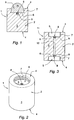
Fig. 1 shows a cross section through a cylindrical body and an elastomer sealing element of a magnet armature construction according to a first embodiment of the invention; -
Fig. 2 shows a perspective view of a cylindrical body of a magnet armature construction according to a first embodiment of the invention; -
Fig. 3 shows a cross section through a cylindrical body of a magnet armature construction according to a second embodiment of the magnet armature according to the invention; -
Fig. 4 shows an exemplary embodiment of a solenoid valve provided with a magnet armature construction according to the invention; -
Fig. 5 shows a vehicle provided with an anti-lock braking system with a magnet armature construction. - A first embodiment of a magnet armature construction according to the invention is denoted in its entirety in
Figs. 1 and 2 by thereference numeral 1. Theconstruction 1 comprises acylindrical body 2, made of ferromagnetic material. Thecylindrical body 2 comprises alateral surface 3 and twohead ends 4. Aseat 5 designed as a recess is provided in one of the head ends, which seat comprises abottom surface 6 and acircumferential wall 7. In the embodiment shown inFig. 1 , thecircumferential wall 7 tapers towards thehead end 4 of thecylindrical body 2. In the embodiment shown inFig. 2 , thecircumferential wall 7 is provided with a screw thread. Acavity 8 is provided in thecylindrical body 2 through thebottom surface 6 of theseat 5, so that thecavity 8 forms a further recess with respect to the head end. Thiscavity 8 is preferably cylinder-shaped. In the embodiment shown here, the longitudinal axis of the cylinder-shaped cavity 8 runs parallel to the longitudinal axis of thecylindrical body 2. In this case, this cavity is provided with ascrew thread 9, but may, in an embodiment which has not been shown, also be provided with other positively locking geometric formations, such as toothing. Anelastomer sealing element 10 is injection-moulded into theseat 5 and in thecavity 8, which is indicated in its entirety as being hatched. Theelastomer sealing element 10 preferably extends to above thehead end 4 of thecylindrical body 2. The diameter of the section of theelastomer sealing element 10 which extends above thehead end 4 is not larger than the diameter of thecylindrical body 2. -
Fig. 3 shows a second embodiment of a magnet armature construction according to the invention, designated by thereference numeral 11. Identical parts have been designated by the same numerals as those used inFigs. 1 and 2 . In this embodiment, thecavities 8, provided through theopposite bottom surfaces 6 of theseats 5 in the cylindrical body, are connected to each other by aninternal duct 12 in thecylindrical body 2. At least bothcavities 8 are provided with ascrew thread 9, but theinternal duct 12 may also be provided with a screw thread or another positively locking geometric formation. Two possible embodiments of thecircumferential wall 7 of theseat 5 are shown: a toothing and a combination of a toothing and acircumferential wall 7 tapering towards thehead end 4. - The possible embodiments of the
circumferential wall 7 andcavity 8 shown in these figures only serve as an example of the possible anchoring mechanisms for anchoring anelastic sealing element 10 to thecylindrical body 2 in a positively locking manner. - Possible dimensions for the
cylindrical body 2 are a total length of 20-25 mm and a diameter of 6.5-8 mm. Theseat 5 may have a diameter of 5-7 mm and is preferably 2-3 mm deep. Thecavity 8 may have a diameter of 2-3 mm and is preferably 2-4 mm deep. -
Fig. 4 shows asolenoid valve 20 in ahousing 25 with aduct 24. Thesolenoid valve 20 comprises acoil 21 and a cylinder-shaped shaft 22 for amagnet armature construction 1 within thecoil 21. Themagnet armature construction 1 is held in place by aspring 23. Themagnet armature construction 1 is identical to the construction illustrated inFig. 1 and therefore identical parts are designated by identical numbers. If sufficient current flows through thecoil 21 to overcome the spring force of thespring 23, themagnet armature construction 1, as a result of the force of the magnetic field which has been created, pushes thespring 23 downward as a result of which the valve at the top near theduct 24 is opened. -
Fig. 5 shows avehicle 30 equipped with ananti-lock braking system 31 provided with amagnet armature construction 1 according to the invention.
Claims (12)
- Magnet armature construction (1) comprising a ferromagnetic body (2), preferably a cylindrical body, having a lateral surface (3) and two head ends (4), in which at least one of the head ends (4) is provided with at least one seat (5) having a bottom surface (6) and a circumferential wall (7), which seat (5) is designed in such a manner that a positively locking anchoring with a sealing element is achieved by one or more first positively locking geometric formations being provided in the circumferential wall (7) of the seat (5), and an elastomer sealing element (10) which is injection-moulded into the seat (5),
characterized,
in that the positively locking anchoring is also produced by the fact that at least one cavity (8) is provided as a recess in the bottom surface (6) of the seat (5) in the ferromagnetic body (2), in that the circumferential wall (9) of the cavity (8) is provided with at least one second positively locking geometric formation, and in that a part of the elastomer sealing element (10) is injection-moulded in the cavity (8). - Magnet armature structure according to claim 1, in which, viewed in the direction of the plane of the bottom surface (6) of the seat (5), the cavity (8) is smaller than the bottom surface (6) of the seat (5).
- Magnet armature construction according to claim 1 or 2, in which the cavity (8) is cylinder-shaped.
- Magnet armature construction according to one or more of the preceding claims, in which the cavity (8) is positioned centrally in the seat.
- Magnet armature construction according to one or more of the preceding claims, in which the second positively locking geometric formation in the cavity (8) is a screw thread (9) or a toothing.
- Magnet armature construction according to claim 5, in which the cavity (8) is provided with a screw thread (9) of between M2 and M4.
- Magnet armature construction according to one or more of the preceding claims, in which the elastomer sealing element (10) extends above the head end (4) of the ferromagnetic body (2) .
- Magnet armature construction according to one or more of the preceding claims, in which both opposite head ends (4) of the ferromagnetic body (2) are provided with a said seat (5) each having a said cavity (8) provided as a recess in the bottom surface of said seat in the ferromagnetic body (2), in which the circumferential walls of both said cavities (8) are provided with said second positively locking geometric formations and in which both cavities (8) are connected to one another by an internal duct (12) through the ferromagnetic body (2) .
- Magnet armature construction according to one or more of the preceding claims, in which the cross section of the cavity (8), through a plane parallel to the bottom surface (6) of the seat (5), is not larger than 4 millimetres.
- Solenoid valve (20) provided with a magnet armature construction (1) according to one or more of the preceding claims 1-9.
- Anti-lock braking system (31) provided with a magnet armature construction (1) according to one or more of the preceding claims 1-9.
- Vehicle (30) with an anti-lock braking system (31) provided with a magnet armature construction (1) according to one or more of the preceding claims 1-9.
Applications Claiming Priority (2)
| Application Number | Priority Date | Filing Date | Title |
|---|---|---|---|
| NL1025947A NL1025947C2 (en) | 2004-04-14 | 2004-04-14 | Magnetic anchor. |
| NL1025947 | 2004-04-14 |
Publications (2)
| Publication Number | Publication Date |
|---|---|
| EP1587115A1 EP1587115A1 (en) | 2005-10-19 |
| EP1587115B1 true EP1587115B1 (en) | 2017-10-25 |
Family
ID=34938079
Family Applications (1)
| Application Number | Title | Priority Date | Filing Date |
|---|---|---|---|
| EP05075509.9A Expired - Lifetime EP1587115B1 (en) | 2004-04-14 | 2005-03-02 | Magnet armature |
Country Status (3)
| Country | Link |
|---|---|
| EP (1) | EP1587115B1 (en) |
| CN (1) | CN1691219B (en) |
| NL (1) | NL1025947C2 (en) |
Families Citing this family (1)
| Publication number | Priority date | Publication date | Assignee | Title |
|---|---|---|---|---|
| DE102006040342A1 (en) * | 2006-08-29 | 2008-03-06 | Robert Bosch Gmbh | Gas injector`s part arrangement, has separating unit for applying separation force on parts in unevenly distributed manner, where separation force resulting from tractive force is directed in direction perpendicular to contact surfaces |
Family Cites Families (3)
| Publication number | Priority date | Publication date | Assignee | Title |
|---|---|---|---|---|
| CN1136295A (en) * | 1993-10-08 | 1996-11-20 | 池东瀷 | Valve assembly for a hydraulic control device of an automotive anti-lock brake device |
| CN2224457Y (en) * | 1994-06-23 | 1996-04-10 | 煤炭科学研究总院上海分院 | Electromagnet with locking mechanism |
| DE10113316A1 (en) * | 2001-03-20 | 2002-09-26 | Wabco Gmbh & Co Ohg | Manufacturing process for magnetic armatures |
-
2004
- 2004-04-14 NL NL1025947A patent/NL1025947C2/en not_active IP Right Cessation
-
2005
- 2005-03-02 EP EP05075509.9A patent/EP1587115B1/en not_active Expired - Lifetime
- 2005-04-06 CN CN2005100640600A patent/CN1691219B/en not_active Expired - Lifetime
Non-Patent Citations (1)
| Title |
|---|
| None * |
Also Published As
| Publication number | Publication date |
|---|---|
| CN1691219A (en) | 2005-11-02 |
| NL1025947C2 (en) | 2005-10-17 |
| CN1691219B (en) | 2011-05-18 |
| EP1587115A1 (en) | 2005-10-19 |
Similar Documents
| Publication | Publication Date | Title |
|---|---|---|
| US5467961A (en) | Electromagnetically actuated valve | |
| CN104520947B (en) | Bistable electromagnetic adjustment equipment, armature assembly and camshaft adjustment device | |
| US8132590B2 (en) | Valve assembly with at least one transverse channel in a valve housing | |
| US20130292590A1 (en) | Solenoid valve, braking system | |
| US10371278B2 (en) | Systems and methods for an electromagnetic actuator having a unitary pole piece | |
| US20170307101A1 (en) | Valve Armature for a Solenoid Valve, and Valve Cartridge for a Solenoid Valve | |
| CN108700201A (en) | Solenoid valves, especially for motor vehicle air spring systems | |
| CN102124257A (en) | Control piston for slider valves and method for the production thereof | |
| JP2011503458A5 (en) | ||
| WO2016023757A1 (en) | Solenoid actuated fluid injection valve | |
| JP6770174B2 (en) | Valve mover and valve cartridge for solenoid valve | |
| EP1587115B1 (en) | Magnet armature | |
| CN1904418B (en) | Electromagnetic valve | |
| DE102016201474B4 (en) | Valve armature for a solenoid valve and valve cartridge for a solenoid valve | |
| JP5234037B2 (en) | solenoid valve | |
| KR102094630B1 (en) | Electromagnetic valve, especially for slip-regulated automotive brake systems | |
| US6073908A (en) | Solenoid valve | |
| JP3760328B2 (en) | solenoid | |
| KR20130129167A (en) | Solenoid valve and driver assistance device having such a valve | |
| US20140145098A1 (en) | Normally Closed Magnetic Valve | |
| CA2122857C (en) | Electromagnetically operated valve | |
| US20040251738A1 (en) | Magnet valve with reduced swiching noise | |
| JP2004360864A (en) | Structure to prevent incorrect assembly of solenoid valve assembly | |
| JP6913771B2 (en) | Hydraulic unit and controller for hydraulic braking system | |
| KR100673058B1 (en) | Solenoid Valve for Brake Control System |
Legal Events
| Date | Code | Title | Description |
|---|---|---|---|
| PUAI | Public reference made under article 153(3) epc to a published international application that has entered the european phase |
Free format text: ORIGINAL CODE: 0009012 |
|
| AK | Designated contracting states |
Kind code of ref document: A1 Designated state(s): AT BE BG CH CY CZ DE DK EE ES FI FR GB GR HU IE IS IT LI LT LU MC NL PL PT RO SE SI SK TR |
|
| AX | Request for extension of the european patent |
Extension state: AL BA HR LV MK YU |
|
| 17P | Request for examination filed |
Effective date: 20060116 |
|
| AKX | Designation fees paid |
Designated state(s): AT BE BG CH CY CZ DE DK EE ES FI FR GB GR HU IE IS IT LI LT LU MC NL PL PT RO SE SI SK TR |
|
| 17Q | First examination report despatched |
Effective date: 20140402 |
|
| GRAP | Despatch of communication of intention to grant a patent |
Free format text: ORIGINAL CODE: EPIDOSNIGR1 |
|
| INTG | Intention to grant announced |
Effective date: 20170524 |
|
| GRAS | Grant fee paid |
Free format text: ORIGINAL CODE: EPIDOSNIGR3 |
|
| GRAA | (expected) grant |
Free format text: ORIGINAL CODE: 0009210 |
|
| RAP1 | Party data changed (applicant data changed or rights of an application transferred) |
Owner name: HELVOET RUBBER & PLASTIC TECHNOLOGIES B.V. |
|
| AK | Designated contracting states |
Kind code of ref document: B1 Designated state(s): AT BE BG CH CY CZ DE DK EE ES FI FR GB GR HU IE IS IT LI LT LU MC NL PL PT RO SE SI SK TR |
|
| REG | Reference to a national code |
Ref country code: GB Ref legal event code: FG4D |
|
| REG | Reference to a national code |
Ref country code: CH Ref legal event code: EP |
|
| REG | Reference to a national code |
Ref country code: AT Ref legal event code: REF Ref document number: 940630 Country of ref document: AT Kind code of ref document: T Effective date: 20171115 |
|
| REG | Reference to a national code |
Ref country code: IE Ref legal event code: FG4D |
|
| REG | Reference to a national code |
Ref country code: DE Ref legal event code: R096 Ref document number: 602005052931 Country of ref document: DE |
|
| REG | Reference to a national code |
Ref country code: NL Ref legal event code: FP |
|
| REG | Reference to a national code |
Ref country code: LT Ref legal event code: MG4D |
|
| REG | Reference to a national code |
Ref country code: AT Ref legal event code: MK05 Ref document number: 940630 Country of ref document: AT Kind code of ref document: T Effective date: 20171025 |
|
| PG25 | Lapsed in a contracting state [announced via postgrant information from national office to epo] |
Ref country code: SE Free format text: LAPSE BECAUSE OF FAILURE TO SUBMIT A TRANSLATION OF THE DESCRIPTION OR TO PAY THE FEE WITHIN THE PRESCRIBED TIME-LIMIT Effective date: 20171025 Ref country code: LT Free format text: LAPSE BECAUSE OF FAILURE TO SUBMIT A TRANSLATION OF THE DESCRIPTION OR TO PAY THE FEE WITHIN THE PRESCRIBED TIME-LIMIT Effective date: 20171025 Ref country code: ES Free format text: LAPSE BECAUSE OF FAILURE TO SUBMIT A TRANSLATION OF THE DESCRIPTION OR TO PAY THE FEE WITHIN THE PRESCRIBED TIME-LIMIT Effective date: 20171025 Ref country code: FI Free format text: LAPSE BECAUSE OF FAILURE TO SUBMIT A TRANSLATION OF THE DESCRIPTION OR TO PAY THE FEE WITHIN THE PRESCRIBED TIME-LIMIT Effective date: 20171025 |
|
| PG25 | Lapsed in a contracting state [announced via postgrant information from national office to epo] |
Ref country code: IS Free format text: LAPSE BECAUSE OF FAILURE TO SUBMIT A TRANSLATION OF THE DESCRIPTION OR TO PAY THE FEE WITHIN THE PRESCRIBED TIME-LIMIT Effective date: 20180225 Ref country code: BG Free format text: LAPSE BECAUSE OF FAILURE TO SUBMIT A TRANSLATION OF THE DESCRIPTION OR TO PAY THE FEE WITHIN THE PRESCRIBED TIME-LIMIT Effective date: 20180125 Ref country code: AT Free format text: LAPSE BECAUSE OF FAILURE TO SUBMIT A TRANSLATION OF THE DESCRIPTION OR TO PAY THE FEE WITHIN THE PRESCRIBED TIME-LIMIT Effective date: 20171025 Ref country code: GR Free format text: LAPSE BECAUSE OF FAILURE TO SUBMIT A TRANSLATION OF THE DESCRIPTION OR TO PAY THE FEE WITHIN THE PRESCRIBED TIME-LIMIT Effective date: 20180126 |
|
| REG | Reference to a national code |
Ref country code: DE Ref legal event code: R097 Ref document number: 602005052931 Country of ref document: DE |
|
| PG25 | Lapsed in a contracting state [announced via postgrant information from national office to epo] |
Ref country code: CZ Free format text: LAPSE BECAUSE OF FAILURE TO SUBMIT A TRANSLATION OF THE DESCRIPTION OR TO PAY THE FEE WITHIN THE PRESCRIBED TIME-LIMIT Effective date: 20171025 Ref country code: CY Free format text: LAPSE BECAUSE OF FAILURE TO SUBMIT A TRANSLATION OF THE DESCRIPTION OR TO PAY THE FEE WITHIN THE PRESCRIBED TIME-LIMIT Effective date: 20171025 Ref country code: SK Free format text: LAPSE BECAUSE OF FAILURE TO SUBMIT A TRANSLATION OF THE DESCRIPTION OR TO PAY THE FEE WITHIN THE PRESCRIBED TIME-LIMIT Effective date: 20171025 Ref country code: DK Free format text: LAPSE BECAUSE OF FAILURE TO SUBMIT A TRANSLATION OF THE DESCRIPTION OR TO PAY THE FEE WITHIN THE PRESCRIBED TIME-LIMIT Effective date: 20171025 Ref country code: EE Free format text: LAPSE BECAUSE OF FAILURE TO SUBMIT A TRANSLATION OF THE DESCRIPTION OR TO PAY THE FEE WITHIN THE PRESCRIBED TIME-LIMIT Effective date: 20171025 |
|
| PG25 | Lapsed in a contracting state [announced via postgrant information from national office to epo] |
Ref country code: RO Free format text: LAPSE BECAUSE OF FAILURE TO SUBMIT A TRANSLATION OF THE DESCRIPTION OR TO PAY THE FEE WITHIN THE PRESCRIBED TIME-LIMIT Effective date: 20171025 Ref country code: PL Free format text: LAPSE BECAUSE OF FAILURE TO SUBMIT A TRANSLATION OF THE DESCRIPTION OR TO PAY THE FEE WITHIN THE PRESCRIBED TIME-LIMIT Effective date: 20171025 Ref country code: IT Free format text: LAPSE BECAUSE OF FAILURE TO SUBMIT A TRANSLATION OF THE DESCRIPTION OR TO PAY THE FEE WITHIN THE PRESCRIBED TIME-LIMIT Effective date: 20171025 |
|
| PLBE | No opposition filed within time limit |
Free format text: ORIGINAL CODE: 0009261 |
|
| STAA | Information on the status of an ep patent application or granted ep patent |
Free format text: STATUS: NO OPPOSITION FILED WITHIN TIME LIMIT |
|
| 26N | No opposition filed |
Effective date: 20180726 |
|
| REG | Reference to a national code |
Ref country code: CH Ref legal event code: PL |
|
| GBPC | Gb: european patent ceased through non-payment of renewal fee |
Effective date: 20180302 |
|
| PG25 | Lapsed in a contracting state [announced via postgrant information from national office to epo] |
Ref country code: SI Free format text: LAPSE BECAUSE OF FAILURE TO SUBMIT A TRANSLATION OF THE DESCRIPTION OR TO PAY THE FEE WITHIN THE PRESCRIBED TIME-LIMIT Effective date: 20171025 Ref country code: MC Free format text: LAPSE BECAUSE OF FAILURE TO SUBMIT A TRANSLATION OF THE DESCRIPTION OR TO PAY THE FEE WITHIN THE PRESCRIBED TIME-LIMIT Effective date: 20171025 |
|
| REG | Reference to a national code |
Ref country code: BE Ref legal event code: MM Effective date: 20180331 |
|
| REG | Reference to a national code |
Ref country code: IE Ref legal event code: MM4A |
|
| PG25 | Lapsed in a contracting state [announced via postgrant information from national office to epo] |
Ref country code: LU Free format text: LAPSE BECAUSE OF NON-PAYMENT OF DUE FEES Effective date: 20180302 |
|
| PG25 | Lapsed in a contracting state [announced via postgrant information from national office to epo] |
Ref country code: IE Free format text: LAPSE BECAUSE OF NON-PAYMENT OF DUE FEES Effective date: 20180302 |
|
| PG25 | Lapsed in a contracting state [announced via postgrant information from national office to epo] |
Ref country code: LI Free format text: LAPSE BECAUSE OF NON-PAYMENT OF DUE FEES Effective date: 20180331 Ref country code: GB Free format text: LAPSE BECAUSE OF NON-PAYMENT OF DUE FEES Effective date: 20180302 Ref country code: BE Free format text: LAPSE BECAUSE OF NON-PAYMENT OF DUE FEES Effective date: 20180331 Ref country code: CH Free format text: LAPSE BECAUSE OF NON-PAYMENT OF DUE FEES Effective date: 20180331 |
|
| PG25 | Lapsed in a contracting state [announced via postgrant information from national office to epo] |
Ref country code: FR Free format text: LAPSE BECAUSE OF NON-PAYMENT OF DUE FEES Effective date: 20180331 |
|
| PG25 | Lapsed in a contracting state [announced via postgrant information from national office to epo] |
Ref country code: TR Free format text: LAPSE BECAUSE OF FAILURE TO SUBMIT A TRANSLATION OF THE DESCRIPTION OR TO PAY THE FEE WITHIN THE PRESCRIBED TIME-LIMIT Effective date: 20171025 |
|
| PG25 | Lapsed in a contracting state [announced via postgrant information from national office to epo] |
Ref country code: PT Free format text: LAPSE BECAUSE OF FAILURE TO SUBMIT A TRANSLATION OF THE DESCRIPTION OR TO PAY THE FEE WITHIN THE PRESCRIBED TIME-LIMIT Effective date: 20171025 Ref country code: HU Free format text: LAPSE BECAUSE OF FAILURE TO SUBMIT A TRANSLATION OF THE DESCRIPTION OR TO PAY THE FEE WITHIN THE PRESCRIBED TIME-LIMIT; INVALID AB INITIO Effective date: 20050302 |
|
| P01 | Opt-out of the competence of the unified patent court (upc) registered |
Effective date: 20230512 |
|
| PGFP | Annual fee paid to national office [announced via postgrant information from national office to epo] |
Ref country code: NL Payment date: 20240322 Year of fee payment: 20 |
|
| PGFP | Annual fee paid to national office [announced via postgrant information from national office to epo] |
Ref country code: DE Payment date: 20240321 Year of fee payment: 20 |
|
| REG | Reference to a national code |
Ref country code: DE Ref legal event code: R071 Ref document number: 602005052931 Country of ref document: DE |
|
| REG | Reference to a national code |
Ref country code: NL Ref legal event code: MK Effective date: 20250301 |