EP1586995B1 - Contrôleur numérique pour contrôler l'execution de tâches de contrôle périodiques - Google Patents
Contrôleur numérique pour contrôler l'execution de tâches de contrôle périodiques Download PDFInfo
- Publication number
- EP1586995B1 EP1586995B1 EP04019064A EP04019064A EP1586995B1 EP 1586995 B1 EP1586995 B1 EP 1586995B1 EP 04019064 A EP04019064 A EP 04019064A EP 04019064 A EP04019064 A EP 04019064A EP 1586995 B1 EP1586995 B1 EP 1586995B1
- Authority
- EP
- European Patent Office
- Prior art keywords
- task
- control
- execution
- control task
- digital controller
- Prior art date
- Legal status (The legal status is an assumption and is not a legal conclusion. Google has not performed a legal analysis and makes no representation as to the accuracy of the status listed.)
- Expired - Lifetime
Links
Images


Classifications
-
- G—PHYSICS
- G06—COMPUTING OR CALCULATING; COUNTING
- G06F—ELECTRIC DIGITAL DATA PROCESSING
- G06F9/00—Arrangements for program control, e.g. control units
- G06F9/06—Arrangements for program control, e.g. control units using stored programs, i.e. using an internal store of processing equipment to receive or retain programs
- G06F9/46—Multiprogramming arrangements
- G06F9/48—Program initiating; Program switching, e.g. by interrupt
- G06F9/4806—Task transfer initiation or dispatching
- G06F9/4843—Task transfer initiation or dispatching by program, e.g. task dispatcher, supervisor, operating system
- G06F9/4881—Scheduling strategies for dispatcher, e.g. round robin, multi-level priority queues
- G06F9/4887—Scheduling strategies for dispatcher, e.g. round robin, multi-level priority queues involving deadlines, e.g. rate based, periodic
-
- G—PHYSICS
- G06—COMPUTING OR CALCULATING; COUNTING
- G06F—ELECTRIC DIGITAL DATA PROCESSING
- G06F9/00—Arrangements for program control, e.g. control units
- G06F9/06—Arrangements for program control, e.g. control units using stored programs, i.e. using an internal store of processing equipment to receive or retain programs
- G06F9/46—Multiprogramming arrangements
- G06F9/48—Program initiating; Program switching, e.g. by interrupt
- G06F9/4806—Task transfer initiation or dispatching
- G06F9/4812—Task transfer initiation or dispatching by interrupt, e.g. masked
Definitions
- the present invention relates to a digital controller for periodically executing a control task and an engine controller using the digital controller.
- a timer for starting the control task is disposed in a CPU, and periodic execution of the control task is achieved by periodically executing the control task in response to an interrupt signal periodically generated by the timer.
- the digital controller is widely used to control an actuator mechanism.
- a value indicating the state of the actuator to be controlled is measured using a sensor, and the measured value is captured in digital form by a CPU. The measured value is compared with a target value calculated by the CPU, and a control signal is created based on the comparison result. The actuator mechanism is controlled in accordance with the control signal.
- the digital controller In such a digital controller, it is required that the digital controller should have sufficiently high processing capability to ensure that the execution of the control task at each control cycle can be completed in a sufficiently short time compared with the control cycle.
- Various techniques have been proposed to further ensure that the control task is correctly executed at specified intervals.
- the processing load detection means detects a processing load greater than a threshold
- the correction control program is interrupted( JP2002-366374A ).
- the conventional digital controller which starts tasks in the above-described manner, has the following problems.
- control task is a time-dependent process including a calculation using a parameter associated with a time length (execution interval) as in the calculation of a speed on the basis of the position of a device to be controlled
- execution interval a time length
- the increase in task execution interval due to skipping of the task causes a loss of data in the calculation, which can cause a significant calculation error and thus a control error.
- skipping of execution of the control task results in skipping of counting. Another problem is that because it is needed to perform complicated processing such as management of priority of tasks or detection of task start requests, a large processing load associated with the task start process is imposed on the CPU, and thus a reduction occurs in processing power available for execution of the actual control task.
- the present invention provides a digital controller which may comprise execution control means for controlling execution of a control task so as to be executed at predetermined intervals, and/or interrupt disable means for, when the control task is being executed, disabling an interrupt for any other control task or any other task.
- the control task may be divided into two parts: a first task part that should be certainly executed at the predetermined intervals; and/or a second task part including the remaining part of the control task other than the first task part.
- execution control means may be provided wherein, when the execution control means detects an overrun of the control task as a result of a failure to complete the control task within the predetermined interval, a next execution of the control task is performed such that at least the first task part of the control task in the next execution is completed within the period of the next interval.
- the interrupt disable means disables an interrupt for any control task other than the control task being executed.
- any other task is not executed. This ensures that the control task is correctly executed at specified intervals.
- the first task part may be a task including a calculation using a parameter associated with the predetermined interval
- the second task part may be a task including a process using the result of the calculation performed in the first task part
- the execution control means may control execution of control tasks such that the execution control means disables interrupt for next execution of the control task until the execution of the second task part of the overrunning control task is completed, and, after completion of the second task part, the execution control means executes only the first task part of the control task in the next execution of the control task.
- the completion of the second task part ensures that the result of the control task can be used. In any situation, at least the first task part of the control task is executed without being skipped. Therefore, it is ensured that the first task part is executed as many times as needed, and thus no loss of time-dependent data occurs.
- the time-dependent data has an error equal to the delay due to the overrun.
- the error can be prevented as follows. If an interrupt signal for a next execution of the control task occurs when the second task part is being executed, the second task part is interrupted and only the first task part is executed in the next execution of the control task. This ensures that the first task part is executed at correct intervals, and thus no error occurs in the calculation result. In this case, the interrupted second task part can be resumed after completion of the first task part. This prevents a loss of control data due to the interrupt of the second task part.
- the digital controller according to the present invention ensures that the part of the control task that should be executed at specified intervals is correctly executed at specified intervals and thus no loss of time-dependent data occurs.
- Fig. 1 is a flow chart showing a process performed by a digital controller to control execution of control tasks, according to a first embodiment of the present invention.
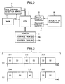
- Fig. 2 is a block diagram of the digital controller according to the present embodiment.
- the digital controller includes a CPU 1, a timer 2 for generating an interrupt signal at predetermined intervals, a memory 4 for storing a control task 3, an input circuit 5, an output circuit 6, and task overrun detection means 7.
- a device 8 to be controlled by the digital controller is connected with the CPU 1 via the input circuit 5 and the output circuit 6.
- the memory 4 is connected to the CPU 1 such that the memory 4 is accessible by the CPU 1.
- the memory stores a program of the control task 3 and also stores other data such as temporary data.
- the CPU 1 executes the control task 3 including the steps of acquiring the value indicating the state of the device 8 from the device via the input circuit 5, calculating the control amount to be applied to the device 8 on the basis of the acquired value indicating the state of the device 8, and outputting the determined control amount to the device 8 to be controlled via the output circuit 6.
- the value of the state of the device 8 is measured by a sensor disposed on the device 8 and is fed back to the CPU 1 via the input circuit 5.
- the CPU 1 includes task execution control means for controlling execution of the control task 3 in response to an interrupt signal 10 output from the timer 2, and interrupt disable means for disabling interrupts for the other tasks when the control task 3 is being executed.
- the interrupt signal 10 functions as a trigger that causes the control task 3 to start.
- the CPU 1 is capable of masking the interrupt signal 10 associated with the control task 3. When a mask command is executed by the CPU 1, the interrupt signal 10 is ignored even if the interrupt signal 10 is input.
- the control task 3 includes a control task 3a that is a first task part including a calculation using a calculation parameter associated with the interval T of the interrupt signal 10, and a control task 3b that is a second task part including a process using the result of the calculation performed in the control task 3a. That is, the control task 3a is a time-dependent task, and the control task 3b is a time-independent task that does not include a calculation parameter associated with the execution interval T.
- An example of a process of a time-dependent task is described below.
- the time-dependent task refers to a process including a calculation using a parameter associated with the execution interval. A specific example is a process of calculating the value indicating the state of a device to be controlled.
- processing is performed such that a model to be controlled converges to a value measured by the sensor.
- the model is given by a discrete differential equation represented in the form of a matrix equation. Because the speed is expressed by a differential term in the equation, the equation includes a coefficient indicating the execution interval of the control task. Therefore, to precisely calculate the state values, it is necessary to precisely control the execution interval. To meet the above requirement, the processing associated with the state observer is assigned to the control task 3a.
- control task 3a Another good example of the control task 3a is a watch dog timer for watching whether a program is correctly executed without runaway.
- the watch dog timer periodically outputs a signal to the outside to notify that the program is being correctly executed. If the task is skipped and no signal is output from the watch dog timer, it is incorrectly determined that an operation error occurs in the program, and thus the CPU 1 is reset.
- a process that needs precise control of the execution interval to achieve correct operation is advantageously assigned to the control task 3a.
- the interrupt signal 10 generated by the timer 2 is input to the task overrun detection means 7.
- the counter indicating the number of occurrences of the interrupt signal 10 is incremented.
- the counter is decremented in response to an access by the CPU 1, and the resultant counter value is output to the CPU 1. That is, the CPU 1 accesses the counter disposed in the task overrun detection means 7 to examine whether the counter value is equal to "0" to determine whether the control task 3 is completed within the specified interval T.
- a specific example of the task overrun detection means 7 will be described later.
- the execution control means for controlling execution of control tasks starts in response to an interrupt signal 10 generated by the timer 2.
- a further interrupt for the control task 3 or for any other task is disabled.
- the control tasks 3a and 3b of the control task 3 requested by the interrupt signal 10 are read from the memory 4 and executed.
- overrun detection data is read from the task overrun detection means 7, and the overrun detection means 7 is cleared.
- step S34 on the basis of the overrun detection data, it is determined whether there is an overrun. If no overrun is detected, the process exits. On the other hand, if an overrun is detected in the control task 3 being executed, the process proceeds to step S35. In step S35, only the control task 3a of the next control task 3 is executed. After completion of the control task 3a, an interrupt is enabled and the process exits.
- Fig. 3A shows a manner in which tasks are executed in the normal state without encountering an overrun.
- control tasks 3-1, 3-2, and 3-3 are started.
- occurrences of the interrupt signal 10 are represented by solid arrows in Fig. 3A .
- the control tasks 3a and 3b are denoted by (a) and (b), respectively.
- a further interrupt is masked if a task is started in response to an interrupt request (step S30 in Fig. 1 ).
- a task overrun can occur if the execution of the control task 3 needs a longer time than the predetermined interval T due to an increase in processing load.
- the execution of the control task 3 is skipped until the next interval, if no action is taken.
- the skipping of the control task 3 by one interval prevents a problem caused by unavailability of the task execution time or runaway of the program.
- the execution interval of the control task 3 temporarily becomes twice the normal execution interval.
- the skip of the control task results in a significant calculation error that can cause a significant control error.
- the control task 3 is divided into two parts, that is, the time-dependent control task 3a and the time-independent control task 3b, and detection of a task overrun is performed at the end of each execution of the control task 3. If a task overrun is detected in step S34 in Fig. 1 , only the time-dependent control task 3a is executed in step S35 in Fig. 1 .
- Fig. 3B shows an example of a manner in which execution of the control task 3 is controlled when a task overrun occurs. In response to an interrupt signal represented by a solid arrow in Fig. 3B , a control task 3-4 is started. In this specific example shown in Fig.
- a large processing load occurs when the control task 3-4 is being executed, and thus the control task 3-4 is not completed in a period T of the predetermined interval, that is, a task overrun occurs.
- An interrupt signal for execution of a next control task 3-5 following the control task 3-4 occurs as represented by a broken arrow in Fig. 3B . However, this interrupt signal is masked because of the occurrence of the task overrun, and thus the control task 3-5 is not started.
- the detection of a task overrun can be performed as follows.
- the control task 3a including the process using the parameter associated with the predetermined interval T is certainly executed in the interval, and thus no error occur in terms of the number of times the time-dependent task is executed. Therefore, the calculation error can be minimized, and the calculation accuracy of the control task 3b using the calculation result of the control task 3a can be improved. As a result, the control accuracy can be improved.
- the digital controller according to the present embodiment may be applied to an A/D conversion process in a state observer.
- the process associated with the state observer is assigned as a time-dependent task to the control task 3a.
- Fig. 4 shows an example of a manner in which input/output signals associated with the digital controller occur.
- the timer interrupt signal 10 is input at equal intervals, a delay in starting of the control task 3 can occur depending on the end time of the previous execution of the control task 3. More specifically, when a great increase in processing load occurs, a delay can occur in an SOC (Start Of Conversion) signal to the A/D converter relative to the interrupt signal 10, as is the case with a signal denoted by reference numeral 81 in Fig.
- SOC Start Of Conversion
- a similar delay also occurs in the output of the watch dog timer.
- the time-independent control task 3b is skipped in response to an occurrence of a task overrun, and the control output in interval 82 is maintained as the control output in interval 83 even if a change occurs in the input state value of the object to be controlled.
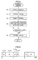
- Fig. 5 is a flow chart showing a process of controlling execution of control tasks according to a second embodiment of the present invention.
- interrupt signals that occur during execution of a control task are masked.
- execution of a time-dependent task at predetermined intervals is ensured by masking interrupt signals only during the execution of the control task 3a.
- the control-task execution control means starts in response to the interrupt signal 10 generated by the timer 2.
- step S50 a further interrupt for any other control task 3 or for any other task is disabled.
- step S51 only the control task 3a of the control task 3 associated with the interrupt is read from the memory 4 and executed. If the control task 3a is completed, then the disabling of interrupts is released in step S52.
- step S53 in order to determine whether the current control task 3a is completed within the interval, overrun detection data is read from the task overrun detection means 7 and the task overrun detection means is cleared.
- step S54 on the basis of the overrun detection data, it is determined whether a task overrun has occurred.
- step S55 the control task 3b of the current control task 3 is executed. After completion of the control task 3b, the process exits. On the other hand, if a task overrun is detected in step S54, the program immediately exits from the execution control routine.
- step S50 further interrupts are disabled, and the control task 3a of the next control task 3 is executed. That is, because disabling of interrupts is not performed in the previous execution of the control task 3b in step S55, the execution of the control task 3a is started immediately in response to the occurrence of the interrupt for the task 3. That is, unlike the embodiment shown in Fig. 1 , the interrupt signal 10 is not masked at all or masked only during the period in which the control task 3a is executed. After completion of the control task 3a, interrupts are enabled, and detection of a task overrun is performed.
- the control task 3a is started in response to a next interrupt signal 10 regardless of whether or not the control task 3b following the control task 3a is completed, because the interrupt signal 10 is not masked. This ensures that the control task 3a is correctly executed at the predetermined intervals without being skipped.
- a next execution of the control task 3a is started when the previous execution of the control task 3b is not yet completed, a task overrun is detected and the interrupted control task 3b is resumed after completion of the control task 3a.
- the execution time is adjusted depending on the situation, while precisely controlling the execution interval associated with the time-dependent task.
- a control task 3-11a is executed. After completion of the control task 3-11a, a control task 3-11b is immediately started. More specifically, when the control task 3-11a is completed, the task overrun detection means 7 is accessed to determine whether the control task 3-11a is completed within the predetermined period T (step S53). If no task overrun is detected (step S54), the control task 3-11b is started (step S55).
- a large processing load is imposed when the control task 3-11b is executed, and the control task 3-11b is not completed within the period T assigned to the control task 3. That is, an overrun occurs.
- the control task 3-11b because disabling of interrupts is released when the control task 3-11a is completed (step S52), the control task 3-11b is interrupted in response to an interrupt signal for a next control task 3-12a, and only the next control task 3-12a is executed. This allows the time-dependent task to be correctly executed at specified intervals. After completion of the control task 3-12a, the saved data associated with the interrupted control task 3-11b is restored, and the remaining control task 3-11b' is executed.
- the interval between the time-dependent control task 3-11a and the time-dependent control task 3-12a becomes exactly equal to the specified execution interval T. This prevents an error in the calculation using the parameter associated with the interval T.
- the technique of controlling tasks according to the present embodiment may also be applied to a digital controller including a real-time OS.
- interrupts are masked during execution of the time-dependent control task 3a, and the priority of interrupts is set to be higher than that of the time-independent control task 3b.
- Interrupts are enabled during execution of the control task 3b. Controlling of tasks in the above-described manner allows a program to be described in a small number of steps using the functions of the real-time OS, according to the present embodiment of the invention.
- the time-dependent control task 3a is started in response to a timer interrupt
- the time-independent control task 3b is started in response to a software interrupt from the control task 3a or simply in response to a subroutine call.
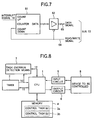
- Fig. 7 shows an embodiment of task overrun detection means 7.
- the task overrun detection means 7 includes a counter 61 and a bus buffer 62.
- the interrupt signal 10 is input to a count-up terminal of the counter 61.
- the counter value of the counter 61 is incremented by 1.
- the counter value of the counter 61 is output from a data output terminal of the counter 61 and supplied to the CPU 1 via the bus buffer 62 and a data bus 65 of a bus 12.
- a read/write signal 64 output from the CPU 1 is input via the bus 12 to a count-down terminal of the counter 61, and an inverted signal of the read/write signal 64 is input to the bus buffer 62.
- the counter is incremented by one when the control task is started in response to the interrupt signal 10 and is decremented by one when the control task is completed, the counter has a value of 0 as long as the control task is correctly executed. Thus, from the counter value, it is possible to determine whether the control task is correctly executed. If the counter has a value equal to or greater than 1, it can be concluded that a task overrun has occurred.
- the calculation result of the time-dependent task can be corrected by repeatedly performing the time-dependent as many times as the counter value.
- a flip-flop may be used instead of the counter.
- Fig. 8 shows another embodiment of a digital controller according to the present invention.
- the present embodiment is different from the embodiment described above with reference to Fig. 2 in that a timer 2 that defines intervals T at which to execute a control task is connected to a CPU 1 via a bus 11 such that a current time measured by the timer 2 can be read by the CPU 1 and also different in that task overrun detection means 7 is implemented by means of software.
- a control task is started, and a control task 3a and a control task 3b stored in a memory 4 are executed.
- the start time of the control task is read from the timer 2 and stored in the memory 4.
- the start time of the next execution of the control task may be determined by adding the interval T to the current start time, and may be stored in the memory 4.
- Figs. 3A and 3B The process of controlling execution of control tasks according to the present embodiment is described in further detail below with reference to a time chart shown in Figs. 3A and 3B .
- no interrupt signal is used, and thus solid arrows in Fig. 3 simply denote task start times based on the interval T.
- the start time of a control task 3-2 is calculated from the start time of a task 3-1.
- the timer value of the timer 2 is repeatedly read to detect the arrival of the start time of the control task 3-2. If the arrival of the start time of the control task 3-2 is detected, the control task 3-2 is started. This method of starting a task is generally known as polling.
- a control task 3-3 and following control tasks are also started in a similar manner. That is, the time indicated by the timer 2 is repeated read, and the read time is compared with start times. Each time the read time becomes equal to a start time, the control task 3 is executed thereby achieving periodic execution of the task 3.
- a task overrun occurs.
- the start time (denoted by a broken arrow) at which control task 3-5 should have been started after the control task 3-4 has already gone.
- a task overrun is detected when the indicated by the timer 2 is read at the end of the control task 3-4 and compared with the predetermined start time of the control task 3-5.
- a next control task 3-5 is handled such that only a part (a) of the control task 3-5 is executed to ensure that the time-dependent task is correctly executed at specified intervals.
- the next control task start time is determined by adding the specified interval T to the control task start time currently stored in the memory, and the determined control task start time is stored in the memory, thereby achieving execution of control task at equal intervals by means of polling using the timer 2.
- step S70 initialization is performed in step S70, and the routine enters a control loop.
- a timer value is read in step S71 and compared with a start time at which to start a control task, in next step S72. If the comparison in step S72 indicates that the timer value has not yet reached the execution start time, the process returns to step S71. However, if the timer value is exactly equal to the execution start time, the process proceeds to step S73. In step S73, a next execution start time is stored. Furthermore, in steps S74 and S75, specified control tasks 3a and 3b are executed. After completion of those tasks 3a and 3b, the process returns to step S71.
- step S72 determines whether the timer value has already reached the execution start time. If it is determined in step S72 that the timer value has already reached the execution start time, the process proceeds to step S76.
- step S76 a next execution time is stored.
- step S77 only the control task 3a, which is a time-dependent task, is executed in a state in which an overrun has occurred.
- control tasks are started by means of polling using the timer. This makes it possible to correctly execute the time-dependent control task 3a at controlled intervals with a less overhead time than needed in the technique based on interrupts.
- the CPU 1 controls the execution interval of control tasks on the basis of the time read from the timer 2 via the bus 11.
- this process may be performed by means of hardware including a register and a comparator.
- the time read from the timer 2 is automatically loaded into the register so that, simply by accessing the output of the comparator, the CPU 1 can easily acquire the flag value indicating one of three states, that is, a first state in which the execution start time has not yet reached, a second state in which the execution start time has just reached, and a third state in which the execution start time has gone. This allows a further reduction in processing load due to the program of controlling execution of task.
- the task overrun detection means 7 is realized by means of hardware including the counter 61 for counting the number of interrupts generated by the hardware timer 2.
- the task overrun detection means 7 may be realized by means of software.
- an interrupt is generated by the hardware timer 2
- a task is not directly started, but a small interrupt routine called an interrupt handler is started.
- the interrupt handling process including starting of a task and masking of an interrupt is performed by the interrupt handler realized by means of software.
- the task overrun detection means is implemented in the form of a program in the interrupt handler, and the number of interrupts is counted and stored in the memory, thereby achieving the similar functions to those achieved in the previous embodiments. This allows a simplification of hardware and a reduction in cost, although a slight increase in processing overhead occurs.
- Fig. 10 shows a system in which a digital controller according to the present invention is used to control a vehicle.
- an engine controller 91 is responsible for control of an engine 96 and is realized by the digital controller according to one of above-described embodiments of the present invention.
- the values indicating the state of the engine can be precisely measured at predetermined intervals. Because the measurement values do not include a significant error, the engine can be precisely controlled on the basis of the measured values.
- the engine controller 91 calculates the state values from information supplied from an engine state sensor 94, by means of a state observer realized by executing a time-dependent control task 3a. Furthermore, in accordance with a target value indicated by a control command, the engine controller 91 also calculates a control amount by executing a time-independent control task 3b. The calculated control amount is output to an injector 92 or an electronically controlled throttle 93. In accordance with control amount, a physical amount such as a fuel injection quantity or an intake air quantity is controlled thereby controlling the engine 96.
- the digital controller according to the present embodiment is capable of performing high-load control tasks and high-precision calculations of the state values varying quickly with time.
- the engine 96 includes a crank angle sensor 95.
- the digital controller according to the present invention can also be used to periodically execute a control task in response to an interrupt generated in the form of a crack angle pulse by the crank angle sensor 95.
- the digital controller according to the present invention can be used to control an actuator mechanism such as an electromagnetic valve that needs to be controlled at very short intervals. That is, the digital controller according to the present invention is capable of detecting the state value by performing periodic high-speed calculations associated with a state observer based on the lift sensor while calculating the driving current by executing a control task at very short intervals.
- a cruse controller 97 acquires state values such as a vehicle speed via a CAN (Controller Area Network) bus 98 and outputs a control command such as an engine torque value request command or a speed change request.
- state values such as a vehicle speed via a CAN (Controller Area Network) bus 98
- control command such as an engine torque value request command or a speed change request.
- the digital controller can also be used to control a device connected via a communication line or a network as in the present example.
- the digital controller according to the present invention may also be employed in general applications such as a servo control of a mechatronic apparatus such as an industrial robot. In controlling of a mechanical device, it is indispensable to perform calculations associated with a state observer based on mechanical motion analysis.
- the digital controller according to the present invention is capable of performing the servo control process while maintaining the precise execution intervals at which the calculation associated with the state observer is performed.
- the digital controller according to the present invention may also be applied to a communication device such as a facsimile machine.
- a process such as an asynchronous communication task that needs to be performed at precise intervals is assigned to a time-dependent task, and other general processes such as a printing process are assigned to a time-independent task, thereby allowing a high-efficiency use of processing power of the CPU 1.
- the digital controller according to the present invention as described above with reference specific embodiments, has the following advantages.
Landscapes
- Engineering & Computer Science (AREA)
- Software Systems (AREA)
- Theoretical Computer Science (AREA)
- Physics & Mathematics (AREA)
- General Engineering & Computer Science (AREA)
- General Physics & Mathematics (AREA)
- Combined Controls Of Internal Combustion Engines (AREA)
- Control By Computers (AREA)
Claims (10)
- Contrôleur numérique comprenant un moyen de contrôle d'exécution permettant de contrôler l'exécution d'une tâche de contrôle (3) de manière à ce qu'elle soit exécutée à des intervalles prédéterminés et un moyen de désactivation d'interruption permettant, quand la tâche de contrôle (3) est exécutée, de désactiver une interruption pour toute autre tâche de contrôle et toute autre tâche, caractérisé en ce que
ladite tâche de contrôle (3) est divisée en deux parties : une première partie de tâche (3a) qui devrait être exécutée avec certitude aux intervalles prédéterminés et incluant un calcul utilisant un paramètre associé à l'intervalle prédéterminé ; et une seconde partie de tâche (3b) incluant la partie restante de la tâche de contrôle autre que la première partie de tâche et incluant un traitement utilisant le résultat du calcul effectué dans la première partie de tâche (3a) ; et
ledit moyen de contrôle d'exécution, quand le moyen de contrôle d'exécution détecte une surcharge de la tâche de contrôle (3) suite à une incapacité à achever la tâche de contrôle (3) dans l'intervalle prédéterminé, accomplit la prochaine exécution de la tâche de contrôle (3) de sorte que seule la première partie de tâche (3a) de la tâche de contrôle (3) au cours de la prochaine exécution soit achevée dans la période du prochain intervalle. - Contrôleur numérique selon la revendication 1, dans lequel le moyen de contrôle d'exécution désactive l'interruption pour la prochaine exécution de la tâche de contrôle (3) jusqu'à ce que l'exécution de la seconde partie de tâche (3b) de la tâche de contrôle en surcharge soit achevée et, après l'accomplissement de la seconde partie de tâche (3b), le moyen de contrôle d'exécution n'exécute que la première partie de tâche (3a) de la tâche de contrôle (3) au cours de la prochaine exécution de la tâche de contrôle (3).
- Contrôleur numérique selon au moins l'une des revendications 1 ou 2, dans lequel, si un signal d'interruption pour la prochaine exécution de la tâche de contrôle (3) se produit quand la seconde partie de tâche (3b) de la tâche de contrôle en surcharge est exécutée, le moyen de contrôle d'exécution interrompt l'exécution de la seconde partie de tâche (3b) et n'exécute que la première partie de tâche (3a) de la tâche de contrôle (3) au cours de la prochaine exécution de la tâche de contrôle (3).
- Contrôleur numérique selon la revendication 3, dans lequel, après l'accomplissement de la première partie de tâche (3a), la seconde partie de tâche (3b) est reprise.
- Contrôleur numérique selon au moins l'une des revendications 1 à 4, dans lequel
une surcharge de tâche est détectée en utilisant un circuit de maintien qui est déclenché en réponse à un signal d'interruption (10) pour la tâche de contrôle (3) et remis à zéro quand la tâche de contrôle (3) démarrée en réponse à ce signal d'interruption (10) est achevée ; et
en réponse à un signal d'interruption (10) pour la prochaine exécution de la tâche de contrôle (3), le moyen de contrôle d'exécution détecte l'apparition d'une surcharge de tâche sur la base du contenu du circuit de maintien. - Contrôleur numérique selon au moins l'une des revendications 1 à 5, dans lequel une surcharge de tâche est détectée en utilisant un compteur qui est incrémenté en réponse à un signal d'interruption pour la tâche de contrôle et qui est décrémenté quand la tâche de contrôle est achevée.
- Contrôleur numérique selon au moins l'une des revendications 1 à 6, dans lequel une surcharge de tâche est détectée sur la base du nombre stocké dans une mémoire (4), le nombre étant incrémenté chaque fois que la tâche de contrôle (3) est démarrée et décrémenté quand la tâche de contrôle est achevée.
- Contrôleur numérique selon au moins l'une des revendications 1 à 7, dans lequel
le signal d'interruption (10) est généré périodiquement par une minuterie (2) ; et
une surcharge de tâche est détectée en utilisant un comparateur qui compare le temps écoulé compté par la minuterie (2) avec l'intervalle prédéterminé et produit un signal adoptant un état parmi trois états en fonction du résultat de comparaison, un premier état parmi les trois états indiquant que le temps écoulé n'a pas encore atteint un temps de départ d'exécution, un second état indiquant que le temps écoulé est égal au temps de départ d'exécution et un troisième état indiquant que le temps écoulé a déjà atteint le temps de départ d'exécution. - Contrôleur numérique selon la revendication 1, caractérisé par un moyen de contrôle d'exécution permettant de contrôler l'exécution d'une tâche de contrôle (3) en lisant périodiquement une valeur de minuterie à partir d'une minuterie (2), en comparant la valeur de minuterie avec un temps de départ d'exécution prédéterminé, en exécutant la tâche de contrôle (3) chaque fois que la valeur de minuterie atteint le temps de départ d'exécution prédéterminé de sorte que toute tâche autre que la tâche de contrôle (3) ne soit pas exécutée, ce qui permet d'exécuter la tâche de contrôle (3) à des intervalles prédéterminés.
- Dispositif de contrôle de moteur utilisant un contrôleur numérique selon au moins l'une des revendications 1 à 9.
Applications Claiming Priority (2)
| Application Number | Priority Date | Filing Date | Title |
|---|---|---|---|
| JP2004119124A JP2005301812A (ja) | 2004-04-14 | 2004-04-14 | デジタル制御装置およびこれを用いたエンジン制御装置 |
| JP2004119124 | 2004-04-14 |
Publications (2)
| Publication Number | Publication Date |
|---|---|
| EP1586995A1 EP1586995A1 (fr) | 2005-10-19 |
| EP1586995B1 true EP1586995B1 (fr) | 2008-10-29 |
Family
ID=34926132
Family Applications (1)
| Application Number | Title | Priority Date | Filing Date |
|---|---|---|---|
| EP04019064A Expired - Lifetime EP1586995B1 (fr) | 2004-04-14 | 2004-08-11 | Contrôleur numérique pour contrôler l'execution de tâches de contrôle périodiques |
Country Status (4)
| Country | Link |
|---|---|
| US (1) | US20050235085A1 (fr) |
| EP (1) | EP1586995B1 (fr) |
| JP (1) | JP2005301812A (fr) |
| DE (1) | DE602004017420D1 (fr) |
Families Citing this family (12)
| Publication number | Priority date | Publication date | Assignee | Title |
|---|---|---|---|---|
| US7210053B2 (en) * | 2004-08-31 | 2007-04-24 | Emc Corporation | Systems and methods for assigning tasks to derived timers of various resolutions in real-time systems to maximize timer usage |
| JP5246062B2 (ja) * | 2009-06-25 | 2013-07-24 | トヨタ自動車株式会社 | 車載制御装置 |
| JP5633501B2 (ja) * | 2011-11-04 | 2014-12-03 | トヨタ自動車株式会社 | 制御装置および制御方法 |
| BR112017003478A2 (pt) * | 2014-09-25 | 2018-03-20 | Nsk Ltd. | aparelho de controle e método de controle de equipamento eletrônico em um veículo |
| JP2016113968A (ja) * | 2014-12-16 | 2016-06-23 | アイシン精機株式会社 | 車両用制御装置および制御方法 |
| US9658913B2 (en) * | 2015-04-27 | 2017-05-23 | GM Global Technology Operations LLC | Method for continuous operation of controller functionality during transient frame overrun |
| WO2017084044A1 (fr) * | 2015-11-18 | 2017-05-26 | 深圳市大疆创新科技有限公司 | Procédé et appareil d'adressage de bus et procédé et appareil de suggestion d'informations |
| JP2018055579A (ja) * | 2016-09-30 | 2018-04-05 | 株式会社デンソー | 電子制御装置 |
| DE102018205390A1 (de) * | 2018-04-10 | 2019-10-10 | Robert Bosch Gmbh | Verfahren und Vorrichtung zur Fehlerbehandlung in einer Kommunikation zwischen verteilten Software Komponenten |
| DE102018205392A1 (de) * | 2018-04-10 | 2019-10-10 | Robert Bosch Gmbh | Verfahren und Vorrichtung zur Fehlerbehandlung in einer Kommunikation zwischen verteilten Software Komponenten |
| WO2020080239A1 (fr) * | 2018-10-19 | 2020-04-23 | ソニー株式会社 | Procédé de traitement d'informations, dispositif de traitement d'informations et programme de traitement d'informations |
| KR102619973B1 (ko) * | 2018-11-28 | 2024-01-02 | 삼성전자주식회사 | 복수의 태스크들을 스케줄링하는 전자 장치 및 그의 동작 방법 |
Family Cites Families (9)
| Publication number | Priority date | Publication date | Assignee | Title |
|---|---|---|---|---|
| JP2520544B2 (ja) * | 1991-09-26 | 1996-07-31 | インターナショナル・ビジネス・マシーンズ・コーポレイション | タスクのオ―バ―ラン状態を監視する方法及びタスク実行サイクルのオ―バ―ランを検出する装置 |
| DE19500957A1 (de) * | 1994-07-19 | 1996-01-25 | Bosch Gmbh Robert | Verfahren zur Steuerung von technischen Vorgängen oder Prozessen |
| DE19827430C2 (de) * | 1997-07-22 | 2001-07-12 | Siemens Ag | Überwachungsverfahren zur Erkennung von Endlosschleifen und blockierten Prozessen in einem Rechnersystem |
| US6148324A (en) * | 1998-01-05 | 2000-11-14 | Lucent Technologies, Inc. | Prioritized load balancing among non-communicating processes in a time-sharing system |
| IL124594A0 (en) * | 1998-05-21 | 1998-12-06 | Nds Ltd | Context saving system |
| US6065089A (en) * | 1998-06-25 | 2000-05-16 | Lsi Logic Corporation | Method and apparatus for coalescing I/O interrupts that efficiently balances performance and latency |
| JP2002099432A (ja) * | 2000-09-22 | 2002-04-05 | Sony Corp | 演算処理システム及び演算処理制御方法、タスク管理システム及びタスク管理方法、並びに記憶媒体 |
| US20030009508A1 (en) * | 2001-06-26 | 2003-01-09 | Troia Terry A. | Method and system for providing processor task scheduling |
| US6980925B2 (en) * | 2003-10-03 | 2005-12-27 | Kelsey-Hayes Company | Real-time signal processing for vehicle tire load monitoring |
-
2004
- 2004-04-14 JP JP2004119124A patent/JP2005301812A/ja active Pending
- 2004-08-11 DE DE602004017420T patent/DE602004017420D1/de not_active Expired - Lifetime
- 2004-08-11 EP EP04019064A patent/EP1586995B1/fr not_active Expired - Lifetime
- 2004-08-20 US US10/921,981 patent/US20050235085A1/en not_active Abandoned
Also Published As
| Publication number | Publication date |
|---|---|
| JP2005301812A (ja) | 2005-10-27 |
| EP1586995A1 (fr) | 2005-10-19 |
| DE602004017420D1 (de) | 2008-12-11 |
| US20050235085A1 (en) | 2005-10-20 |
Similar Documents
| Publication | Publication Date | Title |
|---|---|---|
| EP1586995B1 (fr) | Contrôleur numérique pour contrôler l'execution de tâches de contrôle périodiques | |
| JP4241462B2 (ja) | 制御ユニットおよびマイクロコンピュータ | |
| US20040039935A1 (en) | Method and device for measuring the execution time of a real task in a real time system | |
| CN106033345A (zh) | Cpu使用率的控制方法和装置 | |
| US20080282248A1 (en) | Electronic computing device capable of specifying execution time of task, and program therefor | |
| US6543000B1 (en) | Interrupt management system with timers and controller able to detect the interrupt missed and generate appropriate warning signal for error handling | |
| US9513969B2 (en) | Method for the management of task execution in a computer system | |
| JPH11232148A (ja) | 計算機の負荷率計測方法及び計測システム | |
| JP3663950B2 (ja) | 自動車用電子制御装置 | |
| EP1248192B1 (fr) | Dispositif pour l'exécution des processus avec une fonction pour limiter des références aux données | |
| CN112256419B (zh) | 一种基于定时器时钟控制的嵌入式系统多任务调度方法 | |
| Rivas et al. | Evaluation of new posix real-time operating systems services for small embedded platforms | |
| CN117707798A (zh) | 多线程并发状态下的死锁消除方法、装置、设备及介质 | |
| US20230004396A1 (en) | Constrained carries on speculative counters | |
| CN114818570A (zh) | 一种基于蒙特卡罗仿真的嵌入式系统时序分析方法 | |
| CN113419917A (zh) | 一种嵌入式操作系统任务和中断的cpu负载率计算方法 | |
| US7793295B2 (en) | Setting bandwidth limiter and adjusting execution cycle of second device using one of the GBL classes selected based on priority of task from first device | |
| CN121418391B (zh) | 一种用于消息管理的数据处理系统 | |
| CN114528793B (zh) | 一种对Verilog HDL进行行为仿真的方法 | |
| JP6729430B2 (ja) | 電子制御装置 | |
| Zhou et al. | Rate-monotonic scheduling in the presence of timing unpredictability | |
| Zamorano et al. | Implementing execution-time clocks for the Ada Ravenscar profile | |
| US11928075B2 (en) | Method of transmitting data and command through RS232 serial port | |
| JP3506919B2 (ja) | 全命令トレース時のタイマー制御方法 | |
| JPH04118704A (ja) | イベント駆動型車両制御用コンピュータ |
Legal Events
| Date | Code | Title | Description |
|---|---|---|---|
| PUAI | Public reference made under article 153(3) epc to a published international application that has entered the european phase |
Free format text: ORIGINAL CODE: 0009012 |
|
| AK | Designated contracting states |
Kind code of ref document: A1 Designated state(s): AT BE BG CH CY CZ DE DK EE ES FI FR GB GR HU IE IT LI LU MC NL PL PT RO SE SI SK TR |
|
| AX | Request for extension of the european patent |
Extension state: AL HR LT LV MK |
|
| 17P | Request for examination filed |
Effective date: 20060213 |
|
| AKX | Designation fees paid |
Designated state(s): DE FR |
|
| 17Q | First examination report despatched |
Effective date: 20061113 |
|
| GRAP | Despatch of communication of intention to grant a patent |
Free format text: ORIGINAL CODE: EPIDOSNIGR1 |
|
| RIC1 | Information provided on ipc code assigned before grant |
Ipc: G06F 9/48 20060101AFI20080227BHEP |
|
| GRAS | Grant fee paid |
Free format text: ORIGINAL CODE: EPIDOSNIGR3 |
|
| RAP1 | Party data changed (applicant data changed or rights of an application transferred) |
Owner name: HITACHI, LTD. |
|
| GRAA | (expected) grant |
Free format text: ORIGINAL CODE: 0009210 |
|
| AK | Designated contracting states |
Kind code of ref document: B1 Designated state(s): DE FR |
|
| REF | Corresponds to: |
Ref document number: 602004017420 Country of ref document: DE Date of ref document: 20081211 Kind code of ref document: P |
|
| PLBE | No opposition filed within time limit |
Free format text: ORIGINAL CODE: 0009261 |
|
| STAA | Information on the status of an ep patent application or granted ep patent |
Free format text: STATUS: NO OPPOSITION FILED WITHIN TIME LIMIT |
|
| 26N | No opposition filed |
Effective date: 20090730 |
|
| PGFP | Annual fee paid to national office [announced via postgrant information from national office to epo] |
Ref country code: DE Payment date: 20090831 Year of fee payment: 6 |
|
| REG | Reference to a national code |
Ref country code: FR Ref legal event code: ST Effective date: 20100430 |
|
| PG25 | Lapsed in a contracting state [announced via postgrant information from national office to epo] |
Ref country code: FR Free format text: LAPSE BECAUSE OF NON-PAYMENT OF DUE FEES Effective date: 20090831 |
|
| REG | Reference to a national code |
Ref country code: DE Ref legal event code: R119 Ref document number: 602004017420 Country of ref document: DE Effective date: 20110301 |
|
| PG25 | Lapsed in a contracting state [announced via postgrant information from national office to epo] |
Ref country code: DE Free format text: LAPSE BECAUSE OF NON-PAYMENT OF DUE FEES Effective date: 20110301 |