EP1586885B1 - Vehicle speed control system for a vehicle on a chassis dynamometer - Google Patents
Vehicle speed control system for a vehicle on a chassis dynamometer Download PDFInfo
- Publication number
- EP1586885B1 EP1586885B1 EP05008061A EP05008061A EP1586885B1 EP 1586885 B1 EP1586885 B1 EP 1586885B1 EP 05008061 A EP05008061 A EP 05008061A EP 05008061 A EP05008061 A EP 05008061A EP 1586885 B1 EP1586885 B1 EP 1586885B1
- Authority
- EP
- European Patent Office
- Prior art keywords
- vehicle speed
- command
- driving force
- vehicle
- output
- Prior art date
- Legal status (The legal status is an assumption and is not a legal conclusion. Google has not performed a legal analysis and makes no representation as to the accuracy of the status listed.)
- Ceased
Links
- 230000001133 acceleration Effects 0.000 claims description 27
- 230000004044 response Effects 0.000 claims description 16
- 238000012937 correction Methods 0.000 claims description 13
- 230000003466 anti-cipated effect Effects 0.000 claims description 11
- 238000001514 detection method Methods 0.000 claims description 4
- 230000005540 biological transmission Effects 0.000 description 33
- 238000000034 method Methods 0.000 description 7
- 238000004364 calculation method Methods 0.000 description 6
- 238000001390 forced Rayleigh scattering spectroscopy Methods 0.000 description 6
- 230000006870 function Effects 0.000 description 6
- 238000012360 testing method Methods 0.000 description 6
- 238000010586 diagram Methods 0.000 description 5
- 238000006243 chemical reaction Methods 0.000 description 4
- 230000008859 change Effects 0.000 description 3
- 238000005259 measurement Methods 0.000 description 3
- 230000008569 process Effects 0.000 description 2
- 230000008901 benefit Effects 0.000 description 1
- 238000010276 construction Methods 0.000 description 1
- 238000007796 conventional method Methods 0.000 description 1
- 239000000498 cooling water Substances 0.000 description 1
- 230000000994 depressogenic effect Effects 0.000 description 1
- 238000004088 simulation Methods 0.000 description 1
- 238000012546 transfer Methods 0.000 description 1
Images


Classifications
-
- G—PHYSICS
- G01—MEASURING; TESTING
- G01M—TESTING STATIC OR DYNAMIC BALANCE OF MACHINES OR STRUCTURES; TESTING OF STRUCTURES OR APPARATUS, NOT OTHERWISE PROVIDED FOR
- G01M17/00—Testing of vehicles
- G01M17/007—Wheeled or endless-tracked vehicles
- G01M17/0072—Wheeled or endless-tracked vehicles the wheels of the vehicle co-operating with rotatable rolls
-
- A—HUMAN NECESSITIES
- A47—FURNITURE; DOMESTIC ARTICLES OR APPLIANCES; COFFEE MILLS; SPICE MILLS; SUCTION CLEANERS IN GENERAL
- A47K—SANITARY EQUIPMENT NOT OTHERWISE PROVIDED FOR; TOILET ACCESSORIES
- A47K3/00—Baths; Douches; Appurtenances therefor
- A47K3/02—Baths
- A47K3/022—Baths specially adapted for particular use, e.g. for washing the feet, for bathing in sitting position
-
- A—HUMAN NECESSITIES
- A61—MEDICAL OR VETERINARY SCIENCE; HYGIENE
- A61H—PHYSICAL THERAPY APPARATUS, e.g. DEVICES FOR LOCATING OR STIMULATING REFLEX POINTS IN THE BODY; ARTIFICIAL RESPIRATION; MASSAGE; BATHING DEVICES FOR SPECIAL THERAPEUTIC OR HYGIENIC PURPOSES OR SPECIFIC PARTS OF THE BODY
- A61H39/00—Devices for locating or stimulating specific reflex points of the body for physical therapy, e.g. acupuncture
- A61H39/04—Devices for pressing such points, e.g. Shiatsu or Acupressure
-
- A—HUMAN NECESSITIES
- A61—MEDICAL OR VETERINARY SCIENCE; HYGIENE
- A61H—PHYSICAL THERAPY APPARATUS, e.g. DEVICES FOR LOCATING OR STIMULATING REFLEX POINTS IN THE BODY; ARTIFICIAL RESPIRATION; MASSAGE; BATHING DEVICES FOR SPECIAL THERAPEUTIC OR HYGIENIC PURPOSES OR SPECIFIC PARTS OF THE BODY
- A61H2205/00—Devices for specific parts of the body
- A61H2205/12—Feet
Definitions
- the present invention relates to a vehicle speed control system applied to a vehicle driven on a chassis dynamometer.
- a known vehicle speed control system for a vehicle driven on a chassis dynamometer mainly by a feedback loop tends to be put in a situation that it is difficult to improve a responsibility of a vehicle seed control due to a response delay, a play and a hysteresis of the tested vehicle.
- Japanese Published Patent Application No. 7-325019 discloses a feed-forward control method using an inverse function MG(S) -1 of a transfer function of a tested vehicle. Further in order to solve an error generated during a period of obtaining the inverse function MG(S) -1 , there is provided a vehicle model compensation control circuit so as to output a correction command for correcting an accelerator stroke command outputted from the inverse function circuit when a deviation is caused between a vehicle speed command and a vehicle speed.
- Japanese Published Patent Application No. 2003-213990 discloses another feed-forward control method arranged to compensate an error of a feed-forward control by adding a quantity corresponding to a running resistance of a tested vehicle in a feedback control circuit.
- US 5,195,038 discloses a control system for a vehicle on a chassis dynamometer in which a throttle angle of an engine is adjusted based on the addition of three throttle angle components.
- a first throttle angle component comes from a throttle predictive angle calculation part and is selected from a map based on a target vehicle velocity signal and a change position signal from an operation pattern generator.
- a second throttle angle component is determined based on an acceleration indicated by the target vehicle speed signal by a throttle angle corresponding to acceleration calculation part and a third throttle angle component is determined based on a difference between the target vehicle speed and an actual vehicle speed by an error correction controller.
- EP 1 048 944 A2 discloses an engine testing apparatus comprising an engine dynamometer used to simulate an actual vehicle running on a chassis dynamometer.
- the system comprises a rotation control system which controls the operation amount of the engine dynamometer based on an engine target rotation number signal Rr that is calculated based on a target vehicle speed Vr and subjected to a delay correcting circuit.
- the rotation control system comprises a delay correcting circuit.
- the apparatus further comprises a simulation vehicle control system which adjusts a throttle opening of the engine.
- US 6,345,542 B1 discloses an apparatus controlling an electric inertia of a chassis dynamometer so as to simulate a running resistance of a vehicle under test.
- the dynamometer control apparatus comprises a target velocity calculating section which calculates a target vehicle velocity vR. A comparison between the calculated target vehicle velocity and the actual vehicle velocity is used to correct the control delay.
- US 2002/0082760 A1 discloses a driving force control apparatus which controls the throttle opening of an engine of a vehicle based on a target driving force and a target engine torque calculated from a position of an accelerator of the vehicle.
- An aspect of the present invention resides in a vehicle speed control system for driving a vehicle on a chassis dynamometer according to claim 1.
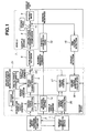
- Fig. 1 is a block diagram showing a vehicle speed control system according to a first embodiment of the present invention.
- Fig. 2 is a block diagram showing the vehicle speed control system of Fig. 1 in detail.
- Fig. 3 is a three-dimensional graph showing a driving force characteristic map of the first embodiment.
- Fig. 4 is a block diagram showing a conversion circuit for converting a driving force command and a detected vehicle speed in the vehicle speed control system of a second embodiment.
- Fig. 5 is a block diagram showing a braking timing automatic determination circuit in the vehicle speed control system of a third embodiment.
- a vehicle speed control system according to the present invention.
- the first embodiment is specifically arranged to execute a vehicle speed control based on a model that a driver manipulates an accelerator a vehicle.
- This vehicle speed control system is applied to a vehicle 7 tested on a chassis dynamometer (CDM) 10.
- CDM chassis dynamometer
- Fig. 1 is a block diagram showing a vehicle speed control system of a first embodiment according to the present invention.
- the vehicle speed control system comprises a vehicle speed commanding device 1, a vehicle speed command anticipating section 2, a vehicle mass setting section 3, a driving force calculating section 4 and the driving force characterizing section 5.
- the vehicle speed commanding device 1 outputs a vehicle speed command.
- the vehicle speed command anticipating section 2 calculates and outputs a anticipated vehicle speed command in response to the vehicle speed command, and executes an anticipation of a driving mode of the vehicle taking account of a response delay of the vehicle and a control response delay.
- the vehicle speed command anticipating section 2 outputs the vehicle speed command at a time advanced to a reference time by a preset time period which is longer than a time period taken for an execution of one step in the driving mode of the tested vehicle, such as a second or less.
- the vehicle mass setting section 3 sets a vehicle mass of the tested vehicle.
- Fig. 3 shows an example of the driving force characteristic map where an accelerator opening has been determined in response to an intersection of the driving force and the vehicle speed.
- the driving force characterizing section 5 outputs the accelerator opening determined from the driving force characteristic map, the driving force command and the vehicle speed command, as an accelerator opening command.
- An accelerator actuator 6 receives the accelerator opening command and controls an accelerator opening of the tested vehicle 7 according to the accelerator opening command to generate the engine driving force requested in the driving force.
- the tested vehicle 7 is represented by a driving force characterizing section 8 including the characteristic of an engine of the tested vehicle 7 and a vehicle mass, section 9.
- the chassis dynamometer (CDM) 10 receives the running resistance command from a running resistance setting section 14 and outputs a running resistance indicative signal to the tested vehicle 7.
- an acceleration force of the vehicle 7 is calculated at a subtractor by subtracting the running resistance from the driving force obtained at the driving force characterizing section 8. Further, the vehicle speed is achieved from the obtained acceleration taking account of a vehicle mass.
- a chassis dynamometer torque (CDM) torque detecting section 15 detects a torque corresponding to the running resistance.
- a driving torque detecting section 16 receives the torque detected at the CDM torque detecting section 15 and the vehicle speed of the vehicle 7, and calculates an actual driving force from the torque and the vehicle speed. Further the driving torque detecting section 16 outputs the actual driving force to a driving force controlling section 17.
- the driving force controlling section 17 receives the driving force command from the driving force calculating section 4 and the actual driving force from the driving force detecting and calculating section 16. A deviation between the driving force command and the actual driving force is inputted to an adding section 19 to correcting the error of the driving force characteristic map.
- a vehicle speed control section 20 detects the deviation between the vehicle speed command (target vehicle speed) and the actual vehicle speed and sends the deviation to the driving force controlling section 17 so that the driving force controlling section 17 corrects the driving force.
- a driving force based vehicle speed controller 21 is constructed by the above discussed sections 3 through 5, 14, 16, 17, 19 and 20.
- an anticipated accelerator opening of achieving the desired acceleration is selected from the driving force characteristic map as a target accelerator opening and an accelerator is directly depressed at a timing of the acceleration according to the driving mode and controlled at the target accelerator opening by the feed-forward control.
- another anticipated accelerator opening of keeping the vehicle speed at a constant vehicle speed is selected from the driving force characteristic map as a target accelerator opening and the accelerator is directly returned to the target accelerator opening by the feed-forward control.
- the vehicle speed control system is arranged to execute the anticipation of the vehicle speed command so that the actual driving force corresponds with the reference command while covering the vehicle response delay and the control response delay.
- the accelerator opening is slowly controlled by the vehicle speed control loop so as to cancel the slight deviation. That is, when the vehicle 7 is accelerated, the accelerator opening is directly controlled by the feed-forward control system constructing the vehicle speed control system based on the driving force characteristic.
- the vehicle speed control system is arranged to change the control response according to the driving condition of the vehicle 7.
- the vehicle speed control system is arranged to correct the error. More specifically, the vehicle speed Control system is arranged to execute the driving force control loop for correcting the driving force characteristic map by comparing the driving force command calculated from the vehicle speed command and the actual driving force. This arrangement is utilized for the correction in the vehicle speed control and the correction of the driving force characteristic map to improve the accuracy of the control and the characteristic map.
- Fig. 2 is a detailed structural view of the vehicle speed control system shown in Fig. 1 and shows a the difference between a conventional engine characteristic and the driving force characteristic employed in the present invention.
- the vehicle speed command anticipating section 2 receives the vehicle speed command V S and outputs the anticipated vehicle speed command V SF .
- An acceleration force calculating section 12 calculates an acceleration force F ⁇ S from the differentials of the vehicle mass W and the anticipated vehicle speed command V SP .
- a proportion calculating section 13 amplifies the deviation between the vehicle speed command V S and the actual vehicle speed v and outputs the deviation as a vehicle speed deviation correction command.
- a vehicle speed resistance setting section 14 sets a running resistance F RLS according to the vehicle speed V.
- An adder 33 obtains a driving force command F RS necessary for achieving the target driving mode, by adding the set running resistance F RLS to the acceleration force F ⁇ S .
- a driving force characteristic map corresponding section 41 receives the driving force command F RS and the vehicle speed v and outputs an accelerator opening command ⁇ B .
- An adder 34 corrects the driving force command by adding the vehicle speed deviation correction command to the driving force command.
- an acceleration force calculating section 36 receives the acceleration force F ⁇ and obtains a detected driving force F R by adding the acceleration force F ⁇ and the running resistance (chassis dynamometer detection torque F RL .
- a subtracter 35 subtracts the detected driving force F R from the output of the adder 34.
- An integrator (proportional-plus-integral calculator) 38 obtains a driving-force-correction accelerator opening command ⁇ A by integrating the deviation obtained at the subtracter 35.
- An adder 18 adds the driving-force-correction accelerator opening command ⁇ A to an accelerator opening command ⁇ B and outputs a corrected accelerator opening ⁇ S .
- a driving force characteristic map corresponding section 41 is constructed by elements 22 through 24, 39 and 40, and realizes a driving force characteristic map which equivalently activates the functions of the engine characteristic as follows.
- a multiplier 22 receives the driving force command F RS and obtains an axle torque ⁇ a by multiplying the driving force command F RS by a radius r of a tire.
- a divider 23 receives the axle torque ⁇ a and obtains an engine output torque ⁇ e by dividing the axle torque ⁇ a by a product of a transmission ratio i M and a differential ratio i D .
- a stored engine characteristic section 24 receives the engine output torque ⁇ e and an engine speed N e , produces a characteristic map indicative of a relationship between the engine torque and the accelerator opening using a known learning function and stores the produced map.
- the stored engine characteristic section 24 retrieves the accelerator opening command (accelerator controller manipulation signal) ⁇ B from the characteristic map according to the inputted factors and outputs the accelerator opening command ⁇ B to an adder 18.
- a multiplier 39 multiplies the vehicle speed V by a constant (2 ⁇ r ⁇ 60/1000).
- a multiplier 40 multiplies the output of the multiplier 39 by the product (i T ⁇ i D ) of the transmission ratio iT and the differential ratio i D and outputs the product as an engine speed N e to the stored engine characteristic section 24.
- An accelerator opening control section 24 receives the corrected accelerator opening command ⁇ s and outputs the accelerator opening ⁇ .
- the accelerator opening ⁇ is inputted to a driving force characteristic section 8 of the vehicle 7.
- the driving force characteristic section 8 is constructed by an engine characteristic section 26, a multiplier 27, a divider 28 and multipliers 42 and 43.
- the vehicle 7 is constructed by the driving characteristic section 8, an adder 29, a divider 31 and a multiplier 32.
- An engine characteristic section 26 includes a map indicative of a relationship between the accelerator opening and the engine output torque and outputs an engine output torque ⁇ e according to the accelerator opening ⁇ and the engine speed N e .
- the multiplier 27 receives the engine output torque ⁇ e and calculates the axle torque ⁇ a by multiplying the output torque ⁇ e by the product (i ⁇ ⁇ i D ).
- the divider 27 receives the axle torque ⁇ a and calculates the driving force F R by dividing the axle torque ⁇ a by the radius r of the tire.
- the adder 29 obtains the acceleration force F ⁇ by subtracting the running resistance F RL , which is set at a running resistance setting section 30 representing a chassis dynamometer load, from the driving force F R .
- the divider 31 obtains an acceleration a by dividing the acceleration force F ⁇ by the vehicle mass W.
- the integrator 32 obtains the vehicle speed by integrate the acceleration ⁇ with respect to time.
- the running resistance setting section 30 receives the vehicle speed V and outputs the running resistance F RL according to the vehicle seed V.
- Fig. 2 The above-discussed operations of Fig. 2 are similar to those of Fig. 1 .
- the accelerator opening command is outputted by using the stored data which represents the driving force characteristic under a driving condition that the vehicle 7 was driven under a D-range condition of the automatic transmission, and the driving force based vehicle speed control is executed on the basis of the obtained acceleration opening command.
- FIG. 4 shows a conversion circuit for the driving force command and the detected vehicle speed used in the vehicle speed control system of a second embodiment according to the present invention.
- a driving force characteristic section 5a uses a driving torque characteristic map stored under a condition that the shift position of the transmission of the vehicle is fixed at second speed.
- a divider 44 receives the transmission ratio (T/M ratio) i 2 at the second speed and a transmission ratio i l ⁇ i n at a present shift position, and divides the second-speed transmission ratio i 2 by the present-speed transmission ratio i l ⁇ i n .
- the output of the divider 44 is inputted through a selector switch 45 to a multiplier 46.
- the selector switch 45 connects the divider 44 and the multiplier 46.
- the select switch 45 release the divider 44 from the multiplier 46 and send a signal indicative of 1 to the multiplier 46.
- the multiplier 46 receives the driving force command and the output of the divider 44 or the signal indicative of 1 and multiplies the driving force by the output of the divider 44. Accordingly, the output of the multiplier 46 is a second-speed conversion driving force.
- a divider 47 also receives the transmission ratio (T/M ratio) i 2 at the second speed and a transmission ratio i l ⁇ i n at a present shift position, and divides the present-speed transmission ratio i l ⁇ i n by the second-speed transmission ratio i 2 .
- the output of the divider 44 is inputted trough a selector switch 45 to a multiplier 46.
- the selector switch 48 connects the divider 47 and the multiplier 49.
- the select switch 48 releases the divider 47 from the multiplier 49 and sends a signal indicative of 1 to the multiplier 49.
- the multiplier 49 receives the driving force command and the output of the divider 44 or the signal indicative of 1 and multiplies the driving force by the output of the divider 44. Accordingly, the output of the multiplier 46 is a second-speed conversion driving force.
- the second embodiment according to the present invention is specifically arranged to use the driving force characteristic map which was stored under a condition the transmission ratio is set at the ratio of the second-speed of the manual transmission.
- the shift position of the manual transmission is selected at a speed except for the second speed such as at a first speed or third speed
- the driving force command and the detected vehicle speed are converted into a second-speed corresponding driving force command and a second-speed corresponding vehicle speed
- the target accelerator opening command is obtained from the converted driving force command and the converted vehicle speed and the store second-speed engine characteristic map.
- the vehicle speed control system of the second embodiment according to the present invention basically uses the ratio relative to the second speed transmission ratio without directly employing the calculation executed using the transmission ratio, a differential ratio and the tire radius, which tend to amplify an error of the accelerator opening command in the conventional method. Further, the error of the driving force characteristic is suppressed at a small value. Therefore, it becomes possible to largely improve the accuracy of the vehicle speed control.
- Fig. 5 shows a braking timing automatic determining circuit of the vehicle speed control system employed in a third embodiment of the present invention.
- the driving force command is minus (of requesting a braking)
- the detected vehicle speed is higher than the sum of the vehicle speed command and 0.5km/h
- the accelerator opening throttle opening
- the brake on-command during the deceleration command is inputted to an S input terminal of an R-S flip-flop circuit 50 and the brake on-command is outputted from a Q output terminal of the R-S flip-flop circuit 50 so as to execute the brake control.
- an accelerator control on-command is outputted from a NOT logic circuit 51.
- 0.5km/h was added to the vehicle speed command, and the sum of them is compared with the detected vehicle speed.
- the other conditions for the determination of the braking were determined with the respective margins.
- the brake on-command is outputted, and therefore the vehicle speed control using the brake is executed under the vehicle accelerating condition or the normal state. Further, even when the brake on-command is outputted from a programmed operation command, the vehicle speed control using the brake is executed.
- the brake off-command is inputted to the R input terminal of the flip-flop circuit 50 to release the brake. Further, when the vehicle is automatically stopped or the operation of the vehicle is changed from a manual mode to an automatic mode, that is, when a forced brake off condition is generated, the brake off-command is inputted to the R input terminal of the flip-flop circuit 50.
- the vehicle speed control system of the third embodiment according to the present invention comprises the braking timing automatically determining circuit and is arranged to automatically determine the braking timing of the brake control during the vehicle deceleration state from the vehicle operating condition. This arrangement enables a smooth shift from the engine brake using the accelerator to a foot brake.
- the vehicle speed control system since the total driving force is totally measured by the calculating section based on the vehicle specification such as the transmission ratio, the differential ratio and the tire radius and the engine output characteristic section and uses the obtained data as the driving force characteristic data, it becomes possible to accurately obtain the accelerator opening. More specifically, when the vehicle is equipped with an automatic transmission (AT), the slip ratio of a torque converter and the shift timing relative to the required driving force are also stored in the driving force characteristic. Therefore, the accelerator opening is further accurately obtained. Further, by executing the driving mode anticipation upon taking account of the vehicle response delay and the control response delay, it becomes possible to realize the vehicle speed control response without generating a delay to the vehicle speed command.
- AT automatic transmission
- the driving force characteristic map stored under the specific transmission position is used. If the detected transmission ratio of the tested vehicle is different from that of the stored specific position, the driving force command and the detected vehicle speed are converted to the driving force command and the vehicle speed under the specific transmission position, and the target accelerator opening command is obtained based on the converted driving force command and the converted vehicle speed. Further, as is similar to the case of the AT equipped vehicle, without directly using the transmission ratio, the differential ratio and the tire radius in the calculation process, the accelerator opening is obtained from the ratio of the present selected transmission ratio with the specifically preselected transmission ratio. This arrangement suppresses the error of the driving force characteristic and thereby improving the control accuracy of the vehicle speed control.
- the vehicle speed control system comprises a feedback control loop for correcting the deviation between the driving force command and the detected driving force, it becomes possible to correct the measurement error generated during the storing of the driving force characteristic map.
- the vehicle speed control system is arranged to obtain the accelerator opening command from the driving force command, the vehicle speed and the driving force characteristic map, the accelerator opening command is directly changed from the vehicle speed and the driving force command so as to quickly follow the vehicle speed command when the vehicle speed command is largely changed, and the accelerator opening is slowly adjusted to slowly correspond the vehicle speed with the vehicle speed command when the deviation between the vehicle speed command and the detected vehicle speed is small.
- This arrangement enables the control similar to the driver's manual control, which realizes a quick response in the radical acceleration and the smooth control in the slowly changing or constant speed condition, so as to adapt to the change of the vehicle operating condition.
- the vehicle speed control system according to the present invention is arranged to obtain the necessary minimum accelerator manipulation quantity for achieving the target driving pattern and to execute the control using the obtained accelerator manipulation quantity, an effective accelerator manipulation is realized. Further, the basic circuits of the vehicle speed control system according to the present invention are set in a control-free setting so as to achieve the vehicle speed control only by previously storing the driving force characteristic map of the tested vehicle.
- the vehicle speed control system comprises the braking timing automatic determination circuit for automatically determining the braking timing from the vehicle operating condition in the braking control during the vehicle deceleration. Therefore, it becomes possible to smoothly vary the vehicle speed control state from an engine-brake braking state to the foot-brake braking state.
Landscapes
- Health & Medical Sciences (AREA)
- Public Health (AREA)
- Physics & Mathematics (AREA)
- General Physics & Mathematics (AREA)
- Rehabilitation Therapy (AREA)
- Epidemiology (AREA)
- General Health & Medical Sciences (AREA)
- Animal Behavior & Ethology (AREA)
- Life Sciences & Earth Sciences (AREA)
- Physical Education & Sports Medicine (AREA)
- Pain & Pain Management (AREA)
- Veterinary Medicine (AREA)
- Control Of Vehicle Engines Or Engines For Specific Uses (AREA)
- Controls For Constant Speed Travelling (AREA)
- Control Of Driving Devices And Active Controlling Of Vehicle (AREA)
- Regulating Braking Force (AREA)
- Combined Controls Of Internal Combustion Engines (AREA)
Description
- The present invention relates to a vehicle speed control system applied to a vehicle driven on a chassis dynamometer.
- A known vehicle speed control system for a vehicle driven on a chassis dynamometer mainly by a feedback loop tends to be put in a situation that it is difficult to improve a responsibility of a vehicle seed control due to a response delay, a play and a hysteresis of the tested vehicle. In order to obtain a desired vehicle speed control result while overcoming the above situation, it was necessary for an expert engineer to perform an adjustment control using a relative long time period.
- In order to solve the above-discussed weakness of the feedback controlled vehicle speed control system,
Japanese Published Patent Application No. 7-325019 Japanese Published Patent Application No. 2003-213990 - However, these disclosed methods have encountered with a situation that an error of the engine characteristic data of the feed-forward circuit is amplified by the calculation of a transmission ratio, a differential ratio and a tire radius so as to unexpectedly lower the control accuracy. Therefore, these methods have executed a correcting calculation at the compensation circuit to compensate the lowering of the control accuracy. As a result, the feedback control loop for the correction had a large weight in the vehicle speed control, and therefore the advantage of the feed-forward control has become insufficient. Further, the vehicle test result by these methods has not fitted with a result obtained by the test executed by a test driver, due to the control characteristic of a feedback control loop, such as an overshoot and a response delay.
-
US 5,195,038 discloses a control system for a vehicle on a chassis dynamometer in which a throttle angle of an engine is adjusted based on the addition of three throttle angle components. A first throttle angle component (map component) comes from a throttle predictive angle calculation part and is selected from a map based on a target vehicle velocity signal and a change position signal from an operation pattern generator. A second throttle angle component (acceleration component) is determined based on an acceleration indicated by the target vehicle speed signal by a throttle angle corresponding to acceleration calculation part and a third throttle angle component is determined based on a difference between the target vehicle speed and an actual vehicle speed by an error correction controller. -
EP 1 048 944 A2 -
US 6,345,542 B1 discloses an apparatus controlling an electric inertia of a chassis dynamometer so as to simulate a running resistance of a vehicle under test. To compensate a control delay, the dynamometer control apparatus comprises a target velocity calculating section which calculates a target vehicle velocity vR. A comparison between the calculated target vehicle velocity and the actual vehicle velocity is used to correct the control delay. -
US 2002/0082760 A1 discloses a driving force control apparatus which controls the throttle opening of an engine of a vehicle based on a target driving force and a target engine torque calculated from a position of an accelerator of the vehicle. - It is therefore an object of the present invention to provide an improved vehicle speed control system which is capable of obtaining an accurate accelerator opening command so as to remove an error of
- the feed-forward control, and of executing a vehicle speed control according to various situation.
- An aspect of the present invention resides in a vehicle speed control system for driving a vehicle on a chassis dynamometer according to
claim 1. - The other objects and features of this invention will become understood from the following description with reference to the accompanying drawings.
-
Fig. 1 is a block diagram showing a vehicle speed control system according to a first embodiment of the present invention. -
Fig. 2 is a block diagram showing the vehicle speed control system ofFig. 1 in detail. -
Fig. 3 is a three-dimensional graph showing a driving force characteristic map of the first embodiment. -
Fig. 4 is a block diagram showing a conversion circuit for converting a driving force command and a detected vehicle speed in the vehicle speed control system of a second embodiment. -
Fig. 5 is a block diagram showing a braking timing automatic determination circuit in the vehicle speed control system of a third embodiment. - Referring to
Fig. 1 there is discussed a first embodiment of a vehicle speed control system according to the present invention. The first embodiment is specifically arranged to execute a vehicle speed control based on a model that a driver manipulates an accelerator a vehicle. This vehicle speed control system is applied to avehicle 7 tested on a chassis dynamometer (CDM) 10. -
Fig. 1 is a block diagram showing a vehicle speed control system of a first embodiment according to the present invention. As shown inFig. 1 , the vehicle speed control system comprises a vehicle speedcommanding device 1, a vehicle speedcommand anticipating section 2, a vehiclemass setting section 3, a drivingforce calculating section 4 and the drivingforce characterizing section 5. - The vehicle speed commanding
device 1 outputs a vehicle speed command. The vehicle speedcommand anticipating section 2 calculates and outputs a anticipated vehicle speed command in response to the vehicle speed command, and executes an anticipation of a driving mode of the vehicle taking account of a response delay of the vehicle and a control response delay. The vehicle speedcommand anticipating section 2 outputs the vehicle speed command at a time advanced to a reference time by a preset time period which is longer than a time period taken for an execution of one step in the driving mode of the tested vehicle, such as a second or less. The vehiclemass setting section 3 sets a vehicle mass of the tested vehicle. The drivingforce calculating section 4 receives the anticipated vehicle speed command, the vehicle mass and a running resistance of the tested vehicle and calculates a driving force of the tested vehicle from an expression (driving force)=(acceleration command)×(vehicle mass)+(set running resistance), where acceleration command is a differential of the anticipated vehicle speed command. Further the drivingforce calculating section 4 outputs the obtained driving force as a driving force command to the drivingforce characterizing section 5 which previously has a driving force characteristic map together. The drivingforce characterizing section 5 stores the driving force command together with the vehicle speed. -
Fig. 3 shows an example of the driving force characteristic map where an accelerator opening has been determined in response to an intersection of the driving force and the vehicle speed. The drivingforce characterizing section 5 outputs the accelerator opening determined from the driving force characteristic map, the driving force command and the vehicle speed command, as an accelerator opening command. - An
accelerator actuator 6 receives the accelerator opening command and controls an accelerator opening of the testedvehicle 7 according to the accelerator opening command to generate the engine driving force requested in the driving force. The testedvehicle 7 is represented by a drivingforce characterizing section 8 including the characteristic of an engine of the testedvehicle 7 and a vehicle mass,section 9. The chassis dynamometer (CDM) 10 receives the running resistance command from a runningresistance setting section 14 and outputs a running resistance indicative signal to the testedvehicle 7. In thetest vehicle 7, an acceleration force of thevehicle 7 is calculated at a subtractor by subtracting the running resistance from the driving force obtained at the drivingforce characterizing section 8. Further, the vehicle speed is achieved from the obtained acceleration taking account of a vehicle mass. - It is necessary to correct various errors such as measurement errors generated during a producing process of the driving force characteristic map. A chassis dynamometer torque (CDM)
torque detecting section 15 detects a torque corresponding to the running resistance. A drivingtorque detecting section 16 receives the torque detected at the CDMtorque detecting section 15 and the vehicle speed of thevehicle 7, and calculates an actual driving force from the torque and the vehicle speed. Further the drivingtorque detecting section 16 outputs the actual driving force to a drivingforce controlling section 17. The drivingforce controlling section 17 receives the driving force command from the drivingforce calculating section 4 and the actual driving force from the driving force detecting and calculatingsection 16. A deviation between the driving force command and the actual driving force is inputted to an addingsection 19 to correcting the error of the driving force characteristic map. - When the vehicle speed is slightly different from the target vehicle speed, the vehicle speed is slowly corresponded with the target vehicle speed (vehicle speed command) by slowly controlling an accelerator opening through a vehicle speed control loop. Therefore, a vehicle
speed control section 20 detects the deviation between the vehicle speed command (target vehicle speed) and the actual vehicle speed and sends the deviation to the drivingforce controlling section 17 so that the drivingforce controlling section 17 corrects the driving force. A driving force basedvehicle speed controller 21 is constructed by the above discussedsections 3 through 5, 14, 16, 17, 19 and 20. - In this first embodiment, when the
vehicle 7 is accelerated according to the target driving mode, an anticipated accelerator opening of achieving the desired acceleration is selected from the driving force characteristic map as a target accelerator opening and an accelerator is directly depressed at a timing of the acceleration according to the driving mode and controlled at the target accelerator opening by the feed-forward control. After the acceleration of the vehicle is terminated, another anticipated accelerator opening of keeping the vehicle speed at a constant vehicle speed is selected from the driving force characteristic map as a target accelerator opening and the accelerator is directly returned to the target accelerator opening by the feed-forward control. - As discussed above, the vehicle speed control system according to the present invention is arranged to execute the anticipation of the vehicle speed command so that the actual driving force corresponds with the reference command while covering the vehicle response delay and the control response delay. When there is a slight deviation between the actual vehicle speed and the target vehicle speed, the accelerator opening is slowly controlled by the vehicle speed control loop so as to cancel the slight deviation. That is, when the
vehicle 7 is accelerated, the accelerator opening is directly controlled by the feed-forward control system constructing the vehicle speed control system based on the driving force characteristic. When the vehicle travels at a constant speed or put in a steady state, the vehicle speed is slowly adjusted to the target vehicle speed by the feedback control loop. Accordingly, the vehicle speed control system according to the present invention is arranged to change the control response according to the driving condition of thevehicle 7. Since the previously stored driving force characteristic map includes the measurement error or the like, the vehicle speed control system according to the present invention is arranged to correct the error. More specifically, the vehicle speed Control system is arranged to execute the driving force control loop for correcting the driving force characteristic map by comparing the driving force command calculated from the vehicle speed command and the actual driving force. This arrangement is utilized for the correction in the vehicle speed control and the correction of the driving force characteristic map to improve the accuracy of the control and the characteristic map. -
Fig. 2 is a detailed structural view of the vehicle speed control system shown inFig. 1 and shows a the difference between a conventional engine characteristic and the driving force characteristic employed in the present invention. The vehicle speedcommand anticipating section 2 receives the vehicle speed command VS and outputs the anticipated vehicle speed command VSF. An accelerationforce calculating section 12 calculates an acceleration force FαS from the differentials of the vehicle mass W and the anticipated vehicle speed command VSP. Aproportion calculating section 13 amplifies the deviation between the vehicle speed command VS and the actual vehicle speed v and outputs the deviation as a vehicle speed deviation correction command. A vehicle speedresistance setting section 14 sets a running resistance FRLS according to the vehicle speedV. An adder 33 obtains a driving force command FRS necessary for achieving the target driving mode, by adding the set running resistance FRLS to the acceleration force FαS. A driving force characteristicmap corresponding section 41 receives the driving force command FRS and the vehicle speed v and outputs an accelerator opening command θB. - An
adder 34 corrects the driving force command by adding the vehicle speed deviation correction command to the driving force command. On the other hand, an accelerationforce calculating section 36 receives the acceleration force Fα and obtains a detected driving force FR by adding the acceleration force Fα and the running resistance (chassis dynamometer detection torque FRL. A subtracter 35 subtracts the detected driving force FR from the output of theadder 34. An integrator (proportional-plus-integral calculator) 38 obtains a driving-force-correction accelerator opening command θA by integrating the deviation obtained at thesubtracter 35. Anadder 18 adds the driving-force-correction accelerator opening command θA to an accelerator opening command θB and outputs a corrected accelerator opening θS. A driving force characteristicmap corresponding section 41 is constructed byelements 22 through 24, 39 and 40, and realizes a driving force characteristic map which equivalently activates the functions of the engine characteristic as follows. - A
multiplier 22 receives the driving force command FRS and obtains an axle torque τa by multiplying the driving force command FRS by a radius r of a tire. Adivider 23 receives the axle torque τa and obtains an engine output torque τe by dividing the axle torque τa by a product of a transmission ratio iM and a differential ratio iD. A stored enginecharacteristic section 24 receives the engine output torque τe and an engine speed Ne, produces a characteristic map indicative of a relationship between the engine torque and the accelerator opening using a known learning function and stores the produced map. Further, the stored enginecharacteristic section 24 retrieves the accelerator opening command (accelerator controller manipulation signal) θB from the characteristic map according to the inputted factors and outputs the accelerator opening command θB to anadder 18. Amultiplier 39 multiplies the vehicle speed V by a constant (2πr×60/1000). Amultiplier 40 multiplies the output of themultiplier 39 by the product (iT×iD) of the transmission ratio iT and the differential ratio iD and outputs the product as an engine speed Ne to the stored enginecharacteristic section 24. An acceleratoropening control section 24 receives the corrected accelerator opening command θs and outputs the accelerator opening θ. - The accelerator opening θ is inputted to a driving force
characteristic section 8 of thevehicle 7. The driving forcecharacteristic section 8 is constructed by an enginecharacteristic section 26, amultiplier 27, adivider 28 andmultipliers vehicle 7 is constructed by the drivingcharacteristic section 8, anadder 29, adivider 31 and amultiplier 32. An enginecharacteristic section 26 includes a map indicative of a relationship between the accelerator opening and the engine output torque and outputs an engine output torque τe according to the accelerator opening θ and the engine speed Ne. Themultiplier 27 receives the engine output torque τe and calculates the axle torque τa by multiplying the output torque τe by the product (iτ×iD). Thedivider 27 receives the axle torque τa and calculates the driving force FR by dividing the axle torque τa by the radius r of the tire. Theadder 29 obtains the acceleration force Fα by subtracting the running resistance FRL, which is set at a runningresistance setting section 30 representing a chassis dynamometer load, from the driving force FR. Thedivider 31 obtains an acceleration a by dividing the acceleration force Fα by the vehicle mass W. Theintegrator 32 obtains the vehicle speed by integrate the acceleration α with respect to time. The runningresistance setting section 30 receives the vehicle speed V and outputs the running resistance FRL according to the vehicle seed V. - The above-discussed operations of
Fig. 2 are similar to those ofFig. 1 . In case that the testedvehicle 7 is equipped with an automatic transmission, the accelerator opening command is outputted by using the stored data which represents the driving force characteristic under a driving condition that thevehicle 7 was driven under a D-range condition of the automatic transmission, and the driving force based vehicle speed control is executed on the basis of the obtained acceleration opening command. -
Fig. 4 shows a conversion circuit for the driving force command and the detected vehicle speed used in the vehicle speed control system of a second embodiment according to the present invention. A driving forcecharacteristic section 5a uses a driving torque characteristic map stored under a condition that the shift position of the transmission of the vehicle is fixed at second speed. Adivider 44 receives the transmission ratio (T/M ratio) i2 at the second speed and a transmission ratio il ∼in at a present shift position, and divides the second-speed transmission ratio i2 by the present-speed transmission ratio il ∼in. The output of thedivider 44 is inputted through aselector switch 45 to amultiplier 46. When the vehicle is equipped with a manual transmission, theselector switch 45 connects thedivider 44 and themultiplier 46. When the vehicle is not equipped with the manual transmission, theselect switch 45 release thedivider 44 from themultiplier 46 and send a signal indicative of 1 to themultiplier 46. Themultiplier 46 receives the driving force command and the output of thedivider 44 or the signal indicative of 1 and multiplies the driving force by the output of thedivider 44. Accordingly, the output of themultiplier 46 is a second-speed conversion driving force. - On the other hand, a
divider 47 also receives the transmission ratio (T/M ratio) i2 at the second speed and a transmission ratio il ∼in at a present shift position, and divides the present-speed transmission ratio il ∼in by the second-speed transmission ratio i2. The output of thedivider 44 is inputted trough aselector switch 45 to amultiplier 46. When the vehicle is equipped with a manual transmission, theselector switch 48 connects thedivider 47 and themultiplier 49. When the vehicle is not equipped with the manual transmission, theselect switch 48 releases thedivider 47 from themultiplier 49 and sends a signal indicative of 1 to themultiplier 49. Themultiplier 49 receives the driving force command and the output of thedivider 44 or the signal indicative of 1 and multiplies the driving force by the output of thedivider 44. Accordingly, the output of themultiplier 46 is a second-speed conversion driving force. - The other operations following the above-discussed operations of the second embodiment are the same as those of the first embodiment. Further, the other constructions relating to the control of the second embodiment are also the same as those of the first embodiment.
- The second embodiment according to the present invention is specifically arranged to use the driving force characteristic map which was stored under a condition the transmission ratio is set at the ratio of the second-speed of the manual transmission. When the shift position of the manual transmission is selected at a speed except for the second speed such as at a first speed or third speed, the driving force command and the detected vehicle speed are converted into a second-speed corresponding driving force command and a second-speed corresponding vehicle speed, and the target accelerator opening command is obtained from the converted driving force command and the converted vehicle speed and the store second-speed engine characteristic map. Accordingly, the vehicle speed control system of the second embodiment according to the present invention basically uses the ratio relative to the second speed transmission ratio without directly employing the calculation executed using the transmission ratio, a differential ratio and the tire radius, which tend to amplify an error of the accelerator opening command in the conventional method. Further, the error of the driving force characteristic is suppressed at a small value. Therefore, it becomes possible to largely improve the accuracy of the vehicle speed control.
-
Fig. 5 shows a braking timing automatic determining circuit of the vehicle speed control system employed in a third embodiment of the present invention. When the driving force command is minus (of requesting a braking), and the detected vehicle speed is higher than the sum of the vehicle speed command and 0.5km/h, and the accelerator opening (throttle opening) is smaller than a play (an accelerator is fully closed), the brake on-command during the deceleration command is inputted to an S input terminal of an R-S flip-flop circuit 50 and the brake on-command is outputted from a Q output terminal of the R-S flip-flop circuit 50 so as to execute the brake control. Simultaneously an accelerator control on-command is outputted from aNOT logic circuit 51. In order to ensure a margin in the determination of the braking, 0.5km/h was added to the vehicle speed command, and the sum of them is compared with the detected vehicle speed. Similarly, the other conditions for the determination of the braking were determined with the respective margins. - On the other hand, when the driving force command is plus and the detecting vehicle speed is lower than the sum of the vehicle speed command and 0.5km/h and the anticipated vehicle speed command is higher than 0.3km/h and the detected vehicle speed is lower than 0.5km/h, that is, when the vehicle speed command becomes higher than the detected vehicle speed, a brake off-command during a vehicle starting is outputted. This brake off-command is inputted to an R input terminal of the flip-
flop circuit 50, and the brake on-command is not outputted from the Q output terminal of the flip-flop circuit 50. - Further when the engine of the vehicle is put in a cold condition that a cooling water temperature of the engine is lower than 60°C, that is, when the engine is put in an idle up state, and when the detected vehicle speed is higher than the sum of the vehicle speed command and 1.0km/h, and when the vehicle is equipped with an automatic transmission (AT), the brake on-command is outputted, and therefore the vehicle speed control using the brake is executed under the vehicle accelerating condition or the normal state. Further, even when the brake on-command is outputted from a programmed operation command, the vehicle speed control using the brake is executed. Further when the driving force command is plus during a period from the deceleration state to the steady state or during an acceleration state and when the detected vehicle speed is lower than the value obtained by subtracting 0.3km/h from the vehicle speed command, the brake off-command is inputted to the R input terminal of the flip-
flop circuit 50 to release the brake. Further, when the vehicle is automatically stopped or the operation of the vehicle is changed from a manual mode to an automatic mode, that is, when a forced brake off condition is generated, the brake off-command is inputted to the R input terminal of the flip-flop circuit 50. - The vehicle speed control system of the third embodiment according to the present invention comprises the braking timing automatically determining circuit and is arranged to automatically determine the braking timing of the brake control during the vehicle deceleration state from the vehicle operating condition. This arrangement enables a smooth shift from the engine brake using the accelerator to a foot brake.
- With the thus arranged embodiments of the vehicle speed control system according to the present invention, since the total driving force is totally measured by the calculating section based on the vehicle specification such as the transmission ratio, the differential ratio and the tire radius and the engine output characteristic section and uses the obtained data as the driving force characteristic data, it becomes possible to accurately obtain the accelerator opening. More specifically, when the vehicle is equipped with an automatic transmission (AT), the slip ratio of a torque converter and the shift timing relative to the required driving force are also stored in the driving force characteristic. Therefore, the accelerator opening is further accurately obtained. Further, by executing the driving mode anticipation upon taking account of the vehicle response delay and the control response delay, it becomes possible to realize the vehicle speed control response without generating a delay to the vehicle speed command.
- Further, when the vehicle is equipped with a manual transmission (MT), the driving force characteristic map stored under the specific transmission position is used. If the detected transmission ratio of the tested vehicle is different from that of the stored specific position, the driving force command and the detected vehicle speed are converted to the driving force command and the vehicle speed under the specific transmission position, and the target accelerator opening command is obtained based on the converted driving force command and the converted vehicle speed. Further, as is similar to the case of the AT equipped vehicle, without directly using the transmission ratio, the differential ratio and the tire radius in the calculation process, the accelerator opening is obtained from the ratio of the present selected transmission ratio with the specifically preselected transmission ratio. This arrangement suppresses the error of the driving force characteristic and thereby improving the control accuracy of the vehicle speed control.
- Further, since the vehicle speed control system according to the present invention comprises a feedback control loop for correcting the deviation between the driving force command and the detected driving force, it becomes possible to correct the measurement error generated during the storing of the driving force characteristic map.
- Furthermore, since the vehicle speed control system according to the present invention is arranged to obtain the accelerator opening command from the driving force command, the vehicle speed and the driving force characteristic map, the accelerator opening command is directly changed from the vehicle speed and the driving force command so as to quickly follow the vehicle speed command when the vehicle speed command is largely changed, and the accelerator opening is slowly adjusted to slowly correspond the vehicle speed with the vehicle speed command when the deviation between the vehicle speed command and the detected vehicle speed is small. This arrangement enables the control similar to the driver's manual control, which realizes a quick response in the radical acceleration and the smooth control in the slowly changing or constant speed condition, so as to adapt to the change of the vehicle operating condition.
- Furthermore, since the vehicle speed control system according to the present invention is arranged to obtain the necessary minimum accelerator manipulation quantity for achieving the target driving pattern and to execute the control using the obtained accelerator manipulation quantity, an effective accelerator manipulation is realized. Further, the basic circuits of the vehicle speed control system according to the present invention are set in a control-free setting so as to achieve the vehicle speed control only by previously storing the driving force characteristic map of the tested vehicle.
- Additionally, the vehicle speed control system according to the present invention comprises the braking timing automatic determination circuit for automatically determining the braking timing from the vehicle operating condition in the braking control during the vehicle deceleration. Therefore, it becomes possible to smoothly vary the vehicle speed control state from an engine-brake braking state to the foot-brake braking state.
- This application is based on a prior
Japanese Patent Application No. 2004-119698 Japanese Patent Application No. 2004-119698
Claims (3)
- A vehicle speed control system used for driving a vehicle on a chassis dynamometer, comprising:a controller having:a vehicle speed command anticipating section (2) adapted to input a vehicle speed command, and to output an anticipated vehicle speed command with a vehicle response delay and a control response delay taken into account, the vehicle speed command anticipating section (2) being adapted to perform the output of the anticipated vehicle speed command at a time that is advanced by a preset time period in comparison to a reference time in which one control step is executed, in consideration of the response delay;a driving force calculating section (4) adapted to input the anticipated vehicle speed command output from the vehicle speed command anticipating section (2), a vehicle mass and a running resistance, to calculate a driving force command from these input data, and to output a driving force command;a driving force characterizing section (5) adapted to input the driving force command output from the driving force calculating section (4) and a vehicle speed, and to output an accelerator opening command using a driving force characteristic map where a relationship between the driving force, the vehicle speed and the accelerator opening is previously stored;a proportion calculating section (13) adapted to amplify a deviation between the vehicle speed command and the vehicle speed and to output a vehicle speed deviation correction command;a first adder (34) adapted to add the driving force command to the vehicle speed deviation correction command, and to correct the driving force command by the vehicle speed deviation;an acceleration force calculating section (36) adapted to input the vehicle speed, and to calculate an actual acceleration force;a second adder (37) adapted to add the acceleration force output from the acceleration force calculating section (36) and a running resistance by a chassis dynamometer load, and to output a detection driving force;a proportional-plus-integral calculator (38) adapted to subtract the detection driving force obtained at the second adder (37) from the output of the first adder (34), to integrate its deviation, and to output a driving-force-correction accelerator opening command; andan accelerator opening control section (25) adapted to input a corrected accelerator opening command that is obtained by adding the driving-force-correction accelerator opening command output from the proportional-plus-integral calculator (38) to the accelerator opening command output from the driving force characterizing section (5), and to output an accelerator opening, andthe controller adaptedto control the vehicle speed by operating an accelerator of the vehicle using the accelerator opening output from the accelerator opening control section (25).
- The vehicle speed control system as claimed in claim 1, wherein the controller is adapted to correct the driving force characteristic map by comparison between the driving force command and the detection driving force.
- The vehicle speed control system as claimed in claim 1, wherein the controller is further adapted to directly control the accelerator opening by a feed-forward control system based on the driving force characteristic when the vehicle is accelerated and to slowly adjust the vehicle speed to a target vehicle speed by a feedback control when the vehicle travels at a constant speed or is in a steady state.
Applications Claiming Priority (2)
| Application Number | Priority Date | Filing Date | Title |
|---|---|---|---|
| JP2004119698 | 2004-04-15 | ||
| JP2004119698A JP4349187B2 (en) | 2004-04-15 | 2004-04-15 | Vehicle speed control device |
Publications (3)
| Publication Number | Publication Date |
|---|---|
| EP1586885A2 EP1586885A2 (en) | 2005-10-19 |
| EP1586885A3 EP1586885A3 (en) | 2009-11-11 |
| EP1586885B1 true EP1586885B1 (en) | 2012-01-18 |
Family
ID=34935101
Family Applications (1)
| Application Number | Title | Priority Date | Filing Date |
|---|---|---|---|
| EP05008061A Ceased EP1586885B1 (en) | 2004-04-15 | 2005-04-13 | Vehicle speed control system for a vehicle on a chassis dynamometer |
Country Status (4)
| Country | Link |
|---|---|
| US (1) | US7693641B2 (en) |
| EP (1) | EP1586885B1 (en) |
| JP (1) | JP4349187B2 (en) |
| KR (1) | KR100618335B1 (en) |
Families Citing this family (36)
| Publication number | Priority date | Publication date | Assignee | Title |
|---|---|---|---|---|
| JP4606994B2 (en) * | 2005-10-27 | 2011-01-05 | 株式会社エー・アンド・デイ | Vehicle travel control system |
| JP4446986B2 (en) * | 2006-08-10 | 2010-04-07 | トヨタ自動車株式会社 | Vehicle running test device |
| JP4872828B2 (en) * | 2007-06-28 | 2012-02-08 | 株式会社明電舎 | Vehicle speed control method |
| JP5245307B2 (en) * | 2007-07-18 | 2013-07-24 | 株式会社明電舎 | Driving force characteristics recording method in vehicle speed control |
| JP5256671B2 (en) * | 2007-09-12 | 2013-08-07 | 株式会社明電舎 | Driving speed characteristics recording method for vehicle speed control |
| JP5098736B2 (en) * | 2008-03-25 | 2012-12-12 | 株式会社明電舎 | Vehicle speed control device |
| JP5245519B2 (en) * | 2008-04-30 | 2013-07-24 | 株式会社明電舎 | Engine bench system |
| JP5320827B2 (en) * | 2008-06-04 | 2013-10-23 | 株式会社明電舎 | Chassis dynamometer |
| JP5096431B2 (en) * | 2009-09-04 | 2012-12-12 | ジヤトコ株式会社 | Automatic transmission control device and control method thereof |
| JP2011232047A (en) * | 2010-04-23 | 2011-11-17 | Aisan Ind Co Ltd | Vehicle travel control system and vehicle travel control method |
| JP5495047B2 (en) * | 2010-05-19 | 2014-05-21 | 株式会社ジェイテクト | Vehicle speed control device |
| US8775041B2 (en) | 2010-10-04 | 2014-07-08 | Allison Transmission, Inc. | System for selecting a transmission economy-based shift schedule |
| JP5647486B2 (en) * | 2010-10-28 | 2014-12-24 | 愛三工業株式会社 | Vehicle travel control system and vehicle travel control method |
| JP5414661B2 (en) * | 2010-12-20 | 2014-02-12 | 株式会社小野測器 | Dynamometer |
| JP5414662B2 (en) * | 2010-12-22 | 2014-02-12 | 株式会社小野測器 | Method for creating characteristic map of dynamometer and dynamometer |
| CN102555805B (en) * | 2011-12-15 | 2015-04-01 | 中联重科股份有限公司 | Motor vehicle, control system of rear vehicle part of motor vehicle and vehicle speed control method |
| JP6020122B2 (en) * | 2011-12-16 | 2016-11-02 | シンフォニアテクノロジー株式会社 | Chassis dynamometer |
| JP2013231414A (en) * | 2012-05-01 | 2013-11-14 | Horiba Ltd | Speed controller and program for speed control device |
| JP6090153B2 (en) * | 2013-12-25 | 2017-03-08 | トヨタ自動車株式会社 | Vehicle speed control device and vehicle speed control method |
| JP6032213B2 (en) * | 2014-01-08 | 2016-11-24 | トヨタ自動車株式会社 | Vehicle speed control device and vehicle speed control method |
| TWI548552B (en) * | 2014-01-28 | 2016-09-11 | 華創車電技術中心股份有限公司 | Speed control method |
| CN103821752B (en) * | 2014-03-18 | 2016-04-06 | 中国汽车技术研究中心 | Control system and control method for cooling fan of wheel in vehicle indoor test |
| US9272621B2 (en) * | 2014-04-24 | 2016-03-01 | Cummins Inc. | Systems and methods for vehicle speed management |
| CN104495626B (en) * | 2014-12-30 | 2017-01-04 | 中联重科股份有限公司 | Crane control method, device and system and crane |
| JP6135741B2 (en) | 2015-10-30 | 2017-05-31 | 株式会社明電舎 | Vehicle test apparatus and vehicle speed deviation calculation method for vehicle test apparatus |
| DE102017004536A1 (en) * | 2017-05-11 | 2018-11-15 | Lucas Automotive Gmbh | System and method for predictive speed control of a motor vehicle |
| WO2019133686A1 (en) * | 2017-12-27 | 2019-07-04 | Horiba Instruments Incorporated | Apparatus and method for testing using dynamometer |
| JP6954168B2 (en) | 2018-02-15 | 2021-10-27 | 株式会社明電舎 | Vehicle speed control device and vehicle speed control method |
| JP6962278B2 (en) * | 2018-06-14 | 2021-11-05 | 株式会社明電舎 | Drive robot vehicle speed control device |
| WO2020010489A1 (en) * | 2018-07-09 | 2020-01-16 | Baidu.Com Times Technology (Beijing) Co., Ltd. | A speed control command auto-calibration system for autonomous vehicles |
| US11415484B2 (en) * | 2019-07-11 | 2022-08-16 | Horiba Instruments Incorporated | Apparatus and method for testing automated vehicles via movable target body or electronic target simulator |
| RU2737957C1 (en) * | 2020-02-03 | 2020-12-07 | Артур Геннадьевич Белков | Vehicle speed mode monitoring and adjustment method |
| US11919761B2 (en) | 2020-03-18 | 2024-03-05 | Crown Equipment Corporation | Based on detected start of picking operation, resetting stored data related to monitored drive parameter |
| JPWO2021205767A1 (en) * | 2020-04-10 | 2021-10-14 | ||
| WO2022098402A1 (en) | 2020-11-03 | 2022-05-12 | Crown Equipment Corporation | Adaptive acceleration for materials handling vehicle |
| WO2022165338A1 (en) | 2021-01-29 | 2022-08-04 | Horiba Instruments Incorporated | Apparatus and method for testing automated vehicles |
Family Cites Families (22)
| Publication number | Priority date | Publication date | Assignee | Title |
|---|---|---|---|---|
| JPS6328734A (en) * | 1986-07-18 | 1988-02-06 | Mitsubishi Electric Corp | Constant speed travel controller for vehicle |
| JP2611239B2 (en) * | 1987-07-16 | 1997-05-21 | トヨタ自動車株式会社 | Vehicle speed control device |
| JP2614636B2 (en) * | 1988-04-21 | 1997-05-28 | 株式会社日立製作所 | Control device for internal combustion engine |
| JPH02124330A (en) * | 1988-10-31 | 1990-05-11 | Toyota Motor Corp | Device for controlling vehicle speed of vehicle driving system |
| JP2727229B2 (en) * | 1989-06-07 | 1998-03-11 | 株式会社小野測器 | Throttle prediction controller for automatic operation in engine test equipment |
| JPH06229883A (en) * | 1993-01-29 | 1994-08-19 | Meidensha Corp | Car speed controller of chassis dynamometer |
| JPH07304349A (en) * | 1994-05-10 | 1995-11-21 | Nissan Motor Co Ltd | Constant speed traveling controller for vehicle |
| JP3503187B2 (en) * | 1994-05-31 | 2004-03-02 | 株式会社明電舎 | Vehicle speed control device |
| JP3528317B2 (en) * | 1995-04-27 | 2004-05-17 | 日産自動車株式会社 | Constant-speed cruise control system for vehicles |
| KR970066191A (en) * | 1996-03-01 | 1997-10-13 | 가나이 쯔도무 | Control device and control method of automatic transmission |
| JP3508473B2 (en) * | 1997-06-23 | 2004-03-22 | 株式会社明電舎 | Running resistance control device for chassis dynamometer |
| JP3555402B2 (en) * | 1997-09-01 | 2004-08-18 | 日産自動車株式会社 | Vehicle speed control device |
| JP3815111B2 (en) * | 1999-04-16 | 2006-08-30 | 日産自動車株式会社 | Vehicle driving force control device |
| US6634218B1 (en) * | 1999-04-28 | 2003-10-21 | Horiba, Ltd | Engine testing apparatus |
| US6405120B1 (en) * | 1999-05-20 | 2002-06-11 | Nissan Motor Co., Ltd. | Vehicular velocity controlling apparatus and method to follow up a preceding vehicle running ahead of vehicle |
| JP3690185B2 (en) * | 1999-05-25 | 2005-08-31 | 日産自動車株式会社 | Preceding vehicle tracking control device |
| JP3620359B2 (en) * | 1999-08-10 | 2005-02-16 | 日産自動車株式会社 | Vehicle travel control device |
| JP2001330133A (en) * | 2000-05-22 | 2001-11-30 | Jatco Transtechnology Ltd | Driving force control device |
| JP3873584B2 (en) | 2000-06-29 | 2007-01-24 | 日産自動車株式会社 | Automatic driving device for vehicles |
| JP3666391B2 (en) * | 2000-12-26 | 2005-06-29 | 日産自動車株式会社 | Driving force control device |
| JP3742595B2 (en) | 2002-01-15 | 2006-02-08 | 株式会社堀場製作所 | Automobile driving system |
| JP4061908B2 (en) | 2002-01-18 | 2008-03-19 | 株式会社明電舎 | Vehicle speed control device |
-
2004
- 2004-04-15 JP JP2004119698A patent/JP4349187B2/en not_active Expired - Lifetime
-
2005
- 2005-04-13 KR KR1020050030702A patent/KR100618335B1/en active IP Right Grant
- 2005-04-13 EP EP05008061A patent/EP1586885B1/en not_active Ceased
- 2005-04-15 US US11/106,597 patent/US7693641B2/en active Active
Also Published As
| Publication number | Publication date |
|---|---|
| JP2005297872A (en) | 2005-10-27 |
| EP1586885A2 (en) | 2005-10-19 |
| US20050234629A1 (en) | 2005-10-20 |
| US7693641B2 (en) | 2010-04-06 |
| KR100618335B1 (en) | 2006-08-30 |
| EP1586885A3 (en) | 2009-11-11 |
| KR20060045661A (en) | 2006-05-17 |
| JP4349187B2 (en) | 2009-10-21 |
Similar Documents
| Publication | Publication Date | Title |
|---|---|---|
| EP1586885B1 (en) | Vehicle speed control system for a vehicle on a chassis dynamometer | |
| US6859711B2 (en) | Process and a device for determining the driving torque of a vehicle | |
| US4766544A (en) | Apparatus for automatically controlling starting of vehicle powered by internal combustion engine | |
| US5193062A (en) | Automatic vehicle driving system and method of driving the same on chassis dynamometer | |
| US5270628A (en) | Method and apparatus for automatic robotic control of a vehicle | |
| JP5152003B2 (en) | Longitudinal acceleration control device | |
| US20030171186A1 (en) | Method and system for controlling creep in automatic transmission | |
| US6763295B2 (en) | Driving force control apparatus and method for automotive vehicle | |
| JPH0911776A (en) | Constant speed control device of vehicle | |
| US5747960A (en) | Computer controlled gearshift with automatic clutch actuator for vehicles with manual gearboxes | |
| KR20200113527A (en) | Preventing method of incorrect learning of clutch torque of transmission of vehicle | |
| JP2002014009A (en) | Automatic driving device for vehicle | |
| US5562567A (en) | Shift torque management | |
| US20110004381A1 (en) | Device and method for controlling automatic transmission | |
| JP3503187B2 (en) | Vehicle speed control device | |
| JP2751691B2 (en) | Automated driving system for vehicles | |
| JP3225846B2 (en) | Constant speed traveling equipment for vehicles | |
| JPH0617684A (en) | Method for controlling acceleration of automobile | |
| JP3277740B2 (en) | Automatic speed control device for vehicles | |
| JP3613974B2 (en) | Vehicle speed control device | |
| JP2005343422A (en) | Driving force control device | |
| JP3099725B2 (en) | Vehicle speed control device | |
| JP2751692B2 (en) | Automated driving system for vehicles | |
| JP3323971B2 (en) | Vehicle running resistance detection device | |
| JPH04291128A (en) | Automatic drive device for vehicle |
Legal Events
| Date | Code | Title | Description |
|---|---|---|---|
| PUAI | Public reference made under article 153(3) epc to a published international application that has entered the european phase |
Free format text: ORIGINAL CODE: 0009012 |
|
| 17P | Request for examination filed |
Effective date: 20050413 |
|
| AK | Designated contracting states |
Kind code of ref document: A2 Designated state(s): AT BE BG CH CY CZ DE DK EE ES FI FR GB GR HU IE IS IT LI LT LU MC NL PL PT RO SE SI SK TR |
|
| AX | Request for extension of the european patent |
Extension state: AL BA HR LV MK YU |
|
| PUAL | Search report despatched |
Free format text: ORIGINAL CODE: 0009013 |
|
| AK | Designated contracting states |
Kind code of ref document: A3 Designated state(s): AT BE BG CH CY CZ DE DK EE ES FI FR GB GR HU IE IS IT LI LT LU MC NL PL PT RO SE SI SK TR |
|
| AX | Request for extension of the european patent |
Extension state: AL BA HR LV MK YU |
|
| 17Q | First examination report despatched |
Effective date: 20100201 |
|
| AKX | Designation fees paid |
Designated state(s): DE GB |
|
| GRAP | Despatch of communication of intention to grant a patent |
Free format text: ORIGINAL CODE: EPIDOSNIGR1 |
|
| GRAS | Grant fee paid |
Free format text: ORIGINAL CODE: EPIDOSNIGR3 |
|
| GRAA | (expected) grant |
Free format text: ORIGINAL CODE: 0009210 |
|
| AK | Designated contracting states |
Kind code of ref document: B1 Designated state(s): DE GB |
|
| REG | Reference to a national code |
Ref country code: GB Ref legal event code: FG4D |
|
| REG | Reference to a national code |
Ref country code: DE Ref legal event code: R096 Ref document number: 602005032232 Country of ref document: DE Effective date: 20120315 |
|
| PLBE | No opposition filed within time limit |
Free format text: ORIGINAL CODE: 0009261 |
|
| STAA | Information on the status of an ep patent application or granted ep patent |
Free format text: STATUS: NO OPPOSITION FILED WITHIN TIME LIMIT |
|
| 26N | No opposition filed |
Effective date: 20121019 |
|
| REG | Reference to a national code |
Ref country code: DE Ref legal event code: R097 Ref document number: 602005032232 Country of ref document: DE Effective date: 20121019 |
|
| PGFP | Annual fee paid to national office [announced via postgrant information from national office to epo] |
Ref country code: GB Payment date: 20220420 Year of fee payment: 18 Ref country code: DE Payment date: 20220420 Year of fee payment: 18 |
|
| REG | Reference to a national code |
Ref country code: DE Ref legal event code: R119 Ref document number: 602005032232 Country of ref document: DE |
|
| GBPC | Gb: european patent ceased through non-payment of renewal fee |
Effective date: 20230413 |
|
| PG25 | Lapsed in a contracting state [announced via postgrant information from national office to epo] |
Ref country code: GB Free format text: LAPSE BECAUSE OF NON-PAYMENT OF DUE FEES Effective date: 20230413 |
|
| PG25 | Lapsed in a contracting state [announced via postgrant information from national office to epo] |
Ref country code: GB Free format text: LAPSE BECAUSE OF NON-PAYMENT OF DUE FEES Effective date: 20230413 Ref country code: DE Free format text: LAPSE BECAUSE OF NON-PAYMENT OF DUE FEES Effective date: 20231103 |