EP1586813A1 - Light box - Google Patents
Light box Download PDFInfo
- Publication number
- EP1586813A1 EP1586813A1 EP04076121A EP04076121A EP1586813A1 EP 1586813 A1 EP1586813 A1 EP 1586813A1 EP 04076121 A EP04076121 A EP 04076121A EP 04076121 A EP04076121 A EP 04076121A EP 1586813 A1 EP1586813 A1 EP 1586813A1
- Authority
- EP
- European Patent Office
- Prior art keywords
- light
- light box
- micro
- transparent material
- box
- Prior art date
- Legal status (The legal status is an assumption and is not a legal conclusion. Google has not performed a legal analysis and makes no representation as to the accuracy of the status listed.)
- Withdrawn
Links
- 239000012780 transparent material Substances 0.000 claims abstract description 51
- 230000003287 optical effect Effects 0.000 claims abstract description 46
- 239000002390 adhesive tape Substances 0.000 claims description 11
- 239000012788 optical film Substances 0.000 claims description 9
- 230000002093 peripheral effect Effects 0.000 claims description 7
- 239000000758 substrate Substances 0.000 claims description 5
- 230000003247 decreasing effect Effects 0.000 claims description 3
- 238000005286 illumination Methods 0.000 abstract description 14
- 230000004313 glare Effects 0.000 abstract description 6
- 239000010408 film Substances 0.000 description 15
- 239000000463 material Substances 0.000 description 6
- 239000000853 adhesive Substances 0.000 description 5
- 230000001070 adhesive effect Effects 0.000 description 5
- 229920000515 polycarbonate Polymers 0.000 description 4
- 239000004417 polycarbonate Substances 0.000 description 4
- 230000000694 effects Effects 0.000 description 3
- 241000209094 Oryza Species 0.000 description 2
- 235000007164 Oryza sativa Nutrition 0.000 description 2
- BQCADISMDOOEFD-UHFFFAOYSA-N Silver Chemical compound [Ag] BQCADISMDOOEFD-UHFFFAOYSA-N 0.000 description 2
- 239000002313 adhesive film Substances 0.000 description 2
- XAGFODPZIPBFFR-UHFFFAOYSA-N aluminium Chemical compound [Al] XAGFODPZIPBFFR-UHFFFAOYSA-N 0.000 description 2
- 229910052782 aluminium Inorganic materials 0.000 description 2
- 238000005034 decoration Methods 0.000 description 2
- 238000010586 diagram Methods 0.000 description 2
- 239000011521 glass Substances 0.000 description 2
- 239000003973 paint Substances 0.000 description 2
- 235000009566 rice Nutrition 0.000 description 2
- 229910052709 silver Inorganic materials 0.000 description 2
- 239000004332 silver Substances 0.000 description 2
- 239000004820 Pressure-sensitive adhesive Substances 0.000 description 1
- 230000002411 adverse Effects 0.000 description 1
- 230000005540 biological transmission Effects 0.000 description 1
- 238000009429 electrical wiring Methods 0.000 description 1
- 238000003780 insertion Methods 0.000 description 1
- 230000037431 insertion Effects 0.000 description 1
- 238000012423 maintenance Methods 0.000 description 1
- 238000004519 manufacturing process Methods 0.000 description 1
- 238000005065 mining Methods 0.000 description 1
Images



Classifications
-
- F—MECHANICAL ENGINEERING; LIGHTING; HEATING; WEAPONS; BLASTING
- F21—LIGHTING
- F21V—FUNCTIONAL FEATURES OR DETAILS OF LIGHTING DEVICES OR SYSTEMS THEREOF; STRUCTURAL COMBINATIONS OF LIGHTING DEVICES WITH OTHER ARTICLES, NOT OTHERWISE PROVIDED FOR
- F21V5/00—Refractors for light sources
- F21V5/002—Refractors for light sources using microoptical elements for redirecting or diffusing light
-
- F—MECHANICAL ENGINEERING; LIGHTING; HEATING; WEAPONS; BLASTING
- F21—LIGHTING
- F21S—NON-PORTABLE LIGHTING DEVICES; SYSTEMS THEREOF; VEHICLE LIGHTING DEVICES SPECIALLY ADAPTED FOR VEHICLE EXTERIORS
- F21S8/00—Lighting devices intended for fixed installation
- F21S8/02—Lighting devices intended for fixed installation of recess-mounted type, e.g. downlighters
-
- F—MECHANICAL ENGINEERING; LIGHTING; HEATING; WEAPONS; BLASTING
- F21—LIGHTING
- F21S—NON-PORTABLE LIGHTING DEVICES; SYSTEMS THEREOF; VEHICLE LIGHTING DEVICES SPECIALLY ADAPTED FOR VEHICLE EXTERIORS
- F21S8/00—Lighting devices intended for fixed installation
- F21S8/04—Lighting devices intended for fixed installation intended only for mounting on a ceiling or the like overhead structures
-
- F—MECHANICAL ENGINEERING; LIGHTING; HEATING; WEAPONS; BLASTING
- F21—LIGHTING
- F21V—FUNCTIONAL FEATURES OR DETAILS OF LIGHTING DEVICES OR SYSTEMS THEREOF; STRUCTURAL COMBINATIONS OF LIGHTING DEVICES WITH OTHER ARTICLES, NOT OTHERWISE PROVIDED FOR
- F21V3/00—Globes; Bowls; Cover glasses
-
- F—MECHANICAL ENGINEERING; LIGHTING; HEATING; WEAPONS; BLASTING
- F21—LIGHTING
- F21V—FUNCTIONAL FEATURES OR DETAILS OF LIGHTING DEVICES OR SYSTEMS THEREOF; STRUCTURAL COMBINATIONS OF LIGHTING DEVICES WITH OTHER ARTICLES, NOT OTHERWISE PROVIDED FOR
- F21V5/00—Refractors for light sources
- F21V5/02—Refractors for light sources of prismatic shape
-
- F—MECHANICAL ENGINEERING; LIGHTING; HEATING; WEAPONS; BLASTING
- F21—LIGHTING
- F21V—FUNCTIONAL FEATURES OR DETAILS OF LIGHTING DEVICES OR SYSTEMS THEREOF; STRUCTURAL COMBINATIONS OF LIGHTING DEVICES WITH OTHER ARTICLES, NOT OTHERWISE PROVIDED FOR
- F21V17/00—Fastening of component parts of lighting devices, e.g. shades, globes, refractors, reflectors, filters, screens, grids or protective cages
- F21V17/10—Fastening of component parts of lighting devices, e.g. shades, globes, refractors, reflectors, filters, screens, grids or protective cages characterised by specific fastening means or way of fastening
- F21V17/101—Fastening of component parts of lighting devices, e.g. shades, globes, refractors, reflectors, filters, screens, grids or protective cages characterised by specific fastening means or way of fastening permanently, e.g. welding, gluing or riveting
-
- F—MECHANICAL ENGINEERING; LIGHTING; HEATING; WEAPONS; BLASTING
- F21—LIGHTING
- F21Y—INDEXING SCHEME ASSOCIATED WITH SUBCLASSES F21K, F21L, F21S and F21V, RELATING TO THE FORM OR THE KIND OF THE LIGHT SOURCES OR OF THE COLOUR OF THE LIGHT EMITTED
- F21Y2103/00—Elongate light sources, e.g. fluorescent tubes
-
- F—MECHANICAL ENGINEERING; LIGHTING; HEATING; WEAPONS; BLASTING
- F21—LIGHTING
- F21Y—INDEXING SCHEME ASSOCIATED WITH SUBCLASSES F21K, F21L, F21S and F21V, RELATING TO THE FORM OR THE KIND OF THE LIGHT SOURCES OR OF THE COLOUR OF THE LIGHT EMITTED
- F21Y2103/00—Elongate light sources, e.g. fluorescent tubes
- F21Y2103/10—Elongate light sources, e.g. fluorescent tubes comprising a linear array of point-like light-generating elements
-
- F—MECHANICAL ENGINEERING; LIGHTING; HEATING; WEAPONS; BLASTING
- F21—LIGHTING
- F21Y—INDEXING SCHEME ASSOCIATED WITH SUBCLASSES F21K, F21L, F21S and F21V, RELATING TO THE FORM OR THE KIND OF THE LIGHT SOURCES OR OF THE COLOUR OF THE LIGHT EMITTED
- F21Y2115/00—Light-generating elements of semiconductor light sources
- F21Y2115/10—Light-emitting diodes [LED]
Definitions
- the present invention relates to a light box.
- light box refers to the assembly of at least one light source, and an essentially flat “hollow light guide” or “optical cavity”, that in turn refers to an enclosure whose walls have unique optical properties of internal reflection and transmission so as to allow the light from the light source(s) to travel within the optical cavity itself and, possibly, be emitted along one major face thereof.
- a light box comprises more specifically a generally hollow, flat box-shaped structure defining a light guide or optical cavity.
- An elongated light source is typically arranged at one edge of the box-shaped structure to project light within the optical cavity in a direction essentially parallel to the major surfaces of the box-shaped structure.
- the light is partly guided along the light box, and partly allowed to be emitted from one of the major surfaces -hereinafter called the "front face” or “first major face” of the light box, so that it becomes illuminated, and possibly illuminates the exterior.
- the elongated light source typically comprises a fluorescent tube.
- WO 01/71248 (cited above) teaches to use instead a row of LEDs.
- EP 0 377 309 A2 (cited above as well) discloses a light box wherein a single LED is arranged at one corner of the light box, and an auxiliary light guide is provided at an adjacent edge of the box-shaped structure. In the latter cases, a virtual elongated light source is provided, traditionally arranged at an edge of the optical cavity.
- elongated light source is used to encompass any of the previous, as well as any other suitable elongated light source.
- Embodiments are also known wherein, in order to increase the size of the light box and the uniformity of luminosity/illumination, two elongated light sources are arranged at opposite edges of the optical cavity, examples being again shown in the above cited prior art.
- the luminosity/illumination at the front face should be as uniform as possible.
- a so called extractor is typically employed at what will be referred to hereinafter as the "rear face” or “second major face” of the optical cavity, i.e. the major face opposite the luminous/illuminating front face, whereas an optical film is normally employed at the front face of the optical cavity.
- the extractor at the rear face typically comprises a specially designed diffusely reflective pattern on a specularly reflective background, to provide for suitable angles of the light rays for both propagation within the optical cavity and emission from the front face.
- the optical film at the front face is typically a transparent sheet having a smooth major surface and, on the opposite surface, an array of prismatic micro-structures forming ridges and grooves, hereinafter referred to as "prismatic micro-structured transparent material".
- the tilted sides of the ridges and the index of refraction of the film material cooperate to reflect those light rays which incidence angle falls within a given range back into the optical cavity, and to refract those light rays which incidence angle falls outside the given range out of the light box, possibly according to preferential directions.
- a single sheet of micro-structured transparent material is employed at the front face, oriented with the micro-structures extending either parallel or perpendicular to the one or two opposed elongated (physical or virtual) light sources.
- an object of the present invention is to further improve the known light boxes as far as uniformity of luminosity/illumination is concerned.
- a secondary object of the present invention is to provide for a better control of glare from the light box when used as a ceiling luminaire.
- the Applicant has indeed perceived that the arrangement of the elongated light sources at opposite edges of the light box, also in co-operation with the directional nature of the micro-structured transparent material, involves a degree of unevenness in the luminosity/illumination of the front face of a light box.
- the above objects are solved, according to the present invention, by using plural portions of micro-structured transparent material, arranged so that the micro-structures of two adjacent portions are not parallel to each other.
- the light guide may be designed to have photometric curves in at least two planes that are essentially equal to one another, both optimized with respect to the limit angle to avoid glare (about 60° with respect to the vertical).
- the present invention relates to a light box comprising an optical cavity and at least one elongated light source, the at least one light source being arranged to direct light into the optical cavity from an associated edge thereof, the optical cavity comprising (i) a first major face comprising a prismatic micro-structured transparent material to reflect part of the light from the at least one light source back into the optical cavity, and to refract part of the light from the at least one light source out of the light box, and (ii) an opposed reflective second major face to reflect the light from the at least one light source back into the optical cavity, characterized in that said micro-structured transparent material of the first major face comprises at least two portions, the micro-structures of a first portion being not parallel to the micro-structures of an adjacent second portion.
- each of said at least two portions of micro-structured transparent material is arranged with its micro-structures essentially perpendicular to an adjacent edge of the light box.
- micro-structured transparent material of the first major face is arranged with the micro-structures facing away from the optical cavity.
- a particularly suited micro-structured transparent material is that commercially available as ScotchTM Optical Lighting Film 2301 from 3M Company, St. Paul, Minnesota, U.S.A.
- micro-structured transparent material of the first major face is supported by at least one sheet of a supporting transparent material, more preferably a polycarbonate.
- said micro-structured transparent material of the first major face is sandwiched between two sheets of a supporting transparent material, more preferably a polycarbonate.
- the assembly may be held together by common fastening means, such as screws, adhesive or a peripheral frame of double-sided adhesive tape.
- a particularly suited double-sided adhesive tape is that commercially available as VHBTM Tape from 3M Company.
- the at least two portions of micro-structured transparent material may be attached along adjacent sides by strips of adhesive tape, that will also improve appearance by hiding the trimmed edges of each portion.
- a particularly suited adhesive tape is that commercially available as AccentrimTM from 3M Company.
- the at least two portions of micro-structured transparent material may be attached to each other on the thickness sides by a transparent adhesive.
- a peripheral frame of optical film may be used in the first major face, one suitable film being the silver dot printed adhesive film available for use as an anti-glare band on car windscreens.
- the first major face may further comprise a graphics film facing towards the exterior, preferably a film having a pattern providing a rice paper effect.
- the graphics film will typically be also sandwiched between the two sheets of supporting transparent material.
- the peripheral frame of optical film may be omitted.
- Such graphics film may be advantageous to further improve the uniformity of luminosity/illumination of the front face, besides improving the appearance of the light box especially when the light sources are off.
- a particularly suited graphics film is one of the series FasaraTM Glass Decorative Films, commercially available from 3M Company, most preferably the "Sagano" version, product number SH2PT SA.
- the second major face is partly specularly reflective and partly diffusively reflective, so that the angles of the light rays may be partly deviated to a direction allowing them to be emitted from the first major face.
- said second major face comprises a specularly reflective substrate bearing a plurality of diffusely reflective elements (for example, white paint dots) in a predetermined configuration.
- diffusely reflective elements for example, white paint dots
- said diffusely reflective elements are silk-screen printed onto the specularly reflective substrate.
- said predetermined configuration of diffusely reflective elements comprises a plurality of rows of dots parallel to the perimeter of the light box, spaced apart by a decreasing distance from the perimeter of the light box towards its center.
- the predetermined configuration of diffusely reflective elements is obtained by applying the principles disclosed in WO 02/23084 .
- the second major face or back face comprises a Radiant Mirror FilmTM (commercially available from 3M Company), dot printed and laminated onto an aluminum sheet.
- Radiant Mirror FilmTM commercially available from 3M Company
- the major faces of said light box may be of a shape selected from the group comprising square, pentagonal, hexagonal, or of a regular polygon of any number of sides, said at least two portions of micro-structured transparent material being isosceles or equilateral triangles, each having a base extending along an edge of the light box.
- the triangles have at least two equal sides.
- said major faces of said light box are rectangular, said at least two portions of micro-structured transparent material being four equal rectangles each at a corner of the light box.
- said at least one elongated light source comprises one light source at each edge of the light box, although they may also be less in number than the number of edges of the light box, especially when the latter are many and the uniformity requirements are not very strict.
- said light sources are controlled in at least two groups. This provision allows e.g. to use all or a first set of light sources for lighting purposes, and a second reduced set of light sources for safety luminous/lighting purposes.
- each of said elongated light sources comprises a parabolic reflector and a fluorescent tube arranged at its focus.
- the base of the parabolic reflector is typically dove-tail shaped.
- the apex of the dove-tail portion will spread the light rays that would be otherwise reflected back into the light bulb.
- Said light box preferably further comprises an external frame enclosing said elongated light sources and holding said first and second major faces.
- the external frame may converge in a direction from said second to said first major faces, whereby the light box has a pyramidal shape.
- Said external frame may be provided with means for attachment to a surface, such as means for mounting the light box in, or on, a ceiling for use as a luminaire.
- the invention relates to use of the light box as disclosed above as a ceiling luminaire, in particular either as an embedded ceiling luminaire or as a overhung ceiling luminaire.
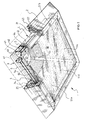
- FIG. 1 a first light box 1 according to the present invention is shown.
- the light box 1 comprises, enclosed in an external frame 2, an optical cavity 3 of a square shape, described in more detail below, and four elongated light sources 4, arranged at each side edge of the square optical cavity 3.
- each light source 4 comprises a parabolic reflector 41 and a fluorescent tube 42 arranged at the focus of the parabolic reflector 41 by means of holders 43, so that the light from the fluorescent tube 42 is directed into the optical cavity 3 essentially parallel to its major faces 5 and 6 (fig. 2).
- parabolic reflector 41 has at its base a portion 44 shaped as a dove-tail. This provision allows, in a per se known manner, to deflect those light rays (essentially horizontal to the left in the view of fig. 2) that would otherwise be reflected back into the fluorescent tube 42, thus increasing the efficiency of light source 4.
- ballast 45 for the light source 4 is also shown in figure 2, while the electrical connections of the light box 1 are omitted from the figures for reasons of clarity.
- the light sources 4 may be of whatever type, as far as both the optical means (parabolic reflector 41) and the electro-optical means (fluorescent tube 42) are concerned.
- a row of LEDs or an arrangement of a single LED and an auxiliary light guide as disclosed in the above cited EP 0 377 309 A2 may be substituted for each light source 4.
- Frame 2 advantageously comprises a supporting inner profile 21 for attachment of the light sources 4 and the major faces 5, 6 of the light guide 1.
- Supporting inner profile 21 also has spaces 22 for insertion of a hanging hook or similar means for attachment of the light box 1 to a ceiling for use as a luminaire, and an external cover 23 that may, as shown in figs. 1 and 2, be inclined so that the frame 2 converges in a direction from the back to the front of the luminaire and gives the latter a pyramid shaped for aesthetical reasons.
- Frame 2 is moreover provided with a bottom flap 24 pivoted to the external cover 23 at hinge 25, so as to allow access to fluorescent tubes 42, electrical wiring and ballast 45 for maintenance and replacement.
- Flap 24 moreover is used to aid in holding in place the first or front major face 5 of the light box.
- the first or front face 5 of the optical cavity 3 comprises a micro-structured transparent material 51 to reflect part of the light from light sources 4 back into the optical cavity 3, and to refract part of the light from light sources 4 so as to be emitted out of the light box 1.
- the micro-structured transparent material 51 of the first major face 5 comprises a plurality of portions (four portions 51a-51d being shown in the embodiment of fig. 1), so arranged that the micro-structures of adjacent portions are not parallel to each other.
- each portion 51a-51d of micro-structured transparent material 51 of the first major face 5 is arranged with its micro-structures essentially perpendicular to an adjacent edge of the light box, i.e. essentially perpendicular to the adjacent elongated light source 4.
- the micro-structured transparent material 51 of the first major face 5 is arranged with the micro-structures facing away from the optical cavity 2, (i.e. towards the bottom in the figures).
- a particularly suited micro-structured transparent material is that commercially available as ScotchTM Optical Lighting Film 2301 from 3M Company.
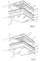
- the portions 51a-51d of micro-structured transparent material 51 are supported by a first sheet 52 of a supporting transparent material, such as a polycarbonate.
- either of the two supporting transparent sheets 52 and 53 may be dispensed with, or even both of them if a self-supporting micro-structured transparent material 51 is used.
- the portions 51a-51d may be adhered to supporting transparent sheet 52 by a transparent adhesive, such as a pressure sensitive adhesive. However, to avoid any adverse effects on the optical performance of the micro-structured transparent material 51, the portions 51a-51d are preferably not attached over their whole surfaces to the supporting transparent sheet 52.
- portions 51a-51d are cut to form a square of a slightly smaller area than the supporting transparent sheets 52 and 53, and the latter are then fixed together (with the portions 51a-51d sandwiched between them) by a peripheral frame of double-sided adhesive tape 54 located between the sheets.
- a particularly suited double-sided adhesive tape 54 is that commercially available as VHBTM Tape from 3M Company.
- Fig. 3 further shows two strips of adhesive tape 55 arranged along the diagonals of front face 5, that is along the adjacent sides of adjacent portions 51a-b, b-c, c-d, d-a of micro-structured transparent material 51.
- such adhesive tape 55 also improves the appearance of the light box 1 by hiding the trimmed edges of each portion 51a-d.
- a particularly suited adhesive tape is that commercially available as AccentrimTM from 3M Company.
- the adjacent portions 51a-b, b-c, c-d, d-a of micro-structured transparent material 51 may be attached to each other on the thickness sides by a transparent adhesive.
- a peripheral frame of suitable optical film 56 may be applied as shown in figs. 1 and 3.
- the optical film may, for example, be the silver dot printed adhesive film available for use as an anti-glare band on car windscreens.
- Optical film 56 may of course be dispensed with, for example by having the pivoting flap 25 of frame 2 extend to a greater degree towards the centre of the light box 1 so as to hide the double-sided adhesive 54.
- a graphics film 57 extends over the whole of the first major face 5.
- a film having a pattern providing a rice paper effect is used, the uniformity of luminosity/illumination of the front face 5 will be further improved, as will the appearance of the light box 1 especially when the light sources 4 are off.
- a particularly suited graphics film 56 is one of the series FasaraTM Glass Decorative Films, commercially available from 3M Company, most preferably the "Sagano" version, product number SH2PT SA.
- the second major face or rear face 6 is designed so as to reflect the light from light sources 4 striking on it back into the optical cavity 3, thus co-operating with the front face 5 in guiding the light within the optical cavity 3.
- the second major or rear face 6 is partly specularly reflective and partly diffusively reflective, so that the angles of the light rays may be partly deviated to a direction allowing them to be emitted from the front face 5.
- the rear face 6 comprises a specularly reflective substrate 61 bearing a plurality of diffusely reflective elements 62, e.g. silk-screen printed white paint dots.
- the diffusely reflective elements 62 comprise, in particular, a plurality of rows of dots parallel to the perimeter of the light guide, that is forming squares, spaced apart by a decreasing distance from the perimeter of the light box 1 towards its center.
- the predetermined configuration of diffusely reflective elements 62 is obtained by applying the principles disclosed in WO 02/23084 .
- back face 6 comprises a sheet of dot printed 3MTM Radiant Mirror Film laminated onto an aluminum sheet.
- front and rear faces 5, 6 as disclosed above form an optical cavity or light guide, whereby light from the light sources 4 is transported along the light box 1 and emitted through its front face 5.
- parabolic reflectors 5 will also act as reflecting sides of the optical cavity 3, by reflecting back within the optical cavity 3 any light rays from one of the other three light sources 4 that failed to exit the light box 1 through the front face 8.
- the arrangement of the elongated light sources 4 at opposite edges of the light box 1, in co-operation with the use of more portions 51a-51d of prismatic transparent material 51, with their micro-structures not parallel to each other, allows the design of the light box 1 to be optimized as to uniformity of luminosity/illumination, as well as to control of glare from a ceiling luminaire.
- FIG. 6 an embodiment wherein the major faces 5, 6 of the light box are rectangular is shown in a diagrammatical view.
- the portions 51e-h of micro-structured transparent material 51 are four equal rectangles each at a corner of the light box 1.
- a light source 4 extends for half of each edge of the light box 1.
- the prismatic micro-structures of adjacent pairs of portions of material 51 are not parallel to each other, and in each portion they are arranged perpendicular to the edge of the light box 1 where a light source 4 is arranged.
- micro-structured transparent material 51 are three equal isosceles triangles, each having a side extending along an edge of the light box 1, where a light source 4 is arranged.
- the prismatic micro-structures of the various portions of material 51 are not parallel to each other, and are arranged perpendicular to the edge of the light box 1, and thus to a light source 4.
- FIG. 8 an embodiment wherein the major faces 5, 6 of the light box are hexagons is shown in a diagrammatical view.
- the portions 511-q of micro-structured transparent material 51 are six equal equilateral triangles, each having a side extending along an edge of the light box 1, where a light source 4 is arranged.
- Light sources 4 have been labeled 41-q after the portion 511-q of micro-structured transparent material they are adjacent to.
- the prismatic micro-structures of adjacent pairs of portions of material 51 are not parallel to each other, and in each portion they are arranged perpendicular to the adjacent edge of the light box 1, and thus to a light source 4.
- Light sources 4m and 4p adjacent to portions 51m and 51p of the micro-structured transparent material 5 are shown in phantom to illustrate that they are optional, insofar as a lesser degree of luminosity/illumination uniformity may be acceptable.
- a light source 4 at each edge of light box 1 the light sources 4 being controlled in groups.
- a first switch (not shown) may control light sources 4m and 4p, while a second switch (not shown) may control light sources 41, 4n, 4o, 4q.
- both switches or the second switch only may be closed to power the respective light sources 4 for lighting purposes, while the first switch only may be closed to power light sources 4m and 4p for safety luminous/lighting purposes.
- the embodiments disclosed above are mere examples of various embodiments of a light source according to the present invention.
- the major faces 5, 6 of the light box may be shaped as a regular polygon of any number of sides.
- the portions of micro-structured transparent material 51 will then be isosceles or equilateral triangles, each having a side extending along an edge of the light box 1.
- a preferred use of the light box 1 according to the invention is as a ceiling luminaire.
- frame 2 shall preferably be a parallelepiped instead of pyramidal.
- a light box 1 may of course be made also as a wall lamp, a desk lamp, a floor lamp, etc. by providing for a suitable support.
- a light box 1 according to the invention may also be used e.g. for luminous purposes only, e.g. for signs, advertisement, and decoration.
- Prototypes of light boxes according to the invention have been prepared and tested.
- the exemplary materials listed above were used for the various components of the front face 5 and of the rear face 6.
- the light boxes so constructed exhibited photometric curves of the type shown in fig. 9, in which the curves 71 and 72 represent luminance in cd/klm along the planes 0/180° and 90/270° respectively. It will be seen that the curves 71 and 72 are essentially equal to one another. Moreover, both curves 71 and 72 are contained within 60° with respect to the vertical, that is the conventional limit angle to avoid glare.
- the isolux diagrams were of the form shown in fig. 10, where each of the areas 81', 82' and 83' represents a different lux value. It will be seen that the different areas are all highly symmetric. In practice, the symmetry will be affected (to a greater or lesser extent) by the light output of any neighbouring light boxes.
- the efficiency of the light boxes was within the range 65-75%.
- the light box 1 according to the present invention may be appropriately employed as a ceiling luminaire without any regard as to where a working site, such as a desk, and especially a computer display, will be located below it, in that a suitable glare-free illumination can be provided within the whole footprint of the light box 1.
Landscapes
- Engineering & Computer Science (AREA)
- General Engineering & Computer Science (AREA)
- Non-Portable Lighting Devices Or Systems Thereof (AREA)
Abstract
A light box (1) is disclosed, comprising an optical cavity (3) and at
least one elongated light source (4), the at least one light source (4)
being arranged to direct light into the optical cavity (3) from an
associated edge thereof, the optical cavity (3) comprising a first major
face (5) comprising a prismatic micro-structured transparent material
(51) to reflect part of the light from the at least one light source (4)
back into the optical cavity (3), and to refract part of the light from
the at least one light source (4) out of the light box (1), and an
opposed reflective second major face to reflect the light from the at
least one light source (4) back into the optical cavity (3),
characterized in that said prismatic micro-structured transparent
material (51) of the first major face comprises at least two portions
(51a-d), the prismatic micro-structures of a first portion being not
parallel to the prismatic micro-structures of a second portion. In such
a way, control of uniformity of luminosity/illumination and glare can be
improved.
Description
- The present invention relates to a light box.
- As used herein, "light box" refers to the assembly of at least one light source, and an essentially flat "hollow light guide" or "optical cavity", that in turn refers to an enclosure whose walls have unique optical properties of internal reflection and transmission so as to allow the light from the light source(s) to travel within the optical cavity itself and, possibly, be emitted along one major face thereof.
- It is known to use such light boxes to provide for luminous and possibly illuminating fixtures, such as for general lighting purposes and for display applications (e.g. for computer displays, signs, advertisement, and decoration).
- As shown i.a. in EP 0 293 182 A2, EP 0 308 828 A2, EP 0 377 309 A2, EP 0 490 279 A1, WO 94/29765, WO 01/71248,
GB 2 310 525 A, and an Application Bulletin entitled "Thin Light Box" issued in March 1990 by Minnesota Mining and Manufacturing Company (St. Paul, Minnesota, USA), a light box comprises more specifically a generally hollow, flat box-shaped structure defining a light guide or optical cavity. An elongated light source is typically arranged at one edge of the box-shaped structure to project light within the optical cavity in a direction essentially parallel to the major surfaces of the box-shaped structure. Due to the optical properties of the walls of the optical cavity, the light is partly guided along the light box, and partly allowed to be emitted from one of the major surfaces -hereinafter called the "front face" or "first major face" of the light box, so that it becomes illuminated, and possibly illuminates the exterior. - The elongated light source typically comprises a fluorescent tube. WO 01/71248 (cited above) teaches to use instead a row of LEDs. Furthermore, EP 0 377 309 A2 (cited above as well) discloses a light box wherein a single LED is arranged at one corner of the light box, and an auxiliary light guide is provided at an adjacent edge of the box-shaped structure. In the latter cases, a virtual elongated light source is provided, traditionally arranged at an edge of the optical cavity.
- In the remainder of the description and in the attached claims, "elongated light source" is used to encompass any of the previous, as well as any other suitable elongated light source.
- Embodiments are also known wherein, in order to increase the size of the light box and the uniformity of luminosity/illumination, two elongated light sources are arranged at opposite edges of the optical cavity, examples being again shown in the above cited prior art.
- Although some light boxes are designed to provide a certain pattern of luminosity/illumination (see e.g. the above cited
GB 2 310 525 A) at the front face, for most applications, such as those cited at the beginning, the luminosity/illumination at the front face should be as uniform as possible. - To this end, a so called extractor is typically employed at what will be referred to hereinafter as the "rear face" or "second major face" of the optical cavity, i.e. the major face opposite the luminous/illuminating front face, whereas an optical film is normally employed at the front face of the optical cavity.
- The extractor at the rear face typically comprises a specially designed diffusely reflective pattern on a specularly reflective background, to provide for suitable angles of the light rays for both propagation within the optical cavity and emission from the front face.
- The optical film at the front face is typically a transparent sheet having a smooth major surface and, on the opposite surface, an array of prismatic micro-structures forming ridges and grooves, hereinafter referred to as "prismatic micro-structured transparent material". The tilted sides of the ridges and the index of refraction of the film material cooperate to reflect those light rays which incidence angle falls within a given range back into the optical cavity, and to refract those light rays which incidence angle falls outside the given range out of the light box, possibly according to preferential directions.
- In all known light boxes disclosed in the above cited prior art documents, a single sheet of micro-structured transparent material is employed at the front face, oriented with the micro-structures extending either parallel or perpendicular to the one or two opposed elongated (physical or virtual) light sources.
- Although a good control of uniformity of luminosity/illumination may be achieved by properly designing the light box, an object of the present invention is to further improve the known light boxes as far as uniformity of luminosity/illumination is concerned.
- A secondary object of the present invention is to provide for a better control of glare from the light box when used as a ceiling luminaire.
- The Applicant has indeed perceived that the arrangement of the elongated light sources at opposite edges of the light box, also in co-operation with the directional nature of the micro-structured transparent material, involves a degree of unevenness in the luminosity/illumination of the front face of a light box.
- This unevenness, in the case of illuminating light boxes such as ceiling-mounted luminaires, also brings about a problem of glare, particularly when the light box is designed to provide a large illumination angle in a selected vertical plane to obtain a large illuminated area or footprint below the luminaire. Since the photometric curve in the other vertical planes, and especially in a vertical plane orthogonal to the selected vertical plane, is less well controlled (due to the directional nature of the micro-structured front face of the light box) and typically differs from the photometric curve in the selected vertical plane, there is a risk of the illumination angle in such other planes unintentionally becoming too large, say above 60° with respect to the vertical.
- The above objects are solved, according to the present invention, by using plural portions of micro-structured transparent material, arranged so that the micro-structures of two adjacent portions are not parallel to each other. In such a way, the light guide may be designed to have photometric curves in at least two planes that are essentially equal to one another, both optimized with respect to the limit angle to avoid glare (about 60° with respect to the vertical).
- In a first aspect thereof, the present invention relates to a light box comprising an optical cavity and at least one elongated light source, the at least one light source being arranged to direct light into the optical cavity from an associated edge thereof, the optical cavity comprising (i) a first major face comprising a prismatic micro-structured transparent material to reflect part of the light from the at least one light source back into the optical cavity, and to refract part of the light from the at least one light source out of the light box, and (ii) an opposed reflective second major face to reflect the light from the at least one light source back into the optical cavity, characterized in that said micro-structured transparent material of the first major face comprises at least two portions, the micro-structures of a first portion being not parallel to the micro-structures of an adjacent second portion.
- In the present description and the attached claims, "reflective" is used in a broad sense to encompass materials that are both diffusely reflective and/or specularly reflective.
- Typically, each of said at least two portions of micro-structured transparent material is arranged with its micro-structures essentially perpendicular to an adjacent edge of the light box.
- Typically said micro-structured transparent material of the first major face is arranged with the micro-structures facing away from the optical cavity.
- A particularly suited micro-structured transparent material is that commercially available as Scotch™ Optical Lighting Film 2301 from 3M Company, St. Paul, Minnesota, U.S.A.
- Furthermore, preferably said micro-structured transparent material of the first major face is supported by at least one sheet of a supporting transparent material, more preferably a polycarbonate.
- More preferably, said micro-structured transparent material of the first major face is sandwiched between two sheets of a supporting transparent material, more preferably a polycarbonate.
- The assembly may be held together by common fastening means, such as screws, adhesive or a peripheral frame of double-sided adhesive tape.
- A particularly suited double-sided adhesive tape is that commercially available as VHB™ Tape from 3M Company.
- The at least two portions of micro-structured transparent material may be attached along adjacent sides by strips of adhesive tape, that will also improve appearance by hiding the trimmed edges of each portion.
- A particularly suited adhesive tape is that commercially available as Accentrim™ from 3M Company.
- As an alternative, the at least two portions of micro-structured transparent material may be attached to each other on the thickness sides by a transparent adhesive.
- In an embodiment of the invention, to improve the appearance of the light box, a peripheral frame of optical film may be used in the first major face, one suitable film being the silver dot printed adhesive film available for use as an anti-glare band on car windscreens.
- In another embodiment, the first major face may further comprise a graphics film facing towards the exterior, preferably a film having a pattern providing a rice paper effect.
- The graphics film will typically be also sandwiched between the two sheets of supporting transparent material. In this case, the peripheral frame of optical film may be omitted.
- Such graphics film may be advantageous to further improve the uniformity of luminosity/illumination of the front face, besides improving the appearance of the light box especially when the light sources are off.
- A particularly suited graphics film is one of the series Fasara™ Glass Decorative Films, commercially available from 3M Company, most preferably the "Sagano" version, product number SH2PT SA.
- Typically, the second major face is partly specularly reflective and partly diffusively reflective, so that the angles of the light rays may be partly deviated to a direction allowing them to be emitted from the first major face.
- Preferably said second major face comprises a specularly reflective substrate bearing a plurality of diffusely reflective elements (for example, white paint dots) in a predetermined configuration.
- More preferably, said diffusely reflective elements are silk-screen printed onto the specularly reflective substrate.
- Most preferably, said predetermined configuration of diffusely reflective elements comprises a plurality of rows of dots parallel to the perimeter of the light box, spaced apart by a decreasing distance from the perimeter of the light box towards its center.
- More particularly, the predetermined configuration of diffusely reflective elements is obtained by applying the principles disclosed in WO 02/23084.
- In a particularly preferred embodiment, the second major face or back face comprises a Radiant Mirror Film™ (commercially available from 3M Company), dot printed and laminated onto an aluminum sheet.
- The major faces of said light box may be of a shape selected from the group comprising square, pentagonal, hexagonal, or of a regular polygon of any number of sides, said at least two portions of micro-structured transparent material being isosceles or equilateral triangles, each having a base extending along an edge of the light box. In other words, the triangles have at least two equal sides.
- In an alternative embodiment, said major faces of said light box are rectangular, said at least two portions of micro-structured transparent material being four equal rectangles each at a corner of the light box.
- Preferably said at least one elongated light source comprises one light source at each edge of the light box, although they may also be less in number than the number of edges of the light box, especially when the latter are many and the uniformity requirements are not very strict.
- According to an advantageous embodiment, said light sources are controlled in at least two groups. This provision allows e.g. to use all or a first set of light sources for lighting purposes, and a second reduced set of light sources for safety luminous/lighting purposes.
- In particular, each of said elongated light sources comprises a parabolic reflector and a fluorescent tube arranged at its focus.
- To increase the efficiency of the light source, the base of the parabolic reflector is typically dove-tail shaped. In such a case, the apex of the dove-tail portion will spread the light rays that would be otherwise reflected back into the light bulb.
- Alternatively, virtual elongated light sources as described above may be employed.
- Said light box preferably further comprises an external frame enclosing said elongated light sources and holding said first and second major faces.
- The external frame may converge in a direction from said second to said first major faces, whereby the light box has a pyramidal shape.
- Said external frame may be provided with means for attachment to a surface, such as means for mounting the light box in, or on, a ceiling for use as a luminaire.
- In a second aspect thereof, the invention relates to use of the light box as disclosed above as a ceiling luminaire, in particular either as an embedded ceiling luminaire or as a overhung ceiling luminaire.
- Features and advantages of the invention shall now be illustrated with reference to embodiments represented by way of non-limitative examples in the attached drawings, wherein:
- fig. 1 shows a perspective and partially broken away view of a light box according to the invention,
- fig. 2 shows a partial section view of the light box of Fig. 1,
- fig. 3 shows a partial exploded view of a first configuration of the first major face of the light box of Fig. 1,
- fig. 4 shows a partial exploded view of a second configuration of a first major face of the light box of Fig. 1,
- fig. 5 shows a plan view of the second major face of the light box of Fig. 1,
- fig. 6 shows a diagrammatic top view of a second light box according to the present invention,
- fig. 7 shows a diagrammatic top view of a third light box according to the present invention,
- fig. 8 shows a diagrammatic top view of a fourth light box according to the present invention,
- fig. 9 shows photometric curves of a light box according to example 1 below, and
- fig. 10 shows an isolux diagram for the light box, according to example 1.
- In figures 1 to 5 a
first light box 1 according to the present invention is shown. - The
light box 1 comprises, enclosed in anexternal frame 2, anoptical cavity 3 of a square shape, described in more detail below, and fourelongated light sources 4, arranged at each side edge of the squareoptical cavity 3. - The
light sources 4 are designed to direct light into theoptical cavity 3 from their respective edge. To this end, eachlight source 4 comprises aparabolic reflector 41 and afluorescent tube 42 arranged at the focus of theparabolic reflector 41 by means ofholders 43, so that the light from thefluorescent tube 42 is directed into theoptical cavity 3 essentially parallel to itsmajor faces 5 and 6 (fig. 2). - As better shown in figure 2,
parabolic reflector 41 has at its base aportion 44 shaped as a dove-tail. This provision allows, in a per se known manner, to deflect those light rays (essentially horizontal to the left in the view of fig. 2) that would otherwise be reflected back into thefluorescent tube 42, thus increasing the efficiency oflight source 4. - A
ballast 45 for thelight source 4 is also shown in figure 2, while the electrical connections of thelight box 1 are omitted from the figures for reasons of clarity. - It will be understood that the
light sources 4 may be of whatever type, as far as both the optical means (parabolic reflector 41) and the electro-optical means (fluorescent tube 42) are concerned. For example, a row of LEDs or an arrangement of a single LED and an auxiliary light guide as disclosed in the above cited EP 0 377 309 A2 may be substituted for eachlight source 4. -
Frame 2 advantageously comprises a supportinginner profile 21 for attachment of thelight sources 4 and themajor faces light guide 1. - Supporting
inner profile 21 also hasspaces 22 for insertion of a hanging hook or similar means for attachment of thelight box 1 to a ceiling for use as a luminaire, and anexternal cover 23 that may, as shown in figs. 1 and 2, be inclined so that theframe 2 converges in a direction from the back to the front of the luminaire and gives the latter a pyramid shaped for aesthetical reasons. -
Frame 2 according to the present embodiment is moreover provided with abottom flap 24 pivoted to theexternal cover 23 athinge 25, so as to allow access tofluorescent tubes 42, electrical wiring andballast 45 for maintenance and replacement. -
Flap 24 moreover is used to aid in holding in place the first or frontmajor face 5 of the light box. - With further reference to fig. 3, the first or
front face 5 of theoptical cavity 3 comprises a micro-structuredtransparent material 51 to reflect part of the light fromlight sources 4 back into theoptical cavity 3, and to refract part of the light fromlight sources 4 so as to be emitted out of thelight box 1. - According to the invention, the micro-structured
transparent material 51 of the firstmajor face 5 comprises a plurality of portions (fourportions 51a-51d being shown in the embodiment of fig. 1), so arranged that the micro-structures of adjacent portions are not parallel to each other. - More particularly, each
portion 51a-51d of micro-structuredtransparent material 51 of the firstmajor face 5 is arranged with its micro-structures essentially perpendicular to an adjacent edge of the light box, i.e. essentially perpendicular to the adjacent elongatedlight source 4. - In a per se known manner, the micro-structured
transparent material 51 of the firstmajor face 5 is arranged with the micro-structures facing away from theoptical cavity 2, (i.e. towards the bottom in the figures). - A particularly suited micro-structured transparent material is that commercially available as Scotch™ Optical Lighting Film 2301 from 3M Company.
- The
portions 51a-51d of micro-structuredtransparent material 51 are supported by afirst sheet 52 of a supporting transparent material, such as a polycarbonate. - A
second sheet 53 of supporting transparent material, such as a polycarbonate, is also shown on the other side of micro-structuredtransparent material 51, which is thus sandwiched between supportingtransparent sheets - It will be understood that either of the two supporting
transparent sheets transparent material 51 is used. - The
portions 51a-51d may be adhered to supportingtransparent sheet 52 by a transparent adhesive, such as a pressure sensitive adhesive. However, to avoid any adverse effects on the optical performance of the micro-structuredtransparent material 51, theportions 51a-51d are preferably not attached over their whole surfaces to the supportingtransparent sheet 52. - Alternatively,
portions 51a-51d are cut to form a square of a slightly smaller area than the supportingtransparent sheets portions 51a-51d sandwiched between them) by a peripheral frame of double-sidedadhesive tape 54 located between the sheets. - A particularly suited double-sided
adhesive tape 54 is that commercially available as VHB™ Tape from 3M Company. - Fig. 3 further shows two strips of
adhesive tape 55 arranged along the diagonals offront face 5, that is along the adjacent sides ofadjacent portions 51a-b, b-c, c-d, d-a of micro-structuredtransparent material 51. - Besides aiding in holding together the
various portions 51a-d, suchadhesive tape 55 also improves the appearance of thelight box 1 by hiding the trimmed edges of eachportion 51a-d. - A particularly suited adhesive tape is that commercially available as Accentrim™ from 3M Company.
- As an alternative, the
adjacent portions 51a-b, b-c, c-d, d-a of micro-structuredtransparent material 51 may be attached to each other on the thickness sides by a transparent adhesive. - Finally, again to improve the appearance of the light box, a peripheral frame of suitable
optical film 56 may be applied as shown in figs. 1 and 3. The optical film may, for example, be the silver dot printed adhesive film available for use as an anti-glare band on car windscreens. -
Optical film 56 may of course be dispensed with, for example by having the pivotingflap 25 offrame 2 extend to a greater degree towards the centre of thelight box 1 so as to hide the double-sided adhesive 54. - As a further alternative, in the embodiment of fig. 4, a
graphics film 57 extends over the whole of the firstmajor face 5. When for example a film having a pattern providing a rice paper effect is used, the uniformity of luminosity/illumination of thefront face 5 will be further improved, as will the appearance of thelight box 1 especially when thelight sources 4 are off. - A particularly
suited graphics film 56 is one of the series Fasara™ Glass Decorative Films, commercially available from 3M Company, most preferably the "Sagano" version, product number SH2PT SA. - As far as the second major face or
rear face 6 is concerned, it is designed so as to reflect the light fromlight sources 4 striking on it back into theoptical cavity 3, thus co-operating with thefront face 5 in guiding the light within theoptical cavity 3. - More precisely, in a per se known manner, the second major or
rear face 6 is partly specularly reflective and partly diffusively reflective, so that the angles of the light rays may be partly deviated to a direction allowing them to be emitted from thefront face 5. - In the embodiment of figs. 1 and 5, the
rear face 6 comprises a specularlyreflective substrate 61 bearing a plurality of diffuselyreflective elements 62, e.g. silk-screen printed white paint dots. - The diffusely
reflective elements 62 comprise, in particular, a plurality of rows of dots parallel to the perimeter of the light guide, that is forming squares, spaced apart by a decreasing distance from the perimeter of thelight box 1 towards its center. - More particularly, the predetermined configuration of diffusely
reflective elements 62 is obtained by applying the principles disclosed in WO 02/23084. - In a particularly preferred embodiment, back
face 6 comprises a sheet of dot printed 3M™ Radiant Mirror Film laminated onto an aluminum sheet. - It will be appreciated by those skilled in the art that the front and
rear faces light sources 4 is transported along thelight box 1 and emitted through itsfront face 5. It will further be understood that theparabolic reflectors 5 will also act as reflecting sides of theoptical cavity 3, by reflecting back within theoptical cavity 3 any light rays from one of the other threelight sources 4 that failed to exit thelight box 1 through the front face 8. - As will be better seen with reference to the examples below, the arrangement of the
elongated light sources 4 at opposite edges of thelight box 1, in co-operation with the use ofmore portions 51a-51d of prismatictransparent material 51, with their micro-structures not parallel to each other, allows the design of thelight box 1 to be optimized as to uniformity of luminosity/illumination, as well as to control of glare from a ceiling luminaire. - In fig. 6, an embodiment wherein the
major faces portions 51e-h of micro-structuredtransparent material 51 are four equal rectangles each at a corner of thelight box 1. Alight source 4 extends for half of each edge of thelight box 1. Again, the prismatic micro-structures of adjacent pairs of portions ofmaterial 51 are not parallel to each other, and in each portion they are arranged perpendicular to the edge of thelight box 1 where alight source 4 is arranged. - In fig. 7, an embodiment wherein the
major faces transparent material 51 are three equal isosceles triangles, each having a side extending along an edge of thelight box 1, where alight source 4 is arranged. Again, the prismatic micro-structures of the various portions ofmaterial 51 are not parallel to each other, and are arranged perpendicular to the edge of thelight box 1, and thus to alight source 4. - In fig. 8, an embodiment wherein the
major faces transparent material 51 are six equal equilateral triangles, each having a side extending along an edge of thelight box 1, where alight source 4 is arranged.Light sources 4 have been labeled 41-q after the portion 511-q of micro-structured transparent material they are adjacent to. Again, the prismatic micro-structures of adjacent pairs of portions ofmaterial 51 are not parallel to each other, and in each portion they are arranged perpendicular to the adjacent edge of thelight box 1, and thus to alight source 4. -
Light sources 4m and 4p adjacent toportions 51m and 51p of the micro-structuredtransparent material 5 are shown in phantom to illustrate that they are optional, insofar as a lesser degree of luminosity/illumination uniformity may be acceptable. - According to an advantageous embodiment, however, there will be a
light source 4 at each edge oflight box 1, thelight sources 4 being controlled in groups. For example, a first switch (not shown) may controllight sources 4m and 4p, while a second switch (not shown) may controllight sources 41, 4n, 4o, 4q. Thus, both switches or the second switch only may be closed to power therespective light sources 4 for lighting purposes, while the first switch only may be closed to powerlight sources 4m and 4p for safety luminous/lighting purposes. - It will be easily understood that the embodiments disclosed above are mere examples of various embodiments of a light source according to the present invention. Indeed, the
major faces transparent material 51 will then be isosceles or equilateral triangles, each having a side extending along an edge of thelight box 1. - A preferred use of the
light box 1 according to the invention is as a ceiling luminaire. - In case the luminaire is to be embedded into the ceiling of a room,
frame 2 shall preferably be a parallelepiped instead of pyramidal. - For illuminating purposes, a
light box 1 according to the invention may of course be made also as a wall lamp, a desk lamp, a floor lamp, etc. by providing for a suitable support. - Moreover, a
light box 1 according to the invention may also be used e.g. for luminous purposes only, e.g. for signs, advertisement, and decoration. - Prototypes of light boxes according to the invention have been prepared and tested. In the prototypes, the exemplary materials listed above were used for the various components of the
front face 5 and of therear face 6. - The light boxes so constructed exhibited photometric curves of the type shown in fig. 9, in which the
curves 71 and 72 represent luminance in cd/klm along the planes 0/180° and 90/270° respectively. It will be seen that thecurves 71 and 72 are essentially equal to one another. Moreover, bothcurves 71 and 72 are contained within 60° with respect to the vertical, that is the conventional limit angle to avoid glare. - The isolux diagrams were of the form shown in fig. 10, where each of the areas 81', 82' and 83' represents a different lux value. It will be seen that the different areas are all highly symmetric. In practice, the symmetry will be affected (to a greater or lesser extent) by the light output of any neighbouring light boxes.
- The efficiency of the light boxes was within the range 65-75%.
- The above characteristics demonstrate that the
light box 1 according to the present invention may be appropriately employed as a ceiling luminaire without any regard as to where a working site, such as a desk, and especially a computer display, will be located below it, in that a suitable glare-free illumination can be provided within the whole footprint of thelight box 1.
Claims (24)
- Light box (1) comprising an optical cavity (3) and at least one elongated light source (4), the at least one light source (4) being arranged to direct light into the optical cavity (3) from an associated edge thereof, the optical cavity (3) comprising (i) a first major face (5) comprising a prismatic micro-structured transparent material (51) to reflect part of the light from the at least one light source (4) back into the optical cavity (3), and to refract part of the light from the at least one light source (4) out of the light box (1), and (ii) an opposed reflective second major face (6) to reflect the light from the at least one light source (4) back into the optical cavity (3), characterized in that said micro-structured transparent material (51) of the first major face (5) comprises at least two portions (51a-q), so arranged that the prismatic micro-structures of a first portion are not parallel to the prismatic micro-structures of an adjacent second portion.
- Light box (1) according to claim 1, characterized in that each of said at least two portions (51a-q) of micro-structured transparent material (51) is arranged with its prismatic micro-structures essentially perpendicular to an adjacent edge of the light box.
- Light box (1) according to claim 1 or 2, characterized in that said micro-structured transparent material (51) of the first major face (5) is arranged with the micro-structures facing away from the optical cavity (3).
- Light box (1) according to any of the previous claims, characterized in that said micro-structured transparent material (51) of the first major face (5) is supported by at least one sheet (52, 53) of a supporting transparent material.
- Light box (1) according to claim 4, characterized in that the assembly of micro-structured transparent material (51) and at least one sheet (52, 53) of a supporting transparent material is held together by a peripheral double-sided adhesive tape (54).
- Light box (1) according to any of the previous claims, characterized in that the at least two portions (51a-q) of micro-structured transparent material (51) are attached to each other along adjacent sides by strips of adhesive tape (55).
- Light box (1) according to any of the previous claims, characterized in that the first major face (5) further comprises a peripheral frame of optical film (56).
- Light box (1) according to any of claims 1-6, characterized in that the first major face (5) further comprises an optical film (57) facing towards the exterior.
- Light box (1) according to any of the previous claims, characterized in that the second major face (6) is partly specularly reflective and partly diffusively reflective.
- Light box (1) according to claim 9, characterized in that said second major face (6) comprises a specularly reflective substrate (61) bearing a plurality of diffusely reflective elements (62) in a predetermined configuration.
- Light box (1) according to claim 10, characterized in that said diffusely reflective elements (62) are silk-screen printed onto the specularly reflective substrate (61).
- Light box (1) according to any of claims 10-11, characterized in that said predetermined configuration of diffusely reflective elements (62) comprises a plurality of rows of dots parallel to the perimeter of the light box (1), spaced apart by a decreasing distance from the perimeter of the light box (1) towards its center.
- Light box (1) according to any of the previous claims, characterized in that said major faces (5, 6) of said light box (1) have the shape of a regular polygon, said at least two portions (51a-d, 51i-q) of micro-structured transparent material (51) being isosceles or equilateral triangles, each having a base extending along an edge of the light box (1) .
- Light box (1) according to any of the claims 1-12, characterized in that said major faces (5, 6) of said light guide are rectangular, said at least two portions (51e-h) of micro-structured transparent material (51) being four equal rectangles each at a corner of the light box (1).
- Light box (1) according to any of the previous claims, characterized in that said at least one elongated light source (4) comprises one light source (4) at each edge of the light box.
- Light box (1) according to claim 15, characterized in that said light sources (4) are controlled in at least two groups.
- Light box (1) according to any of the previous claims, characterized in that each of said elongated light sources (4) comprises a parabolic reflector (41) and a fluorescent tube (42) arranged at its focus.
- Light box (1) according to claim 17, characterized in that the base (44) of the parabolic reflector (41) is typically dove-tail shaped.
- Light box (1) according to any of the previous claims, characterized in that it further comprises an external frame (2) enclosing said elongated light sources (4) and holding said first and second major faces (5, 6).
- Light box (1) according to claim 19, characterized in that the external frame (2) converges in a direction from said second major face (6) to said first major face (5).
- Light box (1) according to any of the claims 19-20, characterized in that said external frame (2) is provided with means for attachment to a surface.
- Use of the light box (1) as claimed in any of claims 1-21 as a ceiling luminaire.
- Use according to claim 22 as an embedded ceiling luminaire.
- Use according to claim 22 as a overhung ceiling luminaire.
Priority Applications (3)
| Application Number | Priority Date | Filing Date | Title |
|---|---|---|---|
| EP04076121A EP1586813A1 (en) | 2004-04-16 | 2004-04-16 | Light box |
| PCT/US2005/008573 WO2005106321A1 (en) | 2004-04-16 | 2005-03-14 | Light box |
| EP05729222A EP1740880A1 (en) | 2004-04-16 | 2005-03-14 | Light box |
Applications Claiming Priority (1)
| Application Number | Priority Date | Filing Date | Title |
|---|---|---|---|
| EP04076121A EP1586813A1 (en) | 2004-04-16 | 2004-04-16 | Light box |
Publications (1)
| Publication Number | Publication Date |
|---|---|
| EP1586813A1 true EP1586813A1 (en) | 2005-10-19 |
Family
ID=34928149
Family Applications (2)
| Application Number | Title | Priority Date | Filing Date |
|---|---|---|---|
| EP04076121A Withdrawn EP1586813A1 (en) | 2004-04-16 | 2004-04-16 | Light box |
| EP05729222A Withdrawn EP1740880A1 (en) | 2004-04-16 | 2005-03-14 | Light box |
Family Applications After (1)
| Application Number | Title | Priority Date | Filing Date |
|---|---|---|---|
| EP05729222A Withdrawn EP1740880A1 (en) | 2004-04-16 | 2005-03-14 | Light box |
Country Status (2)
| Country | Link |
|---|---|
| EP (2) | EP1586813A1 (en) |
| WO (1) | WO2005106321A1 (en) |
Cited By (10)
| Publication number | Priority date | Publication date | Assignee | Title |
|---|---|---|---|---|
| EP1681508A3 (en) * | 2005-01-12 | 2006-09-20 | Manfred Grimm | Recessed ceiling lighting fixture |
| WO2011039272A1 (en) * | 2009-09-29 | 2011-04-07 | Zumtobel Lighting Gmbh | Lighting assembly comprising a light-influencing element |
| EP2312205A1 (en) * | 2009-10-16 | 2011-04-20 | RIDI Leuchten GmbH | Lamp |
| WO2012056352A1 (en) * | 2010-10-28 | 2012-05-03 | Koninklijke Philips Electronics N.V. | Illumination device, luminaire and lighting system |
| WO2013034152A1 (en) * | 2011-09-09 | 2013-03-14 | Herbert Waldmann Gmbh & Co. Kg | Light with a film for altering the radiation characteristics |
| CN104728687A (en) * | 2013-12-24 | 2015-06-24 | 深圳市海洋王照明工程有限公司 | Lamp |
| US9383075B2 (en) | 2011-02-22 | 2016-07-05 | Koninklijke Philips N.V. | Collimator comprising a prismatic layer stack, and lighting unit comprising such a collimator |
| US9632326B2 (en) | 2010-10-28 | 2017-04-25 | Philips Lighting Holding B.V. | Collimator comprising a prismatic layer stack, and lighting unit comprising such collimator |
| EP2844908B1 (en) * | 2012-04-30 | 2018-03-07 | SnapTrack, Inc. | Multi-beam light engine |
| WO2018081182A1 (en) * | 2016-10-24 | 2018-05-03 | Ameritech Llc | Luminaire including light emitting diodes and having improved energy-efficiency |
Citations (13)
| Publication number | Priority date | Publication date | Assignee | Title |
|---|---|---|---|---|
| FR722673A (en) * | 1931-09-05 | 1932-03-23 | Holophane Sa | Lighting apparatus using rectilinear light sources |
| US2050429A (en) * | 1932-07-01 | 1936-08-11 | Holophane Co Inc | Light mixing apparatus |
| US3209137A (en) * | 1963-04-29 | 1965-09-28 | K S H Plastics Inc | Luminous ceiling |
| US4462068A (en) * | 1982-06-24 | 1984-07-24 | Manville Service Corporation | Luminaire with improved lens structure |
| EP0293182A2 (en) | 1987-05-26 | 1988-11-30 | Minnesota Mining And Manufacturing Company | Light fixture providing normalized output |
| EP0308828A2 (en) | 1987-09-19 | 1989-03-29 | Canon Kabushiki Kaisha | Illuminator and display panel employing it |
| EP0377309A2 (en) | 1989-01-03 | 1990-07-11 | Minnesota Mining And Manufacturing Company | Back-lit display |
| EP0490279A2 (en) | 1990-12-08 | 1992-06-17 | Minnesota Mining And Manufacturing Company | Light box |
| WO1994029765A1 (en) | 1993-06-08 | 1994-12-22 | Minnesota Mining And Manufacturing Company | Liquid crystal display with enhanced brightness |
| US5530628A (en) * | 1993-04-05 | 1996-06-25 | Peerless Lighting Corporation | Task light |
| GB2310525A (en) | 1996-02-24 | 1997-08-27 | Ronnie Revell | Illuminated display device |
| WO2001071248A1 (en) | 2000-03-16 | 2001-09-27 | 3M Innovative Properties Company | Light guides suitable for illuminated displays |
| WO2002023084A1 (en) | 2000-09-15 | 2002-03-21 | 3M Innovative Properties Company | Light extractor for a light guide lamp |
Family Cites Families (1)
| Publication number | Priority date | Publication date | Assignee | Title |
|---|---|---|---|---|
| JP3362900B2 (en) * | 1993-03-09 | 2003-01-07 | 富士通株式会社 | Surface emitting device |
-
2004
- 2004-04-16 EP EP04076121A patent/EP1586813A1/en not_active Withdrawn
-
2005
- 2005-03-14 EP EP05729222A patent/EP1740880A1/en not_active Withdrawn
- 2005-03-14 WO PCT/US2005/008573 patent/WO2005106321A1/en not_active Ceased
Patent Citations (13)
| Publication number | Priority date | Publication date | Assignee | Title |
|---|---|---|---|---|
| FR722673A (en) * | 1931-09-05 | 1932-03-23 | Holophane Sa | Lighting apparatus using rectilinear light sources |
| US2050429A (en) * | 1932-07-01 | 1936-08-11 | Holophane Co Inc | Light mixing apparatus |
| US3209137A (en) * | 1963-04-29 | 1965-09-28 | K S H Plastics Inc | Luminous ceiling |
| US4462068A (en) * | 1982-06-24 | 1984-07-24 | Manville Service Corporation | Luminaire with improved lens structure |
| EP0293182A2 (en) | 1987-05-26 | 1988-11-30 | Minnesota Mining And Manufacturing Company | Light fixture providing normalized output |
| EP0308828A2 (en) | 1987-09-19 | 1989-03-29 | Canon Kabushiki Kaisha | Illuminator and display panel employing it |
| EP0377309A2 (en) | 1989-01-03 | 1990-07-11 | Minnesota Mining And Manufacturing Company | Back-lit display |
| EP0490279A2 (en) | 1990-12-08 | 1992-06-17 | Minnesota Mining And Manufacturing Company | Light box |
| US5530628A (en) * | 1993-04-05 | 1996-06-25 | Peerless Lighting Corporation | Task light |
| WO1994029765A1 (en) | 1993-06-08 | 1994-12-22 | Minnesota Mining And Manufacturing Company | Liquid crystal display with enhanced brightness |
| GB2310525A (en) | 1996-02-24 | 1997-08-27 | Ronnie Revell | Illuminated display device |
| WO2001071248A1 (en) | 2000-03-16 | 2001-09-27 | 3M Innovative Properties Company | Light guides suitable for illuminated displays |
| WO2002023084A1 (en) | 2000-09-15 | 2002-03-21 | 3M Innovative Properties Company | Light extractor for a light guide lamp |
Non-Patent Citations (1)
| Title |
|---|
| Thin Light Box by Minnesota Mining and Manufacturing Company, March 1990 (St.Paul Minnesota, USA) |
Cited By (18)
| Publication number | Priority date | Publication date | Assignee | Title |
|---|---|---|---|---|
| EP1681508A3 (en) * | 2005-01-12 | 2006-09-20 | Manfred Grimm | Recessed ceiling lighting fixture |
| WO2011039272A1 (en) * | 2009-09-29 | 2011-04-07 | Zumtobel Lighting Gmbh | Lighting assembly comprising a light-influencing element |
| EP2312205A1 (en) * | 2009-10-16 | 2011-04-20 | RIDI Leuchten GmbH | Lamp |
| WO2012056352A1 (en) * | 2010-10-28 | 2012-05-03 | Koninklijke Philips Electronics N.V. | Illumination device, luminaire and lighting system |
| CN103154782A (en) * | 2010-10-28 | 2013-06-12 | 皇家飞利浦电子股份有限公司 | Illumination device, luminaire and lighting system |
| US9632326B2 (en) | 2010-10-28 | 2017-04-25 | Philips Lighting Holding B.V. | Collimator comprising a prismatic layer stack, and lighting unit comprising such collimator |
| RU2606946C2 (en) * | 2010-10-28 | 2017-01-10 | Филипс Лайтинг Холдинг Б.В. | Illumination device, luminaire and lighting system |
| CN103154782B (en) * | 2010-10-28 | 2015-09-30 | 皇家飞利浦电子股份有限公司 | Illumination apparatus, luminaire and illuminator |
| US9279568B2 (en) | 2010-10-28 | 2016-03-08 | Koninklijke Philips N.V. | Illumination device, luminaire and lighting system |
| US9383075B2 (en) | 2011-02-22 | 2016-07-05 | Koninklijke Philips N.V. | Collimator comprising a prismatic layer stack, and lighting unit comprising such a collimator |
| WO2013034152A1 (en) * | 2011-09-09 | 2013-03-14 | Herbert Waldmann Gmbh & Co. Kg | Light with a film for altering the radiation characteristics |
| CN103782089B (en) * | 2011-09-09 | 2017-02-15 | 赫伯特沃尔德曼两合公司 | Light with a film for altering the radiation characteristics |
| CN103782089A (en) * | 2011-09-09 | 2014-05-07 | 赫伯特沃尔德曼两合公司 | Light with a film for altering the radiation characteristics |
| US9746169B2 (en) | 2011-09-09 | 2017-08-29 | Herbert Waldmann Gmbh & Co. Kg | Light with a film for altering the radiation characteristics |
| EP2844908B1 (en) * | 2012-04-30 | 2018-03-07 | SnapTrack, Inc. | Multi-beam light engine |
| CN104728687A (en) * | 2013-12-24 | 2015-06-24 | 深圳市海洋王照明工程有限公司 | Lamp |
| CN104728687B (en) * | 2013-12-24 | 2019-02-05 | 深圳市海洋王照明工程有限公司 | Lamps and lanterns |
| WO2018081182A1 (en) * | 2016-10-24 | 2018-05-03 | Ameritech Llc | Luminaire including light emitting diodes and having improved energy-efficiency |
Also Published As
| Publication number | Publication date |
|---|---|
| EP1740880A1 (en) | 2007-01-10 |
| WO2005106321A1 (en) | 2005-11-10 |
Similar Documents
| Publication | Publication Date | Title |
|---|---|---|
| US8419236B2 (en) | Light boxes with uniform light distribution | |
| US5542201A (en) | Indirectly illuminated sign | |
| US6308444B1 (en) | Light illuminated display board and lampshade using light refraction and reflection effect of transparent acrylic plastic plates | |
| EP1843084B1 (en) | Semi-recessed luminaire | |
| US20130201690A1 (en) | Illumination device and luminaire | |
| RU2608079C2 (en) | Lighting fixture with light plate | |
| US9297506B2 (en) | LED-based light fixture | |
| US20130182458A1 (en) | Light-emitting device for emitting diffuse light | |
| CN1321335C (en) | Evenly illuminated double-sided lighting panel | |
| CN105706156B (en) | Lighting apparatus | |
| EP1586813A1 (en) | Light box | |
| US10774529B2 (en) | Ceiling tile with integrated lighting and ceiling system | |
| US7077536B2 (en) | Double-sided edge lighting-type display light box | |
| CA2474334A1 (en) | Lamps | |
| JPH0514361B2 (en) | ||
| CN103154782A (en) | Illumination device, luminaire and lighting system | |
| JP2004302028A (en) | Display device and guide light device | |
| CN1739426A (en) | Illuminating device of showcase for cultural heritage exhibition | |
| CN220707151U (en) | Anti-dazzle microprism board and lamp with same | |
| JP3391483B2 (en) | light box | |
| KR100984191B1 (en) | Sectional transparent arcylic panel and light emitting diode illumination signboard using the same | |
| DK171286B1 (en) | Advertising, information or display panel - has one or more display surfaces covered with light permeable and=or light-reflecting foil coating | |
| EP1585088A1 (en) | Indirectly illuminated sign | |
| JP2008140000A (en) | Vending machine lighting device and vending machine using the same |
Legal Events
| Date | Code | Title | Description |
|---|---|---|---|
| PUAI | Public reference made under article 153(3) epc to a published international application that has entered the european phase |
Free format text: ORIGINAL CODE: 0009012 |
|
| AK | Designated contracting states |
Kind code of ref document: A1 Designated state(s): AT BE BG CH CY CZ DE DK EE ES FI FR GB GR HU IE IT LI LU MC NL PL PT RO SE SI SK TR |
|
| AX | Request for extension of the european patent |
Extension state: AL HR LT LV MK |
|
| STAA | Information on the status of an ep patent application or granted ep patent |
Free format text: STATUS: THE APPLICATION IS DEEMED TO BE WITHDRAWN |
|
| 18D | Application deemed to be withdrawn |
Effective date: 20051118 |