EP1586760A2 - Fuel injection system for a combustion engine and method of operation - Google Patents
Fuel injection system for a combustion engine and method of operation Download PDFInfo
- Publication number
- EP1586760A2 EP1586760A2 EP05101304A EP05101304A EP1586760A2 EP 1586760 A2 EP1586760 A2 EP 1586760A2 EP 05101304 A EP05101304 A EP 05101304A EP 05101304 A EP05101304 A EP 05101304A EP 1586760 A2 EP1586760 A2 EP 1586760A2
- Authority
- EP
- European Patent Office
- Prior art keywords
- injection
- piezoelectric element
- charging
- beginning
- piezoelectric
- Prior art date
- Legal status (The legal status is an assumption and is not a legal conclusion. Google has not performed a legal analysis and makes no representation as to the accuracy of the status listed.)
- Withdrawn
Links
- 238000002347 injection Methods 0.000 title claims abstract description 91
- 239000007924 injection Substances 0.000 title claims abstract description 91
- 238000000034 method Methods 0.000 title claims abstract description 29
- 239000000446 fuel Substances 0.000 title claims abstract description 23
- 238000002485 combustion reaction Methods 0.000 title claims abstract description 10
- 238000007599 discharging Methods 0.000 claims abstract description 25
- 238000004904 shortening Methods 0.000 claims abstract description 21
- 238000012544 monitoring process Methods 0.000 claims abstract description 3
- 238000012937 correction Methods 0.000 claims description 15
- 238000006073 displacement reaction Methods 0.000 claims description 6
- 230000001419 dependent effect Effects 0.000 claims description 2
- 230000008569 process Effects 0.000 description 15
- 239000003990 capacitor Substances 0.000 description 9
- 238000005259 measurement Methods 0.000 description 7
- 230000008929 regeneration Effects 0.000 description 5
- 238000011069 regeneration method Methods 0.000 description 5
- 230000004913 activation Effects 0.000 description 4
- 230000007423 decrease Effects 0.000 description 4
- 239000002245 particle Substances 0.000 description 4
- 230000009467 reduction Effects 0.000 description 3
- 239000007789 gas Substances 0.000 description 2
- 230000003993 interaction Effects 0.000 description 2
- 230000003071 parasitic effect Effects 0.000 description 2
- 230000002411 adverse Effects 0.000 description 1
- 238000006243 chemical reaction Methods 0.000 description 1
- 125000004122 cyclic group Chemical group 0.000 description 1
- 230000006866 deterioration Effects 0.000 description 1
- 230000000694 effects Effects 0.000 description 1
- 238000005516 engineering process Methods 0.000 description 1
- 230000006870 function Effects 0.000 description 1
- 238000007689 inspection Methods 0.000 description 1
- 238000000926 separation method Methods 0.000 description 1
- 230000009885 systemic effect Effects 0.000 description 1
- 238000012546 transfer Methods 0.000 description 1
- 239000002912 waste gas Substances 0.000 description 1
Images


Classifications
-
- F—MECHANICAL ENGINEERING; LIGHTING; HEATING; WEAPONS; BLASTING
- F02—COMBUSTION ENGINES; HOT-GAS OR COMBUSTION-PRODUCT ENGINE PLANTS
- F02D—CONTROLLING COMBUSTION ENGINES
- F02D41/00—Electrical control of supply of combustible mixture or its constituents
- F02D41/20—Output circuits, e.g. for controlling currents in command coils
- F02D41/2096—Output circuits, e.g. for controlling currents in command coils for controlling piezoelectric injectors
-
- F—MECHANICAL ENGINEERING; LIGHTING; HEATING; WEAPONS; BLASTING
- F02—COMBUSTION ENGINES; HOT-GAS OR COMBUSTION-PRODUCT ENGINE PLANTS
- F02D—CONTROLLING COMBUSTION ENGINES
- F02D41/00—Electrical control of supply of combustible mixture or its constituents
- F02D41/30—Controlling fuel injection
- F02D41/32—Controlling fuel injection of the low pressure type
- F02D41/36—Controlling fuel injection of the low pressure type with means for controlling distribution
-
- F—MECHANICAL ENGINEERING; LIGHTING; HEATING; WEAPONS; BLASTING
- F02—COMBUSTION ENGINES; HOT-GAS OR COMBUSTION-PRODUCT ENGINE PLANTS
- F02D—CONTROLLING COMBUSTION ENGINES
- F02D41/00—Electrical control of supply of combustible mixture or its constituents
- F02D41/30—Controlling fuel injection
- F02D41/38—Controlling fuel injection of the high pressure type
- F02D41/40—Controlling fuel injection of the high pressure type with means for controlling injection timing or duration
- F02D41/402—Multiple injections
- F02D41/405—Multiple injections with post injections
-
- F—MECHANICAL ENGINEERING; LIGHTING; HEATING; WEAPONS; BLASTING
- F02—COMBUSTION ENGINES; HOT-GAS OR COMBUSTION-PRODUCT ENGINE PLANTS
- F02D—CONTROLLING COMBUSTION ENGINES
- F02D41/00—Electrical control of supply of combustible mixture or its constituents
- F02D41/20—Output circuits, e.g. for controlling currents in command coils
- F02D2041/2068—Output circuits, e.g. for controlling currents in command coils characterised by the circuit design or special circuit elements
- F02D2041/2082—Output circuits, e.g. for controlling currents in command coils characterised by the circuit design or special circuit elements the circuit being adapted to distribute current between different actuators or recuperate energy from actuators
-
- Y—GENERAL TAGGING OF NEW TECHNOLOGICAL DEVELOPMENTS; GENERAL TAGGING OF CROSS-SECTIONAL TECHNOLOGIES SPANNING OVER SEVERAL SECTIONS OF THE IPC; TECHNICAL SUBJECTS COVERED BY FORMER USPC CROSS-REFERENCE ART COLLECTIONS [XRACs] AND DIGESTS
- Y02—TECHNOLOGIES OR APPLICATIONS FOR MITIGATION OR ADAPTATION AGAINST CLIMATE CHANGE
- Y02T—CLIMATE CHANGE MITIGATION TECHNOLOGIES RELATED TO TRANSPORTATION
- Y02T10/00—Road transport of goods or passengers
- Y02T10/10—Internal combustion engine [ICE] based vehicles
- Y02T10/40—Engine management systems
Definitions
- the invention relates to a fuel injection system for an internal combustion engine, in particular a diesel engine, with at least two cylinders, the fuel injection system at least two piezoelectric elements and each cylinder at least a piezoelectric element for injecting fuel into the cylinder Charging or discharging is associated with the piezoelectric element, wherein the piezoelectric Elements a single supply unit for charging or discharging the associated with piezoelectric element, wherein the fuel injection system further comprises a Injection control for monitoring a possible overlap of a time interval, in which a piezoelectric element is to be loaded or unloaded, with a time interval, in which the other piezoelectric element is to be loaded or unloaded and wherein in the event of an overlap, the injection control the injection shortened so far that one piezoelectric element is not charged, if the other piezoelectric element to be loaded or unloaded.
- the invention further relates to a Method for operating such a fuel injection system for an internal combustion engine.
- Such a fuel injection system and a method for operating such Fuel injection system are known for example from DE 100 33 343 A1.
- injection systems are used, for example, in diesel vehicles with common-rail technology for use.
- a known field of application are internal combustion engines with a so-called limited two-bank operation.
- two Piezoelectric elements or piezo actuators loaded on different banks simultaneously be, but not simultaneously loaded or unloaded.
- six cylinders results in a range of only 120 ° crankshaft, the is fully usable for injections.
- the invention is therefore based on the object, a fuel injection system and a Process for operating such a further develop that the above Disadvantages are eliminated and a quantity compensation even with shortening of injections over longer periods is possible.
- This object is achieved in a fuel injection system for an internal combustion engine and in a method for operating such according to the invention solved in that to compensate for the shortage of starting gas injected due to the shortening a subsequent injection of the same type by the injection control within predetermined limits is postponed.
- the beginning of an injection of the same type at a later load cycle can thereby be moved sooner or later.
- the shift takes place at an earlier point in time.
- the shifted start of injection can be determined in different ways become.
- the displacement the injection start takes place by means of a correction angle, which is based on one of is limited to an operating point dependent value.
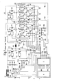
- Fig. 1 shows piezoelectric elements 10, 20, 30, 40, 50, 60 and means for their control.
- A denotes an area in detailed representation and B a Area in undetailed representation whose separation with a dashed line c is indicated.
- the detailed area A includes a circuit for charging and discharging the piezoelectric elements 10, 20, 30, 40, 50 and 60.
- the piezoelectric elements 10, 20, 30, 40, 50 and 60 to actuators in fuel injection valves (especially in so-called "common rail Injectors ") of an internal combustion engine for the independent control of six cylinders within an internal combustion engine six piezoelectric elements 10, 20, 30, 40, 50 and 60 are used; for any other However, any other number of piezoelectric elements could be suitable be.
- the undetailed area B includes an injection control F with a control unit D and a drive IC E, the control of the elements within the section A shown in detail.
- the drive IC E are various Measured values of voltages and currents from the entire remaining drive circuit supplied to the piezoelectric element.
- the control computer D and the drive IC E for controlling the drive voltages and the drive times formed for the piezoelectric element.
- the control computer D and / or the Control ICs E are also used to monitor different voltages and Currents of the entire drive circuit of the piezoelectric element is formed.
- the piezoelectric elements 10, 20, 30, 40, 50 and 60 are in a first group G1 and a second group G2 each comprising three piezoelectric elements (That is, piezoelectric elements 10, 20 and 30 in the first group G1 and piezoelectric, respectively Elements 40, 50 and 60 in the second group G2).
- the groups G1 and G2 are components of parallel circuit components. With the group selector switches 310, 320 can be fixed, which of the groups G1, G2 of the piezoelectric elements 10, 20 and 30 or 40, 50 and 60 each by means of a common loading and unloading device (for loads, the group selectors 310, 320 are like described in more detail below, but without meaning).
- the piezoelectric Elements 10, 20 and 30 of the first group G1 are on an actuator bank and the piezoelectric ones Elements 40, 50 and 60 in the second group G2 are on another Actuator bank arranged.
- actuator bank while a block is referred to, in the two or more actuator elements, in particular piezoelectric elements, permanently seconded, e.g. shed are.
- the group select switches 310, 320 are between a coil 240 and the respective ones Groups G1 and G2 arranged (their coil-side terminals) and are called transistors realized.
- Drivers 311, 321 implemented by the drive IC E convert received control signals into voltages that are required for closing and Opening the switches are selectable.
- Group select diodes Diodes 315 and 325 provided.
- group select switches 310, 320 as MOSFETs or IGBTs are executed, for example, these group selection diodes 315 and 325 may be formed by the parasitic diodes themselves. While charging will be the group selector switches 310, 320 are bridged by the diodes 315, 325. The functionality the group selector switch 310, 320 therefore reduces to the selection of a Group G1, G2 of the piezoelectric elements 10, 20 and 30 or 40, 50 and 60 only for a discharge.
- each piezoelectric branch comprises a series circuit consisting of a first parallel circuit with a piezoelectric Element 10, 20, 30, 40, 50 or 60, and one (referred to as a branch resistor) Resistor 13, 23, 33, 43, 53 and 63 and a second parallel connection with a transistor 11, 21, 31, 41, 51 and 61 running (as a branch selector switch designated selector switch and a (referred to as branch diode) diode 12, 22, 32, 42, 52 and 62, respectively).
- the branch resistors 13, 23, 33, 43, 53 and 63 cause the respective corresponding piezoelectric element 10, 20, 30, 40, 50 and 60, respectively during and after one Charging continuously discharges, since they each have both terminals of the capacitive piezoelectric Connect elements 10, 20, 30, 40, 50 and 60 together.
- the branch resistors 13, 23, 33, 43, 53 and 63 have a sufficient size to this Make the process slower than the controlled charging and discharging processes, as described below. Therefore, the charge of any piezoelectric Elements 10, 20, 30, 40, 50 and 60 within a relevant time after a charge to be considered immutable.
- the branch selector switch / branch diode pairs in the individual piezo branches 110, 120, 130, 140, 150 or 160 i.e., selector switch 11 and diode 12 in piezo branch 110, selector switch 21 and diode 22 in piezo branch 120, etc., are realizable as electronic switches (i.e. Transistors) with parasitic diodes, such as MOSFETs or IGBTs (as above for the group selector switch / diode pairs 310 and 315 and 320 and 325, respectively).
- branch selector switch 11, 21, 31, 41, 51 and 61 can be fixed, which of the piezoelectric Elements 10, 20, 30, 40, 50 and 60 each by means of a common Charging and discharging device are loaded: each one is loaded piezoelectric elements 10, 20, 30, 40, 50 and 60, respectively, whose branch selection switches 11, 21, 31, 41, 51 and 61 closed during the charging process described below are. Usually only one of the branch selector switches is closed.
- the branch diodes 12, 22, 32, 42, 52 and 62 serve to bridge the branch selector switch 11, 21, 31, 41, 51 and 61 during discharging operations. Therefore, in the considered Example of charging each individual piezoelectric element selected while for unloading either the first group G1 or the second Group G2 of the piezoelectric elements 10, 20 and 30 or 40, 50 and 60, or both must be selected.
- the branch selection piezo ports 15, 25, 35, 45, 55 and 65 can be used either with the aid of Branch selector switches 11, 21, 31, 41, 51 and 61 or via the corresponding diodes 12, 22, 32, 42, 52 and 62 and in both cases additionally via resistor 300 to ground be placed.
- the resistor 300 By means of the resistor 300 are the during charging and discharging of the piezoelectric Elements 10, 20, 30, 40, 50 and 60 between the branch select piezo ports Measured 15, 25, 35, 45, 55 and 65 and ground flowing currents. A knowledge these currents enable controlled charging and discharging of the piezoelectric elements 10, 20, 30, 40, 50 and 60. In particular by closing and opening the charging switch 220 or discharge switch 230 depending on the magnitude of the currents, it is possible to set the charge current or discharge current to predetermined average values and / or to prevent them from exceeding predetermined maximum values and / or minimum values or fall below.
- Charging switch 220 and discharging switch 230 are realized, for example, as transistors, which are controlled by drivers 222 and 232, respectively.
- the voltage source comprises a capacitor 210.
- the capacitor 210 is replaced by a battery 200 (for example, a motor vehicle battery) and a downstream DC-DC converter 201 loaded.
- the DC-DC converter 201 forms the Battery voltage (for example 12 V) in substantially any other DC voltages (for example, 250 V), and charges the capacitor 210 to this voltage on.
- the control of the DC-DC converter 201 via the transistor switch 202 and the resistor 203, the measurement of tapped at the measuring point 630 Flowing serves.
- a resistor 330 (referred to as a total discharge resistor) (as a stop switch designated) switch 331 and a (called total discharge diode) diode 332nd Finally serve the discharge of the piezoelectric elements 10, 20, 30, 40, 50 and 60 (if outside the normal operator, as described below, not through unload the "normal” unloading process).
- the stop switch 331 is preferably after "normal” discharging operations (cyclic discharging via discharging switch 230) closed and thereby sets the piezoelectric elements 10, 20, 30, 40, 50 and 60th via resistors 330 and 300 to ground.
- the total discharge diode 332 prevents occurrence of negative voltages on the piezoelectric elements 10, 20, 30, 40, 50 and 60, which may be through the negative voltages could be damaged.
- the charging and discharging of all piezoelectric elements 10, 20, 30, 40, 50 and 60, or a particular piezoelectric element 10, 20, 30, 40, 50 and 60, is carried out with the help a single charge (common to all groups and their piezoelectric elements) and unloading device.
- the common loading and unloading includes Discharge device, the battery 200, the DC-DC converter 201, the capacitor 210, the charging switch 220 and the discharge switch 230, charging diode 221 and discharge diode 231 and the coil 240th
- the control of the selection of one or more to be loaded or unloaded piezoelectric Elements 10, 20, 30, 40, 50 and 60, the charging process described below and the discharging process is performed by the driving IC E and the controller D by opening or closing one or more of the switches 11 introduced above, 21, 31, 41, 51, 61; 310, 320; 220, 230 and 331.
- the interactions between the Elements within the detailed area A on the one hand and the drive IC E and the control computer D on the other hand will be explained in more detail below.
- a piezoelectric element has to be charged 10, 20, 30, 40, 50 and 60, respectively.
- the branch selector switch 11 of the first branch 110 is closed, while all remaining branch selector switches 21, 31, 41, 51 and 61 remain open.
- charging is generally a positive one Potential difference between the capacitor 210 and group select piezo port 14 of the first piezoelectric element 10 is required. As long as charging switch 220 and discharge switch 230 are opened, there is no charging or discharging of the piezoelectric Elements 10. In this state, the circuit shown in Fig. 1 is located in a steady state, i. the piezoelectric element 10 keeps its charge state essentially unchanged, with no currents flowing.
- switch 220 To charge the first piezoelectric element 10, switch 220 is closed. Theoretically, the first piezoelectric element 10 could be charged by it alone. However, this would lead to large currents that damage the elements concerned could. Therefore, the occurring currents are measured at the measuring point 620 and switches 220 is opened again as soon as the detected currents reach a certain limit exceed. To on the first piezoelectric element 10 to any charge Charge switch 220 is therefore repeatedly closed and opened while Discharge switch 230 remains open.
- FIG. 2B When the charging switch 220 opens shortly (for example a few ⁇ s) after closing, the conditions shown in FIG. 2B result: a closed circuit comprising a series arrangement consisting of the piezoelectric element 10, discharge diode 231 and coil 240, wherein in the circuit a current i LA (t) flows, as indicated in Fig. 2B by arrows. Due to this current flow, energy stored in the coil 240 flows into the piezoelectric element 10. According to the power supply to the piezoelectric element 10, the voltage occurring therein increases and increases its outer dimensions. When the energy has been transferred from the coil 240 to the piezoelectric element 10, the stationary state of the circuit shown in FIG. 1 and already described is reached again.
- Charging switch 220 is closed again and opened again, so that the proceeding again described above. Due to the renewed closing and reopening the charging switch 220 increases in the piezoelectric Element 10 stored energy (the already stored in the piezoelectric element 10 Energy and the newly added energy add up), and those at the piezoelectric Element 10 occurring voltage increases and its outer dimensions enlarge accordingly.
- charging switch 220 When charging switch 220 is closed and opened a predetermined number of times was and / or the piezoelectric element 10 reaches the desired state of charge has, the charging of the piezoelectric element is by leaving the charging switch 220 finished.
- the group selector 310 and / or 320 of the group G and / or G2, whose piezoelectric elements are to be discharged, closed (the branch selector switch 11, 21, 31, 41, 51, 61 have no influence on the selection of the piezoelectric Elements 10, 20, 30, 40, 50, 60 for the unloading process, as they in this case by the Diodes 12, 22, 32, 42, 52 and 62 are bridged).
- the first group selector will be unloaded as part of the first group G1 310 closed.
- a closed circuit comprising a series arrangement consisting of the piezoelectric element 10 and the coil 240, wherein a current i EE (t) flows in the circuit, such as in Fig. 2C indicated by arrows. Due to this current flow, the energy stored in the piezoelectric element (a part thereof) is transferred to the coil 240. According to the energy transfer from the piezoelectric element 10 to the coil 240, the voltage appearing on the piezoelectric element 10 decreases and decreases in its outer dimensions.
- FIG. 2D When the discharge switch 230 opens shortly (for example, a few ⁇ s) after closing, the conditions shown in FIG. 2D result: a closed circuit comprising a series arrangement consisting of the piezoelectric element 10, capacitor 210, charging diode 221 and the coil 240, wherein in the circuit, a current i EA (t) flows, as indicated in Fig. 2D by arrows. Due to this current flow, energy stored in the coil 240 is returned to the capacitor 210. When the energy has been transferred from the coil 240 to the capacitor 210, the stationary state of the circuit shown in FIG. 1 and already described is reached again.
- Discharge switch 230 is closed again and opened again, so that the proceeding again described above. Due to the renewed closing and reopening the discharge switch 230 takes in the piezoelectric element 10 stored energy, and those occurring at the piezoelectric element Tension and its outer dimensions also decrease accordingly.
- discharging switch 230 When discharging switch 230 is closed and opened a predetermined number of times was and / or the piezoelectric element has reached the desired state of charge, Discharge the piezoelectric element by leaving the discharge switch 230 finished.
- the drive IC E via the sensor lines 700, 710, 720, 730, 740, 750 are supplied.
- a logic circuit 800 A logic circuit 800, memory 810, digital-to-analog converter module 820 as well Comparator block 830. It is also stated that the (used for control signals) fast parallel bus 840 connected to the logic circuit 800 of the drive IC E. while the slower serial bus 850 is connected to the memory 810.
- the logic circuit 800 is connected to memory 810, to comparator module 830 as well with the signal lines 410, 420, 430, 440, 450 and 460; 510 and 520; 530, 540, 550 and 560 connected.
- the memory 810 is connected to the logic circuit 800 as well as to the Digital-to-analog converter module 820 connected.
- the digital-to-analog converter module 820 connected to the comparator block 830.
- the comparator module 830 with the sensor lines 700 and 710, 720, 730, 740 and 750 and - as already mentioned - connected to the logic circuit 800.
- the injection of the piezoelectric elements is in each case by a charging and a Discharge flank characterized as shown schematically in Fig. 4.
- a charging and a Discharge flank characterized as shown schematically in Fig. 4.
- HpE higher priority injection
- E1 the discharge edge with E1
- NpE the charging edge of a second low priority Injection NpE, that is injection of lower priority than that of the first one Injection with B2 and the discharge edge denoted by E2.
- the first injection takes place on a cylinder bank
- the second injection takes place another cylinder bank.
- the correction angle is determined by converting the shortening time into an angle, the limits phi min, phi max being determined as a function of the operating point.
- the correction angle can be increased by a correction value or can be set directly to a limit in order to ensure the avoidance of the edge conflict in the first correction step. If, despite such an angle correction, a shortening by the edge management continues to be performed, a "shifted" correction angle is again calculated.
- the correction angle is reduced again with defined decrements in order to reduce the deviation from the actual setpoint value as quickly as possible.
- a maximum possible angle reduction can be calculated and made.
- the method can be easily implemented and checked in vehicles, due to from measurements of currents and actuator voltage of the piezoelectric actuators to control start and An confuseverdauern can be closed and thus the reaction of a Control unit in case of collision can be detected at any time.
Abstract
Description
Die Erfindung betrifft eine Kraftstoffeinspritzanlage für einen Verbrennungsmotor, insbesondere einen Dieselmotor, mit zumindest zwei Zylindern, wobei die Kraftstoffeinspritzanlage zumindest zwei piezoelektrische Elemente aufweist und jedem Zylinder zumindest je ein piezoelektrisches Element zur Einspritzung von Kraftstoff in den Zylinder durch Laden oder Entladen des piezoelektrischen Elements zugeordnet ist, wobei den piezoelektrischen Elementen eine einzige Versorgungseinheit zum Laden oder Entladen des piezoelektrischen Elements zugeordnet ist, wobei die Kraftstoffeinspritzanlage ferner eine Einspritzregelung zur Überwachung einer möglichen Überschneidung eines Zeitintervalls, in dem ein piezoeletrisches Element ge- oder entladen werden soll, mit einem Zeitintervall, in dem das andere piezoelektrische Element ge- oder entladen werden soll, aufweist und wobei im Falle einer Überschneidung die Einspritzregelung die Einspritzung soweit verkürzt, daß ein piezoelektrisches Element nicht geladen ist, wenn das andere piezoelektrische Element ge- oder entladen werden soll. Die Erfindung betrifft ferner ein Verfahren zum Betreiben einer solchen Kraftstoffeinspritzanlage für einen Verbrennungsmotor.The invention relates to a fuel injection system for an internal combustion engine, in particular a diesel engine, with at least two cylinders, the fuel injection system at least two piezoelectric elements and each cylinder at least a piezoelectric element for injecting fuel into the cylinder Charging or discharging is associated with the piezoelectric element, wherein the piezoelectric Elements a single supply unit for charging or discharging the associated with piezoelectric element, wherein the fuel injection system further comprises a Injection control for monitoring a possible overlap of a time interval, in which a piezoelectric element is to be loaded or unloaded, with a time interval, in which the other piezoelectric element is to be loaded or unloaded and wherein in the event of an overlap, the injection control the injection shortened so far that one piezoelectric element is not charged, if the other piezoelectric element to be loaded or unloaded. The invention further relates to a Method for operating such a fuel injection system for an internal combustion engine.
Eine solche Kraftstoffeinspritzanlage und ein Verfahren zum Betreiben einer derartigen Kraftstoffeinspritzanlage sind beispielsweise aus der DE 100 33 343 A1 bekannt.Such a fuel injection system and a method for operating such Fuel injection system are known for example from DE 100 33 343 A1.
Diese Einspritzanlagen kommen zum Beispiel bei Dieselfahrzeugen mit Common-Rail-Technik zum Einsatz. Ein bekanntes Anwendungsgebiet sind dabei Verbrennungsmotoren mit einem sogenannten eingeschränkten Zwei-Bank-Betrieb. Hierbei können zwei piezoelektrische Elemente oder Piezoaktoren auf verschiedenen Bänken gleichzeitig geladen sein, aber nicht gleichzeitig geladen oder entladen werden. Bei einem Motor mit beispielsweise sechs Zylindern ergibt sich so ein Bereich von nur 120° Kurbelwelle, der für Einspritzungen uneingeschränkt nutzbar ist. Für die Abgasnachbehandlung und dort im besonderen für die Erhöhung der Temperatur in einem Partikelfilter werden nun Einspritzungen außerhalb dieses Bereichs benötigt. Um aufgrund solcher sogenannter später Nacheinspritzungen entstehende Konflikte gleichzeitigen Ladens/Entladens zu vermeiden, werden die Lade-/Endladeflanken der Einspritzung, die nicht momentenbildend sind, das heißt vom oberen Totpunkt weit entfernt sind, so verschoben, daß sie nicht mit der momentenbildenden Ansteuerung auf der anderen Bank zusammenfallen. Dabei kann es zu einer Verkürzung der Einspritzung kommen mit der Folge, daß der Energieeintrag in den Partikelfilter verringert wird. Hierdurch wird die Regenerationstemperatur im Partikelfilter, die durch derartige Spätnacheinspritzungen eingestellt werden soll, nicht oder nicht wie gewünscht erreicht.These injection systems are used, for example, in diesel vehicles with common-rail technology for use. A known field of application are internal combustion engines with a so-called limited two-bank operation. Here are two Piezoelectric elements or piezo actuators loaded on different banks simultaneously be, but not simultaneously loaded or unloaded. With an engine with For example, six cylinders results in a range of only 120 ° crankshaft, the is fully usable for injections. For exhaust aftertreatment and there In particular for increasing the temperature in a particulate filter are now injections needed outside of this area. To due to such so-called later Post injections to avoid conflicts during simultaneous loading / unloading become the charge / discharge edges of the injection, which are not moment-forming, that is far away from top dead center, so shifted that they do not interfere with the torque-generating control on the other bank coincide. It can to a shortening of the injection come with the result that the energy input in the particle filter is reduced. As a result, the regeneration temperature in the particle filter, which should be adjusted by such late Nacheinspritzungen, not or not reached as desired.
Um eine mittelfristige Kompensation dieser nachteiligen Auswirkungen des Flankenmanagements zu ermöglichen, ist es aus der nicht vorveröffentlichten Patentanmeldung der Anmelderin, Rollnummer R. 306322, bekannt, die der Verkürzung der Einspritzung entsprechende Mindermenge durch die Einspritzregelung einer Einspritzung gleichen Typs zu einem späteren Zeitpunkt zuzuschlagen. Durch diese definierte Kompensation wird die Verkürzung der Einspritzung und die damit verbundene Mindermenge mittelfristig, das heißt im Laufe folgender Lastspiele ausgeglichen, um so den Energieeintrag in den Partikelfilter und damit die Regenerationstemperatur aufrechtzuerhalten. Eine solche Kompensation läuft insbesondere auch für einen überlagerten Temperaturregler völlig verborgen ab.To compensate in the medium term for these adverse effects of edge management to make it possible, it is from the non-prepublished patent application of Applicant, Roll No. R. 306322, known corresponding to the shortening of the injection Less quantity due to the injection control of an injection of the same type to strike at a later date. By this defined compensation is the Shortening of the injection and the associated shortage in the medium term, the means balanced in the course of the following load cycles, so the energy input into the particle filter and thus to maintain the regeneration temperature. Such compensation runs completely hidden even in particular for a superimposed temperature controller from.
Aufgrund verschiedener, systembedingter Restriktionen, insbesondere wegen typischer Ansteuerdauern, Winkellagen der betroffenen Einspritzung, maximal zulässiger Verlängerungen von Einspritzungen und dergleichen können nun Situationen entstehen, in denen Einspritzungen über längere Zeiträume verkürzt und die eingespritzte Mindermenge nicht durch Verlängerung mittelfristig ausgleichen kann, so daß der Energieeintrag in den Abgastrakt über längere Zeiträume verringert wird, was wiederum das Erreichen der gewünschten Regenerationstemperatur verhindert.Due to various systemic restrictions, in particular because of typical Activation periods, angular positions of the affected injection, maximum permissible extensions injections and the like can now create situations in which Shortening injections for longer periods and the injected shortage not be compensated by extension in the medium term, so that the energy input into the Waste gas tract is reduced over longer periods of time, which in turn achieves the desired Regeneration temperature prevented.
Der Erfindung liegt daher die Aufgabe zugrunde, eine Kraftstoffeinspritzanlage und ein Verfahren zum Betreiben einer solchen so weiterzubilden, daß die vorbeschriebenen Nachteile beseitigt werden und eine Mengenkompensation auch bei Verkürzung von Einspritzungen über längere Zeiträume möglich ist.The invention is therefore based on the object, a fuel injection system and a Process for operating such a further develop that the above Disadvantages are eliminated and a quantity compensation even with shortening of injections over longer periods is possible.
Diese Aufgabe wird bei einer Kraftstoffeinspritzanlage für einen Verbrennungsmotor und bei einem Verfahren zum Betreiben einer solchen erfindungsgemäß dadurch gelöst, daß zur Kompensation der aufgrund der Verkürzung eingespritzten Mindermenge der Beginn einer nachfolgenden Einspritzung gleichen Typs durch die Einspritzregelung innerhalb vorgebbarer Grenzen verschoben wird.This object is achieved in a fuel injection system for an internal combustion engine and in a method for operating such according to the invention solved in that to compensate for the shortage of starting gas injected due to the shortening a subsequent injection of the same type by the injection control within predetermined limits is postponed.
Die Grundidee der Erfindung liegt darin, nicht die Folgen der Verkürzung einer Einspritzung zu kompensieren, sondern die Ursache der Verkürzung zu verhindern. Durch Verschiebung des Ansteuerbeginns einer aufgrund des Flankenmanagements verkürzten Einspritzung innerhalb eines definierten Bereichs wird der Flankenkonflikt, der ursächlich für die Verkürzung ist, verhindert. Da der zulässige Verschiebebereich für nicht momentenrelevante, späte Nacheinspritzungen relativ groß ist, kann auf diese Weise eine länger dauernde Verkürzung von Einspritzungen verhindert und der zur Regeneration des Partikelfilters benötigte Energieeintrag sichergestellt werden.The basic idea of the invention lies therein, not the consequences of the shortening of an injection but to prevent the cause of the shortening. By displacement the Ansteuerbeginns shortened due to the edge management injection Within a defined range, the flank conflict becomes the cause for shortening is prevented. Since the permissible shift range for non-torque-relevant, late post-injection is relatively large, this way can be a longer one Permanent shortening of injections prevented and the regeneration of the particulate filter required energy input can be ensured.
Der Beginn einer Einspritzung gleichen Typs bei einem späteren Lastspiel kann dabei nach früher oder nach später verschoben werden. Bevorzugt erfolgt die Verschiebung hin zu einem früheren Zeitpunkt.The beginning of an injection of the same type at a later load cycle can thereby be moved sooner or later. Preferably, the shift takes place at an earlier point in time.
Rein prinzipiell kann der verschobene Einspritzbeginn auf unterschiedliche Weise bestimmt werden. Bei einer vorteilhaften Ausführungsform ist vorgesehen, daß die Verschiebung des Einspritzbeginns mittels eines Korrekturwinkels erfolgt, der auf einen von einem Arbeitspunkt abhängigen Wert begrenzt ist. In principle, the shifted start of injection can be determined in different ways become. In an advantageous embodiment it is provided that the displacement the injection start takes place by means of a correction angle, which is based on one of is limited to an operating point dependent value.
Weitere Vorteile und Einzelheiten der Erfmdung werden nachfolgend unter Bezugnahme auf die beigefügte Zeichnung anhand bevorzugter Ausführungsbeispiele eingehender erläutert.Further advantages and details of the invention are described below with reference to the attached drawing with reference to preferred embodiments in more detail explained.
- Fig. 1Fig. 1
- eine aus dem Stand der Technik bekannte Verschaltung piezoelektrischer Elemente;a known from the prior art interconnection piezoelectric elements;
- Fig. 2AFig. 2A
- das Laden eines piezoelektrischen Elementes;the charging of a piezoelectric element;
- Fig. 2BFig. 2B
- das Laden eines piezoelektrischen Elementes;the charging of a piezoelectric element;
- Fig. 2CFig. 2C
- das Entladen eines piezoelektrischen Elementes;the discharge of a piezoelectric element;
- Fig. 2DFig. 2D
- das Entladen eines piezoelektrischen Elementes;the discharge of a piezoelectric element;
- Fig. 3Fig. 3
- einen Ansteuerungs-IC;a drive IC;
- Fig. 4Fig. 4
- schematisch das erfmdungsgemäße Verfahren anhand der Kombination überlappender Flanken zweier Einspritzungen.schematically the inventive method based on the combination overlapping Flanks of two injections.
Fig. 1 zeigt piezoelektrische Elemente 10, 20, 30, 40, 50, 60 sowie Mittel zu ihrer Ansteuerung.
Dabei bezeichnet A einen Bereich in detaillierter Darstellung sowie B einen
Bereich in undetaillierter Darstellung, deren Trennung mit einer gestrichelten Linie c
angedeutet ist. Der detailliert dargestellte Bereich A umfaßt eine Schaltung zum Laden
und Entladen der piezoelektrischen Elemente 10, 20, 30, 40, 50 und 60. In dem betrachteten
Beispiel handelt es sich bei den piezoelektrischen Elementen 10, 20, 30, 40, 50 und 60
um Aktoren in Kraftstoffeinspritzventilen (insbesondere in sogenannten "Common Rail
Injektoren") eines Verbrennungsmotors. In der beschriebenen Ausführungsform werden
zur unabhängigen Steuerung von sechs Zylindern innerhalb eines Verbrennungsmotors
sechs piezoelektrische Elemente 10, 20, 30, 40, 50 und 60 verwendet; für beliebige andere
Zwecke könnte jedoch eine beliebe andere Anzahl piezoelektrischer Elemente geeignet
sein. Fig. 1 shows
Der undetailliert dargestellte Bereich B umfaßt eine Einspritzregelung F mit einem Steuergerät D und einen Ansteuerungs-IC E, die der Steuerung der Elemente innerhalb des detailliert dargestellten Bereichs A dient. Dem Ansteuerungs-IC E werden verschiedene Meßwerte von Spannungen und Strömen aus der gesamten restlichen Ansteuerschaltung des piezoelektrischen Elements zugeführt. Erfmdungsgemäß sind der Steuerrechner D und der Ansteuerungs-IC E zur Regelung der Ansteuerspannungen sowie der Ansteuerzeiten für das piezoelektrischen Element ausgebildet. Der Steuerrechner D und/oder der Ansteuerungs-IC E sind ebenfalls zur Überwachung verschiedener Spannungen und Ströme der gesamten Ansteuerschaltung des piezoelektrischen Elements ausgebildet.The undetailed area B includes an injection control F with a control unit D and a drive IC E, the control of the elements within the section A shown in detail. The drive IC E are various Measured values of voltages and currents from the entire remaining drive circuit supplied to the piezoelectric element. According to the invention, the control computer D and the drive IC E for controlling the drive voltages and the drive times formed for the piezoelectric element. The control computer D and / or the Control ICs E are also used to monitor different voltages and Currents of the entire drive circuit of the piezoelectric element is formed.
In der nachfolgenden Beschreibung werden zunächst die einzelnen Elemente innerhalb
des detailliert dargestellten Bereichs A eingeführt. Es folgt eine allgemeine Beschreibung
der Vorgänge des Ladens und Entladens der piezoelektrischen Elemente 10, 20, 30, 40,
50 und 60. Schließlich wird detailliert beschrieben, wie beide Vorgänge durch den Steuerrechner
D und den Ansteuerungs-IC E gesteuert und überwacht werden.In the following description, first, the individual elements within
introduced the detailed area A. Here is a general description
the processes of charging and discharging the
Die piezoelektrischen Elemente 10, 20, 30, 40, 50 und 60 sind in eine erste Gruppe G1
und eine zweite Gruppe G2 aufgeteilt, die jeweils drei piezoelektrische Elemente umfassen
(d.h., piezoelektrische Elemente 10, 20 und 30 in der ersten Gruppe G1 bzw. piezoelektrische
Elemente 40, 50 und 60 in der zweiten Gruppe G2). Die Gruppen G1 und G2
sind Bestandteile parallelgeschalteter Schaltungsteile. Mit den Gruppenwahlschaltern
310, 320 ist festlegbar, welche der Gruppen G1, G2 der piezoelektrischen Elemente 10,
20 und 30 bzw. 40, 50 und 60 jeweils mit Hilfe einer gemeinsamen Lade- und Entladeeinrichtung
entladen werden (für Ladevorgänge sind die Gruppenwahlschalter 310, 320, wie
nachstehend noch näher beschrieben, jedoch ohne Bedeutung). Die piezoelektrischen
Elemente 10, 20 und 30 der ersten Gruppe G1 sind auf einer Aktorbank und die piezoelektrischen
Elemente 40, 50 und 60 in der zweiten Gruppe G2 sind auf einer weiteren
Aktorbank angeordnet. Als Aktorbank wird dabei ein Block bezeichnet, in dem zwei oder
mehr Aktorelemente, insbesondere piezoelektrische Elemente, fest abgeordnet, z.B. vergossen,
sind.The
Die Gruppenwahlschalter 310, 320 sind zwischen einer Spule 240 und den jeweiligen
Gruppen G1 und G2 angeordnet (deren spulenseitigen Anschlüssen) und sind als Transistoren
realisiert. Es sind Treiber 311, 321 implementiert, die von dem Ansteuerungs-IC E
empfangene Steuersignale in Spannungen umformen, die nach Bedarf zum Schließen und
Öffnen der Schalter wählbar sind.The group select
Parallel zu den Gruppenwahlschaltern 310, 320 sind (als Gruppenwahldioden bezeichnete)
Dioden 315 bzw. 325 vorgesehen. Wenn die Gruppenwahlschalter 310, 320 als MOSFETs
bzw. IGBTs ausgeführt sind, können beispielsweise diese Gruppenwahldioden 315
und 325 durch die parasitären Dioden selbst gebildet sein. Während Ladevorgängen werden
die Gruppenwahlschalter 310, 320 von den Dioden 315, 325 überbrückt. Die Funktionalität
der Gruppenwahlschalter 310, 320 reduziert sich daher auf die Auswahl einer
Gruppe G1, G2 der piezoelektrischen Elemente 10, 20 und 30 bzw. 40, 50 und 60 lediglich
für einen Entladevorgang.Parallel to the
Innerhalb der Gruppen G1 bzw. G2 sind die piezoelektrischen Elemente 10, 20 und 30
bzw. 40, 50 und 60 jeweils als Bestandteile der parallelgeschalteten Piezozweige 110, 120
und 130 (Gruppe G1) und 140, 150 und 160 (Gruppe G2) angeordnet. Jeder Piezozweig
umfaßt eine Serienschaltung bestehend aus einer ersten Parallelschaltung mit einem piezoelektrischen
Element 10, 20, 30, 40, 50 bzw. 60, und einem (als Zweigwiderstand bezeichneten)
Widerstand 13, 23, 33, 43, 53 bzw. 63 sowie einer zweiten Parallelschaltung
mit einem als Transistor 11, 21, 31, 41, 51 bzw. 61 ausgeführten (als Zweigwahlschalter
bezeichneten) Wahlschalter und einer (als Zweigdiode bezeichneten) Diode 12, 22, 32,
42, 52 bzw. 62).Within the groups G1 and G2, the
Die Zweigwiderstände 13, 23, 33, 43, 53 bzw. 63 bewirken, daß das jeweils entsprechende
piezoelektrische Element 10, 20, 30, 40, 50 bzw. 60 sich während und nach einem
Ladevorgang kontinuierlich entlädt, da sie jeweils beide Anschlüsse der kapazitiven piezoelektrischen
Elemente 10, 20, 30, 40, 50 bzw. 60 miteinander verbinden. Die Zweigwiderstände
13, 23, 33, 43, 53 bzw. 63 haben jedoch eine ausreichende Größe, um diesen
Vorgang gegenüber den gesteuerten Lade- und Entladevorgängen langsam zu gestalten,
wie nachstehend beschrieben. Daher ist die Ladung eines beliebigen piezoelektrischen
Elements 10, 20, 30, 40, 50 bzw. 60 innerhalb einer relevanten Zeit nach einem Ladevorgang
als unveränderlich zu betrachten. The branch resistors 13, 23, 33, 43, 53 and 63 cause the respective corresponding
Die Zweigwahlschalter/Zweigdiodenpaare in den einzelnen Piezozweigen 110, 120, 130,
140, 150 bzw. 160, d.h., Wahlschalter 11 und Diode 12 in Piezozweig 110, Wahlschalter
21 und Diode 22 in Piezozweig 120 usw., sind realisierbar als elektronische Schalter (d.h.
Transistoren) mit parasitären Dioden, beispielsweise MOSFETs bzw. IGBTs (wie vorstehend
für die den Gruppenwahlschalter/Diodenpaare 310 und 315 bzw. 320 und 325 angegeben).The branch selector switch / branch diode pairs in the individual
Mittels der Zweigwahlschalter 11, 21, 31, 41, 51 bzw. 61 ist festlegbar, welche der piezoelektrischen
Elemente 10, 20, 30, 40, 50 bzw. 60 jeweils mit Hilfe einer gemeinsamen
Lade- und Entladeeinrichtung geladen werden: Geladen werden jeweils all diejenigen
piezoelektrischen Elemente 10, 20, 30, 40, 50 bzw. 60, deren Zweigwahlschalter 11,21,
31, 41, 51 bzw. 61 während des nachfolgend beschriebenen Ladevorgangs geschlossen
sind. Gewöhnlich ist immer nur einer der Zweigwahlschalter geschlossen.By means of the
Die Zweigdioden 12, 22, 32, 42, 52 und 62 dienen der Überbrückung der Zweigwahlschalter
11, 21, 31, 41, 51 bzw. 61 während Entladevorgängen. Daher kann in dem betrachteten
Beispiel für Ladevorgänge jedes einzelne piezoelektrische Element ausgewählt
werden, während für Entladevorgänge entweder die erste Gruppe G1 oder die zweite
Gruppe G2 der piezoelektrischen Elemente 10, 20 und 30 bzw. 40, 50 und 60, bzw. beide
ausgewählt werden müssen.The
Zurückkommend auf die piezoelektrischen Elemente 10, 20, 30, 40, 50 und 60 selbst,
können die Zweigwahlpiezoanschlüsse 15, 25, 35, 45, 55 bzw. 65 entweder mit Hilfe der
Zweigwahlschalter 11, 21, 31, 41, 51 bzw. 61 oder über die entsprechenden Dioden 12,
22, 32, 42, 52 bzw. 62 sowie in beiden Fällen zusätzlich über Widerstand 300 an Masse
gelegt werden.Coming back to the
Mittels des Widerstands 300 werden die während des Ladens und Entladens der piezoelektrischen
Elemente 10, 20, 30, 40, 50 und 60 zwischen den Zweigwahlpiezoanschlüssen
15, 25, 35, 45, 55 bzw. 65 und Masse fließenden Ströme gemessen. Eine Kenntnis
dieser Ströme ermöglicht ein gesteuertes Laden und Entladen der piezoelektrischen Elemente
10, 20, 30, 40, 50 und 60. Insbesondere durch Schließen und Öffnen des Ladeschalter
220 bzw. Entladeschalters 230 in Abhängigkeit des Betrags der Ströme, ist es
möglich, den Ladestrom bzw. Entladestrom auf vorgegebene Mittelwerte einzustellen
und/oder zu verhindern, daß sie vorgegebene Maximalwerte und/oder Minimalwerte überschreiten
bzw. unterschreiten.By means of the
In dem betrachteten Beispiel, ist für die Messung selbst noch eine Spannungsquelle 621
erforderlich, die eine Spannung von beispielsweise 5 V DC liefert, sowie ein Spannungsteiler
in Form zweier Widerstände 622 und 623. Damit soll der Ansteuerungs-IC E (der
die Messungen durchführt) vor negative Spannungen geschützt werden, die andernfalls an
Meßpunkt 620 auftreten könnten, und die mit dem Ansteuerungs-IC E nicht beherrschbar
sind: Derartige negative Spannungen werden durch Addition mit einer von der genannten
Spannungsquelle 621 und den Spannungsteiler-Widerständen 622 und 623 gelieferten
positiven Spannungsanordnung verändert.In the example under consideration, there is still a
Der andere Anschluß des jeweiligen piezoelektrischen Elements 10, 20, 30, 40, 50 und
60, d.h. die jeweilige Gruppenwahlpiezoanschluß 14, 24, 34, 44, 54 bzw. 64, kann über
den Gruppenwahlschalter 310 bzw. 320 oder über die Gruppenwahldiode 315 bzw. 325
sowie über eine Spule 240 und eine Parallelschaltung bestehend aus einem Ladeschalter
220 und einer Ladediode 221 an den Pluspol einer Spannungsquelle angeschlossen werden,
sowie alternativ bzw. zusätzlich über den Gruppenwahlschalter 310 bzw. 320 oder
über die Diode 315 bzw. 325 sowie über die Spule 240 und eine Parallelschaltung bestehend
aus einem Entladeschalter 230 und einer Entladediode 231 an Masse gelegt werden.
Ladeschalter 220 und Entladeschalter 230 sind beispielsweise als Transistoren realisiert,
die über Treiber 222 bzw. 232 angesteuert werden.The other terminal of the respective
Die Spannungsquelle umfaßt einen Kondensator 210. Der Kondensator 210 wird von
einer Batterie 200 (beispielsweise einer Kraftfahrzeugbatterie) und einem nachgeschalteten
Gleichspannungswandler 201 geladen. Der Gleichspannungswandler 201 formt die
Batteriespannung (beispielsweise 12 V) in im wesentlichen beliebige andere Gleichspannungen
(beispielsweise 250 V) um, und lädt den Kondensator 210 auf diese Spannung
auf. Die Steuerung des Gleichspannungswandlers 201 erfolgt über den Transistorschalter
202 und den Widerstand 203, der der Messung von am Messpunkt 630 abgegriffenen
Strömen dient. The voltage source comprises a
Zum Zwecke der Gegenkontrolle wird durch den Ansteuerungs-IC E sowie durch die
Widerstände 651, 652 und 653 und beispielsweise eine 5 V Gleichspannungsquelle 654
eine weitere Strommessung am Meßpunkt 650 ermöglicht; des weiteren ist durch den
Ansteuerungs-IC E sowie durch die spannungsteilenden Widerstände 641 und 642 eine
Spannungsmessung am Meßpunkt 640 möglich.For the purposes of cross-checking is by the driving IC E and by the
Ein (als Totalentladungswiderstand bezeichneter) Widerstand 330, ein (als Stoppschalter
bezeichneter) Schalter 331 sowie eine (als Totalentladungsdiode bezeichnete) Diode 332
dienen schließlich der Entladung der piezoelektrischen Elemente 10, 20, 30, 40, 50 und
60 (falls sie außerhalb des Normalbetreibers, wie nachstehend beschrieben, nicht durch
den "normalen" Entladevorgang entladen werden). Der Stoppschalter 331 wird vorzugsweise
nach "normalen" Entladevorgängen (zyklisches Entladen über Entladeschalter 230)
geschlossen und legt dadurch die piezoelektrischen Elemente 10, 20, 30, 40, 50 und 60
über die Widerstände 330 und 300 an Masse. Somit werden jegliche, eventuell in den
piezoelektrischen Elementen 10, 20, 30, 40, 50 und 60 verbliebene Restspannungen beseitigt.
Die Totalentladungsdiode 332 verhindert ein Auftreten von negativen Spannungen
an den piezoelektrischen Elementen 10, 20, 30, 40, 50 und 60, die unter Umständen durch
die negativen Spannungen beschädigt werden könnten.A resistor 330 (referred to as a total discharge resistor) (as a stop switch
designated)
Das Laden und Entladen aller piezoelektrischen Elemente 10, 20, 30, 40, 50 und 60, bzw.
eines bestimmten piezoelektrischen Elements 10, 20, 30, 40, 50 bzw. 60, erfolgt mit Hilfe
einer einzigen (allen Gruppen und ihren piezoelektrischen Elementen gemeinsamen) Lade-
und Entladeeinrichtung. In dem betrachteten Beispiel umfaßt die gemeinsame Lade-und
Entladeeinrichtung die Batterie 200, den Gleichspannungswandler 201, den Kondensator
210, den Ladeschalter 220 und den Entladeschalter 230, Ladediode 221 und Entladediode
231 sowie die Spule 240.The charging and discharging of all
Das Laden und Entladen eines jeden piezoelektrischen Elements erfolgt auf die gleiche
Art und Weise und wird nachfolgend unter Bezugnahme auf lediglich das erste piezoelektrische
Element 10 erläutert.The charging and discharging of each piezoelectric element is the same
Way and will be described below with reference to only the
Die während der Lade- und Entladevorgänge auftretenden Zustände werden mit Bezug
auf die Figuren 2A bis 2D erläutert, von denen die Figuren 2A und 2B das Laden des
piezoelektrischen Elements 10, sowie die Figuren 2C und 2D das Entladen des piezoelektrischen
Elements 10 veranschaulichen.The conditions occurring during the loading and unloading operations are referred to
to Figures 2A to 2D, of which Figures 2A and 2B show the loading of the
Die Steuerung der Auswahl eines oder mehrerer zu ladender bzw. zu entladender piezoelektrischer
Elemente 10, 20, 30, 40, 50 und 60, der im folgenden beschriebene Ladevorgang
sowie der Entladevorgang erfolgt durch den Ansteuerungs-IC E und das Steuergerät
D durch Öffnen bzw. Schließen eines oder mehrerer der oben eingeführten Schalter 11,
21, 31, 41, 51, 61; 310, 320; 220, 230 und 331. Die Wechselwirkungen zwischen den
Elementen innerhalb des detailliert dargestellten Bereichs A einerseits sowie des Ansteuerungs-IC
E und des Steuerrechners D andererseits wird nachfolgend noch näher erläutert.The control of the selection of one or more to be loaded or unloaded
In bezug auf den Ladevorgang, muß zunächst ein aufzuladendes piezoelektrisches Element
10, 20, 30, 40, 50 bzw. 60 ausgewählt werden. Um lediglich das erste piezoelektrische
Element 10 zu laden, wird der Zweigwahlschalter 11 des ersten Zweiges 110 geschlossen,
während alle übrigen Zweigwahlschalter 21,31,41,51, und 61 geöffnet bleiben.
Um ausschließlich ein beliebiges anderes piezoelektrisches Element 20, 30, 40, 50,
60 zu laden, bzw. um mehrere gleichzeitig zu laden, würde dessen/deren Auswahl durch
Schließen der entsprechenden Zweigwahlschalter 21,31,41,51, und/oder 61 erfolgen.With regard to the charging process, first a piezoelectric element has to be charged
10, 20, 30, 40, 50 and 60, respectively. To only the
Sodann kann der Ladevorgang selbst erfolgen:Then the charging process itself can take place:
Innerhalb des betrachteten Beispiels ist für den Ladevorgang im allgemeinen eine positive
Potentialdifferenz zwischen dem Kondensator 210 und Gruppenwahlpiezoanschluß 14
des ersten piezoelektrischen Elements 10 erforderlich. Solange jedoch Ladeschalter 220
und Entladeschalters 230 geöffnet sind, erfolgt kein Laden bzw. Entladen des piezoelektrischen
Elements 10. In diesem Zustand befmdet sich die in Fig. 1 abgebildete Schaltung
in einem stationären Zustand, d.h. das piezoelektrische Element 10 behält seinen Ladungszustand
im wesentlichen unverändert bei, wobei keine Ströme fließen.Within the example considered, charging is generally a positive one
Potential difference between the
Zum Laden des ersten piezoelektrischen Elements 10 wird Schalter 220 geschlossen.
Theoretisch könnte das erste piezoelektrische Element 10 allein dadurch geladen werden.
Dies würde jedoch zu großen Strömen führen, die die betreffenden Elemente beschädigen
könnten. Daher werden die auftretenden Ströme am Meßpunkt 620 gemessen und Schalter
220 wird wieder geöffnet sobald die erfaßten Ströme einen bestimmten Grenzwert
überschreiten. Um auf dem ersten piezoelektrischen Element 10 eine beliebige Ladung zu
erreichen, wird daher Ladeschalter 220 wiederholt geschlossen und geöffnet, während
Entladeschalter 230 geöffnet bleibt.To charge the first
Bei näherer Betrachtung ergeben sich bei geschlossenem Ladeschalter 220 die in Fig. 2A
dargestellten Verhältnisse, d.h. es entsteht eine geschlossene Schaltung umfassend eine
Reihenschaltung bestehend aus dem piezoelektrischen Element 10, Kondensator 210 und
der Spule 240, wobei in der Schaltung ein Strom iLE(t) fließt, wie in Fig. 2A durch Pfeile
angedeutet. Aufgrund dieses Stromflusses werden sowohl dem Gruppenwahlpiezoanschluß
14 des ersten piezoelektrischen Elements 10 positive Ladungen zugeführt als
auch in der Spule 240 Energie gespeichert.On closer inspection, when the charging
Wenn der Ladeschalter 220 kurz (beispielsweise einige µs) nach dem Schließen öffnet,
ergeben sich die in Fig. 2B dargestellten Verhältnisse: es entsteht eine geschlossene
Schaltung umfassend eine Reihenschaltung bestehend aus dem piezoelektrischen Element
10, Entladediode 231 und Spule 240, wobei in der Schaltung ein Strom iLA(t) fließt, wie
in Fig. 2B durch Pfeile angedeutet. Aufgrund dieses Stromflusses fließt in der Spule 240
gespeicherte Energie in das piezoelektrische Element 10. Entsprechend der Energiezufuhr
an das piezoelektrische Element 10, erhöht sich die in diesem auftretende Spannung und
vergrößern sich dessen Außenabmessungen. Bei erfolgter Energieübertragung von der
Spule 240 an das piezoelektrische Element 10, ist der in Fig. 1 dargestellte und bereits
beschriebene stationäre Zustand der Schaltung wieder erreicht.When the charging
Zu diesem Zeitpunkt bzw. früher oder später (je nach gewünschtem Zeitprofil des Ladevorgangs),
wird Ladeschalter 220 erneut geschlossen und wieder geöffnet, so daß die
vorstehend beschriebenen Vorgänge erneut ablaufen. Aufgrund des erneuten Schließens
und erneuten Öffnens des Ladeschalters 220 erhöht sich die in dem piezoelektrischen
Element 10 gespeicherte Energie (die in dem piezoelektrischen Element 10 bereits gespeicherte
Energie und die neu zugeführte Energie summieren sich), und die an dem piezoelektrischen
Element 10 auftretenden Spannung erhöht sich und dessen Außenabmessungen
vergrößern sich entsprechend. At this time or sooner or later (depending on the desired time profile of the charging process),
Werden das oben erwähnte Schließen und Öffnen des Ladeschalters 220 vielfach wiederholt,
so erfolgt die Erhöhung der an dem piezoelektrischen Element 10 auftretenden
Spannung sowie die Ausdehnung des piezoelektrischen Elements 10 stufenweise.If the above-mentioned closing and opening of the charging
Wenn Ladeschalter 220 eine vorgegebene Anzahl von Malen geschlossen und geöffnet
wurde und/oder das piezoelektrische Element 10 den gewünschten Ladezustand erreicht
hat, wird das Laden des piezoelektrischen Elements durch Offenlassen des Ladeschalters
220 beendet.When charging
In bezug auf den Entladevorgang, werden in dem betrachteten Beispiel die piezoelektrischen
Elemente 10, 20, 30, 40, 50 und 60 in Gruppen (G1 und/oder G2) wie nachfolgend
beschrieben entladen:With respect to the discharging process, in the example considered, the
Zunächst werden der Gruppenwahlschalter 310 und/oder 320 der Gruppe G und/oder
G2, deren piezoelektrische Elemente zu entladen sind, geschlossen (die Zweigwahlschalter
11, 21, 31, 41, 51, 61 haben keinen Einfluß auf die Auswahl der piezoelektrischen
Elemente 10, 20, 30, 40, 50, 60 für den Entladevorgang, da sie in diesem Fall durch die
Dioden 12, 22, 32, 42, 52 und 62 überbrückt werden). Um das piezoelektrische Element
10 as Teil der ersten Gruppe G1 zu entladen, wird daher der erste Gruppenwahlschalter
310 geschlossen.First, the
Wenn der Entladeschalter 230 geschlossen ist, ergeben sich die in Fig. 2C dargestellten
Verhältnisse: es entsteht eine geschlossene Schaltung umfassend eine Reihenschaltung
bestehend aus dem piezoelektrischen Element 10 und der Spule 240, wobei in der Schaltung
ein Strom iEE(t) fließt, wie in Fig. 2C durch Pfeile angedeutet. Aufgrund dieses
Stromflusses wird die in dem piezoelektrischen Element gespeicherte Energie (ein Teil
davon) in die Spule 240 übertragen. Entsprechend der Energieübertragung von dem piezoelektrischen
Element 10 zur Spule 240, sinkt die an dem piezoelektrischen Element 10
auftretende Spannung und verringern sich dessen Außenabmessungen.When the
Wenn der Entladeschalter 230 kurz (beispielsweise, einige µs) nach dem Schließen öff
net, ergeben sich die in Fig. 2D dargestellten Verhältnisse: es entsteht eine geschlossene
Schaltung umfassend eine Reihenschaltung bestehend aus dem piezoelektrischen Element
10, Kondensator 210, Ladediode 221 und der Spule 240, wobei in der Schaltung ein
Strom iEA(t) fließt, wie in Fig. 2D durch Pfeile angedeutet. Aufgrund dieses Stromflusses
wird in der Spule 240 gespeicherte Energie in den Kondensator 210 rückgeführt. Bei
erfolgter Energieübertragung von der Spule 240 in den Kondensator 210, ist der in Fig. 1
dargestellte und bereits beschriebene stationäre Zustand der Schaltung wieder erreicht.When the
Zu diesem Zeitpunkt bzw. früher oder später (je nach gewünschtem Zeitprofil des Entladevorgangs),
wird Entladeschalter 230 erneut geschlossen und wieder geöffnet, so daß die
vorstehend beschriebenen Vorgänge erneut ablaufen. Aufgrund des erneuten Schließens
und erneuten Öffnens des Entladeschalters 230 nimmt die in dem piezoelektrischen Element
10 gespeicherte Energie weiter ab, und die an dem piezoelektrischen Element auftretenden
Spannung und dessen Außenabmessungen nehmen ebenfalls entsprechend ab.At this time or sooner or later (depending on the desired time profile of the unloading process),
Werden das oben erwähnte Schließen und Öffnen des Entladeschalters 230 vielfach wiederholt,
so erfolgt die Abnahme der an dem piezoelektrischen Element 10 auftretenden
Spannung sowie der Ausdehnung des piezoelektrischen Elements 10 stufenweise.If the above-mentioned closing and opening of the
Wenn Entladeschalter 230 eine vorgegebene Anzahl von Malen geschlossen und geöffnet
wurde und/oder das piezoelektrische Element den gewünschten Ladezustand erreicht hat,
wird das Entladen des piezoelektrischen Elements durch Offenlassen des Entladeschalters
230 beendet.When discharging
Die Wechselwirkung zwischen dem Ansteuerungs-IC E und dem Steuerrechner D einerseits
sowie den Elementen innerhalb des detailliert dargestellten Bereichs A andererseits
erfolgt mit Hilfe von Steuersignalen, die über Zweigwahlsteuerleitungen 410, 420, 430,
440, 450, 460, Gruppenwahlsteuerleitungen 510, 520, Stoppschaltersteuerleitung 530,
Ladeschaltersteuerleitung 540 und Entladeschaltersteuerleitung 550 sowie Steuerleitung
560 Elementen innerhalb des detailliert dargestellten Bereichs A von dem Ansteuerungs-IC
E zugeführt werden. Andererseits werden an den Meßpunkten 600, 610, 620, 630, 640,
650 innerhalb des detailliert dargestellten Bereichs A Sensorsignale erfaßt, die dem Ansteuerungs-IC
E über die Sensorleitungen 700, 710, 720, 730, 740, 750 zugeführt werden. The interaction between the drive IC E and the control computer D on the one hand
and the elements within the detailed area A on the other hand
takes place by means of control signals which are transmitted via branch
Zur Auswahl der piezoelektrischen Elemente 10, 20, 30, 40, 50 bzw. 60 für die Ausführung
von Lade- bzw. Entladevorgängen einzelner oder mehrerer piezoelektrischer Elemente
10, 20, 30, 40, 50, 60 durch Öffnen und Schließen der entsprechenden Schalter wie
vorstehend beschrieben, werden an die Transistorbasen mittels der Steuerleitungen Spannungen
angelegt bzw. nicht angelegt. Mittels der Sensorsignale erfolgt insbesondere eine
Bestimmung der sich ergebenden Spannung der piezoelektrischen Elemente 10, 20 und
30, bzw. 40, 50 und 60 anhand der Meßpunkte 600 bzw. 610 sowie der Lade- und Entladeströme
anhand des Meßpunkts 620.To select the
In Fig.3 sind einige der in dem Ansteuerungs-IC E enthaltenen Bauelemente angegeben:
Eine Logik-Schaltung 800, Speicher 810, Digital-Analog-Umsetzerbaustein 820 sowie
Komparatorbaustein 830. Ferner ist angegeben, daß der (für Steuersignale verwendete)
schnelle Parallelbus 840 mit der Logik- Schaltung 800 des Ansteuerungs-IC E verbunden
ist, während der langsamere serielle Bus 850 mit dem Speicher 810 verbunden ist. Die
logische Schaltung 800 ist mit dem Speicher 810, mit dem Komparatorbaustein 830 sowie
mit den Signalleitungen 410, 420, 430, 440, 450 und 460; 510 und 520; 530, 540, 550
und 560 verbunden. Der Speicher 810 ist mit der logischen Schaltung 800 sowie mit dem
Digital-Analog-Umsetzerbaustein 820 verbunden. Des weiteren ist der Digital-Analog-Umsetzerbaustein
820 mit dem Komparatorbaustein 830 verbunden. Darüber hinaus ist
der Komparatorbaustein 830 mit den Sensorleitungen 700 und 710, 720, 730, 740 und
750 und - wie bereits erwähnt - mit der Logik-Schaltung 800 verbunden.3, some of the components contained in the drive IC E are indicated:
A
Die Einspritzung der piezoelektrischen Elemente wird jeweils durch eine Lade- und eine Entladeflanke gekennzeichnet, wie sie schematisch in Fig. 4 dargestellt ist. Im folgenden wird die Ladeflanke einer ersten, höherprioren Einspritzung HpE, also einer Einspritzung hoher Priorität mit B1, deren Entladeflanke mit E1, die Ladeflanke einer zweiten niederprioren Einspritzung NpE, das heißt Einspritzung niedrigerer Priorität als die der ersten Einspritzung mit B2 und deren Entladeflanke mit E2 bezeichnet.The injection of the piezoelectric elements is in each case by a charging and a Discharge flank characterized as shown schematically in Fig. 4. Hereinafter becomes the Ladeflanke a first, higher priority injection HpE, so an injection high priority with B1, the discharge edge with E1, the charging edge of a second low priority Injection NpE, that is injection of lower priority than that of the first one Injection with B2 and the discharge edge denoted by E2.
Die erste Einspritzung erfolgt auf einer Zylinderbank, die zweite Einspritzung erfolgt auf einer anderen Zylinderbank. The first injection takes place on a cylinder bank, the second injection takes place another cylinder bank.
Tritt, wie in Fig. 4a schematisch dargestellt, eine Überlappung der niederprioren Nacheinspritzung NpE, deren Beginnflanke bei einer vorgegebenen Wunschzeit oder einem vorgegebenen Wunschwinkel von 0,5 phiwunsch beginnt, mit der höherprioren Einspritzung HpE auf, wie beispielsweise eine Überlappung der Flanken B1 und E2', so wird die Entladeflanke E2' der niederprioren Einspritzung verschoben, so daß eine Verkürzung der Ansteuerdauer der niederprioren Einspritzung resultiert. in Fig. 4 sind dabei jeweils die Ansteuerdauern über dem Ansteuerwinkel, der der Ansteuerzeit proportional ist, aufgetragen.Occurs, as shown schematically in Fig. 4a, an overlap of the low-priority post-injection NpE whose beginning edge at a predetermined desired time or a predetermined desired angle of 0.5 phi wunsch begins, with the higher priority injection HpE on, such as an overlap of flanks B1 and E2 ', the discharge edge E2' of the lower-priority injection is shifted so that a shortening of the drive duration of the low-priority injection results. In FIG. 4, in each case the activation periods are plotted over the activation angle, which is proportional to the activation time.
Diese Verkürzung der Ansteuerdauer und damit die Einspritzung einer geringeren Menge führt nun dazu, daß der Energieeintrag in einen Partikelfilter verringert wird. Hieraus resultiert wiederum eine Verringerung der Regenerationstemperatur im Partikelfilter und somit eine Verschlechterung der Reduktion schädlicher Partikel im Abgas. Um diesen Nachteil zu beseitigen, wird nun bei einem darauffolgenden Lastspiel n = ni+1 der Beginn einer niederprioren Nacheinspritzung NpE gleichen Typs auf einen früheren Zeitpunkt verschoben, das heißt die Ladeflanke B2" findet nunmehr früher statt. Hierdurch wird eine Verkürzung der Einspritzdauer durch Verschiebung der Entladeflanke E2" vermieden. Vielmehr endet die Entladeflanke E2" nunmehr bevor die Ladeflanke B1 der höherprioren Einspritzung stattfindet. Die Verschiebung erfolgt dabei innerhalb vorgebbarer Grenzen des für den Einspritzbeginn signifikanten Winkels vor OT statt. Diese Grenzen sind in Fig. 4b, Fig. 4c und Fig. 4d durch schematisch schraffierte Bereiche phimin und phimax dargestellt.This shortening of the driving time and thus the injection of a smaller amount now leads to the fact that the energy input is reduced in a particulate filter. This in turn results in a reduction of the regeneration temperature in the particulate filter and thus a deterioration of the reduction of harmful particles in the exhaust gas. In order to eliminate this disadvantage, the start of a low-priority post-injection NpE of the same type is now shifted to an earlier point in time, that is to say the charging edge B2 "takes place earlier in the event of a subsequent load cycle n = n.sub.i + 1. This shortens the injection duration Displacement of the unloading flank E2 "avoided. Rather, the unloading flank E2 "now ends before the loading flank B1 of the higher priority injection takes place, within predefinable limits of the significant angle before the start of injection.These limits are schematically illustrated in FIGS. 4b, 4c and 4d hatched areas phi min and phi max shown.
Wie bereits erwähnt, erfolgt die Verschiebung der Einspritzung nach früh in Richtung OT. Der Korrekturwinkel wird durch Umrechnung der Verkürzungszeit in einen Winkel bestimmt, wobei die Grenzen phimin, phimax arbeitspunktabhängig bestimmt werden. Zusätzlich kann der Korrekturwinkel um einen Korrekturwert erhöht werden oder aber unmittelbar an eine Grenze gesetzt werden, um die Vermeidung des Flankenkonflikts schon im ersten Korrekturschritt sicherzustellen. Sofern trotz einer solchen Winkelkorrektur weiterhin eine Verkürzung durch das Flankenmanagement vorgenommen wird, wird erneut ein "verschobener" Korrekturwinkel berechnet. As already mentioned, the injection is shifted early in the direction of TDC. The correction angle is determined by converting the shortening time into an angle, the limits phi min, phi max being determined as a function of the operating point. In addition, the correction angle can be increased by a correction value or can be set directly to a limit in order to ensure the avoidance of the edge conflict in the first correction step. If, despite such an angle correction, a shortening by the edge management continues to be performed, a "shifted" correction angle is again calculated.
Falls keine Verkürzung mehr vorliegt, wird, wie schematisch in Fig. 4c dargestellt, der Korrekturwinkel mit defmierten Dekrementen wieder reduziert, um die Abweichung vom eigentlichen Sollwert schnellstmöglich abzubauen. Alternativ hierzu kann auch auf der Basis der aktuellen Randbedingungen, die durch die Drehzahl, die Einspritzbeginne und -dauern definiert sind, eine maximal mögliche Winkelreduktion berechnet und vorgenommen werden. In Fig. 4c ist schematisch bei einem Lastspiel n = ni+2 (durchgezogene Linie) und n = ni+3 (strichpunktierte Linie) die Verkürzung des Korrekturwinkels dargestellt. Diese Verkürzung des Korrekturwinkels führt zu einer Verschiebung der Ladeflanke B2'" hin zu B2IV sowie der Entladeflanke E2"' hin zu einer Entladeflanke E2IV im Falle der niederprioren Nacheinspritzung. Die Verschiebung erfolgt so lange, bis die Zeitpunkte und damit Winkel der Ladeflanken B2IV und E2IV wieder den ursprünglichen Zeitpunkten der Ladeflanken B2 und E2' entsprechen.If there is no longer any shortening, as shown schematically in FIG. 4c, the correction angle is reduced again with defined decrements in order to reduce the deviation from the actual setpoint value as quickly as possible. Alternatively, based on the current boundary conditions, which are defined by the rotational speed, the injection starts and durations, a maximum possible angle reduction can be calculated and made. In Fig. 4c, the shortening of the correction angle is shown schematically at a load cycle n = n i + 2 (solid line) and n = n i + 3 (dash-dotted line). This shortening of the correction angle leads to a shift of the loading flank B2 '"towards B2 IV and the discharge flank E2"' towards an unloading flank E2 IV in the case of the low-priority post-injection. The shift takes place until the times and thus angle of the charging flanks B2 IV and E2 IV again correspond to the original times of the charging flanks B2 and E2 '.
Wenn bei einer Verschiebung der niederprioren Nacheinspritzung nach früh die Grenze phimin erreicht wird, wie dies schematisch in Fig. 4d dargestellt ist, wo die Ladeflanke B2V die vorgegebene Grenze phimin unterschreitet, wird zunächst versucht, durch eine Verschiebung nach spät, das heißt weg vom oberen Todpunkt OT, eine Verkürzung zu vermeiden. Zur Berechnung des Korrekturwinkels nach spät sind verschiedene Strategien denkbar. Zum einen kann ein Sprung an den Begrenzungswert phimax für eine Verschiebung nach spät erfolgen, es kann eine Vorzeichenumkehr des aktuellen Korrekturwinkels erfolgen; denkbar ist auch die Suche nach einem geeigneten, einen Flankenkonflikt vermeidenden Korrekturwert auf der Basis aktueller Randbedingungen (Drehzahl, Einspritzbeginne, -dauern). Falls keine Verkürzung mehr vorliegt, wird auch bei einer Verschiebung nach spät der Korrekturwinkel mit definierten Inkrementen wieder reduziert, um die Abweichung vom eigentlichen Sollwert schnellstmöglich abzubauen.If, with a shift of the low-priority post-injection, the limit phi min is reached early, as shown schematically in FIG. 4 d, where the charging edge B2 V falls below the predetermined limit phi min , an attempt is made, by a shift to late, that is away from the top dead center OT, to avoid a shortening. For the calculation of the correction angle to late different strategies are conceivable. On the one hand, a jump to the limiting value phi max for a shift to late can take place; a sign reversal of the current correction angle can take place; It is also conceivable to search for a suitable correction value, which avoids a flank conflict, on the basis of current boundary conditions (speed, injection beginnings, durations). If there is no shortening, the correction angle is reduced again with defined increments even in the case of a shift to the last position, in order to reduce the deviation from the actual setpoint as quickly as possible.
Das erfindungsgemäße Verfahren wurde vorstehend anhand von Verschiebungen erläutert, die zunächst in Richtung OT, das heißt zu früheren Einspritzbeginnen und dann erst, wenn eine Kollision mit den vorgegebenen Grenzen eintritt (phimin), hin zu spät erfolgen. Es versteht sich aber, daß das erfindungsgemäße Verfahren hierauf nicht beschränkt ist und vielmehr auch zunächst Verschiebungen zu spät, daß heißt weiter weg vom OT liegenden Einspritzbeginnen und dann bei Kollision mit der Grenze phimax zu früheren Einspritzbeginnen möglich sind. The method according to the invention has been explained above with reference to displacements which initially take place in the direction of OT, that is to say earlier to the beginning of the injection and only then, when a collision occurs with the prescribed limits (phi min ), too late. It is understood, however, that the method according to the invention is not limited to this, and that displacements too late, that is, injection start farther away from the TDC, and then are possible in the event of a collision with the limit phi max at earlier injection beginnings.
Das Verfahren kann in Fahrzeugen leicht realisiert und überprüft werden, wobei aufgrund von Messungen von Strömen und Aktorspannung der piezoelektrischen Aktoren auf Ansteuerbeginne und Ansteuerdauern geschlossen werden kann und somit die Reaktion eines Steuergeräts im Falle von Kollision jederzeit erfaßt werden kann.The method can be easily implemented and checked in vehicles, due to from measurements of currents and actuator voltage of the piezoelectric actuators to control start and Ansteuerverdauern can be closed and thus the reaction of a Control unit in case of collision can be detected at any time.
Claims (8)
Applications Claiming Priority (2)
| Application Number | Priority Date | Filing Date | Title |
|---|---|---|---|
| DE102004016894 | 2004-04-06 | ||
| DE102004016894A DE102004016894A1 (en) | 2004-04-06 | 2004-04-06 | Fuel injection system for an internal combustion engine and method for operating such |
Publications (2)
| Publication Number | Publication Date |
|---|---|
| EP1586760A2 true EP1586760A2 (en) | 2005-10-19 |
| EP1586760A3 EP1586760A3 (en) | 2011-04-06 |
Family
ID=34938776
Family Applications (1)
| Application Number | Title | Priority Date | Filing Date |
|---|---|---|---|
| EP05101304A Withdrawn EP1586760A3 (en) | 2004-04-06 | 2005-02-21 | Fuel injection system for a combustion engine and method of operation |
Country Status (2)
| Country | Link |
|---|---|
| EP (1) | EP1586760A3 (en) |
| DE (1) | DE102004016894A1 (en) |
Cited By (6)
| Publication number | Priority date | Publication date | Assignee | Title |
|---|---|---|---|---|
| WO2007082628A1 (en) * | 2006-01-11 | 2007-07-26 | Robert Bosch Gmbh | Method and device for controlling an internal combustion engine |
| WO2007116222A1 (en) * | 2006-04-12 | 2007-10-18 | Delphi Technolgoes, Inc. | Fuel injector control method |
| WO2008012122A1 (en) * | 2006-07-25 | 2008-01-31 | Continental Automotive Gmbh | Device and method for the operation of actuators |
| EP1905993A2 (en) * | 2006-09-27 | 2008-04-02 | Denso Corporation | Apparatus and system for driving fuel injectors with piezoelectric elements |
| CN105927437A (en) * | 2016-05-23 | 2016-09-07 | 中国第汽车股份有限公司无锡油泵油嘴研究所 | Piezoelectric type oil injector driving structure with energy recycling function |
| WO2017186397A1 (en) * | 2016-04-26 | 2017-11-02 | Continental Automotive Gmbh | Method and device for controlling the fuel injection in the case of an internal combustion engine |
Citations (1)
| Publication number | Priority date | Publication date | Assignee | Title |
|---|---|---|---|---|
| DE10033343A1 (en) | 2000-07-08 | 2002-01-17 | Bosch Gmbh Robert | Fuel injection system for an internal combustion engine |
Family Cites Families (2)
| Publication number | Priority date | Publication date | Assignee | Title |
|---|---|---|---|---|
| DE10114039B4 (en) * | 2001-03-22 | 2015-02-19 | Robert Bosch Gmbh | Method and apparatus for controlling fuel injection |
| DE10310955A1 (en) * | 2002-04-09 | 2003-11-06 | Bosch Gmbh Robert | Method for operating a fuel injection system for an internal combustion engine |
-
2004
- 2004-04-06 DE DE102004016894A patent/DE102004016894A1/en not_active Withdrawn
-
2005
- 2005-02-21 EP EP05101304A patent/EP1586760A3/en not_active Withdrawn
Patent Citations (1)
| Publication number | Priority date | Publication date | Assignee | Title |
|---|---|---|---|---|
| DE10033343A1 (en) | 2000-07-08 | 2002-01-17 | Bosch Gmbh Robert | Fuel injection system for an internal combustion engine |
Cited By (12)
| Publication number | Priority date | Publication date | Assignee | Title |
|---|---|---|---|---|
| WO2007082628A1 (en) * | 2006-01-11 | 2007-07-26 | Robert Bosch Gmbh | Method and device for controlling an internal combustion engine |
| CN101356352B (en) * | 2006-01-11 | 2011-08-03 | 罗伯特.博世有限公司 | Method and device for controlling an internal combustion engine |
| DE102006001368B4 (en) | 2006-01-11 | 2018-12-13 | Robert Bosch Gmbh | Method and device for controlling an internal combustion engine |
| WO2007116222A1 (en) * | 2006-04-12 | 2007-10-18 | Delphi Technolgoes, Inc. | Fuel injector control method |
| EP1847705A1 (en) * | 2006-04-12 | 2007-10-24 | Delphi Technologies, Inc. | Control method and apparatus for a piezoelectric injector |
| US7720594B2 (en) | 2006-04-12 | 2010-05-18 | Delphi Technologies, Inc. | Fuel injector control method |
| WO2008012122A1 (en) * | 2006-07-25 | 2008-01-31 | Continental Automotive Gmbh | Device and method for the operation of actuators |
| EP1905993A2 (en) * | 2006-09-27 | 2008-04-02 | Denso Corporation | Apparatus and system for driving fuel injectors with piezoelectric elements |
| EP1905993A3 (en) * | 2006-09-27 | 2009-06-17 | Denso Corporation | Apparatus and system for driving fuel injectors with piezoelectric elements |
| WO2017186397A1 (en) * | 2016-04-26 | 2017-11-02 | Continental Automotive Gmbh | Method and device for controlling the fuel injection in the case of an internal combustion engine |
| CN105927437A (en) * | 2016-05-23 | 2016-09-07 | 中国第汽车股份有限公司无锡油泵油嘴研究所 | Piezoelectric type oil injector driving structure with energy recycling function |
| CN105927437B (en) * | 2016-05-23 | 2018-09-21 | 中国第一汽车股份有限公司无锡油泵油嘴研究所 | The driving structure of piezo injector with energy regenerating |
Also Published As
| Publication number | Publication date |
|---|---|
| DE102004016894A1 (en) | 2005-10-27 |
| EP1586760A3 (en) | 2011-04-06 |
Similar Documents
| Publication | Publication Date | Title |
|---|---|---|
| DE60023446T2 (en) | Method and device for determining the charge quantity during the charging and discharging of piezoelectric elements | |
| EP1716330B1 (en) | Method for equalizing the differences in injection quantities between the cylinders of a combustion engine | |
| DE10033343A1 (en) | Fuel injection system for an internal combustion engine | |
| DE19733560B4 (en) | Method and device for charging and discharging a piezoelectric element | |
| DE60034709T2 (en) | Control device for an electromagnetic consumer with variable drive and starting power supply | |
| DE60018549T2 (en) | fuel injection system | |
| EP1792069B1 (en) | Circuit arrangement and method for charging and discharging at least one capacitive load | |
| DE60019260T2 (en) | Method and device for time-controlled voltage measurement over a device in a charge circuit of a piezoelectric element | |
| WO2005078263A1 (en) | Method for synchronizing cylinders in terms of quantities of fuel injection in a heat engine | |
| EP1586760A2 (en) | Fuel injection system for a combustion engine and method of operation | |
| EP2180168A2 (en) | Method and control device for controlling a fuel injector | |
| DE102010001820B4 (en) | Drive device for a fuel injector with piezoelectric actuator | |
| EP1505288B1 (en) | Method and device for the functional diagnosis of a piezoactuator in the fuel metering system of a combustion engine | |
| EP1497544B1 (en) | Method for operating a fuel injection system for an internal combustion engine | |
| DE60022734T2 (en) | Method and apparatus for controlling a fuel injection method | |
| DE112018005678B4 (en) | Fuel injection valve control device and fuel injection valve control method | |
| DE19821561A1 (en) | Solenoid valve drive method and apparatus for motor vehicle fuel measurement in internal combustion engine | |
| DE60022619T2 (en) | Method and device for charging a piezoelectric element | |
| DE60018385T2 (en) | Determining the temperature of a piezoelectric element using an energy balance model of the piezoelectric element | |
| DE60018897T2 (en) | Controlling the polarization of the piezoelectric elements before each first injection to achieve optimal starting conditions | |
| WO2007134353A1 (en) | Device for actuating at least one piezo-electric actuating drive of an injection nozzle for an internal combustion engine | |
| EP1504181A1 (en) | Fuel injection system for an internal combustion engine and method for operating a fuel injection system | |
| WO2003085245A1 (en) | Fuel injection system for an internal combustion engine and method for operating a fuel injection system | |
| DE60023265T2 (en) | Control of an injection system with piezoelectric elements | |
| DE102004002767A1 (en) | Operating process for a fuel injection unit for a combustion engine with at least two cylinders has piezoelectric element for each cylinder with compensation between time cycles |
Legal Events
| Date | Code | Title | Description |
|---|---|---|---|
| PUAI | Public reference made under article 153(3) epc to a published international application that has entered the european phase |
Free format text: ORIGINAL CODE: 0009012 |
|
| AK | Designated contracting states |
Kind code of ref document: A2 Designated state(s): AT BE BG CH CY CZ DE DK EE ES FI FR GB GR HU IE IS IT LI LT LU MC NL PL PT RO SE SI SK TR |
|
| AX | Request for extension of the european patent |
Extension state: AL BA HR LV MK YU |
|
| PUAL | Search report despatched |
Free format text: ORIGINAL CODE: 0009013 |
|
| AK | Designated contracting states |
Kind code of ref document: A3 Designated state(s): AT BE BG CH CY CZ DE DK EE ES FI FR GB GR HU IE IS IT LI LT LU MC NL PL PT RO SE SI SK TR |
|
| AX | Request for extension of the european patent |
Extension state: AL BA HR LV MK YU |
|
| RIC1 | Information provided on ipc code assigned before grant |
Ipc: F02D 41/20 20060101ALN20110228BHEP Ipc: F02D 41/40 20060101AFI20110228BHEP |
|
| 17P | Request for examination filed |
Effective date: 20111006 |
|
| AKX | Designation fees paid |
Designated state(s): DE FR GB IT |
|
| STAA | Information on the status of an ep patent application or granted ep patent |
Free format text: STATUS: THE APPLICATION IS DEEMED TO BE WITHDRAWN |
|
| 18D | Application deemed to be withdrawn |
Effective date: 20140829 |