EP1586409A1 - Thermische Schutzvorrichtung - Google Patents
Thermische Schutzvorrichtung Download PDFInfo
- Publication number
- EP1586409A1 EP1586409A1 EP05252185A EP05252185A EP1586409A1 EP 1586409 A1 EP1586409 A1 EP 1586409A1 EP 05252185 A EP05252185 A EP 05252185A EP 05252185 A EP05252185 A EP 05252185A EP 1586409 A1 EP1586409 A1 EP 1586409A1
- Authority
- EP
- European Patent Office
- Prior art keywords
- mat
- heat
- protective article
- flap
- heat protective
- Prior art date
- Legal status (The legal status is an assumption and is not a legal conclusion. Google has not performed a legal analysis and makes no representation as to the accuracy of the status listed.)
- Granted
Links
Images


Classifications
-
- B—PERFORMING OPERATIONS; TRANSPORTING
- B23—MACHINE TOOLS; METAL-WORKING NOT OTHERWISE PROVIDED FOR
- B23K—SOLDERING OR UNSOLDERING; WELDING; CLADDING OR PLATING BY SOLDERING OR WELDING; CUTTING BY APPLYING HEAT LOCALLY, e.g. FLAME CUTTING; WORKING BY LASER BEAM
- B23K3/00—Tools, devices or special appurtenances for soldering, e.g. brazing, or unsoldering, not specially adapted for particular methods
- B23K3/08—Auxiliary devices therefor
- B23K3/085—Cooling, heat sink or heat shielding means
-
- A—HUMAN NECESSITIES
- A62—LIFE-SAVING; FIRE-FIGHTING
- A62C—FIRE-FIGHTING
- A62C2/00—Fire prevention or containment
- A62C2/06—Physical fire-barriers
-
- A—HUMAN NECESSITIES
- A62—LIFE-SAVING; FIRE-FIGHTING
- A62C—FIRE-FIGHTING
- A62C8/00—Hand tools or accessories specially adapted for fire-fighting, e.g. tool boxes
- A62C8/08—Shields
-
- F—MECHANICAL ENGINEERING; LIGHTING; HEATING; WEAPONS; BLASTING
- F16—ENGINEERING ELEMENTS AND UNITS; GENERAL MEASURES FOR PRODUCING AND MAINTAINING EFFECTIVE FUNCTIONING OF MACHINES OR INSTALLATIONS; THERMAL INSULATION IN GENERAL
- F16L—PIPES; JOINTS OR FITTINGS FOR PIPES; SUPPORTS FOR PIPES, CABLES OR PROTECTIVE TUBING; MEANS FOR THERMAL INSULATION IN GENERAL
- F16L57/00—Protection of pipes or objects of similar shape against external or internal damage or wear
- F16L57/04—Protection of pipes or objects of similar shape against external or internal damage or wear against fire or other external sources of extreme heat
-
- F—MECHANICAL ENGINEERING; LIGHTING; HEATING; WEAPONS; BLASTING
- F16—ENGINEERING ELEMENTS AND UNITS; GENERAL MEASURES FOR PRODUCING AND MAINTAINING EFFECTIVE FUNCTIONING OF MACHINES OR INSTALLATIONS; THERMAL INSULATION IN GENERAL
- F16L—PIPES; JOINTS OR FITTINGS FOR PIPES; SUPPORTS FOR PIPES, CABLES OR PROTECTIVE TUBING; MEANS FOR THERMAL INSULATION IN GENERAL
- F16L59/00—Thermal insulation in general
- F16L59/02—Shape or form of insulating materials, with or without coverings integral with the insulating materials
- F16L59/026—Mattresses, mats, blankets or the like
-
- B—PERFORMING OPERATIONS; TRANSPORTING
- B23—MACHINE TOOLS; METAL-WORKING NOT OTHERWISE PROVIDED FOR
- B23K—SOLDERING OR UNSOLDERING; WELDING; CLADDING OR PLATING BY SOLDERING OR WELDING; CUTTING BY APPLYING HEAT LOCALLY, e.g. FLAME CUTTING; WORKING BY LASER BEAM
- B23K2101/00—Articles made by soldering, welding or cutting
- B23K2101/04—Tubular or hollow articles
- B23K2101/06—Tubes
-
- Y—GENERAL TAGGING OF NEW TECHNOLOGICAL DEVELOPMENTS; GENERAL TAGGING OF CROSS-SECTIONAL TECHNOLOGIES SPANNING OVER SEVERAL SECTIONS OF THE IPC; TECHNICAL SUBJECTS COVERED BY FORMER USPC CROSS-REFERENCE ART COLLECTIONS [XRACs] AND DIGESTS
- Y10—TECHNICAL SUBJECTS COVERED BY FORMER USPC
- Y10T—TECHNICAL SUBJECTS COVERED BY FORMER US CLASSIFICATION
- Y10T428/00—Stock material or miscellaneous articles
- Y10T428/24—Structurally defined web or sheet [e.g., overall dimension, etc.]
- Y10T428/2419—Fold at edge
- Y10T428/24215—Acute or reverse fold of exterior component
- Y10T428/24231—At opposed marginal edges
-
- Y—GENERAL TAGGING OF NEW TECHNOLOGICAL DEVELOPMENTS; GENERAL TAGGING OF CROSS-SECTIONAL TECHNOLOGIES SPANNING OVER SEVERAL SECTIONS OF THE IPC; TECHNICAL SUBJECTS COVERED BY FORMER USPC CROSS-REFERENCE ART COLLECTIONS [XRACs] AND DIGESTS
- Y10—TECHNICAL SUBJECTS COVERED BY FORMER USPC
- Y10T—TECHNICAL SUBJECTS COVERED BY FORMER US CLASSIFICATION
- Y10T428/00—Stock material or miscellaneous articles
- Y10T428/24—Structurally defined web or sheet [e.g., overall dimension, etc.]
- Y10T428/24273—Structurally defined web or sheet [e.g., overall dimension, etc.] including aperture
-
- Y—GENERAL TAGGING OF NEW TECHNOLOGICAL DEVELOPMENTS; GENERAL TAGGING OF CROSS-SECTIONAL TECHNOLOGIES SPANNING OVER SEVERAL SECTIONS OF THE IPC; TECHNICAL SUBJECTS COVERED BY FORMER USPC CROSS-REFERENCE ART COLLECTIONS [XRACs] AND DIGESTS
- Y10—TECHNICAL SUBJECTS COVERED BY FORMER USPC
- Y10T—TECHNICAL SUBJECTS COVERED BY FORMER US CLASSIFICATION
- Y10T428/00—Stock material or miscellaneous articles
- Y10T428/24—Structurally defined web or sheet [e.g., overall dimension, etc.]
- Y10T428/24273—Structurally defined web or sheet [e.g., overall dimension, etc.] including aperture
- Y10T428/24298—Noncircular aperture [e.g., slit, diamond, rectangular, etc.]
- Y10T428/24314—Slit or elongated
Definitions
- the invention relates to heat protective articles and particularly to heat protective articles for placing in proximity to an elongate member to protect the surrounding area from damage by a flame, or the like, when heat is applied to the elongate member.
- An object of the invention is to provide a heat protective article that will make it easier to reduce the damage done to the surrounding environment during a soldering operation.
- the invention provides a heat protective article comprising a heat protective article comprising a mat made of a heat resistant material, characterised in that said mat is provided with a through-hole, an opening extending between a first edge of said mat and said through-hole and a flap for selectively covering said opening.
- the invention also provides a method of protecting an adjacent surface, or surfaces, during the application of heat to a pipe, said method comprising fitting a heat protective article as specified in the last preceding paragraph around said pipe by inserting said pipe into said through-hole via said opening end covering said opening with said flap.
- the invention also includes a heat protective article comprising a mat made of a heat resistant material, said mat having a through-hole, an opening extending between a first edge of said mat and said through-hole.
- the invention also includes a method of protecting an adjacent surface, or surfaces, during the application of heat to a pipe, said method comprising fitting a protective article as specified in the last preceding paragraph around said pipe by inserting said pipe into said through-hole via said opening.
- a heat protective article 10 comprises a substantially rectangular mat made of a heat resistant material.
- the material may be, for example, glass fibre material, such as the glass fibre fabrics available from Heatsafe Products Ltd.
- the material will typically be able to resist heat up to temperatures of 600 to 650°C.
- the mat is folded over twice to provide fold lines 12 and 14 that extend in substantially parallel spaced apart relation between opposed edges 16, 18 of the mat.
- the folds provide a triple layer of matting comprising a lower layer 20, mid-layer 22 and a top layer 24. This can best be seen in Figure 2, which is entirely schematic with the spacing between the layers exaggerated for ease of illustration.
- Stitching may be provided, as indicated at 25, to maintain the folds 12, 14.
- the stitching 25 may be continuous along the length of the folds, or at discrete locations along the folds.
- a circular through-hole 26 is provided in the mat and penetrates all three layers 20, 22, 24.
- the through-hole can be provided at any location where it will penetrate the three layers 22, 24, 26, but is preferably situated closer to the edge 18 than the edge 16.
- a slit 28 is provided in the lower layer 20 extending between the edge 16 and the through-hole 26. This slit is covered by the layers 22, 24, which define a flap for selectively covering the slit.
- a second slit 30 is provided in the layers 22, 24 extending from the fold 14 to the through-hole 26.
- the slit 28 will extend generally parallel to the folds 12, 14 and the second slit 30 will extend substantially perpendicular to the slit 28 as shown. However, this is not essential.
- the through-hole 26 has a diameter of 15 mm to fit around standard copper piping used for domestic plumbing.
- the hole can be of any size and shape for fitting around a desired elongate object.
- a plumber or the like folds the layers 22, 24 back along the line of the fold 12 to expose the slit 28.
- a pipe (not shown) can then be worked along the slit 28, starting at the edge 16 until it is received in the through-hole 26 in the lower layer 20.
- the layers 22, 24 are then folded back to a position in which they lie on top of the layer 29, with the pipe pushed through the second slit 30 to bring it into the through-hole 26 in the layers 22, 24.
- With the mat thus fitted around the pipe it can be manipulated so that the surfaces around the pipe, for example, shelves or upright panels of an item of kitchen furniture, or an adjacent wall, are covered and protected against heat applied to solder a joint in the pipe.
- the arrangement of the folds 12, 14 and slits 28, 30 is such that at least one of the three layers 20, 22, 24 is not penetrated by the slits and thus if the slit tends to open when fitted, there will still be a continuous layer of material to bridge the slit.
- the heat protective article 50 shown in Figure 3 comprises a mat of heat resistant material in the same way as the protective article 10.
- the mat has a through-hole 52 shaped and sized for receiving an elongate article as desired, for example a hole for a 15 mm diameter pipe.
- a slit 54 extends from an edge 56 of the mat to the through-hole 52.
- the through-hole 52 can be located at any desired position, but is preferably closer to the edge 58 opposite the edge 56 than it is to the edge 56.
- a flap 60 preferably made from the same material as the mat, is arranged to cover the slit 54.
- the flap 60 is preferably secured to the mat by heat-resistant stitching 62, but other attaching means, such as metal studs, could be used.
- the mat is fitted around a pipe by lifting the flap 60 to expose the slit 54. Once fitted, the flap can be returned so that it covers the slit.
- a heat protective article 80 comprises a mat made of a heat resistant material as described in connection with the previous embodiments.
- a through-hole 82 is provided in the mat and an opening, in the form of a slit 84 extends from one edge 86 of the mat to the through-hole.
- a notch, or opening 88 extends inwardly from one of the edges 90 of the mat that extends transverse to the edge 86.
- the edges 90 extend generally parallel to the slit 84.
- the notch 88 has a width corresponding substantially to the diameter of the through-hole 82 and a radiussed inner end 92 having a radius corresponding substantially to that of the through-hole.
- the plumber folds the notched edge 90 over towards the opposite edge 90 (along the dashed line 96) bringing the inner end 92 of the notch into proximity with the pipe. In this way, a flap, or layer of mat, is provided over the slit 84.
- the notch could take the form of a cut-out of one corner, as illustrated by dashed line 94.
- the notch could be a keyhole shape, defined by a slit leading from the edge 90 to an aperture.
- heat protective articles shown in Figures 3 and 4 could be made more flexible by providing more than one through-hole, with respective slits connecting the through-hole to an edge, or edges, of the mat, and respective flaps, or notches, to allow for covering those slits.
- reinforcement by way of heat resistant stitching, or otherwise, may be provided along the cut edges of the mat, such as along the sides of the slits leading to the through-hole(s) or the notch 88.
- the heat protective articles shown in the drawings might be provided with a fastener arrangement for holding the mat with the slit covered during the heat application process. This would serve to more securely hold the article around the pipe, or the like, during the heat application process.
- the fastener arrangement might comprise metal press-studs and merely needs to be able to stand heat sufficiently well for the intended application.
- heat resistant hook and fastener strips of the type sold under the tradename Velcro® are used.
- the mat will typically be rectangular and may, for example, be 300 x 250 mm or 300 x 300 mm. However, the mat may, in principle, be any desired shape and could, for example, be circular.
- the opening leading to the through-hole is preferably a slit as described in connection with the embodiments, it may be wider than a slit if desired.
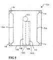
- Figure 5 shows a heat protective article 100 that includes additional features that may be incorporated in any of the articles 10, 50 and 80 previously described.
- the heat protective article 100 is a substantially rectangular mat made of a heat resistant material and has a through-hole 102 and a slit 104 extending from an edge 106 of the mat to the through-hole.
- a flap 108 preferably made of the same material as the mat, is provided for covering the slit.
- the flap 108 is preferably attached to the mat by heat-resistant stitching provided along the left-hand side of the flap (as viewed in Figure 3), although other attaching means, such as metal press-studs, could be used.
- One half of a hook and loop fastener material 110 of the Velco-type is provided along the right-hand side of the flap 108.
- the other half of the fastener material (not shown) is attached to the mat so that it faces the half 110.
- a strip of the fastener material extends the whole length of the flap 108.
- two separate pieces may be provided, with one positioned adjacent the through-hole 102 and the other positioned adjacent the edge 106.
- Respective pockets 112, 114, 116, 118 are formed at the corners of the mat by attaching triangular pieces of material at the corners.
- the triangular pieces of material are preferably made of the same material as the mat and attached by heat-resistant stitching.
- opposed pockets 120, 122 are provided on the flap 108 adjacent the edge 106
- Stiffening rods 124, 126 are provided for fitting in the pockets 112 to 122.
- the stiffening rods 124, 126 respectively extend between the pockets 112, 118 and 114, 116. In Figure 5, only two such rods are shown. However, the skilled person will appreciate that in an analogous fashion, respective stiffening rods may extend between the pockets 112, 114, the pockets 118, 120 and the pockets 116, 122.
- the stiffening rods are preferably made of are resilient circular section steel rodding.
- the stiffening rods are configured such that they can readily be bent to shorten their length to allow them to fit into the pockets and once in their pockets will resile to their normal length to provide a brace, or stiffener, for the mat.
- stiffening members of any suitable shape and material may be used.
- the stiffening rods can, for example, advantageously be used where the heat protective article is to be used to shield the area around a horizontal pipe to which heat is to be applied. It will be appreciated that some of the rods may be fitted in their pockets prior to fitting the heat protective article around the pipe, or all may be fitted once the mat is in place. Once fitted, the stiffening rods prevent the mat from folding over, thereby providing a semi-stiff screen.
- two pockets 120, 122 are provided on the flap 108.
- pockets may be provided behind the pockets 116, 118 on the opposite side of the mat.
- pockets can be provided at intermediate positions along the edges of the mat. These could be used in conjunction with stiffening rods or members formed with, for example, a 90° bend, so that the mat can be stiffened in such a way as to maintain a partially-folded state.
- the heat protective article is intended primarily for use by plumbers soldering pipework, it is not limited to such use and may be used generally for protecting surfaces around an elongate element to which heat is to be applied.
Landscapes
- Engineering & Computer Science (AREA)
- General Engineering & Computer Science (AREA)
- Mechanical Engineering (AREA)
- Emergency Management (AREA)
- Health & Medical Sciences (AREA)
- Business, Economics & Management (AREA)
- Public Health (AREA)
- Thermal Insulation (AREA)
- Laminated Bodies (AREA)
- Packages (AREA)
- Thermotherapy And Cooling Therapy Devices (AREA)
- Gloves (AREA)
- Flanged Joints, Insulating Joints, And Other Joints (AREA)
- Professional, Industrial, Or Sporting Protective Garments (AREA)
- Lining Or Joining Of Plastics Or The Like (AREA)
Applications Claiming Priority (2)
| Application Number | Priority Date | Filing Date | Title |
|---|---|---|---|
| GB0408220 | 2004-04-13 | ||
| GB0408220A GB2406515B (en) | 2004-04-13 | 2004-04-13 | Heat protective articles |
Publications (3)
| Publication Number | Publication Date |
|---|---|
| EP1586409A1 true EP1586409A1 (de) | 2005-10-19 |
| EP1586409B1 EP1586409B1 (de) | 2008-12-03 |
| EP1586409B8 EP1586409B8 (de) | 2009-02-25 |
Family
ID=32320746
Family Applications (1)
| Application Number | Title | Priority Date | Filing Date |
|---|---|---|---|
| EP05252185A Expired - Lifetime EP1586409B8 (de) | 2004-04-13 | 2005-04-07 | Thermische Schutzvorrichtung |
Country Status (6)
| Country | Link |
|---|---|
| US (1) | US20050227041A1 (de) |
| EP (1) | EP1586409B8 (de) |
| AT (1) | ATE416059T1 (de) |
| DE (1) | DE602005011352D1 (de) |
| ES (1) | ES2318430T3 (de) |
| GB (1) | GB2406515B (de) |
Families Citing this family (3)
| Publication number | Priority date | Publication date | Assignee | Title |
|---|---|---|---|---|
| US20070207288A1 (en) * | 2006-03-03 | 2007-09-06 | Patricia Almeter | Towel |
| RU188762U1 (ru) * | 2019-01-10 | 2019-04-23 | Общество с ограниченной ответственностью "Пожнефтехим" | Устройство для защиты от теплового потока |
| GB2571457B (en) * | 2019-03-29 | 2020-04-01 | Gamasco Ltd | A Heat Resistant Pad |
Citations (4)
| Publication number | Priority date | Publication date | Assignee | Title |
|---|---|---|---|---|
| GB751910A (en) * | 1953-07-08 | 1956-07-04 | Sievert Ab Max | Improvements in heat protection or heat screen devices |
| GB2103331A (en) * | 1981-06-27 | 1983-02-16 | Promat | Heat-insulating casing for elongate constructional parts |
| US5241154A (en) * | 1991-12-06 | 1993-08-31 | Mig-It Inc. | Shield for mig welder |
| US6161590A (en) * | 1999-11-15 | 2000-12-19 | 844426 Alberta Ltd. | Welder's windguard |
Family Cites Families (8)
| Publication number | Priority date | Publication date | Assignee | Title |
|---|---|---|---|---|
| US2410306A (en) * | 1944-10-18 | 1946-10-29 | Raymond A Romberg | Welding shield or the like |
| US3059378A (en) * | 1960-05-05 | 1962-10-23 | Frank H Noras | Tree pads |
| US3650869A (en) * | 1969-07-07 | 1972-03-21 | Minnesota Mining & Mfg | Protective pad and method of using |
| US4795669A (en) * | 1987-01-28 | 1989-01-03 | Bowskill Mary J | Disposable protective shield for handle of illumination device |
| US5509231A (en) * | 1994-02-14 | 1996-04-23 | Flexstake, Inc. | Method of retarding vegetation growth |
| GB9803931D0 (en) * | 1998-02-26 | 1998-04-22 | Kovacs Laurence K | Intumescent collar |
| US6128852A (en) * | 1999-04-19 | 2000-10-10 | Hansen; Merrill J. | Landscaping tarp for covering stones or wood chips about tree or bush |
| US20040192133A1 (en) * | 2000-07-06 | 2004-09-30 | Higher Dimension Medical, Inc. | Abrasion and heat resistant fabrics |
-
2004
- 2004-04-13 GB GB0408220A patent/GB2406515B/en not_active Expired - Lifetime
-
2005
- 2005-04-07 AT AT05252185T patent/ATE416059T1/de not_active IP Right Cessation
- 2005-04-07 ES ES05252185T patent/ES2318430T3/es not_active Expired - Lifetime
- 2005-04-07 DE DE602005011352T patent/DE602005011352D1/de not_active Expired - Lifetime
- 2005-04-07 EP EP05252185A patent/EP1586409B8/de not_active Expired - Lifetime
- 2005-04-13 US US11/105,014 patent/US20050227041A1/en not_active Abandoned
Patent Citations (4)
| Publication number | Priority date | Publication date | Assignee | Title |
|---|---|---|---|---|
| GB751910A (en) * | 1953-07-08 | 1956-07-04 | Sievert Ab Max | Improvements in heat protection or heat screen devices |
| GB2103331A (en) * | 1981-06-27 | 1983-02-16 | Promat | Heat-insulating casing for elongate constructional parts |
| US5241154A (en) * | 1991-12-06 | 1993-08-31 | Mig-It Inc. | Shield for mig welder |
| US6161590A (en) * | 1999-11-15 | 2000-12-19 | 844426 Alberta Ltd. | Welder's windguard |
Also Published As
| Publication number | Publication date |
|---|---|
| GB0408220D0 (en) | 2004-05-19 |
| ATE416059T1 (de) | 2008-12-15 |
| GB2406515B (en) | 2005-12-14 |
| DE602005011352D1 (de) | 2009-01-15 |
| GB2406515A (en) | 2005-04-06 |
| EP1586409B8 (de) | 2009-02-25 |
| ES2318430T3 (es) | 2009-05-01 |
| US20050227041A1 (en) | 2005-10-13 |
| EP1586409B1 (de) | 2008-12-03 |
Similar Documents
| Publication | Publication Date | Title |
|---|---|---|
| EP1239118B1 (de) | Flexible Textildichtung für Turbinenbrennkammern | |
| EP1586409B1 (de) | Thermische Schutzvorrichtung | |
| US5005879A (en) | Corner bracket and interconnection system for ducting | |
| CA2538740C (en) | Heat protective articles | |
| AU2006200948B2 (en) | Heat protective articles | |
| US3988030A (en) | Slip-joint coupling, method of installing same and frame subassembly for use therewith | |
| KR101780594B1 (ko) | 빗물 침투를 방지한 배관 단열재용 덕트 | |
| JP6059834B1 (ja) | 管路固定構造 | |
| PL64785Y1 (pl) | Płyta izolacyjna z połączeniem do szybkiego mocowania przewodów do rozprowadzania powietrza, zwłaszcza powietrza klimatyzowanego | |
| US20040016470A1 (en) | Duct wrap securing system | |
| US5607355A (en) | Mounting bracket for damper | |
| US11439273B2 (en) | Adjustable grill cover assembly | |
| KR200453358Y1 (ko) | 선박용 슬라이드 족장 | |
| US11051614B1 (en) | Wash/sanitation rack for athletic equipment | |
| US20200305663A1 (en) | Splash Shield Assembly | |
| JP2010236689A (ja) | 流体管用遮音カバー | |
| US12276108B1 (en) | Step flashing and moisture barrier assembly and method therefor | |
| JPH09318087A (ja) | 温水床パネル | |
| WO2015104526A1 (en) | Apparatus and method for attaching a habitat to a structural element | |
| JP2020005543A (ja) | 妻面保護カバー | |
| ES1314891U (es) | Cobertor de proteccion | |
| EP3634740A1 (de) | Matte zum schutz vor hochtemperaturartikeln | |
| JP2010505633A (ja) | グローブボックスの開口に使用される可撓性グローブホルダ | |
| KR20230002104U (ko) | 모듈형 배관 고정 장치 | |
| CN206973842U (zh) | 一种屏蔽进排风口 |
Legal Events
| Date | Code | Title | Description |
|---|---|---|---|
| PUAI | Public reference made under article 153(3) epc to a published international application that has entered the european phase |
Free format text: ORIGINAL CODE: 0009012 |
|
| AK | Designated contracting states |
Kind code of ref document: A1 Designated state(s): AT BE BG CH CY CZ DE DK EE ES FI FR GB GR HU IE IS IT LI LT LU MC NL PL PT RO SE SI SK TR |
|
| AX | Request for extension of the european patent |
Extension state: AL BA HR LV MK YU |
|
| 17P | Request for examination filed |
Effective date: 20060419 |
|
| AKX | Designation fees paid |
Designated state(s): AT BE BG CH CY CZ DE DK EE ES FI FR GB GR HU IE IS IT LI LT LU MC NL PL PT RO SE SI SK TR |
|
| GRAP | Despatch of communication of intention to grant a patent |
Free format text: ORIGINAL CODE: EPIDOSNIGR1 |
|
| GRAS | Grant fee paid |
Free format text: ORIGINAL CODE: EPIDOSNIGR3 |
|
| GRAS | Grant fee paid |
Free format text: ORIGINAL CODE: EPIDOSNIGR3 |
|
| GRAA | (expected) grant |
Free format text: ORIGINAL CODE: 0009210 |
|
| AK | Designated contracting states |
Kind code of ref document: B1 Designated state(s): AT BE BG CH CY CZ DE DK EE ES FI FR GB GR HU IE IS IT LI LT LU MC NL PL PT RO SE SI SK TR |
|
| REG | Reference to a national code |
Ref country code: GB Ref legal event code: FG4D |
|
| REG | Reference to a national code |
Ref country code: CH Ref legal event code: EP |
|
| RAP2 | Party data changed (patent owner data changed or rights of a patent transferred) |
Owner name: THOMAS, DEAN WILLIAM |
|
| RIN2 | Information on inventor provided after grant (corrected) |
Inventor name: THOMAS, DEAN WILLIAM |
|
| RBV | Designated contracting states (corrected) |
Designated state(s): AT BE BG CH CY CZ DE DK EE ES FI FR GR HU IE IS IT LI LT LU MC NL PL PT RO SE SI SK TR |
|
| REG | Reference to a national code |
Ref country code: IE Ref legal event code: FG4D |
|
| REF | Corresponds to: |
Ref document number: 602005011352 Country of ref document: DE Date of ref document: 20090115 Kind code of ref document: P |
|
| PG25 | Lapsed in a contracting state [announced via postgrant information from national office to epo] |
Ref country code: LT Free format text: LAPSE BECAUSE OF FAILURE TO SUBMIT A TRANSLATION OF THE DESCRIPTION OR TO PAY THE FEE WITHIN THE PRESCRIBED TIME-LIMIT Effective date: 20081203 |
|
| REG | Reference to a national code |
Ref country code: ES Ref legal event code: FG2A Ref document number: 2318430 Country of ref document: ES Kind code of ref document: T3 |
|
| NLV1 | Nl: lapsed or annulled due to failure to fulfill the requirements of art. 29p and 29m of the patents act | ||
| PG25 | Lapsed in a contracting state [announced via postgrant information from national office to epo] |
Ref country code: PL Free format text: LAPSE BECAUSE OF FAILURE TO SUBMIT A TRANSLATION OF THE DESCRIPTION OR TO PAY THE FEE WITHIN THE PRESCRIBED TIME-LIMIT Effective date: 20081203 Ref country code: NL Free format text: LAPSE BECAUSE OF FAILURE TO SUBMIT A TRANSLATION OF THE DESCRIPTION OR TO PAY THE FEE WITHIN THE PRESCRIBED TIME-LIMIT Effective date: 20081203 Ref country code: FI Free format text: LAPSE BECAUSE OF FAILURE TO SUBMIT A TRANSLATION OF THE DESCRIPTION OR TO PAY THE FEE WITHIN THE PRESCRIBED TIME-LIMIT Effective date: 20081203 Ref country code: SI Free format text: LAPSE BECAUSE OF FAILURE TO SUBMIT A TRANSLATION OF THE DESCRIPTION OR TO PAY THE FEE WITHIN THE PRESCRIBED TIME-LIMIT Effective date: 20081203 |
|
| PG25 | Lapsed in a contracting state [announced via postgrant information from national office to epo] |
Ref country code: BG Free format text: LAPSE BECAUSE OF FAILURE TO SUBMIT A TRANSLATION OF THE DESCRIPTION OR TO PAY THE FEE WITHIN THE PRESCRIBED TIME-LIMIT Effective date: 20090303 Ref country code: BE Free format text: LAPSE BECAUSE OF FAILURE TO SUBMIT A TRANSLATION OF THE DESCRIPTION OR TO PAY THE FEE WITHIN THE PRESCRIBED TIME-LIMIT Effective date: 20081203 Ref country code: EE Free format text: LAPSE BECAUSE OF FAILURE TO SUBMIT A TRANSLATION OF THE DESCRIPTION OR TO PAY THE FEE WITHIN THE PRESCRIBED TIME-LIMIT Effective date: 20081203 Ref country code: RO Free format text: LAPSE BECAUSE OF FAILURE TO SUBMIT A TRANSLATION OF THE DESCRIPTION OR TO PAY THE FEE WITHIN THE PRESCRIBED TIME-LIMIT Effective date: 20081203 |
|
| PG25 | Lapsed in a contracting state [announced via postgrant information from national office to epo] |
Ref country code: PT Free format text: LAPSE BECAUSE OF FAILURE TO SUBMIT A TRANSLATION OF THE DESCRIPTION OR TO PAY THE FEE WITHIN THE PRESCRIBED TIME-LIMIT Effective date: 20090504 Ref country code: SE Free format text: LAPSE BECAUSE OF FAILURE TO SUBMIT A TRANSLATION OF THE DESCRIPTION OR TO PAY THE FEE WITHIN THE PRESCRIBED TIME-LIMIT Effective date: 20090303 Ref country code: IS Free format text: LAPSE BECAUSE OF FAILURE TO SUBMIT A TRANSLATION OF THE DESCRIPTION OR TO PAY THE FEE WITHIN THE PRESCRIBED TIME-LIMIT Effective date: 20090403 Ref country code: CZ Free format text: LAPSE BECAUSE OF FAILURE TO SUBMIT A TRANSLATION OF THE DESCRIPTION OR TO PAY THE FEE WITHIN THE PRESCRIBED TIME-LIMIT Effective date: 20081203 Ref country code: AT Free format text: LAPSE BECAUSE OF FAILURE TO SUBMIT A TRANSLATION OF THE DESCRIPTION OR TO PAY THE FEE WITHIN THE PRESCRIBED TIME-LIMIT Effective date: 20081203 |
|
| PG25 | Lapsed in a contracting state [announced via postgrant information from national office to epo] |
Ref country code: SK Free format text: LAPSE BECAUSE OF FAILURE TO SUBMIT A TRANSLATION OF THE DESCRIPTION OR TO PAY THE FEE WITHIN THE PRESCRIBED TIME-LIMIT Effective date: 20081203 |
|
| PLBE | No opposition filed within time limit |
Free format text: ORIGINAL CODE: 0009261 |
|
| STAA | Information on the status of an ep patent application or granted ep patent |
Free format text: STATUS: NO OPPOSITION FILED WITHIN TIME LIMIT |
|
| PG25 | Lapsed in a contracting state [announced via postgrant information from national office to epo] |
Ref country code: DK Free format text: LAPSE BECAUSE OF FAILURE TO SUBMIT A TRANSLATION OF THE DESCRIPTION OR TO PAY THE FEE WITHIN THE PRESCRIBED TIME-LIMIT Effective date: 20081203 |
|
| 26N | No opposition filed |
Effective date: 20090904 |
|
| REG | Reference to a national code |
Ref country code: CH Ref legal event code: PL |
|
| PG25 | Lapsed in a contracting state [announced via postgrant information from national office to epo] |
Ref country code: LI Free format text: LAPSE BECAUSE OF NON-PAYMENT OF DUE FEES Effective date: 20090430 Ref country code: CH Free format text: LAPSE BECAUSE OF NON-PAYMENT OF DUE FEES Effective date: 20090430 |
|
| PG25 | Lapsed in a contracting state [announced via postgrant information from national office to epo] |
Ref country code: MC Free format text: LAPSE BECAUSE OF NON-PAYMENT OF DUE FEES Effective date: 20090430 |
|
| PG25 | Lapsed in a contracting state [announced via postgrant information from national office to epo] |
Ref country code: GR Free format text: LAPSE BECAUSE OF FAILURE TO SUBMIT A TRANSLATION OF THE DESCRIPTION OR TO PAY THE FEE WITHIN THE PRESCRIBED TIME-LIMIT Effective date: 20090304 |
|
| PG25 | Lapsed in a contracting state [announced via postgrant information from national office to epo] |
Ref country code: LU Free format text: LAPSE BECAUSE OF NON-PAYMENT OF DUE FEES Effective date: 20090407 |
|
| PG25 | Lapsed in a contracting state [announced via postgrant information from national office to epo] |
Ref country code: HU Free format text: LAPSE BECAUSE OF FAILURE TO SUBMIT A TRANSLATION OF THE DESCRIPTION OR TO PAY THE FEE WITHIN THE PRESCRIBED TIME-LIMIT Effective date: 20090604 |
|
| PG25 | Lapsed in a contracting state [announced via postgrant information from national office to epo] |
Ref country code: TR Free format text: LAPSE BECAUSE OF FAILURE TO SUBMIT A TRANSLATION OF THE DESCRIPTION OR TO PAY THE FEE WITHIN THE PRESCRIBED TIME-LIMIT Effective date: 20081203 |
|
| PG25 | Lapsed in a contracting state [announced via postgrant information from national office to epo] |
Ref country code: CY Free format text: LAPSE BECAUSE OF FAILURE TO SUBMIT A TRANSLATION OF THE DESCRIPTION OR TO PAY THE FEE WITHIN THE PRESCRIBED TIME-LIMIT Effective date: 20081203 |
|
| REG | Reference to a national code |
Ref country code: FR Ref legal event code: PLFP Year of fee payment: 11 |
|
| REG | Reference to a national code |
Ref country code: FR Ref legal event code: PLFP Year of fee payment: 12 |
|
| REG | Reference to a national code |
Ref country code: FR Ref legal event code: PLFP Year of fee payment: 13 |
|
| REG | Reference to a national code |
Ref country code: DE Ref legal event code: R082 Ref document number: 602005011352 Country of ref document: DE |
|
| REG | Reference to a national code |
Ref country code: FR Ref legal event code: PLFP Year of fee payment: 14 |
|
| PGFP | Annual fee paid to national office [announced via postgrant information from national office to epo] |
Ref country code: IT Payment date: 20231030 Year of fee payment: 19 Ref country code: IE Payment date: 20231031 Year of fee payment: 19 Ref country code: FR Payment date: 20231031 Year of fee payment: 19 Ref country code: DE Payment date: 20231030 Year of fee payment: 19 |
|
| PGFP | Annual fee paid to national office [announced via postgrant information from national office to epo] |
Ref country code: ES Payment date: 20240430 Year of fee payment: 19 |
|
| REG | Reference to a national code |
Ref country code: DE Ref legal event code: R119 Ref document number: 602005011352 Country of ref document: DE |
|
| PG25 | Lapsed in a contracting state [announced via postgrant information from national office to epo] |
Ref country code: DE Free format text: LAPSE BECAUSE OF NON-PAYMENT OF DUE FEES Effective date: 20241105 |
|
| PG25 | Lapsed in a contracting state [announced via postgrant information from national office to epo] |
Ref country code: FR Free format text: LAPSE BECAUSE OF NON-PAYMENT OF DUE FEES Effective date: 20240430 |
|
| PG25 | Lapsed in a contracting state [announced via postgrant information from national office to epo] |
Ref country code: FR Free format text: LAPSE BECAUSE OF NON-PAYMENT OF DUE FEES Effective date: 20240430 Ref country code: DE Free format text: LAPSE BECAUSE OF NON-PAYMENT OF DUE FEES Effective date: 20241105 |
|
| PG25 | Lapsed in a contracting state [announced via postgrant information from national office to epo] |
Ref country code: IE Free format text: LAPSE BECAUSE OF NON-PAYMENT OF DUE FEES Effective date: 20240407 |
|
| PG25 | Lapsed in a contracting state [announced via postgrant information from national office to epo] |
Ref country code: IT Free format text: LAPSE BECAUSE OF NON-PAYMENT OF DUE FEES Effective date: 20240407 |
|
| REG | Reference to a national code |
Ref country code: ES Ref legal event code: FD2A Effective date: 20250528 |
|
| PG25 | Lapsed in a contracting state [announced via postgrant information from national office to epo] |
Ref country code: ES Free format text: LAPSE BECAUSE OF NON-PAYMENT OF DUE FEES Effective date: 20240408 |