EP1586389A1 - Vorrichtung zur herstellung eines metallrohrs mit ovalem querschnitt und herstellungsverfahren - Google Patents
Vorrichtung zur herstellung eines metallrohrs mit ovalem querschnitt und herstellungsverfahren Download PDFInfo
- Publication number
- EP1586389A1 EP1586389A1 EP03771321A EP03771321A EP1586389A1 EP 1586389 A1 EP1586389 A1 EP 1586389A1 EP 03771321 A EP03771321 A EP 03771321A EP 03771321 A EP03771321 A EP 03771321A EP 1586389 A1 EP1586389 A1 EP 1586389A1
- Authority
- EP
- European Patent Office
- Prior art keywords
- punch
- metal tube
- oval cross
- section
- taper
- Prior art date
- Legal status (The legal status is an assumption and is not a legal conclusion. Google has not performed a legal analysis and makes no representation as to the accuracy of the status listed.)
- Granted
Links
Images









Classifications
-
- B—PERFORMING OPERATIONS; TRANSPORTING
- B21—MECHANICAL METAL-WORKING WITHOUT ESSENTIALLY REMOVING MATERIAL; PUNCHING METAL
- B21C—MANUFACTURE OF METAL SHEETS, WIRE, RODS, TUBES, PROFILES OR LIKE SEMI-MANUFACTURED PRODUCTS OTHERWISE THAN BY ROLLING; AUXILIARY OPERATIONS USED IN CONNECTION WITH METAL-WORKING WITHOUT ESSENTIALLY REMOVING MATERIAL
- B21C23/00—Extruding metal; Impact extrusion
- B21C23/21—Presses specially adapted for extruding metal
- B21C23/217—Tube extrusion presses
-
- B—PERFORMING OPERATIONS; TRANSPORTING
- B21—MECHANICAL METAL-WORKING WITHOUT ESSENTIALLY REMOVING MATERIAL; PUNCHING METAL
- B21C—MANUFACTURE OF METAL SHEETS, WIRE, RODS, TUBES, PROFILES OR LIKE SEMI-MANUFACTURED PRODUCTS OTHERWISE THAN BY ROLLING; AUXILIARY OPERATIONS USED IN CONNECTION WITH METAL-WORKING WITHOUT ESSENTIALLY REMOVING MATERIAL
- B21C23/00—Extruding metal; Impact extrusion
- B21C23/02—Making uncoated products
- B21C23/18—Making uncoated products by impact extrusion
- B21C23/186—Making uncoated products by impact extrusion by backward extrusion
-
- B—PERFORMING OPERATIONS; TRANSPORTING
- B21—MECHANICAL METAL-WORKING WITHOUT ESSENTIALLY REMOVING MATERIAL; PUNCHING METAL
- B21C—MANUFACTURE OF METAL SHEETS, WIRE, RODS, TUBES, PROFILES OR LIKE SEMI-MANUFACTURED PRODUCTS OTHERWISE THAN BY ROLLING; AUXILIARY OPERATIONS USED IN CONNECTION WITH METAL-WORKING WITHOUT ESSENTIALLY REMOVING MATERIAL
- B21C25/00—Profiling tools for metal extruding
- B21C25/02—Dies
Definitions
- the impact extrusion device includes a columnar punch having an axis, a press die, and a stripper provided around the punch in an axially movable manner.
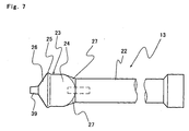
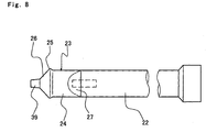
- the punch includes a punch shaft, a punch head provided at a distal end of the shaft and including a punch shoulder.
- the die includes a die base, and a die ring which retains the metal slug therein.
- the die base and the die ring may be a unitary member or separate members combined together.
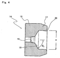
- the punch shoulder has an outer surface having an oval cross section, and the die ring has an inner peripheral surface having an oval cross section.
- the punch shoulder is insertable in the die ring.
- a gap is defined between the die ring and the punch shoulder inserted in the die ring circumferentially of the punch shoulder. The metal material is extruded through the gap, whereby the metal tube is allowed to have an oval body.
- the punch head includes a base of an oval cross section connected to the punch shaft, the punch shoulder which is provided at a distal end of the base and has a greater diameter than the base, and a first taper surface having an oval cross section which has a diameter progressively decreasing toward a distal end thereof from the punch shoulder.
- Generating lines of the first taper surface on diametrically opposite sides of the major axis of the first taper surface preferably each form an angle of not smaller than 55 degrees and not greater than 65 degrees with respect to the axis of the punch.
- generating lines of the first taper surface on diametrically opposite sides of the minor axis of the first taper surface preferably each form an angle of not smaller than 43 degrees and not greater than 53 degrees with respect to the axis of the punch.
- the outer surface of the shoulder and the inner peripheral surface of the die ring are each preferably dimensioned so that the ratio of the minor axis to the major axis thereof is not smaller than 0.6 and not greater than 0.9.
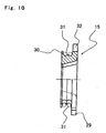
- the hem portion of the metal tube fitted around the mandrel is flared into a circular shape by the taper portion.
- the metal tube having the flared hem portion is rotated relative to the cutting tool by the rotation of the mandrel, whereby the hem portion of the tube is circumferentially cut by the cutting tool.
- the body and the shoulder each have an oval shape, so that the shoulder can be easily collapsed along the minor axis thereof.
- a metal tube including a mouth, a shoulder and a body integrally formed has a disadvantage such that contents are likely to partly remain in the shoulder of the metal tube, the present invention eliminates this disadvantage. Since the metal tube has an oval shape, a multiplicity of such tubes can be efficiently stored by arranging the tubes in a proper direction.
- the first taper surface 26 of the punch head 23 defines an interior surface of the shoulder of the tube, and conforms to the shape of the taper surface 18 of the die base 16. Generating lines of the first taper surface 26 on diametrically opposite sides of the major axis of the first taper surface each preferably form an angle of about 60 degrees with respect to the axis of the punch, and generating lines on diametrically opposite sides of the minor axis of the first taper surface 26 each preferably form an angle of about 49 degrees with respect to the axis of the punch.
- the inclination angles of the first taper surface 26 may be equal to the inclination angles of the shoulder defining taper surface 18 of the die base 16 throughout the circumference of the punch head.
Landscapes
- Engineering & Computer Science (AREA)
- Mechanical Engineering (AREA)
- Extrusion Of Metal (AREA)
- Forging (AREA)
- Tubes (AREA)
- Press Drives And Press Lines (AREA)
Applications Claiming Priority (3)
| Application Number | Priority Date | Filing Date | Title |
|---|---|---|---|
| JP2002218381 | 2002-07-26 | ||
| JP2002218381A JP4145594B2 (ja) | 2002-07-26 | 2002-07-26 | 断面楕円形金属チューブ、及び、その製造装置並びに製造方法 |
| PCT/JP2003/009419 WO2004011167A1 (ja) | 2002-07-26 | 2003-07-25 | 断面楕円形金属チューブの製造装置並びに製造方法 |
Publications (3)
| Publication Number | Publication Date |
|---|---|
| EP1586389A1 true EP1586389A1 (de) | 2005-10-19 |
| EP1586389A4 EP1586389A4 (de) | 2007-10-17 |
| EP1586389B1 EP1586389B1 (de) | 2008-10-08 |
Family
ID=31184677
Family Applications (1)
| Application Number | Title | Priority Date | Filing Date |
|---|---|---|---|
| EP03771321A Expired - Lifetime EP1586389B1 (de) | 2002-07-26 | 2003-07-25 | Vorrichtung zur herstellung eines metallrohrs mit ovalem querschnitt und herstellungsverfahren |
Country Status (6)
| Country | Link |
|---|---|
| US (1) | US7219522B2 (de) |
| EP (1) | EP1586389B1 (de) |
| JP (1) | JP4145594B2 (de) |
| AU (1) | AU2003255157A1 (de) |
| DE (1) | DE60324030D1 (de) |
| WO (1) | WO2004011167A1 (de) |
Cited By (2)
| Publication number | Priority date | Publication date | Assignee | Title |
|---|---|---|---|---|
| CN103042061A (zh) * | 2013-01-08 | 2013-04-17 | 青岛勤德索具有限公司 | 智能化管内径变径系统及管内径变径方法 |
| EP4545196A1 (de) * | 2023-10-25 | 2025-04-30 | LINHARDT Viechtach GmbH & Co. KG | Vorrichtung zur herstellung kleinvolumiger tubenverpackungsrohlinge |
Families Citing this family (15)
| Publication number | Priority date | Publication date | Assignee | Title |
|---|---|---|---|---|
| WO2007028865A1 (fr) * | 2005-09-02 | 2007-03-15 | Thermagen, Sa | Dispositif de refrigeration |
| KR100845421B1 (ko) | 2007-01-17 | 2008-07-10 | 주식회사화신 | 자동차의 크로스멤버용 컵의 제조방법 |
| KR101188576B1 (ko) * | 2007-06-29 | 2012-10-05 | 게케엔 드리펠린 인터나쇼날 게엠베하 | 가늘고 긴 중공체의 축 형성을 위한 장치 및 방법 |
| JP2009067401A (ja) * | 2007-09-11 | 2009-04-02 | Kansai Tube Kk | 金属チューブ容器及びその製造方法 |
| US8073524B2 (en) * | 2007-11-08 | 2011-12-06 | Imris Inc. | Control of magnetic field homogeneity in movable MRI scanning system |
| JP2012240723A (ja) * | 2011-05-20 | 2012-12-10 | Takeuchi Press Ind Co Ltd | チューブ容器 |
| DE102011080769A1 (de) * | 2011-08-10 | 2013-02-14 | Mall + Herlan Gmbh | Effektive Produktionslinie für Aerosoldosen |
| JP5929619B2 (ja) | 2012-08-10 | 2016-06-08 | 富士ゼロックス株式会社 | 筒状部材 |
| CA2944672A1 (en) * | 2014-04-11 | 2015-10-15 | iMOLZ, LLC | Non-round metallic pressurized container and method of manufacturing same |
| KR101432776B1 (ko) * | 2014-05-09 | 2014-09-22 | 린노알미늄 주식회사 | 임팩트 프레스기의 성형품 분리장치 |
| DE102016121089A1 (de) | 2016-11-04 | 2018-05-09 | Schuler Pressen Gmbh | Verfahren und Vorrichtung zur Herstellung eines prismatischen Batteriezellenbehälters |
| CN112620372B (zh) * | 2020-12-23 | 2022-05-24 | 太原理工大学 | 连续差速挤压制备弱基面织构镁合金板带材的模具及方法 |
| CN113102599B (zh) * | 2021-04-26 | 2024-12-10 | 勋龙智造精密应用材料(苏州)股份有限公司 | 一种用于模具封水机构的冲击头 |
| CN114770138B (zh) * | 2022-05-10 | 2025-06-17 | 沈阳泰德自动化设备有限公司 | 一种方型薄壁储能电池壳卧式挤压成型生产线 |
| KR20250023663A (ko) * | 2023-08-10 | 2025-02-18 | 삼성에스디아이 주식회사 | 각형 캔 제조 장치 |
Family Cites Families (10)
| Publication number | Priority date | Publication date | Assignee | Title |
|---|---|---|---|---|
| US2162776A (en) * | 1936-11-20 | 1939-06-20 | Sun Tube Corp | Apparatus for and method of making thin metal containers |
| US2161752A (en) * | 1938-02-16 | 1939-06-06 | Victor Metal Products Corp | Stripper for collapsible tube extruding presses |
| US2533942A (en) * | 1948-05-06 | 1950-12-12 | Western Electric Co | Extruding apparatus |
| US2789344A (en) * | 1951-04-23 | 1957-04-23 | American Radiator & Standard | Method of cold shaping tubular steel articles and product |
| US2979195A (en) * | 1956-09-26 | 1961-04-11 | Procter & Gamble | Method of and apparatus for extruding metal collapsible tubes |
| US3415098A (en) * | 1966-03-08 | 1968-12-10 | Gen Electric | Method of extruding capacitor cases |
| BE791879A (fr) * | 1971-11-25 | 1973-05-24 | Scal Gp Condit Aluminium | Procede de fabrication de tubes souples coniques |
| JPS53133570A (en) * | 1977-04-28 | 1978-11-21 | Kyodo Printing Co Ltd | Manufacturing method of compound tube |
| JPH0265447A (ja) | 1988-08-31 | 1990-03-06 | Matsushita Electric Ind Co Ltd | 無線装置 |
| JPH0543958Y2 (de) * | 1988-11-01 | 1993-11-08 |
-
2002
- 2002-07-26 JP JP2002218381A patent/JP4145594B2/ja not_active Expired - Fee Related
-
2003
- 2003-07-25 WO PCT/JP2003/009419 patent/WO2004011167A1/ja not_active Ceased
- 2003-07-25 DE DE60324030T patent/DE60324030D1/de not_active Expired - Lifetime
- 2003-07-25 EP EP03771321A patent/EP1586389B1/de not_active Expired - Lifetime
- 2003-07-25 AU AU2003255157A patent/AU2003255157A1/en not_active Abandoned
- 2003-07-25 US US10/522,217 patent/US7219522B2/en not_active Expired - Fee Related
Cited By (2)
| Publication number | Priority date | Publication date | Assignee | Title |
|---|---|---|---|---|
| CN103042061A (zh) * | 2013-01-08 | 2013-04-17 | 青岛勤德索具有限公司 | 智能化管内径变径系统及管内径变径方法 |
| EP4545196A1 (de) * | 2023-10-25 | 2025-04-30 | LINHARDT Viechtach GmbH & Co. KG | Vorrichtung zur herstellung kleinvolumiger tubenverpackungsrohlinge |
Also Published As
| Publication number | Publication date |
|---|---|
| JP2004058087A (ja) | 2004-02-26 |
| AU2003255157A1 (en) | 2004-02-16 |
| WO2004011167A1 (ja) | 2004-02-05 |
| EP1586389A4 (de) | 2007-10-17 |
| US7219522B2 (en) | 2007-05-22 |
| EP1586389B1 (de) | 2008-10-08 |
| US20050247097A1 (en) | 2005-11-10 |
| JP4145594B2 (ja) | 2008-09-03 |
| DE60324030D1 (de) | 2008-11-20 |
Similar Documents
| Publication | Publication Date | Title |
|---|---|---|
| US7219522B2 (en) | Oval cross section metal tube producing device and producing method | |
| US7555927B2 (en) | Bottle-shaped can manufacturing method and bottle-shaped can | |
| EP2871022B1 (de) | Rollierwerkzeug | |
| CN100391672C (zh) | 系紧螺钉的旋钮和套环的制造方法 | |
| WO1996016754A1 (en) | Method of necking an impact extruded metal container | |
| JP4149191B2 (ja) | 金属製ボトル缶の製造方法および製造装置 | |
| KR20060092202A (ko) | 보틀 캔 제조장치 | |
| US20100227695A1 (en) | Inner Ring for Constant Velocity Universal Joint and Manufacturing Apparatus Therefor | |
| US4554810A (en) | Draw-spinning of integral vehicle wheel rim and disc segments | |
| US20040011112A1 (en) | Device and method for the widening and forming of a can body | |
| US3727254A (en) | Method of forming an insert bush | |
| US4967583A (en) | Method of manufacturing extruded seamless hollow materials | |
| TWI787960B (zh) | 罐體之製造方法及罐體的生產線 | |
| JPH0760336A (ja) | 中空ステアリングシャフトの製造方法 | |
| JP6887363B2 (ja) | 缶の製造方法 | |
| JP2007229807A (ja) | 金属製ボトル缶の製造方法および製造装置 | |
| US11951527B2 (en) | Method for producing a ball raceway on a workpiece and a ball screw nut having a ball raceway thus produced | |
| US7062948B2 (en) | Process of end-forming a tube having internal surface features | |
| US4758149A (en) | Capsule forming pin having a burnish-hardened surface | |
| DE102023121770B3 (de) | Verfahren zur Herstellung einer Rotorhohlwelle | |
| CA2546338A1 (en) | Method for the production of a flange on a metal blank, and transmission part | |
| JP2011045915A (ja) | 転動成形型とそれを用いた筒状金具の製造方法,筒状金具を用いた防振ゴムブッシュの製造方法 | |
| US3733880A (en) | Apparatus for and method of facilitating the stripping of cans from a punch and the article formed thereby | |
| EP4547570A1 (de) | Verschluss mit gewinde aus metall zum verschliessen eines behälters und verfahren zur herstellung | |
| CN111097979A (zh) | 具有凸起脊的螺纹成型器 |
Legal Events
| Date | Code | Title | Description |
|---|---|---|---|
| PUAI | Public reference made under article 153(3) epc to a published international application that has entered the european phase |
Free format text: ORIGINAL CODE: 0009012 |
|
| 17P | Request for examination filed |
Effective date: 20050126 |
|
| AK | Designated contracting states |
Kind code of ref document: A1 Designated state(s): AT BE BG CH CY CZ DE DK EE ES FI FR GB GR HU IE IT LI LU MC NL PT RO SE SI SK TR |
|
| AX | Request for extension of the european patent |
Extension state: AL LT LV MK |
|
| DAX | Request for extension of the european patent (deleted) | ||
| RBV | Designated contracting states (corrected) |
Designated state(s): DE FR GB |
|
| A4 | Supplementary search report drawn up and despatched |
Effective date: 20070918 |
|
| RIC1 | Information provided on ipc code assigned before grant |
Ipc: B21C 23/21 20060101ALI20070912BHEP Ipc: B21C 25/02 20060101ALI20070912BHEP Ipc: B21C 23/18 20060101AFI20040218BHEP |
|
| 17Q | First examination report despatched |
Effective date: 20071121 |
|
| GRAP | Despatch of communication of intention to grant a patent |
Free format text: ORIGINAL CODE: EPIDOSNIGR1 |
|
| GRAS | Grant fee paid |
Free format text: ORIGINAL CODE: EPIDOSNIGR3 |
|
| GRAA | (expected) grant |
Free format text: ORIGINAL CODE: 0009210 |
|
| AK | Designated contracting states |
Kind code of ref document: B1 Designated state(s): DE FR GB |
|
| REG | Reference to a national code |
Ref country code: GB Ref legal event code: FG4D |
|
| REF | Corresponds to: |
Ref document number: 60324030 Country of ref document: DE Date of ref document: 20081120 Kind code of ref document: P |
|
| PLBE | No opposition filed within time limit |
Free format text: ORIGINAL CODE: 0009261 |
|
| STAA | Information on the status of an ep patent application or granted ep patent |
Free format text: STATUS: NO OPPOSITION FILED WITHIN TIME LIMIT |
|
| 26N | No opposition filed |
Effective date: 20090709 |
|
| PGFP | Annual fee paid to national office [announced via postgrant information from national office to epo] |
Ref country code: GB Payment date: 20120723 Year of fee payment: 10 |
|
| PGFP | Annual fee paid to national office [announced via postgrant information from national office to epo] |
Ref country code: DE Payment date: 20120721 Year of fee payment: 10 Ref country code: FR Payment date: 20120809 Year of fee payment: 10 |
|
| GBPC | Gb: european patent ceased through non-payment of renewal fee |
Effective date: 20130725 |
|
| REG | Reference to a national code |
Ref country code: DE Ref legal event code: R119 Ref document number: 60324030 Country of ref document: DE Effective date: 20140201 |
|
| REG | Reference to a national code |
Ref country code: FR Ref legal event code: ST Effective date: 20140331 |
|
| PG25 | Lapsed in a contracting state [announced via postgrant information from national office to epo] |
Ref country code: DE Free format text: LAPSE BECAUSE OF NON-PAYMENT OF DUE FEES Effective date: 20140201 Ref country code: GB Free format text: LAPSE BECAUSE OF NON-PAYMENT OF DUE FEES Effective date: 20130725 |
|
| PG25 | Lapsed in a contracting state [announced via postgrant information from national office to epo] |
Ref country code: FR Free format text: LAPSE BECAUSE OF NON-PAYMENT OF DUE FEES Effective date: 20130731 |