EP1586369A1 - Appareillage pour générer des bulles fines de gaz dans un liquide - Google Patents
Appareillage pour générer des bulles fines de gaz dans un liquide Download PDFInfo
- Publication number
- EP1586369A1 EP1586369A1 EP04008712A EP04008712A EP1586369A1 EP 1586369 A1 EP1586369 A1 EP 1586369A1 EP 04008712 A EP04008712 A EP 04008712A EP 04008712 A EP04008712 A EP 04008712A EP 1586369 A1 EP1586369 A1 EP 1586369A1
- Authority
- EP
- European Patent Office
- Prior art keywords
- tube
- fluid flow
- flow
- fluid
- iwf
- Prior art date
- Legal status (The legal status is an assumption and is not a legal conclusion. Google has not performed a legal analysis and makes no representation as to the accuracy of the status listed.)
- Withdrawn
Links
Images


Classifications
-
- B—PERFORMING OPERATIONS; TRANSPORTING
- B01—PHYSICAL OR CHEMICAL PROCESSES OR APPARATUS IN GENERAL
- B01J—CHEMICAL OR PHYSICAL PROCESSES, e.g. CATALYSIS OR COLLOID CHEMISTRY; THEIR RELEVANT APPARATUS
- B01J10/00—Chemical processes in general for reacting liquid with gaseous media other than in the presence of solid particles, or apparatus specially adapted therefor
- B01J10/002—Chemical processes in general for reacting liquid with gaseous media other than in the presence of solid particles, or apparatus specially adapted therefor carried out in foam, aerosol or bubbles
-
- B—PERFORMING OPERATIONS; TRANSPORTING
- B01—PHYSICAL OR CHEMICAL PROCESSES OR APPARATUS IN GENERAL
- B01F—MIXING, e.g. DISSOLVING, EMULSIFYING OR DISPERSING
- B01F23/00—Mixing according to the phases to be mixed, e.g. dispersing or emulsifying
- B01F23/20—Mixing gases with liquids
- B01F23/23—Mixing gases with liquids by introducing gases into liquid media, e.g. for producing aerated liquids
- B01F23/232—Mixing gases with liquids by introducing gases into liquid media, e.g. for producing aerated liquids using flow-mixing means for introducing the gases, e.g. baffles
- B01F23/2322—Mixing gases with liquids by introducing gases into liquid media, e.g. for producing aerated liquids using flow-mixing means for introducing the gases, e.g. baffles using columns, e.g. multi-staged columns
-
- B—PERFORMING OPERATIONS; TRANSPORTING
- B01—PHYSICAL OR CHEMICAL PROCESSES OR APPARATUS IN GENERAL
- B01F—MIXING, e.g. DISSOLVING, EMULSIFYING OR DISPERSING
- B01F25/00—Flow mixers; Mixers for falling materials, e.g. solid particles
- B01F25/30—Injector mixers
- B01F25/31—Injector mixers in conduits or tubes through which the main component flows
- B01F25/313—Injector mixers in conduits or tubes through which the main component flows wherein additional components are introduced in the centre of the conduit
- B01F25/3132—Injector mixers in conduits or tubes through which the main component flows wherein additional components are introduced in the centre of the conduit by using two or more injector devices
- B01F25/31322—Injector mixers in conduits or tubes through which the main component flows wherein additional components are introduced in the centre of the conduit by using two or more injector devices used simultaneously
-
- B—PERFORMING OPERATIONS; TRANSPORTING
- B01—PHYSICAL OR CHEMICAL PROCESSES OR APPARATUS IN GENERAL
- B01F—MIXING, e.g. DISSOLVING, EMULSIFYING OR DISPERSING
- B01F25/00—Flow mixers; Mixers for falling materials, e.g. solid particles
- B01F25/30—Injector mixers
- B01F25/31—Injector mixers in conduits or tubes through which the main component flows
- B01F25/313—Injector mixers in conduits or tubes through which the main component flows wherein additional components are introduced in the centre of the conduit
- B01F25/3132—Injector mixers in conduits or tubes through which the main component flows wherein additional components are introduced in the centre of the conduit by using two or more injector devices
- B01F25/31324—Injector mixers in conduits or tubes through which the main component flows wherein additional components are introduced in the centre of the conduit by using two or more injector devices arranged concentrically
-
- B—PERFORMING OPERATIONS; TRANSPORTING
- B01—PHYSICAL OR CHEMICAL PROCESSES OR APPARATUS IN GENERAL
- B01J—CHEMICAL OR PHYSICAL PROCESSES, e.g. CATALYSIS OR COLLOID CHEMISTRY; THEIR RELEVANT APPARATUS
- B01J19/00—Chemical, physical or physico-chemical processes in general; Their relevant apparatus
- B01J19/26—Nozzle-type reactors, i.e. the distribution of the initial reactants within the reactor is effected by their introduction or injection through nozzles
-
- B—PERFORMING OPERATIONS; TRANSPORTING
- B01—PHYSICAL OR CHEMICAL PROCESSES OR APPARATUS IN GENERAL
- B01J—CHEMICAL OR PHYSICAL PROCESSES, e.g. CATALYSIS OR COLLOID CHEMISTRY; THEIR RELEVANT APPARATUS
- B01J4/00—Feed or outlet devices; Feed or outlet control devices
- B01J4/001—Feed or outlet devices as such, e.g. feeding tubes
- B01J4/002—Nozzle-type elements
-
- B—PERFORMING OPERATIONS; TRANSPORTING
- B01—PHYSICAL OR CHEMICAL PROCESSES OR APPARATUS IN GENERAL
- B01J—CHEMICAL OR PHYSICAL PROCESSES, e.g. CATALYSIS OR COLLOID CHEMISTRY; THEIR RELEVANT APPARATUS
- B01J2219/00—Chemical, physical or physico-chemical processes in general; Their relevant apparatus
- B01J2219/00049—Controlling or regulating processes
- B01J2219/00162—Controlling or regulating processes controlling the pressure
-
- B—PERFORMING OPERATIONS; TRANSPORTING
- B01—PHYSICAL OR CHEMICAL PROCESSES OR APPARATUS IN GENERAL
- B01J—CHEMICAL OR PHYSICAL PROCESSES, e.g. CATALYSIS OR COLLOID CHEMISTRY; THEIR RELEVANT APPARATUS
- B01J2219/00—Chemical, physical or physico-chemical processes in general; Their relevant apparatus
- B01J2219/00049—Controlling or regulating processes
- B01J2219/00164—Controlling or regulating processes controlling the flow
Definitions
- the invention relates to an apparatus for generating a two-phase flow, i.e. a liquid/gas flow. Further, the invention relates to a method for generating both homogeneous and heterogeneous two-phase flow.
- Dispersed multiphase flows in general constitute classes of fluid flows with universal importance in process and energy technology as well as in the environment.
- the emphasis is laid on bubbly flows in bubble columns, consisting of gas bubbles (dispersed phase) within a carrier fluid (continuous) phase.
- This kind of flow frequently occurs in industry, especially in process, chemical, bio and energy technology.
- bubbly flows include ammonolysis, alkylation, alkylation reactions, carbonylation, carboxylation, column flotation, coal liquefaction, hydrogenation, hydrometallurgical operations, halogenation, hydrohalogenation, hydroformylation, Fischer-Tropsch reaction, fermentation, oxidation, ozonolysis, manufacture of fine chemicals, effluent treatment, production of single cell protein, waste water treatment, etc [Deckwer, W.,D., Bubbly Column Reactors, John Wiley&Sons, 1992; Joshi, J.,B., at all, Chemical Engineering Science 57(2002)].
- bubbly flows steam and water
- a steam generator or around the fuel rod bundle of a boiling water reactor, the flow of petroleum and natural gas in a pipeline, etc.
- bubble columns are in general high interfacial areas and transport rates between the gas and liquid phases, and good heat transfer characteristics.
- the complex fluid dynamic process in bubble column reactors affects the reactor operation and performance.
- the mentioned characteristics include liquid-phase velocity distributions and turbulence, distributions of bubble size, density and velocity, gas-liquid interfacial properties for mass, momentum and heat exchange, bubble interaction effects such as coalescence and break-up, etc.
- the aim of generating controlled bubbly flows is achieved according to the invention by a construction comprising at least one first tube for directing a first fluid flow, at least one second tube for directing a second fluid flow and third tube for directing a third fluid flow, wherein the first, second and third tube are aligned essentially parallel to each other, each first tube is inserted substantially axi-symmetrically into a second tube which extends beyond the orifice of the first tube as seen in the flow direction of the first fluid flow, and the second tube is aligned parallel to the third tube which extends beyond the orifice of the second tube, whereby the second and the third tube have respective separated fluid supply means which control the third fluid liquid flow and the second fluid flow separately.
- this aim is achieved according to the invention by a method for generating a homogeneous and heterogeneous bubbly two-phase flow (BJF), comprising the steps of:
- This method and this embodiment guarantee the adjustment of the considered process parameters when establishing a desired mass and/or heat transfer between two phases.
- the specific arrangement of the tube system allows an excellent control of bubble size distribution, void fraction, flow rates and important non-dimensional parameters such as Reynolds jet number, Froude number, Trapping parameter, Vortex-shedding frequency and Richardson jet number. Most of these parameters are controllable within the inventive arrangement by adjusting at least one of the three flows.
- a plurality of first and second tubes are provided being essentially equi-distantly disposed, whereby the third tube confines said plurality of first and second tubes at least partially in the region of their orifices and beyond their orifices as seen in the flow direction. Additionally, a proper shaping and sizing of the third tube in its orifice portion can be used to influence the properties of the jet stream flow.
- the orifice of the third tube is exchangeable and the straight tube may be replaced by nozzles of different shapes in order to influence the size and flow properties of the jet stream.
- the vortex structure in the developing region of the jet can be modified by using various triggering techniques. It is possible to excite shear-layer or jet-column instabilities that are characterized by special vortex structures, which influence the transport and exchange processes in and around the jet.
- the housing of the inventive apparatus has a first chamber (10) for the supply of the first fluid flow, a second chamber (12) for the supply of the second fluid flow and a third chamber (14) for the supply of the third fluid flow, whereby the first, second and third chamber are divided from each other by a first (16) and a second (tube) plate (16) which ensure equal flow rate through the parallel tubes of each stream by providing the adequate pressure drop in the second and first fluid flows that flow through the tubes and are supposed to be mixed downstream on under strictly controlled circumstances.
- a third exchangeable plate is installed at the exit of the third chamber for the supply of the third fluid flow.
- the first tube may be formed as an injection needle (4) consisting of two tubes.
- the first tube is actually the capillary tube.
- the length and the size of this tube are carefully chosen in order to provide adequate pressure drop in the first fluid, such as a gas, that flows through the needle.
- This capillary tube has a length to inner diameter ratio larger than 50, preferably larger than 400.
- the second tube has larger inner diameter.
- the length and the size of this tube are carefully chosen in order to provide the desired range of bubble diameters.
- the second tube has a length to inner diameter ratio larger than 20, preferably larger than 80.
- the design of the injection needle helps to homogenize the bubble distribution in the co-currently flowing internal liquid flow.
- the length and size of annular cross-sectional flow area i.e. the length and diameter of the second tube for internal water supply play an important role. These parameters must be carefully chosen in order to cause adequate pressure drop in the two-phase fluid that flows through the second tube and to provide the desired range of bubble diameters.
- the ratio between the inner diameter of the second tube and the outer diameter of the needle was 3.4, in this specific design. Normal range for this ratio resides between 1.5 and 8.
- the first fluid flow rate in the first tubes ranges between 0.3 and 17 Nl/min and the inner liquid flow rate ranges between 1 and 20 l/min.
- a very simple way of controlling the properties of the jet stream flow such as the jet liquid velocity and the void fraction is to adjust only the outer liquid and the gas flow rate. Further, the bubble size may be controlled by both the first fluid flow rate and the second fluid flow rate.
- the bubble injector presented in this invention, is designed in such a way as provide variation of basic and (the most) important parameters for controlling the process of mass and heat transfer in bubble column reactors such as the Reynolds number of liquid flow, the Richardson number of the bubbly jet flow, Froude number (Fr), Stokes number (St) and trapping parameter (Fr/St) that characterize the bubble movement in the large jet vortices, void fraction (gas hold-up), bubble size, turbulence level in liquid phase, etc. Variation of these judiciously selected operating parameters will lead to the improvement of mass and heat transfer performance of a variety of multiphase reactors and apparatuses.
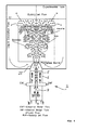
- a bubbly-jet injector as presented in Figure 1 was developed after a series of calculations and experiments had been carried out in order to determine the optimal configuration of the different tubes 6, 8 and needles 4 for forming bubbles with uniform size in the range between 1 and 6 mm in co-currently upward-flowing liquid.
- bubbles are formed by continuously injecting as a first fluid flow an air flow AF through needles 4 into the co-currently flowing water IWF(i.e. internal liquid flow or second fluid flow).
- the jet flow is formed afterwards by adding an external liquid flow EWF (as the third fluid flow).
- EWF an external liquid flow
- FIG. 1 A suitable tube-needle configuration that avoids unstable bubble formation using the needles 4 as first tubes in the sense of the claim language is shown in Figure 1.
- the bubbly-jet injector 2 comprises three chambers 10, 12, 14 for, from bottom to top, an air injection chamber 10 injecting air through the (hypodermic) needles 4 for generating the air flow AF, a lower water injection chamber 12 injecting water into the tubes 8 for generating the inner water flow IWF and an upper water injection chamber 14 injecting water into the space limited by the outer surface of the tubes 8 and the inner surface of the tube 6 for generating the external or outer water flow EWF.
- the nozzle 20 on top shown as a cylindrical version, can be exchanged against others with different shape.
- the air injection chamber 10 is sealed against the lower water injection chamber 12 by separation plate 16, i.e. a tube sheet in which the air injection needles are fixed.
- separation plate 16 i.e. a tube sheet in which the air injection needles are fixed.
- Another partition plate 18 separates the lower water injection chamber 12 from the upper water injection chamber 14.
- the considerations made above show that the basic adjustable parameters are jet diameter, internal and external liquid flow rate and gas flow rate.
- the basic parts of the injector that can be exchanged are:
- the operating parameters are chosen in such a way that the relative size of the different forces acting on the bubbles and the related non-dimensional groups can be varied. Furthermore, one of the main objectives of this system design is also to generate coherent structures in the jet flow and to determine their influence and role on bubble movement. The performance of heat and mass transfer equipment in industrial application is strongly related to these flow properties.
- C Fr , Cr and C St are also dimensionless and can be expressed by a Bubble Re number, a Bubble Fr number and the relative size of the bubbles ⁇ .
- the terminal bubble velocity ( V T ) in still fluid is a function of the bubble diameter and the physical properties of the fluid.
- the terminal rise velocity of a single bubble or the Bubble Reynolds number Re T and the corresponding friction coefficient C dT can be expressed as a function of these dimensionless numbers.
- Variation of the parameter ⁇ also changes the ratio between shear-induced and bubble-induced turbulence in the jet. Different jet sizes are used for the following reasons:
- Fr and r can be varied during the experiment typically extend from about 0.1 to 10 and that of St from 0.001 to 1.
- the (homogeneous) void fraction ⁇ h Q G /(Q L +Q G ) determines void feedback and together with the bubble size, also bubble interaction.
- the results show that for high Re jet and bubble diameters only small void fractions can be produced.
- higher void fractions can always be obtained (also for large Re jet ) numbers by further increasing the gas flow rate if bubble-size uniformity is not required. Even for such high gas flow rate, varying the internal liquid flow rate can also change the mean bubble size. Bubbly flows having high void fractions and containing a wider range of bubble sizes can be considered as possible operating conditions.
Priority Applications (4)
| Application Number | Priority Date | Filing Date | Title |
|---|---|---|---|
| EP04008712A EP1586369A1 (fr) | 2004-04-13 | 2004-04-13 | Appareillage pour générer des bulles fines de gaz dans un liquide |
| EP05716096A EP1740301B1 (fr) | 2004-04-13 | 2005-03-16 | Appareillage pour generer des bulles fines de gaz dans un liquide |
| AT05716096T ATE535303T1 (de) | 2004-04-13 | 2005-03-16 | Vorrichtung zur erzeugung von feinen gasbläschen in einer flüssigkeit |
| PCT/EP2005/002770 WO2005099888A1 (fr) | 2004-04-13 | 2005-03-16 | Appareil permettant de produire de fines bulles de gaz dans un liquide |
Applications Claiming Priority (1)
| Application Number | Priority Date | Filing Date | Title |
|---|---|---|---|
| EP04008712A EP1586369A1 (fr) | 2004-04-13 | 2004-04-13 | Appareillage pour générer des bulles fines de gaz dans un liquide |
Publications (1)
| Publication Number | Publication Date |
|---|---|
| EP1586369A1 true EP1586369A1 (fr) | 2005-10-19 |
Family
ID=34924578
Family Applications (2)
| Application Number | Title | Priority Date | Filing Date |
|---|---|---|---|
| EP04008712A Withdrawn EP1586369A1 (fr) | 2004-04-13 | 2004-04-13 | Appareillage pour générer des bulles fines de gaz dans un liquide |
| EP05716096A Not-in-force EP1740301B1 (fr) | 2004-04-13 | 2005-03-16 | Appareillage pour generer des bulles fines de gaz dans un liquide |
Family Applications After (1)
| Application Number | Title | Priority Date | Filing Date |
|---|---|---|---|
| EP05716096A Not-in-force EP1740301B1 (fr) | 2004-04-13 | 2005-03-16 | Appareillage pour generer des bulles fines de gaz dans un liquide |
Country Status (3)
| Country | Link |
|---|---|
| EP (2) | EP1586369A1 (fr) |
| AT (1) | ATE535303T1 (fr) |
| WO (1) | WO2005099888A1 (fr) |
Cited By (3)
| Publication number | Priority date | Publication date | Assignee | Title |
|---|---|---|---|---|
| EP2153884A1 (fr) * | 2008-08-15 | 2010-02-17 | Air Products and Chemicals, Inc. | Procédé et dispositif d'approvisionnement de gaz |
| CN109847658A (zh) * | 2019-03-21 | 2019-06-07 | 中国科学院上海高等研究院 | 浆态床反应器及反应方法 |
| CN113058507A (zh) * | 2021-04-02 | 2021-07-02 | 唐山开滦化工科技有限公司 | 一种聚甲醛终止剂的加入装置及方法 |
Families Citing this family (12)
| Publication number | Priority date | Publication date | Assignee | Title |
|---|---|---|---|---|
| US9854715B2 (en) | 2011-06-27 | 2017-12-26 | Ebullient, Inc. | Flexible two-phase cooling system |
| US9901013B2 (en) | 2011-06-27 | 2018-02-20 | Ebullient, Inc. | Method of cooling series-connected heat sink modules |
| US9901008B2 (en) | 2014-10-27 | 2018-02-20 | Ebullient, Inc. | Redundant heat sink module |
| US9832913B2 (en) | 2011-06-27 | 2017-11-28 | Ebullient, Inc. | Method of operating a cooling apparatus to provide stable two-phase flow |
| US9848509B2 (en) | 2011-06-27 | 2017-12-19 | Ebullient, Inc. | Heat sink module |
| US9854714B2 (en) | 2011-06-27 | 2017-12-26 | Ebullient, Inc. | Method of absorbing sensible and latent heat with series-connected heat sinks |
| US10184699B2 (en) | 2014-10-27 | 2019-01-22 | Ebullient, Inc. | Fluid distribution unit for two-phase cooling system |
| US9852963B2 (en) | 2014-10-27 | 2017-12-26 | Ebullient, Inc. | Microprocessor assembly adapted for fluid cooling |
| AU2015339746A1 (en) * | 2014-10-27 | 2017-06-15 | Ebullient, Llc | Method of condensing vapor in a two-phase cooling system |
| US9891002B2 (en) | 2014-10-27 | 2018-02-13 | Ebullient, Llc | Heat exchanger with interconnected fluid transfer members |
| US20160120059A1 (en) | 2014-10-27 | 2016-04-28 | Ebullient, Llc | Two-phase cooling system |
| CN109316994B (zh) * | 2018-11-01 | 2021-06-18 | 中国海洋石油集团有限公司 | 一种高浓度聚合物溶液的稀释方法 |
Citations (4)
| Publication number | Priority date | Publication date | Assignee | Title |
|---|---|---|---|---|
| EP0218253A2 (fr) * | 1985-10-11 | 1987-04-15 | Mitsubishi Rayon Engineering Co., Ltd. | Procédé et aérateur pour le traitement biologique aérobie |
| EP0323646A2 (fr) * | 1987-12-30 | 1989-07-12 | Praxair Technology, Inc. | Procédé de séparation d'un composant ayant une pression de vapeur élevée et/ou une substance particulière d'un composant ayant une pression de vapeur basse |
| WO2001097958A1 (fr) * | 2000-06-23 | 2001-12-27 | Ikeda, Yoshiaki | Generateur de bulles d'air fines et dispositif de generation de bulles d'air fines muni de ce generateur |
| WO2002006167A1 (fr) * | 2000-07-18 | 2002-01-24 | Williams, Thomas, G | Systeme de buse |
-
2004
- 2004-04-13 EP EP04008712A patent/EP1586369A1/fr not_active Withdrawn
-
2005
- 2005-03-16 EP EP05716096A patent/EP1740301B1/fr not_active Not-in-force
- 2005-03-16 WO PCT/EP2005/002770 patent/WO2005099888A1/fr active Application Filing
- 2005-03-16 AT AT05716096T patent/ATE535303T1/de active
Patent Citations (4)
| Publication number | Priority date | Publication date | Assignee | Title |
|---|---|---|---|---|
| EP0218253A2 (fr) * | 1985-10-11 | 1987-04-15 | Mitsubishi Rayon Engineering Co., Ltd. | Procédé et aérateur pour le traitement biologique aérobie |
| EP0323646A2 (fr) * | 1987-12-30 | 1989-07-12 | Praxair Technology, Inc. | Procédé de séparation d'un composant ayant une pression de vapeur élevée et/ou une substance particulière d'un composant ayant une pression de vapeur basse |
| WO2001097958A1 (fr) * | 2000-06-23 | 2001-12-27 | Ikeda, Yoshiaki | Generateur de bulles d'air fines et dispositif de generation de bulles d'air fines muni de ce generateur |
| WO2002006167A1 (fr) * | 2000-07-18 | 2002-01-24 | Williams, Thomas, G | Systeme de buse |
Cited By (5)
| Publication number | Priority date | Publication date | Assignee | Title |
|---|---|---|---|---|
| EP2153884A1 (fr) * | 2008-08-15 | 2010-02-17 | Air Products and Chemicals, Inc. | Procédé et dispositif d'approvisionnement de gaz |
| WO2010018014A1 (fr) * | 2008-08-15 | 2010-02-18 | Air Products And Chemicals, Inc. | Procédé et appareil pour la délivrance d’un gaz |
| CN109847658A (zh) * | 2019-03-21 | 2019-06-07 | 中国科学院上海高等研究院 | 浆态床反应器及反应方法 |
| CN109847658B (zh) * | 2019-03-21 | 2021-07-30 | 中国科学院上海高等研究院 | 浆态床反应器及反应方法 |
| CN113058507A (zh) * | 2021-04-02 | 2021-07-02 | 唐山开滦化工科技有限公司 | 一种聚甲醛终止剂的加入装置及方法 |
Also Published As
| Publication number | Publication date |
|---|---|
| WO2005099888A1 (fr) | 2005-10-27 |
| EP1740301B1 (fr) | 2011-11-30 |
| ATE535303T1 (de) | 2011-12-15 |
| EP1740301A1 (fr) | 2007-01-10 |
Similar Documents
| Publication | Publication Date | Title |
|---|---|---|
| EP1740301B1 (fr) | Appareillage pour generer des bulles fines de gaz dans un liquide | |
| US8529026B2 (en) | Droplet generator | |
| Fu et al. | Bubble formation and breakup dynamics in microfluidic devices: A review | |
| US5810052A (en) | Method of obtaining a free disperse system in liquid and device for effecting the same | |
| US5492654A (en) | Method of obtaining free disperse system and device for effecting same | |
| EP1359997B1 (fr) | Appareil et procede de creation de cavitation hydrodynamique dans des fluides | |
| Ganán-Calvo et al. | Perfectly monodisperse microbubbling by capillary flow focusing | |
| CA2320450C (fr) | Procede et appareil pour l'obtention de systemes de dispersion liquide | |
| RU2468857C2 (ru) | Устройство для смешения потоков текучей среды (варианты) | |
| JP2010530804A (ja) | 触媒床上で液相及び気相の三相反応を実行するための反応器 | |
| Xie et al. | Preparation of microbubbles with the generation of Dean vortices in a porous membrane | |
| Irandoust et al. | Scaling up of a monolithic catalyst reactor with two-phase flow | |
| NL8001880A (nl) | Emulgeerinrichting. | |
| Briens et al. | Hydrodynamics and gas-liquid mass transfer in a downward venturi-bubble column combination | |
| CA2056418A1 (fr) | Appareil servant a disperser un gaz pour agiter un liquide et methode connexe | |
| Nedeltchev et al. | A fundamental approach to bubble column scale-up based on quality of mixedness | |
| EP1501626B1 (fr) | Dispositif et procede de creation de cavitation hydrodynamique dans des fluides | |
| RU2718617C1 (ru) | Микродиспергатор для генерирования капель | |
| US20060231963A1 (en) | Method and apparatus for producing fine particles | |
| EP1846144B1 (fr) | Dispositif permettant de produire une surface de limite de phase aussi grande que possible pour le melange continu et a haut rendement de differents fluides dans des melanges gaz-liquide | |
| Gopal et al. | Hydrodynamic and mass transfer characteristics of bubble and packed bubble columns with downcomer | |
| RU2732142C1 (ru) | Микродиспергатор с периодической структурой с переменным шагом для генерирования капель | |
| Shen et al. | Transition from bubbling to jetting in submerged gas-liquid jets through a minichannel | |
| Drenckhan et al. | Foam Formation Techniques | |
| Mu et al. | Active control on droplet generation in axisymmetric flow focusing |
Legal Events
| Date | Code | Title | Description |
|---|---|---|---|
| PUAI | Public reference made under article 153(3) epc to a published international application that has entered the european phase |
Free format text: ORIGINAL CODE: 0009012 |
|
| AK | Designated contracting states |
Kind code of ref document: A1 Designated state(s): AT BE BG CH CY CZ DE DK EE ES FI FR GB GR HU IE IT LI LU MC NL PL PT RO SE SI SK TR |
|
| AX | Request for extension of the european patent |
Extension state: AL HR LT LV MK |
|
| AKX | Designation fees paid | ||
| REG | Reference to a national code |
Ref country code: DE Ref legal event code: 8566 |
|
| STAA | Information on the status of an ep patent application or granted ep patent |
Free format text: STATUS: THE APPLICATION IS DEEMED TO BE WITHDRAWN |
|
| 18D | Application deemed to be withdrawn |
Effective date: 20060420 |