EP1586340B1 - Breast pump - Google Patents
Breast pump Download PDFInfo
- Publication number
- EP1586340B1 EP1586340B1 EP05252269A EP05252269A EP1586340B1 EP 1586340 B1 EP1586340 B1 EP 1586340B1 EP 05252269 A EP05252269 A EP 05252269A EP 05252269 A EP05252269 A EP 05252269A EP 1586340 B1 EP1586340 B1 EP 1586340B1
- Authority
- EP
- European Patent Office
- Prior art keywords
- breast pump
- pump according
- motor
- valve
- milk
- Prior art date
- Legal status (The legal status is an assumption and is not a legal conclusion. Google has not performed a legal analysis and makes no representation as to the accuracy of the status listed.)
- Not-in-force
Links
Images


Classifications
-
- A—HUMAN NECESSITIES
- A61—MEDICAL OR VETERINARY SCIENCE; HYGIENE
- A61M—DEVICES FOR INTRODUCING MEDIA INTO, OR ONTO, THE BODY; DEVICES FOR TRANSDUCING BODY MEDIA OR FOR TAKING MEDIA FROM THE BODY; DEVICES FOR PRODUCING OR ENDING SLEEP OR STUPOR
- A61M1/00—Suction or pumping devices for medical purposes; Devices for carrying-off, for treatment of, or for carrying-over, body-liquids; Drainage systems
- A61M1/06—Milking pumps
- A61M1/062—Pump accessories
- A61M1/064—Suction cups
- A61M1/066—Inserts therefor
-
- A—HUMAN NECESSITIES
- A61—MEDICAL OR VETERINARY SCIENCE; HYGIENE
- A61M—DEVICES FOR INTRODUCING MEDIA INTO, OR ONTO, THE BODY; DEVICES FOR TRANSDUCING BODY MEDIA OR FOR TAKING MEDIA FROM THE BODY; DEVICES FOR PRODUCING OR ENDING SLEEP OR STUPOR
- A61M1/00—Suction or pumping devices for medical purposes; Devices for carrying-off, for treatment of, or for carrying-over, body-liquids; Drainage systems
- A61M1/06—Milking pumps
- A61M1/062—Pump accessories
- A61M1/064—Suction cups
-
- A—HUMAN NECESSITIES
- A61—MEDICAL OR VETERINARY SCIENCE; HYGIENE
- A61M—DEVICES FOR INTRODUCING MEDIA INTO, OR ONTO, THE BODY; DEVICES FOR TRANSDUCING BODY MEDIA OR FOR TAKING MEDIA FROM THE BODY; DEVICES FOR PRODUCING OR ENDING SLEEP OR STUPOR
- A61M1/00—Suction or pumping devices for medical purposes; Devices for carrying-off, for treatment of, or for carrying-over, body-liquids; Drainage systems
- A61M1/06—Milking pumps
- A61M1/069—Means for improving milking yield
- A61M1/0693—Means for improving milking yield with programmable or pre-programmed sucking patterns
- A61M1/06935—Means for improving milking yield with programmable or pre-programmed sucking patterns imitating the suckling of an infant
-
- A—HUMAN NECESSITIES
- A61—MEDICAL OR VETERINARY SCIENCE; HYGIENE
- A61M—DEVICES FOR INTRODUCING MEDIA INTO, OR ONTO, THE BODY; DEVICES FOR TRANSDUCING BODY MEDIA OR FOR TAKING MEDIA FROM THE BODY; DEVICES FOR PRODUCING OR ENDING SLEEP OR STUPOR
- A61M1/00—Suction or pumping devices for medical purposes; Devices for carrying-off, for treatment of, or for carrying-over, body-liquids; Drainage systems
- A61M1/06—Milking pumps
- A61M1/069—Means for improving milking yield
- A61M1/0697—Means for improving milking yield having means for massaging the breast
-
- A—HUMAN NECESSITIES
- A61—MEDICAL OR VETERINARY SCIENCE; HYGIENE
- A61M—DEVICES FOR INTRODUCING MEDIA INTO, OR ONTO, THE BODY; DEVICES FOR TRANSDUCING BODY MEDIA OR FOR TAKING MEDIA FROM THE BODY; DEVICES FOR PRODUCING OR ENDING SLEEP OR STUPOR
- A61M1/00—Suction or pumping devices for medical purposes; Devices for carrying-off, for treatment of, or for carrying-over, body-liquids; Drainage systems
- A61M1/71—Suction drainage systems
- A61M1/73—Suction drainage systems comprising sensors or indicators for physical values
- A61M1/734—Visual indicating means for flow
-
- A—HUMAN NECESSITIES
- A61—MEDICAL OR VETERINARY SCIENCE; HYGIENE
- A61M—DEVICES FOR INTRODUCING MEDIA INTO, OR ONTO, THE BODY; DEVICES FOR TRANSDUCING BODY MEDIA OR FOR TAKING MEDIA FROM THE BODY; DEVICES FOR PRODUCING OR ENDING SLEEP OR STUPOR
- A61M1/00—Suction or pumping devices for medical purposes; Devices for carrying-off, for treatment of, or for carrying-over, body-liquids; Drainage systems
- A61M1/71—Suction drainage systems
- A61M1/74—Suction control
- A61M1/75—Intermittent or pulsating suction
-
- A—HUMAN NECESSITIES
- A61—MEDICAL OR VETERINARY SCIENCE; HYGIENE
- A61M—DEVICES FOR INTRODUCING MEDIA INTO, OR ONTO, THE BODY; DEVICES FOR TRANSDUCING BODY MEDIA OR FOR TAKING MEDIA FROM THE BODY; DEVICES FOR PRODUCING OR ENDING SLEEP OR STUPOR
- A61M2205/00—General characteristics of the apparatus
- A61M2205/33—Controlling, regulating or measuring
- A61M2205/3379—Masses, volumes, levels of fluids in reservoirs, flow rates
- A61M2205/3396—Reservoirs being alternately filled and emptied for measuring flow rate or delivered volume
-
- A—HUMAN NECESSITIES
- A61—MEDICAL OR VETERINARY SCIENCE; HYGIENE
- A61M—DEVICES FOR INTRODUCING MEDIA INTO, OR ONTO, THE BODY; DEVICES FOR TRANSDUCING BODY MEDIA OR FOR TAKING MEDIA FROM THE BODY; DEVICES FOR PRODUCING OR ENDING SLEEP OR STUPOR
- A61M2205/00—General characteristics of the apparatus
- A61M2205/50—General characteristics of the apparatus with microprocessors or computers
-
- A—HUMAN NECESSITIES
- A61—MEDICAL OR VETERINARY SCIENCE; HYGIENE
- A61M—DEVICES FOR INTRODUCING MEDIA INTO, OR ONTO, THE BODY; DEVICES FOR TRANSDUCING BODY MEDIA OR FOR TAKING MEDIA FROM THE BODY; DEVICES FOR PRODUCING OR ENDING SLEEP OR STUPOR
- A61M2205/00—General characteristics of the apparatus
- A61M2205/80—General characteristics of the apparatus voice-operated command
-
- A—HUMAN NECESSITIES
- A61—MEDICAL OR VETERINARY SCIENCE; HYGIENE
- A61M—DEVICES FOR INTRODUCING MEDIA INTO, OR ONTO, THE BODY; DEVICES FOR TRANSDUCING BODY MEDIA OR FOR TAKING MEDIA FROM THE BODY; DEVICES FOR PRODUCING OR ENDING SLEEP OR STUPOR
- A61M2205/00—General characteristics of the apparatus
- A61M2205/82—Internal energy supply devices
- A61M2205/8206—Internal energy supply devices battery-operated
Definitions
- This invention relates to a breast pump and, in particular, an electrically operated breast pump for drawing milk from a user.
- a user may, with some existing breast pumps, be able to adjust the pumping cycles, e.g. by varying the number of suction cycles per minute, or adjusting the vacuum level for pumping milk from the user's breast, it is up to the user to decide whether to make such variation or adjustment, and the user may simply have no information on which to decide whether the current pumping rate is suitable or not
- US Patent No. 6,547,756 issued to Greter et aL discloses a programmable breast pump which may be programmed to generate a number of different milk expression (extraction) sequences, or curves.
- a motorized pump is provided with a microprocessor-based controller.
- an electric breast pump as defined in the claims.
- Figs. 1 and 2 show an electrically operated breast pump according to a preferred embodiment of the present invention, generally designated as 10.
- the breast pump 10 has a hood 12 adapted to be fitted over a breast of a user in an essentially gas-tight manner, for pumping milk from the breast.
- An insert 12a for contacting the user's breast is received within the hood 12.
- the insert 12a is made of a soft plastic material, e.g. silicone, to provide comfort to the user during use.
- the hood 12 is in funnel shape and has a tunnel 14 leading to a connector 16, which fluidly communicates with the hood 12, and with a milk-receiving bottle 18 via a valve seat 20, the structure and function of which will be further discussed below.
- the connector 16 is engaged with a head portion 22 which houses most of the operating components of the breast pump 10, as will be clear from the ensuing discussion.
- a head portion 22 which houses most of the operating components of the breast pump 10, as will be clear from the ensuing discussion.
- On a top surface 24 of the head portion 22 is provided with an ON/OFF button 26 for selectively activating/deactivating the breast pump 10.
- Also provided on the top surface 24 of the head portion 22 is a liquid crystal display (LCD) 28 for displaying various operation information and data relating to the operation of the breast pump 10.
- the head portion 22 is connected with a handle 30, which also acts as a battery compartment for housing a number of batteries 32 for powering the breast pump 10.
- the handle 30 is swivellable relative to the head portion 22 for easy handling.
- a PAUSE button 34 On each side of the handle 30 is provided a PAUSE button 34, allowing a user to temporarily suspend the operation of the breast pump 10 by pressing the button 34 once, and to resume its operation by pressing the button 34 once again.
- a power jack 36 On a side of the head portion 22 is a power jack 36 which allows the breast pump 10 to be powered by an A/C source, possibly via a transformer (not shown).
- Fig. 3 shows a sectional view of the breast pump 10.
- IR infrared
- a pump motor 42 for operating a pump diaphragm 44 for generating a low pressure (vacuum) in the breast pump 10.
- a valve motor 46 for operating a needle valve 48.
- the valve 48 is pneumatically connected, e.g. via a hose (not shown), with a nozzle 50 which is in turn pneumatically connected with the milk-receiving bottle 18.
- a microcontroller 40 for controlling the operation of various electronic and electrical components of the breast pump 10.
- the microcontrolller 40 is electrically connected with and controls the operation of the pump motor 42, the valve motor 46, and the LCD display 28.
- the microcontroller 40 is also connected with and receives instructions and/or signals from the PAUSE buttons 34 and the IR units 38a, 38b.
- Fig. 6 shows in more detail a circuitry which controls the operation of the valve motor 46, the pump motor 42, and the IR units 38a, 38b, of which only one set 38a is shown here.
- Fig. 7 shows the setting of the LCD display 28, and it can be seen that the LCD display 28 may display such information as the setting being used, the flow-rate (slow, medium, high), battery low, and the remaining time (in minutes) required for filling the bottle 18.
- a microcontroller 40 suitable for use in the breast pump 10 may be one traded by Sino Wealth Microelectronics Corporation Limited, of Hong Kong, under serial number SH6622A, although other similar microcontrollers may also be used.
- SH6622A is a 4-bit microcontroller, which integrates a 4-bit CPU core with SRAM, 4K program ROM, timer and I/O Port Fig. 8 shows a block diagram of SH6622A.
- the CPU of SH6622A contains the following function blocks: Program Counter, Arithmetic Logic Unit (ALU), Carry Flag, Accumulator, Table Branch Register, Data Pointer (INX, DPH, DPM, and DPL), and Stack.
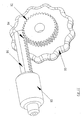
- Fig. 9 shows an enlarged perspective view of the pump motor 42, having an output spindle 51 engaged with an eccentric cam 52 which in turn carries a yoke 54 fixed with the pump diaphragm 44.
- rotational movement of the output pin 51 is converted into linear reciprocal movement of the diaphragm 44 in the direction of the bi-directional arrow L-L.
- a linkage mechanism 58 comprising six links 60 linked with one another in a hexagonal ring-shaped structure. Each link 60 is swivellable relative to two adjacent links 60 to which it is pivotally hinged. Over the output spindle 51 is also provided with a spring 62 which biases an end pin 64 outwardly, which in turn acts on and biases a lid 66 away from a vent hole 68.
- the diaphragm 44 is positioned in a chamber 71 which is closeable by the lid 66, a first one-way valve 70, and a second one-way valve 74.
- the first one-way valve 70 only allows air to enter the chamber 71 from a conduit 72, which is in turn in fluid communication with the hood 12.
- the second one-way valve 74 only allows air to exit the chamber 71.
- the linkage mechanism 58 When the motor 42 is not in operation, the linkage mechanism 58 will be biased by the spring 62 to assume the shape and configuration as shown in Figs. 3 and 10 .
- rotation of the output spindle 51 will bring about simultaneous and corresponding rotation of the linkage mechanism 58, whereby the hexagonal ring-shaped structure 58 will "flatten” because of the centrifugal force generated by the rotation, thus retracting the end pin 64 against the outward biasing force of the spring 62.
- the lid 66 will thus close the vent hole 68.
- the manual pressure adjustment mechanism includes a wheel 80 with a gear 82 in mesh with a pinion 84 on an end of a pin 86 and a valve seat 88.
- the wheel 80 is fixed to the handle 30 for rotational movement. The wheel 80 may be moved by a thumb of a user to rotate relative to the handle 30, about the longitudinal axis of the wheel 80.
- the valve seat 88 is also fixedly secured to the handle 30.
- the valve seat 88 is made of a thermoplastic elastomer (TPE) or silicone, and when the pin 86 is fully received within the recess 90, the valve seat 88 is fully sealed, whereas air may enter the valve seat 88 if the pin 86 is retrieved from the valve seat 88, and the amount of air allowed to enter the valve seat 88 will depend on the extent to which the pin 86 is retrieved from the valve seat 88.
- the recess 90 is in fluid communication with a nozzle 92, which is in turn in fluid communication with the hood 12, e.g. via a hose (not shown) connected to the conduit 72, so that the pressure within the hood 12 when such is applied over a breast of a user may be fine-tuned by the user by manually operating the wheel 80.
- the pump diaphragm 44 When the breast pump 10 is fitted over a breast of a user and the pump motor 42 is activated, the pump diaphragm 44 will reciprocate to generate a lower pressure ("vacuum") in the hood 12, thus stimulating milk ejection reflex and subsequent expression of milk. Milk from the breast of the user will flow into the hood 12 and subsequently into the chamber 3 7 in the direction of the arrow M. The milk will accumulate in the chamber 37, first blocking the transmission of infrared signals between the transmitter and receiver of the lower IR unit 38a, and subsequently that between the transmitter and receiver of the upper IR unit 38b.
- valve seat 20 In the valve seat 20 is a one-way valve 96 which allows milk to enter the bottle 18, but not vice versa . Because the hood 12 is at a lower pressure than the bottle 18 during operation of the pumping action of the diaphragm 44, the higher pressure in the bottle 18 will prevent the milk in the chamber 37 from entering the bottle 18, thus allowing the milk level to rise in the chamber 37. It may take several sucking/releasing cycles before the milk level rises to, and blocks the transmission of infrared signals between the transmitter and receiver of, the upper IR unit 38b. When the milk level rises to the upper IR unit 38b, the motor 42 will stop, thus releasing the "vacuum" in the hood 12, in the manner discussed above.
- the needle valve 48 will be opened by the valve motor 46, whereby air will exit the bottle 18 via the nozzle 50, and subsequently out of the needle valve 48.
- the milk in the chamber 37 will thus fall, on its own weight, through the one-way valve 96 into the bottle 18, during the course of which the level of milk in the chamber 37 will fall.
- the transmission of IR signals between the transmitter and receiver of the upper IR unit 38b will thus resume, and then that between the transmitter and receiver of the lower IR unit 38a will resume.
- a partition 98 which prevents milk from entering the interior of the head portion 22, e.g. when the breast pump 10 is accidentally knocked over. Milk entering the interior of the head portion 22 may damage the movement parts of the breast pump 10, thus shortening its useful life, or necessitating servicing.
- a baby's feeding is not a single continuous process, but rather a two-phased process in which the baby will initially suckle rapidly, called “stimulation”.
- stimulation Once the breast has been sufficiently stimulated, milk begins flowing and the baby will settle into a slower, more relaxed sucking speed for the actual feeding phase, called “expression”.
- the breast pump 10 can mimie the natural feeding pattern of a baby by first exhibiting rapid sucking/releasing actions to stimulate the milk ejection reflex (MER) or "let down”. Once milk begins to flow, the breast pump 10 will then exhibit slower and longer sucking/releasing actions which help to maximize milk flow in less time.
- MER milk ejection reflex
- Fig. 15 shows a flow chart of the steps of operation of the breast pump 10.
- the valve motor 46 will be triggered once to close the needle valve 48, which is called “retainer valve” in Fig. 15 (Step 102).
- a "let down" sequence will be operated in which sucking/releasing actions will be carried out at a speed of 90 cycles per minute at a pressure of 5-7 inch mercury (in Hg) for 30 seconds (Step 104).
- Step 106 If no milk flows (Step 106), an "expression" mode will be operated in which sucking/releasing actions will be carried out at a speed of 45 cycles per minute at a pressure of 7-9 in Hg for 30 seconds (Step 108). If there is still no milk flow (Step 110), the microcontroller 40 of the breast pump 10 (hereinafter simply referred to as the "breast pump 10" for simplicity) will determine if this is the first time such occurs since the breast pump 10 is started (Step 112). If not, the breast pump 10 will repeat the above process (Step 114) by carrying out the "let down" sequence again (Step 104). If, however, such a situation has already occurred once in this operation, a sign or symbol alerting the user to seek medical assistance, e.g.
- the pump motor 42 may be activated for 0.8 second, then deactivated for 0.53 second, and then activated for 0.8 second, and so on.
- the breast pump 10 will then check whether transmission of IR signals in the lower IR unit 3 8a is interrupted (Step 118). If so, a timer in the microcontroller 40 will start timing (Step 120). The breast pump 10 will then check whether transmission of IR signals in the upper IR unit 38b is interrupted (Step 122). If so, the timer will stop (Step 124). Because the volume in the chamber 37 between the lower IR unit 38a and the upper IR unit 38b is known, it is possible to thus calculate the rate of flow of milk (in grams per second, g/s) and such is calculated. The valve motor 46 will be triggered once to open the needle valve 48, thus allowing milk in the chamber 37 to fall into the bottle 18. The breast pump 10 will also count the number of times of such triggers of the valve motor 46 as "X" (Step 126).
- the breast pump 10 will then check whether transmission of IR signals in the lower IR unit 38a resumes ("released") within 2.5 seconds (Step 128). If so, the valve motor 46 will be triggered once to close the needle valve 48 (Step 130). If transmission of IR signals in the lower IR unit 38a does not resume ("released") within 2.5 seconds (Step 128), or after the closing of the needle valve 48 (Step 130), the breast pump 10 will then check if transmission of IR signals in the upper IR unit 38b is still blocked in 2.5 seconds (Step 132). If so, the pump motor 42 will stop operation, and the needle valve 48 will be opened once again (Step 134).
- Step 136 If transmission of IR signals in the upper IR unit 38b is still blocked (Step 136), the pump motor 42 will stop operation again, and the needle valve 48 will be opened once again (Step 138). If transmission of IR signals in the upper IR unit 38b is still blocked (Step 140), the pump motor 42 will stop, a warning signal will be given on the LCD display 28, and the LCD display 28 will be turned off automatically in 5 minutes, (Step 142), and the operation of the breast pump 10 will also stop automatically (Step 116). Such will prevent the motor 42 from continuing operation when, e.g. the breast pump 10 accidentally topples over.
- Step 148 If transmission of IR signals in the upper IR unit 38b is not blocked after Step 132, Step 136 or Step 140, the breast pump 10 will operate according to the milk flow rate obtained in Step 126. If the flow rate is between 0.01 to 0.09 g/s (Step 144), the breast pump 10 will switch to "let down" sequence (Step 146) in which sucking/releasing action is carried out at a frequency of 90 cycles per minute at a pressure of 5-7 in Hg, and a sign or symbol indicating low flow rate will be displayed on the LCD display 28 (Step 148).
- Step 150 If the flow rate is between 0.1 to 024 g/s (Step 150), the breast pump 10 will carry out sucking/releasing action at a frequency of 45 cycles per minute at a pressure of 7-9 in Hg (Step 152), and a sign or symbol indicating medium flow rate will be displayed on the LCD display 28 (Step 154). If the flow rate is 0.25 g/s or above (Step 156), the breast pump 10 will carry out sucking/releasing action at a frequency of 38 cycles per minute at a pressure of 6-8 in Hg (Step 158), and a sign or symbol indicating high flow rate will be displayed on the LCD display 28 (Step 160).
- the bottle 18 is designed to hold 151.51g of milk, and in each cycle, the milk that enters, and is thus collected by, the bottle 18 is 1.5g.
- the breast pump 10 is able to calculate and display the remaining time required to fill the bottle 18. In this example, it normally requires 101 triggers of the valve motor 46, "X", to fill the bottle 18. Depending on the number of times, "X", the valve motor 46 has already been triggered to open the needle valve 48, the breast pump 10 can calculate the remaining time required for filling up the bottle 18 (Step 162). The remaining time required will be displayed on the LCD display 28 (Step 164).
- Step 166 If 1.5X > 151.51 (Step 166), it means that the bottle 18 is filled up, the breast pump 10 will stop (Step 116). If not, the breast pump 10 will check again if transmission of IR signals in the lower IR unit 38a is interrupted (Step 118), and the pumping action will go on again.
Abstract
Description
- This invention relates to a breast pump and, in particular, an electrically operated breast pump for drawing milk from a user.
- There are in existence a large number of electrically operated breast pumps, allowing a user, e.g. a mother, to pump milk from her breast. Various pumping mechanisms have been proposed for drawing milk from the mother's breast, including, for example, ones disclosed in
US Patent Nos. 6,045,529 and6,355,012 issued to Nüesch. Such mechanisms are generally speaking rather complicated, and thus costly to manufacture. In addition, most such mechanisms include gear trains which would generate much noise, especially when the motor is operating at a relatively high speed. - In addition, although a user may, with some existing breast pumps, be able to adjust the pumping cycles, e.g. by varying the number of suction cycles per minute, or adjusting the vacuum level for pumping milk from the user's breast, it is up to the user to decide whether to make such variation or adjustment, and the user may simply have no information on which to decide whether the current pumping rate is suitable or not In this connection,
US Patent No. 6,547,756 issued to Greter et aL discloses a programmable breast pump which may be programmed to generate a number of different milk expression (extraction) sequences, or curves. In this arrangement, a motorized pump is provided with a microprocessor-based controller. Cards, with microprocessor "chips", containing instructions for different suction curves are also included, which may be inserted into the breast pump, so that the instructions in the cards may be read and acted upon by the breast pump. However, as in the case of other adjustable breast pumps discussed above, it is still up to a user to decide whether to change the mode of pumping operation of the breast pump, and a user may not know whether an alternative, and if so which, suction curve should be applied. A further shortcoming associated with conventional electric breast pumps is that the user is provided with no information as to the time required to fill up the milk receptacle, e.g. bottle. - Such and other shortcomings discussed above are also present in breast pumps disclosed in
US Patent No. 6,673,036 issued to Britto which discloses a pump as defined in the preamble ofclaim 1 andUS Patent No. 6,090,065 issued to Giles . - It is thus an object of the present invention to provide an electric breast pump m which the aforesaid shortcomings are mitigated or at least to provide a useful alternative to the public.
- According to the present invention, there is provided an electric breast pump as defined in the claims.
- A preferred embodiment of the present invention will now be described, by way of example only, with reference to the accompanying drawings, in which:
-
Fig. 1 is a perspective view of an electric breast pump according to the present invention; -
Fig. 2 is an exploded view of the breast pump shown inFig. 1 ; -
Fig. 3 is a sectional view of the breast pump shown inFig. 1 ; -
Fig. 4 is a sectional view taken along the line A-A inFig. 3 ; -
Fig. 5 is a circuit diagram of the breast pump shown inFig. 1 ; -
Fig. 6 shows part of the circuitry in the breast pump shown inFig. 1 ; -
Fig. 7 shows a liquid crystal display (LCD) setting in the breast pump shown inFig. 1 ; -
Fig. 8 is a block diagram of an exemplary microcontroller which may be used in the circuit shown inFig. 5 ; -
Fig. 9 is an enlarged view showing the engagement between the pump motor and the diaphragm in the breast pump shown inFig. 1 ; -
Fig. 10 is an enlarged sectional view of part of the breast pump shown inFig. 3 ; -
Fig. 11 is an enlarged perspective view showing the mechanism for manual adjustment of the level of vacuum in the breast pump shown inFig. 1 ; -
Fig. 12 shows a first configuration of the manual vacuum adjustment mechanism shown inFig. 11 ; -
Fig. 13 shows a second configuration of the manual vacuum adjustment mechanism shown inFig. 11 ; -
Fig. 14 shows an enlarged sectional view of the milk flow sensing mechanism in the breast pump shown inFig. 1 ; and -
Fig. 15 is a flow chart showing the steps of operation of the breast pump shown inFig. 1 . -
Figs. 1 and2 show an electrically operated breast pump according to a preferred embodiment of the present invention, generally designated as 10. Thebreast pump 10 has ahood 12 adapted to be fitted over a breast of a user in an essentially gas-tight manner, for pumping milk from the breast. Aninsert 12a for contacting the user's breast is received within thehood 12. Theinsert 12a is made of a soft plastic material, e.g. silicone, to provide comfort to the user during use. Thehood 12 is in funnel shape and has atunnel 14 leading to aconnector 16, which fluidly communicates with thehood 12, and with a milk-receivingbottle 18 via avalve seat 20, the structure and function of which will be further discussed below. - The
connector 16 is engaged with ahead portion 22 which houses most of the operating components of thebreast pump 10, as will be clear from the ensuing discussion. On atop surface 24 of thehead portion 22 is provided with an ON/OFF button 26 for selectively activating/deactivating thebreast pump 10. Also provided on thetop surface 24 of thehead portion 22 is a liquid crystal display (LCD) 28 for displaying various operation information and data relating to the operation of thebreast pump 10. Thehead portion 22 is connected with ahandle 30, which also acts as a battery compartment for housing a number ofbatteries 32 for powering thebreast pump 10. Thehandle 30 is swivellable relative to thehead portion 22 for easy handling. On each side of thehandle 30 is provided aPAUSE button 34, allowing a user to temporarily suspend the operation of thebreast pump 10 by pressing thebutton 34 once, and to resume its operation by pressing thebutton 34 once again. On a side of thehead portion 22 is apower jack 36 which allows thebreast pump 10 to be powered by an A/C source, possibly via a transformer (not shown). -
Fig. 3 shows a sectional view of thebreast pump 10. As shown inFig. 3 , provided in achamber 37 of theconnector 16 are two infrared (IR)units head portion 22 is apump motor 42 for operating apump diaphragm 44 for generating a low pressure (vacuum) in thebreast pump 10. Within thehandle 30 is avalve motor 46 for operating aneedle valve 48. Thevalve 48 is pneumatically connected, e.g. via a hose (not shown), with anozzle 50 which is in turn pneumatically connected with the milk-receivingbottle 18. - Housed in the
head portion 22 is amicrocontroller 40 for controlling the operation of various electronic and electrical components of thebreast pump 10. As shown inFig. 5 , themicrocontrolller 40 is electrically connected with and controls the operation of thepump motor 42, thevalve motor 46, and theLCD display 28. Themicrocontroller 40 is also connected with and receives instructions and/or signals from thePAUSE buttons 34 and theIR units Fig. 6 shows in more detail a circuitry which controls the operation of thevalve motor 46, thepump motor 42, and theIR units set 38a is shown here. -
Fig. 7 shows the setting of theLCD display 28, and it can be seen that theLCD display 28 may display such information as the setting being used, the flow-rate (slow, medium, high), battery low, and the remaining time (in minutes) required for filling thebottle 18. - A
microcontroller 40 suitable for use in thebreast pump 10 may be one traded by Sino Wealth Microelectronics Corporation Limited, of Hong Kong, under serial number SH6622A, although other similar microcontrollers may also be used. SH6622A is a 4-bit microcontroller, which integrates a 4-bit CPU core with SRAM, 4K program ROM, timer and I/O PortFig. 8 shows a block diagram of SH6622A. The CPU of SH6622A contains the following function blocks: Program Counter, Arithmetic Logic Unit (ALU), Carry Flag, Accumulator, Table Branch Register, Data Pointer (INX, DPH, DPM, and DPL), and Stack. -
Fig. 9 shows an enlarged perspective view of thepump motor 42, having anoutput spindle 51 engaged with aneccentric cam 52 which in turn carries ayoke 54 fixed with thepump diaphragm 44. By way of such an arrangement, rotational movement of theoutput pin 51 is converted into linear reciprocal movement of thediaphragm 44 in the direction of the bi-directional arrow L-L. - As can be clearly seen in
Fig. 10 , fixed to theoutput spindle 51 of thepump motor 42 is alinkage mechanism 58 comprising sixlinks 60 linked with one another in a hexagonal ring-shaped structure. Eachlink 60 is swivellable relative to twoadjacent links 60 to which it is pivotally hinged. Over theoutput spindle 51 is also provided with aspring 62 which biases anend pin 64 outwardly, which in turn acts on and biases alid 66 away from avent hole 68. Thediaphragm 44 is positioned in achamber 71 which is closeable by thelid 66, a first one-way valve 70, and a second one-way valve 74. The first one-way valve 70 only allows air to enter thechamber 71 from aconduit 72, which is in turn in fluid communication with thehood 12. The second one-way valve 74 only allows air to exit thechamber 71. - When the
motor 42 is not in operation, thelinkage mechanism 58 will be biased by thespring 62 to assume the shape and configuration as shown inFigs. 3 and10 . During operation of thepump motor 42, rotation of theoutput spindle 51 will bring about simultaneous and corresponding rotation of thelinkage mechanism 58, whereby the hexagonal ring-shapedstructure 58 will "flatten" because of the centrifugal force generated by the rotation, thus retracting theend pin 64 against the outward biasing force of thespring 62. Thelid 66 will thus close thevent hole 68. With thevent hole 68 closed by thelid 66, linear reciprocal movement of thediaphragm 44 in the direction of the bi-directional arrow L-L will draw air from thehood 12, through theconduit 72 and the first one-way valve 70, into thechamber 71, and push the air out through the second one-way valve 74, thus generating a lower pressure ("vacuum") in thehood 12 relative to the outside atmospheric pressure, and mimicking a sucking action of a baby on a mother's breast. The sucking/releasing cycle is completed by a releasing action when themotor 42 stops rotation. Upon stopping of themotor 42, thelinkage mechanism 58 will, under the biasing force of thespring 62, resume the stable shape and configuration as shown inFigs. 3 and10 , whereupon thelid 66 will be pushed by theend pin 64 away from thevent hole 68, to thereby open thevent hole 68. When thevent hole 68 is opened, air will enter thevent hole 68, and then back into thehood 12, thus releasing the "vacuum" in thehood 12. - To allow further versatility of the
breast pump 10, a manual pressure adjustment mechanism is provided, allowing the user to manually adjust the level of "vacuum" applied during operation of thebreast pump 10, to suit individual need in different times. As shown inFig. 11 , the manual pressure adjustment mechanism includes awheel 80 with agear 82 in mesh with apinion 84 on an end of apin 86 and avalve seat 88. As can be seen inFigs. 10 ,12 and 13 , thewheel 80 is fixed to thehandle 30 for rotational movement. Thewheel 80 may be moved by a thumb of a user to rotate relative to thehandle 30, about the longitudinal axis of thewheel 80. Thevalve seat 88 is also fixedly secured to thehandle 30. Byway of such an arrangement, and because of the engagement between thegear 82 and thepinion 84, rotation of thewheel 80 will cause thepin 86 to move in or out of arecess 90 in thevalve seat 88. In particular, rotation of thewheel 80 in the direction indicated by the arrow F inFig. 12 will retrieve thepin 86 from therecess 90, whereas rotation of fhewheel 80 in the direction indicated by the arrow R inFig. 13 will insert thepin 86 further into therecess 90. - The
valve seat 88 is made of a thermoplastic elastomer (TPE) or silicone, and when thepin 86 is fully received within therecess 90, thevalve seat 88 is fully sealed, whereas air may enter thevalve seat 88 if thepin 86 is retrieved from thevalve seat 88, and the amount of air allowed to enter thevalve seat 88 will depend on the extent to which thepin 86 is retrieved from thevalve seat 88. Therecess 90 is in fluid communication with anozzle 92, which is in turn in fluid communication with thehood 12, e.g. via a hose (not shown) connected to theconduit 72, so that the pressure within thehood 12 when such is applied over a breast of a user may be fine-tuned by the user by manually operating thewheel 80. - When the
breast pump 10 is fitted over a breast of a user and thepump motor 42 is activated, thepump diaphragm 44 will reciprocate to generate a lower pressure ("vacuum") in thehood 12, thus stimulating milk ejection reflex and subsequent expression of milk. Milk from the breast of the user will flow into thehood 12 and subsequently into thechamber 3 7 in the direction of the arrow M. The milk will accumulate in thechamber 37, first blocking the transmission of infrared signals between the transmitter and receiver of thelower IR unit 38a, and subsequently that between the transmitter and receiver of theupper IR unit 38b. - In the
valve seat 20 is a one-way valve 96 which allows milk to enter thebottle 18, but not vice versa. Because thehood 12 is at a lower pressure than thebottle 18 during operation of the pumping action of thediaphragm 44, the higher pressure in thebottle 18 will prevent the milk in thechamber 37 from entering thebottle 18, thus allowing the milk level to rise in thechamber 37. It may take several sucking/releasing cycles before the milk level rises to, and blocks the transmission of infrared signals between the transmitter and receiver of, theupper IR unit 38b. When the milk level rises to theupper IR unit 38b, themotor 42 will stop, thus releasing the "vacuum" in thehood 12, in the manner discussed above. In addition, theneedle valve 48 will be opened by thevalve motor 46, whereby air will exit thebottle 18 via thenozzle 50, and subsequently out of theneedle valve 48. The milk in thechamber 37 will thus fall, on its own weight, through the one-way valve 96 into thebottle 18, during the course of which the level of milk in thechamber 37 will fall. The transmission of IR signals between the transmitter and receiver of theupper IR unit 38b will thus resume, and then that between the transmitter and receiver of thelower IR unit 38a will resume. - As shown clearly in
Figs. 4 and14 , above theupper IR unit 38b is apartition 98 which prevents milk from entering the interior of thehead portion 22, e.g. when thebreast pump 10 is accidentally knocked over. Milk entering the interior of thehead portion 22 may damage the movement parts of thebreast pump 10, thus shortening its useful life, or necessitating servicing. - Researches indicate that a baby's feeding is not a single continuous process, but rather a two-phased process in which the baby will initially suckle rapidly, called "stimulation". Once the breast has been sufficiently stimulated, milk begins flowing and the baby will settle into a slower, more relaxed sucking speed for the actual feeding phase, called "expression". The
breast pump 10 can mimie the natural feeding pattern of a baby by first exhibiting rapid sucking/releasing actions to stimulate the milk ejection reflex (MER) or "let down". Once milk begins to flow, thebreast pump 10 will then exhibit slower and longer sucking/releasing actions which help to maximize milk flow in less time. - The manner of operation of the
breast pump 10 will be further discussed by reference toFig. 15 , which shows a flow chart of the steps of operation of thebreast pump 10. Once thebreast pump 10 is started (Step 100), thevalve motor 46 will be triggered once to close theneedle valve 48, which is called "retainer valve" inFig. 15 (Step 102). A "let down" sequence will be operated in which sucking/releasing actions will be carried out at a speed of 90 cycles per minute at a pressure of 5-7 inch mercury (in Hg) for 30 seconds (Step 104). If no milk flows (Step 106), an "expression" mode will be operated in which sucking/releasing actions will be carried out at a speed of 45 cycles per minute at a pressure of 7-9 in Hg for 30 seconds (Step 108). If there is still no milk flow (Step 110), themicrocontroller 40 of the breast pump 10 (hereinafter simply referred to as the "breast pump 10" for simplicity) will determine if this is the first time such occurs since thebreast pump 10 is started (Step 112). If not, thebreast pump 10 will repeat the above process (Step 114) by carrying out the "let down" sequence again (Step 104). If, however, such a situation has already occurred once in this operation, a sign or symbol alerting the user to seek medical assistance, e.g. to undergo certain milk flow stimulation operation, will be displayed on the LCD display 28 (Step 115), and thebreast pump 10 will also cease operation immediately (Step 116). For carrying out sucking/releasing actions at a frequency of 45 cycles per minute, thepump motor 42 may be activated for 0.8 second, then deactivated for 0.53 second, and then activated for 0.8 second, and so on. - If milk flows after the "let down" sequence (Step 104) or the "expression" sequence (Step 110), the
breast pump 10 will then check whether transmission of IR signals in thelower IR unit 3 8a is interrupted (Step 118). If so, a timer in themicrocontroller 40 will start timing (Step 120). Thebreast pump 10 will then check whether transmission of IR signals in theupper IR unit 38b is interrupted (Step 122). If so, the timer will stop (Step 124). Because the volume in thechamber 37 between thelower IR unit 38a and theupper IR unit 38b is known, it is possible to thus calculate the rate of flow of milk (in grams per second, g/s) and such is calculated. Thevalve motor 46 will be triggered once to open theneedle valve 48, thus allowing milk in thechamber 37 to fall into thebottle 18. Thebreast pump 10 will also count the number of times of such triggers of thevalve motor 46 as "X" (Step 126). - The
breast pump 10 will then check whether transmission of IR signals in thelower IR unit 38a resumes ("released") within 2.5 seconds (Step 128). If so, thevalve motor 46 will be triggered once to close the needle valve 48 (Step 130). If transmission of IR signals in thelower IR unit 38a does not resume ("released") within 2.5 seconds (Step 128), or after the closing of the needle valve 48 (Step 130), thebreast pump 10 will then check if transmission of IR signals in theupper IR unit 38b is still blocked in 2.5 seconds (Step 132). If so, thepump motor 42 will stop operation, and theneedle valve 48 will be opened once again (Step 134). If transmission of IR signals in theupper IR unit 38b is still blocked (Step 136), thepump motor 42 will stop operation again, and theneedle valve 48 will be opened once again (Step 138). If transmission of IR signals in theupper IR unit 38b is still blocked (Step 140), thepump motor 42 will stop, a warning signal will be given on theLCD display 28, and theLCD display 28 will be turned off automatically in 5 minutes, (Step 142), and the operation of thebreast pump 10 will also stop automatically (Step 116). Such will prevent themotor 42 from continuing operation when, e.g. thebreast pump 10 accidentally topples over. - If transmission of IR signals in the
upper IR unit 38b is not blocked afterStep 132,Step 136 orStep 140, thebreast pump 10 will operate according to the milk flow rate obtained inStep 126. If the flow rate is between 0.01 to 0.09 g/s (Step 144), thebreast pump 10 will switch to "let down" sequence (Step 146) in which sucking/releasing action is carried out at a frequency of 90 cycles per minute at a pressure of 5-7 in Hg, and a sign or symbol indicating low flow rate will be displayed on the LCD display 28 (Step 148). If the flow rate is between 0.1 to 024 g/s (Step 150), thebreast pump 10 will carry out sucking/releasing action at a frequency of 45 cycles per minute at a pressure of 7-9 in Hg (Step 152), and a sign or symbol indicating medium flow rate will be displayed on the LCD display 28 (Step 154). If the flow rate is 0.25 g/s or above (Step 156), thebreast pump 10 will carry out sucking/releasing action at a frequency of 38 cycles per minute at a pressure of 6-8 in Hg (Step 158), and a sign or symbol indicating high flow rate will be displayed on the LCD display 28 (Step 160). - According to the present example, the
bottle 18 is designed to hold 151.51g of milk, and in each cycle, the milk that enters, and is thus collected by, thebottle 18 is 1.5g. Based on such information, and the frequency at which sucking/releasing action is carried out, thebreast pump 10 is able to calculate and display the remaining time required to fill thebottle 18. In this example, it normally requires 101 triggers of thevalve motor 46, "X", to fill thebottle 18. Depending on the number of times, "X", thevalve motor 46 has already been triggered to open theneedle valve 48, thebreast pump 10 can calculate the remaining time required for filling up the bottle 18 (Step 162). The remaining time required will be displayed on the LCD display 28 (Step 164). - If 1.5X > 151.51 (Step 166), it means that the
bottle 18 is filled up, thebreast pump 10 will stop (Step 116). If not, thebreast pump 10 will check again if transmission of IR signals in thelower IR unit 38a is interrupted (Step 118), and the pumping action will go on again. - It should be understood that the above only illustrates an example whereby the present invention may be carried out. For example, although the present invention is here described in the context of a "one-pump" model, it is equally applicable to a "two-pump" model, in which a second breast pump is pneumatically connected with the first pump to share in the suction vacuum generated by the pump motor.
- It should also be understood that certain features of the invention, which are, for clarity, described in the context of separate embodiments, may be provided in combination in a single embodiment.
Claims (29)
- An electric breast pump comprising at least one hood member (12) adapted to be fitted over a breast of a user and a chamber (71) adapted to be in fluid communication with said hood member (12) via a first valve (70); wherein a first motor (42) is operatively associated with a pumping member (44) which is movable to draw air from said hood member (12) into said chamber (37) via said first valve (70); characterized in that said chamber (71) has at least a first opening (68) and a closure member (66) operatively associated with said first motor (42); in that said closure member (66) is movable between a first position to close said first opening (68) and a second position in which said first opening (68) is open; and in that said closure member (66) is at said first position when said first motor (42) is in operation and is at said second position when said first motor (42) is not in operation.
- A breast pump according to claim 1, characterized in that said closure member (66) is biased towards said second position.
- A breast pump according to claim 2, characterized in that said closure member (66) is biased towards said second position by a spring member (62).
- A breast pump according to any preceding claim, characterized in that said first valve is a one-way valve (70).
- A breast pump according to any preceding claim, characterized in that said first motor (46) is engaged with said closure member (66) via at least one ring-shaped structure (60).
- A breast pump according to claim 5, characterized in that said ring-shaped structure (60) is movable between a stable first configuration to which said ring-shaped structure is biased and a second configuration in which said closure member (66) is allowed to occupy said first position
- A breast pump according to claim 6, characterized in that said ring-shaped structure (60) is at said stable first configuration when said first motor (42) is not in operation and at said second configuration when said first motor (42) is in operation.
- A breast pump according to claim 7, characterized in that said ring-shaped structure (60) rotates when said first motor (42) is in operation.
- A breast pump according to claim 8, characterized in that said ring-shaped structure (60) moves from said first configuration to said second configuration by centrifugal force when said ring-shaped structure rotates.
- A breast pump according to any preceding claim, characterized in that said chamber (71) includes at least a second opening closable by a second valve (74).
- A breast pump according to claim 10, characterized in that said second valve (74) is a one-way valve.
- A breast pump according to claim 10 or claim 11, characterized in that said second valve (74) only allows air to exit said chamber.
- A breast pump according to any preceding claim, characterized in that it further includes an adjustment member manually operable to adjust the air pressure in said hood member (12).
- A breast pump according to claim 13, characterized in that said adjustment member includes a third valve member (86) in fluid communication with said hood member (12).
- A breast pump according to claim 14, characterized in that said adjustment member further includes a wheel member (80) manually operable to adjust the amount of air allowed to enter the third valve.
- A breast pump according to any preceding claim, characterized in that it further includes a fourth valve (96) in fluid communication with the hood member (12).
- A breast pump according to claim 16, characterized in that it further includes a second motor (46) for selectively opening or closing said fourth valve (96).
- A breast pump according to claim 16 or claim 17, characterized in that, during operation of said breast pump, said fourth valve (96) is openable to release the vacuum in said hood member (12).
- A breast pump according to any preceding claim, characterized in that it further includes at least one sensing unit (38b) adapted to detect the passing of milk.
- A breast pump according to claim 19, characterized in that it further includes a data processing unit (40) adapted to calculate the rate of flow of milk on the basis of data received from said sensing unit (38b).
- A breast pump according to claim 19 or claim 20, characterized in that said sensing unit (38b) includes at least one infrared (IR) transmitter and an IR receiver adapted to receive IR signals from said IR transmitter.
- A breast pump according to any one of claims 19 to 21, characterized in that it further includes at least a second sensing unit (38a).
- A breast pump according to claim 22, characterized in that said first and second sensing units (38b,38a) are arranged in series in the path of flow of milk in said breast pump.
- A breast pump according to claim 23, characterized in that a timer is provided for determining the time duration between when passing of milk is detected by said first sensing unit (38b) and when passing of milk is detected by said second sensing unit (38a).
- A breast pump according to any one of claims 22 to 24, characterized in that IR signals transmitted by said IR transmitter are prevented from being received by said IR receiver upon passing of milk therebetween.
- A breast pump according to any one of claims 19 to 25, characterized in that it further includes a display (28) for visually indicating the general rate of flow of milk into said breast pump.
- A breast pump according to claim 21, characterized in that said data processing unit (40) is adapted to calculate the remaining time required for filling a receptacle of milk associated with said breast pump.
- A breast pump according to claim 27, characterized in that it includes a motor operatively associated with a pumping member, wherein the frequency of movement of said pumping member is adapted to be varied on the basis of the rate of flow of milk calculated by said data processing unit.
- A breast pump according to claim 28, characterized in that the motor is adapted to stop operation when IR signals transmitted by said IR transmitter are prevented from being received by said IR receiver for a predetermined period of time.
Applications Claiming Priority (2)
| Application Number | Priority Date | Filing Date | Title |
|---|---|---|---|
| US10/821,924 US7641629B2 (en) | 2004-04-12 | 2004-04-12 | Breast pump |
| US821924 | 2004-04-12 |
Publications (3)
| Publication Number | Publication Date |
|---|---|
| EP1586340A2 EP1586340A2 (en) | 2005-10-19 |
| EP1586340A3 EP1586340A3 (en) | 2006-01-04 |
| EP1586340B1 true EP1586340B1 (en) | 2011-06-08 |
Family
ID=34940779
Family Applications (1)
| Application Number | Title | Priority Date | Filing Date |
|---|---|---|---|
| EP05252269A Not-in-force EP1586340B1 (en) | 2004-04-12 | 2005-04-12 | Breast pump |
Country Status (4)
| Country | Link |
|---|---|
| US (1) | US7641629B2 (en) |
| EP (1) | EP1586340B1 (en) |
| CN (1) | CN100409907C (en) |
| AT (1) | ATE511867T1 (en) |
Cited By (2)
| Publication number | Priority date | Publication date | Assignee | Title |
|---|---|---|---|---|
| DE102014009056A1 (en) | 2013-06-24 | 2014-12-24 | Konstantinos Anagnostopoulos | Motorized breastmilk pump |
| USD898184S1 (en) | 2019-01-29 | 2020-10-06 | Handi-Craft Company | Breast pump valve |
Families Citing this family (39)
| Publication number | Priority date | Publication date | Assignee | Title |
|---|---|---|---|---|
| US6749582B2 (en) | 2002-04-30 | 2004-06-15 | The First Years Inc. | Pumping breast milk |
| WO2006117710A1 (en) * | 2005-04-29 | 2006-11-09 | Koninklijke Philips Electronics N.V. | Light source with glass housing |
| US20070022961A1 (en) * | 2005-08-01 | 2007-02-01 | Wheeler Raymond C | Colostrum collection system |
| US9162016B2 (en) * | 2006-09-22 | 2015-10-20 | Medela Holding Ag | Breastpump with irregular milk expression sequences |
| US8187227B2 (en) | 2006-11-01 | 2012-05-29 | Medela Holding Ag | Self returning contamination barrier |
| US8070715B2 (en) * | 2007-04-11 | 2011-12-06 | Medela Holding Ag | Method and apparatus for minimum negative pressure control, particularly for breastpump with breastshield pressure control system |
| US8070716B2 (en) * | 2007-04-11 | 2011-12-06 | Medela Holding Ag | Method and apparatus for minimum negative pressure control, particularly for a breastpump with breastshield pressure control system |
| CN201064581Y (en) * | 2007-07-04 | 2008-05-28 | 程克勇 | Manual breast pump |
| EP2196230A1 (en) * | 2007-12-21 | 2010-06-16 | Koninklijke Philips Electronics N.V. | Breast pump for expressing milk from a breast |
| JP5204533B2 (en) * | 2008-04-04 | 2013-06-05 | ピジョン株式会社 | Milking machine |
| US9480783B2 (en) | 2008-09-09 | 2016-11-01 | Koninklijke Philips N.V. | Breast pump system |
| EP2196229A1 (en) * | 2008-12-12 | 2010-06-16 | Koninklijke Philips Electronics N.V. | A motorized head for a breast pump |
| WO2010083485A2 (en) | 2009-01-16 | 2010-07-22 | Learning Curve Brands, Inc. | Breast pump and method of use |
| CN201375699Y (en) * | 2009-02-15 | 2010-01-06 | 郭永峰 | Piston type breast pump |
| US8167833B2 (en) * | 2009-07-01 | 2012-05-01 | Pigeon Corporation | Breast pump |
| EP2277571A1 (en) * | 2009-07-23 | 2011-01-26 | Koninklijke Philips Electronics N.V. | Sense a physiological response from a user of a breast pump |
| DE102010019041A1 (en) | 2010-05-03 | 2011-11-03 | Mapa Gmbh | Electric breastmilk pump |
| DE202010014785U1 (en) | 2010-05-03 | 2012-01-30 | Mapa Gmbh | Electric breastmilk pump |
| EP2412392A1 (en) * | 2010-07-29 | 2012-02-01 | Koninklijke Philips Electronics N.V. | Piston pump with variable buffer |
| RU2608818C2 (en) * | 2011-09-26 | 2017-01-24 | Васа Эпплайд Текнолоджиз Лтд | Method and device to control feeding scheme and breast milk flow rate by means of breast pump |
| WO2013166462A1 (en) * | 2012-05-03 | 2013-11-07 | Genadyne Bioltechnologies | Breast pump and system or program for pumping breasts |
| CN102743799A (en) * | 2012-07-25 | 2012-10-24 | 李建玉 | Mechanical transmission safety protection device for electric suction apparatus |
| RU2652056C2 (en) * | 2012-09-24 | 2018-04-24 | Конинклейке Филипс Н.В. | Actuator control in breast pump system |
| DE202013007660U1 (en) | 2013-08-29 | 2014-12-01 | Mapa Gmbh | Breast attachment to a breastmilk pump |
| US9623160B2 (en) * | 2014-09-19 | 2017-04-18 | Naya Health, Inc. | Quantification and inventory management of expressed human breast milk |
| WO2016014488A1 (en) * | 2014-07-22 | 2016-01-28 | Exploramed Nc7, Llc | Breast pump system and methods |
| FR3027807A1 (en) * | 2014-11-05 | 2016-05-06 | La Diffusion Technique Francaise | MATERNAL MILK EXPRESSION SET |
| US11324864B2 (en) * | 2015-01-30 | 2022-05-10 | Moxxly, LLC | Discrete apparatus for the expression and collection of breast milk |
| USD785160S1 (en) * | 2015-02-20 | 2017-04-25 | Medela Holding Ag | Membrane for a breastshield of a breast pump |
| US11147909B2 (en) * | 2016-05-11 | 2021-10-19 | Medela Holding Ag | Diaphragm vacuum pump |
| DE202018006774U1 (en) | 2017-06-15 | 2022-12-13 | Chiaro Technology Limited | breast pump system |
| US20190209748A1 (en) * | 2018-01-09 | 2019-07-11 | Moxxly, Inc. | Breast pump vacuum pump and carrying case |
| CN111956883B (en) * | 2018-02-12 | 2023-05-12 | 南京冠必成科技有限公司 | Manual milking device |
| EP3610900A1 (en) * | 2018-08-16 | 2020-02-19 | Medela Holding AG | Baby bottle with bottle attachment |
| US11672701B2 (en) | 2018-10-25 | 2023-06-13 | Amo Groningen B.V. | Bleb control glaucoma shunts |
| EP3865158A1 (en) * | 2020-02-14 | 2021-08-18 | Medela Holding AG | A method for pumping milk |
| EP3865159A1 (en) * | 2020-02-17 | 2021-08-18 | Medela Holding AG | Apparatus for accumulating a fluid |
| GB202004395D0 (en) | 2020-03-26 | 2020-05-13 | Chiaro Technology Ltd | Lima |
| US20220168496A1 (en) * | 2020-11-27 | 2022-06-02 | Edward David Wagner | Ear irrigating device |
Family Cites Families (18)
| Publication number | Priority date | Publication date | Assignee | Title |
|---|---|---|---|---|
| US2444257A (en) | 1943-10-05 | 1948-06-29 | Jenner Ray Richard | Actuator |
| US3551069A (en) | 1967-02-08 | 1970-12-29 | Morris Albert E Jun | Throttle override control linkage |
| JPS5941364B2 (en) * | 1982-08-10 | 1984-10-06 | ジェクス株式会社 | breast pump |
| CH662949A5 (en) * | 1984-03-14 | 1987-11-13 | Ameda Ag | Breast pump for sucking breast milk. |
| US4886494A (en) * | 1987-04-09 | 1989-12-12 | Yasuo Morifuji | Milking apparatus |
| CN2127873Y (en) | 1992-08-13 | 1993-03-10 | 张宁湘 | Continuous vacuum milk suction device |
| CN2141286Y (en) | 1992-12-02 | 1993-09-01 | 罗家弃 | Improved milk suction breast full device |
| CN2172649Y (en) | 1993-09-08 | 1994-07-27 | 何渭妹 | Electric milking pump |
| US5542921A (en) | 1994-11-04 | 1996-08-06 | Gerber Products Company | Electric breast pump |
| JP3744570B2 (en) * | 1995-07-31 | 2006-02-15 | ピジョン株式会社 | Milking machine |
| US6547756B1 (en) * | 1999-12-10 | 2003-04-15 | Medela Holding Ag | Programmable breastpump |
| DE19700545A1 (en) | 1997-01-10 | 1998-07-16 | Nueesch Logistik | Breast pump |
| US6090065A (en) | 1998-07-06 | 2000-07-18 | Evenflo Company, Inc. | Self-cycling breast pump |
| US6045529A (en) | 1998-10-02 | 2000-04-04 | Nuesch Logistik | Drive unit for a breastpump |
| US6673036B1 (en) | 1999-10-13 | 2004-01-06 | The First Years Inc. | Pumping breast milk |
| CN2523431Y (en) | 2001-12-29 | 2002-12-04 | 张良 | Electric milk pump |
| CN2580971Y (en) | 2002-11-06 | 2003-10-22 | 岑伟超 | Diaphragm-type breast pump |
| GB2404590B (en) * | 2003-08-01 | 2005-06-01 | Cannon Rubber Ltd | Powered breast pump |
-
2004
- 2004-04-12 US US10/821,924 patent/US7641629B2/en active Active
-
2005
- 2005-04-12 EP EP05252269A patent/EP1586340B1/en not_active Not-in-force
- 2005-04-12 CN CNB2005100642841A patent/CN100409907C/en not_active Expired - Fee Related
- 2005-04-12 AT AT05252269T patent/ATE511867T1/en active
Cited By (2)
| Publication number | Priority date | Publication date | Assignee | Title |
|---|---|---|---|---|
| DE102014009056A1 (en) | 2013-06-24 | 2014-12-24 | Konstantinos Anagnostopoulos | Motorized breastmilk pump |
| USD898184S1 (en) | 2019-01-29 | 2020-10-06 | Handi-Craft Company | Breast pump valve |
Also Published As
| Publication number | Publication date |
|---|---|
| EP1586340A2 (en) | 2005-10-19 |
| US20050228342A1 (en) | 2005-10-13 |
| US7641629B2 (en) | 2010-01-05 |
| CN1683022A (en) | 2005-10-19 |
| EP1586340A3 (en) | 2006-01-04 |
| ATE511867T1 (en) | 2011-06-15 |
| CN100409907C (en) | 2008-08-13 |
Similar Documents
| Publication | Publication Date | Title |
|---|---|---|
| EP1586340B1 (en) | Breast pump | |
| JP4401786B2 (en) | Suction sequence for milking machine | |
| US8137305B2 (en) | Programmable electric breast pump | |
| US3142298A (en) | Stomach pump apparatus | |
| JP2014128685A (en) | Programmable breastpump | |
| EP0343060A1 (en) | Vacuum blood sample collecting device | |
| JP2010115517A (en) | Programmable breastpump | |
| JPH05131027A (en) | Device and method for irrigating peritoneum | |
| JP4587597B2 (en) | Automatic infusion device | |
| EP1176997A1 (en) | Electric breast pump designed to simulate infant suckling | |
| WO2002024252A2 (en) | Surgical irrigation system | |
| ES2388931T3 (en) | Infusion pump with function keys | |
| JP3290263B2 (en) | Drive control method of peristaltic infusion pump | |
| EP3924013A1 (en) | Fluid and air volume measurement system for a breast pump assembly | |
| WO2006054720A1 (en) | Automatic peritoneal dialyzer and method of drainage control therefor | |
| JP2655517B2 (en) | Oral / Parenteral Fluid Control and Infusion Pump Device | |
| JP3267404B2 (en) | Drive control method for peristaltic infusion pump | |
| JPH08508173A (en) | Medical drip pump, drip bag and their use | |
| WO2022128803A1 (en) | Breast pump | |
| JPH07236692A (en) | Transfusion pump | |
| JP3378054B2 (en) | Drive control method for peristaltic infusion pump | |
| CN220370226U (en) | Electric abdominal cavity drainage device | |
| JPH08317974A (en) | Apparatus capable of electronically regulating amount of intravenous drip | |
| JP2732247B2 (en) | Quantitative blood sampling device | |
| JPH0579342B2 (en) |
Legal Events
| Date | Code | Title | Description |
|---|---|---|---|
| PUAI | Public reference made under article 153(3) epc to a published international application that has entered the european phase |
Free format text: ORIGINAL CODE: 0009012 |
|
| AK | Designated contracting states |
Kind code of ref document: A2 Designated state(s): AT BE BG CH CY CZ DE DK EE ES FI FR GB GR HU IE IS IT LI LT LU MC NL PL PT RO SE SI SK TR |
|
| AX | Request for extension of the european patent |
Extension state: AL BA HR LV MK YU |
|
| PUAL | Search report despatched |
Free format text: ORIGINAL CODE: 0009013 |
|
| AK | Designated contracting states |
Kind code of ref document: A3 Designated state(s): AT BE BG CH CY CZ DE DK EE ES FI FR GB GR HU IE IS IT LI LT LU MC NL PL PT RO SE SI SK TR |
|
| AX | Request for extension of the european patent |
Extension state: AL BA HR LV MK YU |
|
| 17P | Request for examination filed |
Effective date: 20060414 |
|
| AKX | Designation fees paid |
Designated state(s): AT BE BG CH CY CZ DE DK EE ES FI FR GB GR HU IE IS IT LI LT LU MC NL PL PT RO SE SI SK TR |
|
| 17Q | First examination report despatched |
Effective date: 20071008 |
|
| GRAP | Despatch of communication of intention to grant a patent |
Free format text: ORIGINAL CODE: EPIDOSNIGR1 |
|
| GRAS | Grant fee paid |
Free format text: ORIGINAL CODE: EPIDOSNIGR3 |
|
| GRAA | (expected) grant |
Free format text: ORIGINAL CODE: 0009210 |
|
| AK | Designated contracting states |
Kind code of ref document: B1 Designated state(s): AT BE BG CH CY CZ DE DK EE ES FI FR GB GR HU IE IS IT LI LT LU MC NL PL PT RO SE SI SK TR |
|
| REG | Reference to a national code |
Ref country code: GB Ref legal event code: FG4D |
|
| REG | Reference to a national code |
Ref country code: CH Ref legal event code: EP |
|
| REG | Reference to a national code |
Ref country code: IE Ref legal event code: FG4D |
|
| REG | Reference to a national code |
Ref country code: DE Ref legal event code: R096 Ref document number: 602005028371 Country of ref document: DE Effective date: 20110721 |
|
| REG | Reference to a national code |
Ref country code: CH Ref legal event code: NV Representative=s name: ARNOLD & SIEDSMA AG |
|
| REG | Reference to a national code |
Ref country code: NL Ref legal event code: VDEP Effective date: 20110608 |
|
| PG25 | Lapsed in a contracting state [announced via postgrant information from national office to epo] |
Ref country code: LT Free format text: LAPSE BECAUSE OF FAILURE TO SUBMIT A TRANSLATION OF THE DESCRIPTION OR TO PAY THE FEE WITHIN THE PRESCRIBED TIME-LIMIT Effective date: 20110608 Ref country code: SE Free format text: LAPSE BECAUSE OF FAILURE TO SUBMIT A TRANSLATION OF THE DESCRIPTION OR TO PAY THE FEE WITHIN THE PRESCRIBED TIME-LIMIT Effective date: 20110608 |
|
| PG25 | Lapsed in a contracting state [announced via postgrant information from national office to epo] |
Ref country code: FI Free format text: LAPSE BECAUSE OF FAILURE TO SUBMIT A TRANSLATION OF THE DESCRIPTION OR TO PAY THE FEE WITHIN THE PRESCRIBED TIME-LIMIT Effective date: 20110608 Ref country code: CY Free format text: LAPSE BECAUSE OF FAILURE TO SUBMIT A TRANSLATION OF THE DESCRIPTION OR TO PAY THE FEE WITHIN THE PRESCRIBED TIME-LIMIT Effective date: 20110608 Ref country code: GR Free format text: LAPSE BECAUSE OF FAILURE TO SUBMIT A TRANSLATION OF THE DESCRIPTION OR TO PAY THE FEE WITHIN THE PRESCRIBED TIME-LIMIT Effective date: 20110909 Ref country code: ES Free format text: LAPSE BECAUSE OF FAILURE TO SUBMIT A TRANSLATION OF THE DESCRIPTION OR TO PAY THE FEE WITHIN THE PRESCRIBED TIME-LIMIT Effective date: 20110919 Ref country code: SI Free format text: LAPSE BECAUSE OF FAILURE TO SUBMIT A TRANSLATION OF THE DESCRIPTION OR TO PAY THE FEE WITHIN THE PRESCRIBED TIME-LIMIT Effective date: 20110608 |
|
| PG25 | Lapsed in a contracting state [announced via postgrant information from national office to epo] |
Ref country code: NL Free format text: LAPSE BECAUSE OF FAILURE TO SUBMIT A TRANSLATION OF THE DESCRIPTION OR TO PAY THE FEE WITHIN THE PRESCRIBED TIME-LIMIT Effective date: 20110608 Ref country code: BE Free format text: LAPSE BECAUSE OF FAILURE TO SUBMIT A TRANSLATION OF THE DESCRIPTION OR TO PAY THE FEE WITHIN THE PRESCRIBED TIME-LIMIT Effective date: 20110608 |
|
| PG25 | Lapsed in a contracting state [announced via postgrant information from national office to epo] |
Ref country code: CZ Free format text: LAPSE BECAUSE OF FAILURE TO SUBMIT A TRANSLATION OF THE DESCRIPTION OR TO PAY THE FEE WITHIN THE PRESCRIBED TIME-LIMIT Effective date: 20110608 Ref country code: EE Free format text: LAPSE BECAUSE OF FAILURE TO SUBMIT A TRANSLATION OF THE DESCRIPTION OR TO PAY THE FEE WITHIN THE PRESCRIBED TIME-LIMIT Effective date: 20110608 Ref country code: PT Free format text: LAPSE BECAUSE OF FAILURE TO SUBMIT A TRANSLATION OF THE DESCRIPTION OR TO PAY THE FEE WITHIN THE PRESCRIBED TIME-LIMIT Effective date: 20111010 Ref country code: IS Free format text: LAPSE BECAUSE OF FAILURE TO SUBMIT A TRANSLATION OF THE DESCRIPTION OR TO PAY THE FEE WITHIN THE PRESCRIBED TIME-LIMIT Effective date: 20111008 |
|
| PG25 | Lapsed in a contracting state [announced via postgrant information from national office to epo] |
Ref country code: PL Free format text: LAPSE BECAUSE OF FAILURE TO SUBMIT A TRANSLATION OF THE DESCRIPTION OR TO PAY THE FEE WITHIN THE PRESCRIBED TIME-LIMIT Effective date: 20110608 Ref country code: RO Free format text: LAPSE BECAUSE OF FAILURE TO SUBMIT A TRANSLATION OF THE DESCRIPTION OR TO PAY THE FEE WITHIN THE PRESCRIBED TIME-LIMIT Effective date: 20110608 Ref country code: SK Free format text: LAPSE BECAUSE OF FAILURE TO SUBMIT A TRANSLATION OF THE DESCRIPTION OR TO PAY THE FEE WITHIN THE PRESCRIBED TIME-LIMIT Effective date: 20110608 |
|
| PLBE | No opposition filed within time limit |
Free format text: ORIGINAL CODE: 0009261 |
|
| STAA | Information on the status of an ep patent application or granted ep patent |
Free format text: STATUS: NO OPPOSITION FILED WITHIN TIME LIMIT |
|
| 26N | No opposition filed |
Effective date: 20120309 |
|
| PG25 | Lapsed in a contracting state [announced via postgrant information from national office to epo] |
Ref country code: DK Free format text: LAPSE BECAUSE OF FAILURE TO SUBMIT A TRANSLATION OF THE DESCRIPTION OR TO PAY THE FEE WITHIN THE PRESCRIBED TIME-LIMIT Effective date: 20110608 |
|
| REG | Reference to a national code |
Ref country code: DE Ref legal event code: R097 Ref document number: 602005028371 Country of ref document: DE Effective date: 20120309 |
|
| PG25 | Lapsed in a contracting state [announced via postgrant information from national office to epo] |
Ref country code: MC Free format text: LAPSE BECAUSE OF NON-PAYMENT OF DUE FEES Effective date: 20120430 |
|
| REG | Reference to a national code |
Ref country code: IE Ref legal event code: MM4A |
|
| PG25 | Lapsed in a contracting state [announced via postgrant information from national office to epo] |
Ref country code: IE Free format text: LAPSE BECAUSE OF NON-PAYMENT OF DUE FEES Effective date: 20120412 |
|
| PGFP | Annual fee paid to national office [announced via postgrant information from national office to epo] |
Ref country code: AT Payment date: 20120419 Year of fee payment: 8 |
|
| PG25 | Lapsed in a contracting state [announced via postgrant information from national office to epo] |
Ref country code: BG Free format text: LAPSE BECAUSE OF FAILURE TO SUBMIT A TRANSLATION OF THE DESCRIPTION OR TO PAY THE FEE WITHIN THE PRESCRIBED TIME-LIMIT Effective date: 20110908 |
|
| PGFP | Annual fee paid to national office [announced via postgrant information from national office to epo] |
Ref country code: GB Payment date: 20130429 Year of fee payment: 9 |
|
| PGFP | Annual fee paid to national office [announced via postgrant information from national office to epo] |
Ref country code: IT Payment date: 20130423 Year of fee payment: 9 Ref country code: FR Payment date: 20130527 Year of fee payment: 9 |
|
| PG25 | Lapsed in a contracting state [announced via postgrant information from national office to epo] |
Ref country code: TR Free format text: LAPSE BECAUSE OF FAILURE TO SUBMIT A TRANSLATION OF THE DESCRIPTION OR TO PAY THE FEE WITHIN THE PRESCRIBED TIME-LIMIT Effective date: 20110608 |
|
| PG25 | Lapsed in a contracting state [announced via postgrant information from national office to epo] |
Ref country code: LU Free format text: LAPSE BECAUSE OF NON-PAYMENT OF DUE FEES Effective date: 20120412 |
|
| PG25 | Lapsed in a contracting state [announced via postgrant information from national office to epo] |
Ref country code: HU Free format text: LAPSE BECAUSE OF FAILURE TO SUBMIT A TRANSLATION OF THE DESCRIPTION OR TO PAY THE FEE WITHIN THE PRESCRIBED TIME-LIMIT Effective date: 20050412 |
|
| REG | Reference to a national code |
Ref country code: AT Ref legal event code: MM01 Ref document number: 511867 Country of ref document: AT Kind code of ref document: T Effective date: 20140412 |
|
| GBPC | Gb: european patent ceased through non-payment of renewal fee |
Effective date: 20140412 |
|
| REG | Reference to a national code |
Ref country code: FR Ref legal event code: ST Effective date: 20141231 |
|
| PG25 | Lapsed in a contracting state [announced via postgrant information from national office to epo] |
Ref country code: GB Free format text: LAPSE BECAUSE OF NON-PAYMENT OF DUE FEES Effective date: 20140412 |
|
| PG25 | Lapsed in a contracting state [announced via postgrant information from national office to epo] |
Ref country code: AT Free format text: LAPSE BECAUSE OF NON-PAYMENT OF DUE FEES Effective date: 20140412 Ref country code: FR Free format text: LAPSE BECAUSE OF NON-PAYMENT OF DUE FEES Effective date: 20140430 |
|
| PG25 | Lapsed in a contracting state [announced via postgrant information from national office to epo] |
Ref country code: IT Free format text: LAPSE BECAUSE OF NON-PAYMENT OF DUE FEES Effective date: 20140412 |
|
| PGFP | Annual fee paid to national office [announced via postgrant information from national office to epo] |
Ref country code: DE Payment date: 20180427 Year of fee payment: 14 Ref country code: CH Payment date: 20180502 Year of fee payment: 14 |
|
| REG | Reference to a national code |
Ref country code: DE Ref legal event code: R119 Ref document number: 602005028371 Country of ref document: DE |
|
| REG | Reference to a national code |
Ref country code: CH Ref legal event code: PL |
|
| PG25 | Lapsed in a contracting state [announced via postgrant information from national office to epo] |
Ref country code: CH Free format text: LAPSE BECAUSE OF NON-PAYMENT OF DUE FEES Effective date: 20190430 Ref country code: LI Free format text: LAPSE BECAUSE OF NON-PAYMENT OF DUE FEES Effective date: 20190430 Ref country code: DE Free format text: LAPSE BECAUSE OF NON-PAYMENT OF DUE FEES Effective date: 20191101 |