EP1585684B1 - Liquid container closure assembly - Google Patents
Liquid container closure assembly Download PDFInfo
- Publication number
- EP1585684B1 EP1585684B1 EP04704267A EP04704267A EP1585684B1 EP 1585684 B1 EP1585684 B1 EP 1585684B1 EP 04704267 A EP04704267 A EP 04704267A EP 04704267 A EP04704267 A EP 04704267A EP 1585684 B1 EP1585684 B1 EP 1585684B1
- Authority
- EP
- European Patent Office
- Prior art keywords
- container
- closure assembly
- closure
- sleeve
- tamper
- Prior art date
- Legal status (The legal status is an assumption and is not a legal conclusion. Google has not performed a legal analysis and makes no representation as to the accuracy of the status listed.)
- Expired - Lifetime
Links
- 239000007788 liquid Substances 0.000 title claims abstract description 24
- 230000000007 visual effect Effects 0.000 claims description 6
- 230000001737 promoting effect Effects 0.000 claims description 5
- 238000007789 sealing Methods 0.000 claims description 5
- 230000002265 prevention Effects 0.000 claims description 3
- 230000000717 retained effect Effects 0.000 abstract description 8
- 230000000712 assembly Effects 0.000 abstract description 2
- 238000000429 assembly Methods 0.000 abstract description 2
- 210000003739 neck Anatomy 0.000 description 17
- 239000000463 material Substances 0.000 description 13
- 238000004519 manufacturing process Methods 0.000 description 10
- 238000000034 method Methods 0.000 description 9
- 239000004411 aluminium Substances 0.000 description 7
- 229910052782 aluminium Inorganic materials 0.000 description 7
- XAGFODPZIPBFFR-UHFFFAOYSA-N aluminium Chemical compound [Al] XAGFODPZIPBFFR-UHFFFAOYSA-N 0.000 description 7
- 235000013334 alcoholic beverage Nutrition 0.000 description 6
- 229910052751 metal Inorganic materials 0.000 description 6
- 239000002184 metal Substances 0.000 description 6
- 230000004048 modification Effects 0.000 description 6
- 238000012986 modification Methods 0.000 description 6
- 230000002829 reductive effect Effects 0.000 description 6
- 239000011521 glass Substances 0.000 description 5
- 239000004033 plastic Substances 0.000 description 5
- 229920003023 plastic Polymers 0.000 description 5
- 239000011800 void material Substances 0.000 description 5
- 238000003780 insertion Methods 0.000 description 3
- 230000037431 insertion Effects 0.000 description 3
- 239000004417 polycarbonate Substances 0.000 description 3
- 229920000515 polycarbonate Polymers 0.000 description 3
- 235000015096 spirit Nutrition 0.000 description 3
- 239000004793 Polystyrene Substances 0.000 description 2
- 239000000956 alloy Substances 0.000 description 2
- 229910045601 alloy Inorganic materials 0.000 description 2
- 235000013532 brandy Nutrition 0.000 description 2
- 238000010276 construction Methods 0.000 description 2
- 239000000975 dye Substances 0.000 description 2
- 239000011888 foil Substances 0.000 description 2
- 235000013531 gin Nutrition 0.000 description 2
- 238000001746 injection moulding Methods 0.000 description 2
- 239000000976 ink Substances 0.000 description 2
- 229920001684 low density polyethylene Polymers 0.000 description 2
- 239000004702 low-density polyethylene Substances 0.000 description 2
- 230000000414 obstructive effect Effects 0.000 description 2
- 239000003973 paint Substances 0.000 description 2
- 229920002223 polystyrene Polymers 0.000 description 2
- 238000007639 printing Methods 0.000 description 2
- 235000013522 vodka Nutrition 0.000 description 2
- 235000015041 whisky Nutrition 0.000 description 2
- 239000004743 Polypropylene Substances 0.000 description 1
- 230000001476 alcoholic effect Effects 0.000 description 1
- 230000000694 effects Effects 0.000 description 1
- 230000002427 irreversible effect Effects 0.000 description 1
- 230000000670 limiting effect Effects 0.000 description 1
- -1 polypropylene Polymers 0.000 description 1
- 229920001155 polypropylene Polymers 0.000 description 1
- 230000003449 preventive effect Effects 0.000 description 1
- 239000000243 solution Substances 0.000 description 1
- 239000000126 substance Substances 0.000 description 1
Images




Classifications
-
- B—PERFORMING OPERATIONS; TRANSPORTING
- B65—CONVEYING; PACKING; STORING; HANDLING THIN OR FILAMENTARY MATERIAL
- B65D—CONTAINERS FOR STORAGE OR TRANSPORT OF ARTICLES OR MATERIALS, e.g. BAGS, BARRELS, BOTTLES, BOXES, CANS, CARTONS, CRATES, DRUMS, JARS, TANKS, HOPPERS, FORWARDING CONTAINERS; ACCESSORIES, CLOSURES, OR FITTINGS THEREFOR; PACKAGING ELEMENTS; PACKAGES
- B65D49/00—Arrangements or devices for preventing refilling of containers
- B65D49/02—One-way valves
-
- B—PERFORMING OPERATIONS; TRANSPORTING
- B65—CONVEYING; PACKING; STORING; HANDLING THIN OR FILAMENTARY MATERIAL
- B65D—CONTAINERS FOR STORAGE OR TRANSPORT OF ARTICLES OR MATERIALS, e.g. BAGS, BARRELS, BOTTLES, BOXES, CANS, CARTONS, CRATES, DRUMS, JARS, TANKS, HOPPERS, FORWARDING CONTAINERS; ACCESSORIES, CLOSURES, OR FITTINGS THEREFOR; PACKAGING ELEMENTS; PACKAGES
- B65D49/00—Arrangements or devices for preventing refilling of containers
- B65D49/02—One-way valves
- B65D49/04—Weighted valves
-
- B—PERFORMING OPERATIONS; TRANSPORTING
- B65—CONVEYING; PACKING; STORING; HANDLING THIN OR FILAMENTARY MATERIAL
- B65D—CONTAINERS FOR STORAGE OR TRANSPORT OF ARTICLES OR MATERIALS, e.g. BAGS, BARRELS, BOTTLES, BOXES, CANS, CARTONS, CRATES, DRUMS, JARS, TANKS, HOPPERS, FORWARDING CONTAINERS; ACCESSORIES, CLOSURES, OR FITTINGS THEREFOR; PACKAGING ELEMENTS; PACKAGES
- B65D49/00—Arrangements or devices for preventing refilling of containers
-
- B—PERFORMING OPERATIONS; TRANSPORTING
- B65—CONVEYING; PACKING; STORING; HANDLING THIN OR FILAMENTARY MATERIAL
- B65D—CONTAINERS FOR STORAGE OR TRANSPORT OF ARTICLES OR MATERIALS, e.g. BAGS, BARRELS, BOTTLES, BOXES, CANS, CARTONS, CRATES, DRUMS, JARS, TANKS, HOPPERS, FORWARDING CONTAINERS; ACCESSORIES, CLOSURES, OR FITTINGS THEREFOR; PACKAGING ELEMENTS; PACKAGES
- B65D55/00—Accessories for container closures not otherwise provided for
- B65D55/02—Locking devices; Means for discouraging or indicating unauthorised opening or removal of closure
- B65D55/026—Locking devices; Means for discouraging or indicating unauthorised opening or removal of closure initial opening or unauthorised access being indicated by a visual change using indicators other than tearable means, e.g. change of colour, pattern or opacity
-
- B—PERFORMING OPERATIONS; TRANSPORTING
- B65—CONVEYING; PACKING; STORING; HANDLING THIN OR FILAMENTARY MATERIAL
- B65D—CONTAINERS FOR STORAGE OR TRANSPORT OF ARTICLES OR MATERIALS, e.g. BAGS, BARRELS, BOTTLES, BOXES, CANS, CARTONS, CRATES, DRUMS, JARS, TANKS, HOPPERS, FORWARDING CONTAINERS; ACCESSORIES, CLOSURES, OR FITTINGS THEREFOR; PACKAGING ELEMENTS; PACKAGES
- B65D55/00—Accessories for container closures not otherwise provided for
- B65D55/02—Locking devices; Means for discouraging or indicating unauthorised opening or removal of closure
- B65D55/06—Deformable or tearable wires, strings or strips; Use of seals
- B65D55/08—Annular elements encircling container necks
- B65D55/0818—Destructible or permanently removable bands, e.g. adhesive
- B65D55/0836—Metallic strips, e.g. soldered on container and lid
- B65D55/0845—Metallic strips or cap-like collars having their edges crimped over part of the container and closure or other element, e.g. with C-shaped cross-section
Definitions
- the present invention relates to a closure assembly adapted to be applied to a mouth of a container (e.g. for liquid), such as a neck of a bottle.
- a container e.g. for liquid
- the invention particularly, thought not exclusively, relates to a tamper-evident snap-on fitment or tamper-evident non-refillable snap-on fitment.
- a closure assembly according to the preamble of claim 1 is known by, e.g. WO 02/096771 .
- a used container such as a bottle intended to contain a liquid such as a valuable liquid, (e.g. alcoholic beverages such as spirits), is not re-filled with a replacement quantity of another liquid, the characteristics and quality of which may differ from the original contents. Attempts to provide closures which make such re-filling difficult are not always proof against determined re-filling efforts.
- a liquid such as a valuable liquid, (e.g. alcoholic beverages such as spirits)
- EP 0 985 607 A shows a tamper-evident closure device wherein after the initial opening of the container, as a result of the unscrewing of the cap, an extension is disposed in a position in which it is visible from outside the container providing evidence of opening, but the other end of the extension acting as tamper indication member does not act as a valve member.
- a closure assembly (or tamper-evident device) adapted to be applied to a mouth and neck portion of a container for liquid, according to claim 1.
- the Applicant has named the device of the present invention the "ALUSNAP” (Trade Mark) closure assembly, tamper-evident device, snap-on fitment or non-refillable device.
- AUSNAP Trade Mark
- the first tamper indication means therefore provides a first visual tamper-evidence means.
- Release of the first retaining means allows movement of the first tamper indication means from an initial position to a further position which indicates an initial opening of the closure assembly.
- the closure assembly may also include non-refilling means such as a valve means.
- the first retaining means comprises a ball carried at a first end of the first tamper indication means and a corresponding socket provided on the baffle.
- the second retaining means comprises a male portion provided on the baffle and a corresponding female portion provided on an inner face of the container closure member.
- the ball and socket may be a releasable friction or interference push-fit with one another.
- An enlarged radial portion of the male portion may in an initial position co-act with a reduced radial portion of the female portion to retain the male and female portions together in a releasable push-fit.
- the ball may act as a valve member after initial opening.
- the movement prevention means comprise a widened second end of the first temper indication means and an abutting surface of a valve seat body.
- the first end of the first tamper indication means is provided within the valve seat body and a pouring outlet device or body.
- the ball Preferably in a position after initial opening the ball may act as a valve member.
- the second end of the first tamper indication means comprises a flag member or the like.
- the flag may be suitably coloured to attract the eye and/or may carry information, e.g. marketing or promotional information.
- the valve seat body may be made from a material selected such that in an initial assembly operation the ball may be pushed through an aperture in the valve seat body. This feature is of particular advantage for ease of manufacture.
- the container closure assembly is threadably connected to a/the pouring outlet device by interengaging threaded portions on each.
- the first tamper indication means may be made from a plastics material, e.g. polycarbonate.
- a further valve member may be provided within the socket between the socket and the ball.
- the pouring outlet device includes a pouring lip.
- the closure assembly may comprise a snap-on fitment.
- the closure assembly may comprise a sleeve adapted to lie substantially concentrically with respect to the mouth and provided with means for fixing the sleeve on the container, the closure assembly preferably further comprising a first outer sleeve being a substantially tight fit with the sleeve but rotatable with respect thereto, and a second outer sleeve separate from the first outer sleeve and associated with the container closure member, and wherein there are provided means for spacing apart initially adjacent portions of the first and second outer sleeves upon reclosure of the assembly after an initial opening of the container.
- the sleeve and container closure member may be made from suitable plastics materials.
- the spacing means may provide a second visual tamper indication or tamper-evidence means.
- first outer sleeve has open first and second ends and the second outer sleeve has a first closed end and second open end.
- the container closure member includes a circumferential groove, which may further provide a circumferential lip portion located below and adjacent to the circumferential groove.
- the initially adjacent portions may comprise adjacent respective circumferential edges of the first and second outer sleeves.
- the first and second circumferential edges may prior to initial opening be located in the circumferential groove and may be adjacent one another.
- the first circumferential edge expands or rides over the circumferential lip portion and then recoils or retracts, preferably to substantially its original circumferential position so as to become positioned circumferentially behind the circumferential lip portion.
- the circumferential lip portion contracts or rides under the first circumferential edge and then recoils or expands preferably to substantially its original circumferential position so as to become positioned circumferentially ahead of the first circumferential edge.
- This action positions the circumferential lip longitudinally between the first and second circumferential edges in an obstructive manner such that when the container is reclosed by re-applying the closure member, the first and second outer sleeves are spaced apart at least by the circumferential lip portion located therebetween.
- the second tamper-evidence means provide that after reclosure the first and second circumferential edges are no longer adjacent but spaced, thus revealing a void or gap between the first and second circumferential edges. This visual indicator evidences that the closure assembly (and container) has been opened and reclosed.
- the first circumferential edge of the first outer sleeve may provide a circumferential first beaded portion on the first outer sleeve, and in a same manner the second circumferential edge of the second outer sleeve may provide a circumferential second beaded portion on the second outer sleeve.
- the first and second sleeves may comprise any suitable material, and preferably the material comprises a metal, or metallic based material.
- the metal or metallic based material substantially comprises aluminium or an alloy thereof, and particularly rolled aluminium.
- aluminium provides a good medium for application of printing dyes, inks, paints or the like such that messages, logos, images, names, and/or other information may be carried by the first and second outer sleeves.
- a message may, for example, comprise arrows indicating a direction of rotation for opening of the closure assembly.
- the container closure member may be a cap which desirably includes a threaded portion which allows a rotational movement (normally anti-clockwise) of the cap during a container opening operation.
- the closure assembly may include a non-refillable device provided within the pouring outlet device adapted to be secured to the mouth of a container for liquid.
- the container closure member may be a cap adapted to close an outlet of the pouring outlet device, and the first outer sleeve may be adapted to receive at least part of the pouring outlet device.
- the outlet may be substantially annular and the cap may carry on an inner facing end an annular seal removably receivable within the annular outlet.
- the second outer sleeve member is adapted to receive at least part of the cap.
- the cap may be generally received in a tight interference fit to the second outer sleeve, but may be optionally rotatable with respect to the second outer sleeve upon application of sufficient force.
- the pouring outlet device is made in one piece with the sleeve, e.g. by injection moulding.
- the non-refillable device further comprises a valve seat body which is at least partially receivable within at least part of the neck portion of the container, and wherein the valve seat body is at least partially surrounded by the sleeve.
- At least one moveable valve member is provided within the valve seat body.
- first outer sleeve in longitudinal relation to the sleeve, e.g. an end of the first outer sleeve at least partially formed over an end of the sleeve.
- the first and second circumferential edges of the first and second sleeves are before an initial opening of the closure assembly located within the circumferential groove provided on the cap, and are substantially adjacent.
- This positioning ensures that when the container is initially opened by relative twisting of the cap and sleeve, the second circumferential edge of the second outer sleeve remains within the groove provided on the cap, and the first circumferential edge of the first outer sleeve progressively resiliently may be caused to move circumferentially outward and out of the groove provided on the cap as the cap is removed away from the pouring outlet device and the first portion.
- the circumferential lip portion may progressively be caused to move circumferentially inward.
- the first circumferential edge retracts to a substantially reduced circumference, (e.g. its original circumference), such that the resulting circumference is less than that of a cap portion which is located below the groove.
- This cap portion is preferably provided as the circumferential lip on the cap.
- a longitudinal gap or void therefore remains between the first and second outer sleeves thus exposing a circumferential part of the cap, which includes at least part of the circumferential lip which was originally encased or enclosed within the first circumferential edge and an original cap seating surface of the pouring device.
- the exposed circumferential part of the cap may be distinctly coloured and/or printed with information, promotional messages or the like.
- the fixing means may comprise first means for fixing the sleeve on the container so as to restrain rotational movement of the sleeve with respect to the neck portion of the container.
- the fixing means may also comprise second means for fixing the sleeve on the container so as to restrict longitudinal movement of the sleeve with respect to the mouth of the container.
- the second means for fixing the sleeve are in the form of at least one projecting means projecting inwardly of said sleeve, said at least one projecting means being moveable radially of the sleeve in a stiffly resilient manner and being engagable with an outer lip portion of said container.
- the first outer sleeve fits with the sleeve by means of an interference fit between an outer surface of the sleeve and an inner surface of the first outer sleeve.
- the cap has thereon a threaded portion, which engages with a corresponding threaded portion on the pouring outlet device.
- first and second outer sleeves are aesthetically pleasing, and as such, it is preferred that the first and second outer sleeves comprise metal foil.
- closure assembly may be referred to as a "one piece fitment”.
- the projecting means are provided on an inner wall of the sleeve to resiliently engage the neck portion of the container.
- the sleeve contains one or more circumferential apertures around the sleeve, which are defined between axially extending portions of the sleeve.
- The/each projecting means may be provided adjacent to an edge of one of the apertures. It is preferred that each projecting means is positioned on a lower circumferential edge of one of the apertures.
- the pouring outlet device comprises a circumferentially extending pouring lip.
- said baffle is provided with a circumferentially extending brim which is positioned on the lower outer edge of said baffle.
- the brim assists in deterring illicit refilling activities.
- the sleeve is further conveniently provided with a plurality of ribs or ridges formed on an inner surface thereof, preferably arranged circumferentially around the sleeve and having their long axes arranged substantially axially to said sleeve.
- ribs or ridges in use, may co-act with raised pips, ridges or the line, on an outer surface of the container (e.g. a "glass finish" of the bottle) to seek to prevent undesired rotational movement of the sleeve.
- the valve seat body may comprise a tubular portion, a free end portion of which provides a valve seat adapted to be contacted in a sealing manner by a valve member captive in said tubular portion.
- the valve seat is preferably a circumferentially extending flange, which extends radially inwardly of the tubular portion. In one embodiment such a valve seat is positioned at one end of the tubular portion, and that end of the tubular portion is closed except for a circular aperture.
- tubular portion is adapted to be received substantially within the mouth portion of the container.
- the tubular portion may further comprise at least one engagement means on an outer surface thereof to engage an inner surface of the container in an interference fashion.
- the engagement means are preferably radially extending circumferential ribs.
- a substantially concentric further tubular portion of greater diameter than the tubular portion At or near to an end of the tubular portion distant from the valve seat is provided a substantially concentric further tubular portion of greater diameter than the tubular portion, and an inner surface of the further tubular portion is connected to an outer surface of the tubular portion by one or more webs.
- a first end of the further tubular portion is connected to an outer surface of the tubular portion by an annular flange.
- such construction provides a circumferential trough defined between the outer surface of the tubular portion and the inner surface of the further tubular portion with the flange forming a trough floor.
- the trough is divided into smaller arc-shaped troughs by the webs.
- Such a trough helps prevent insertion of objects into the container through the closure assembly.
- a second end of the further tubular portion is arranged substantially flush with an end of the tubular portion distant from the valve seat.
- tubular portion forms an inner sleeve of the assembled closure assembly.
- an outer surface of the further tubular portion interference interacts with an inner surface of the sleeve and/or pouring outlet device.
- a radially extending circumferential rim is located on an outer edge of an end of the further tubular portion, which, in an assembled closure assembly is seated against a lower surface of a radially extending circumferential rim provided on an inner surface of the sleeve.
- a closure assembly (or tamper-evident device) adapted to be applied to a mouth and neck portion of a container for liquid, the assembly comprising:
- initial opening causes release of the first tamper indication means from the container closure member.
- the push-fit or interference fit retaining means may comprise first retaining means for retaining the first tamper indication means in association with a baffle and second retaining means for retaining the baffle in association with the container closure member.
- release of the retaining means may cause the first tamper indication means to move from a first position to a second position. Such movement is indicative of initial opening.
- the first tamper indication means is visible within the container, and preferably hangs in the container.
- a closure assembly (or tamper-evident device) according to claim 1 wherein prior to initial opening the first member and the container closure member are retained in association with one another by retaining means, and wherein further initial opening of the closure assembly causes release of the retaining means which causes the first member thereafter to act as a valve member.
- the first member may comprise a first tamper indication member, e.g. a first visual tamper-evidence means.
- the retaining means may comprise a releasable push/ clip/interference fit retaining means.
- the retaining means may comprise first retaining means for retaining the first member in association with a baffle and second retaining means for retaining the baffle in association with the container closure member.
- the retaining means may comprise first retaining means for retaining the first member in association with the container closure member.
- the container closure member may comprise a cap and a retaining member.
- the retaining member is securely fixed to the cap by lock means, e.g, co-acting ribs and grooves on the retaining member and the cap.
- the first member Prior to initial opening the first member may be retained in association with the baffle by the first retaining means, and the baffle may be retained in association with the container closure member by the second retaining means, and wherein further initial opening of the closure assembly may cause in sequence release of the first retaining means and release of the second retaining means.
- Release of the retaining means may cause or allow movement of the first member from an initial position to a further position which indicates an initial opening of the closure assembly.
- Said movement may comprise the first member dropping from said initial position to said further position.
- a container including a closure assembly according to the present invention.
- the container is preferably a container for liquid.
- the container may be a bottle, e.g. a glass bottle, and may be adapted for containment of liquid, such as alcoholic drinks or beverages, e.g. spirits such as vodka, whisky, brandy, gin or the like.
- liquid such as alcoholic drinks or beverages, e.g. spirits such as vodka, whisky, brandy, gin or the like.
- a fifth embodiment of the present invention there is provided a combination of a container and a closure assembly according to the present invention.
- an alcoholic drinks product comprising an alcoholic substance packaged in the combination according to the fourth embodiment of the present invention.
- a seventh embodiment of the present invention there is provided a method of manufacturing a closure. assembly according to the present invention comprising the steps of:
- This method is particularly advantageous in mass production.
- step (d) is carried out using a first cutting tool such as a blade of a machine tool.
- step (d) comprises:
- the first and second edges are formed in a groove carried on the container closure member.
- first and second circumferential edges are of reduced diameter compared to at least adjacent portions of the first or second outer sleeve, respectively.
- step (c) the method also comprises the step of:
- step (e) is carried out using a second cutting tool such as a further blade of a machine tool.
- Steps (d) and (e) may be undertaken substantially simultaneously.
- the closure assembly so formed may comprise a unitary assembly for snap-on application to a mouth and neck portion of a container.
- a ninth embodiment of the present invention there is provided a method of manufacturing a closure assembly according to the present invention, wherein the method comprises the steps of:
- a closure assembly (or tamper-evident device) according to the present invention wherein prior to initial opening the first member and the container closure member are retained in association with one another by retaining means, and wherein further initial opening of the closure assembly causes release of the retaining means which causes the first member thereafter to act as a first tamper evidence or indication means or member.
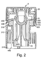
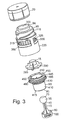
- FIG. 1(a) to 3 there is shown a closure assembly (or tamper-evident device), generally designated 5, according to a first embodiment of the present invention.
- the closure assembly 5 is adapted to be applied to a mouth and neck portion of a container for liquid (partly shown in outline in Figure 2).
- the closure assembly 5 comprises: a first member or tamper indication means 10; a baffle 15; and a container closure member 20, wherein prior to initial opening the first tamper indication means 10 is retained in association with the baffle 15 by first retaining means (first joint) 25, and the baffle 15 is retained in association with the container closure member 20 by second retaining means (second joint or clip) 30 ( Figure 1(a)), and wherein further initial opening of the closure assembly 5 causes in sequence release of the first retaining means 25 ( Figure 1(b)) and then the second retaining means 30 ( Figure 1(c)).
- a release force of the first retaining means 25 is less than a release force of the second retaining means 20.
- the first tamper indication means 10 may therefore be referred to as a drop-down flag.
- the closure assembly 5 also includes non-refilling means, such as valve means, as will hereinafter be described in greater detail.
- the first retaining means 25 comprises a ball or ball like member 35 carried at a first end 40 of the first tamper indication means 10 and a corresponding socket 45 is provided on the baffle 15.
- the second retaining means 30 comprises a male portion 50 provided on the baffle 15 and a corresponding female portion 55 provided on an inner face 60 of the container closure member 20.
- the ball 35 and socket 45 are a releasable friction or interference push-fit with one another.
- An enlarged radial portion 65 of the male portion 50 in an initial position co-acts with a reduced radial portion 70 of the female portion 55 to retain the male and female portion 50,55 together in a releasable push-fit.
- the ball 35 acts as a valve member 75 after initial opening.
- the movement prevention means comprise a widened second end 80 of the first tamper indication means 10 and an abutting surface 85 of a valve seat body 90.
- the first end 40 of the first tamper indication means 10 is provided within the valve seat body 90 and a pouring outlet device or body 95.
- the ball 35 having dropped from socket 45 acts as the valve member 75.
- the second end 80 of the first tamper indication means 10 comprises a flag member 100 or the like.
- the flag 100 can be suitably coloured to attract the eye and/or may carry information, e.g. marketing or promotional information.
- the valve seat body 90 can be made from a material selected such that in an initial assembly operation the ball 35 can be pushed through an aperture 105 in the valve seat body 90. This feature is of particular advantage for ease of manufacture.
- the container closure assembly 20 is threadably connected to a/the pouring outlet device 95 by interengaging and co-acting threaded portions on each 110,115.
- the first tamper indication means 10 can be made from a plastics material, e.g. polycarbonate.
- a further valve member (not shown) can be provided within the socket 45 between the socket 45 and the ball 35.
- the pouring outlet device 75 includes a pouring lip 96.
- the closure assembly 5 comprises a sleeve 220 adapted to lie substantially concentrically with respect to mouth 210 and provided with means for fixing the sleeve 220 on the container 215.
- the closure assembly 5 further comprises a first outer sleeve 225 being a substantially tight interference fit with the sleeve 220 but rotatable with respect thereto upon application of sufficient rotational force.
- the closure assembly 5 also comprises a second outer sleeve 230 separate from the first outer sleeve 225 and associated with a container closure member or cap 20. Between the initially unopened first and second outer sleeves 225, 230 there is provided a circumferentially extending cut line 231 (see Figure 1(a)) formed as will hereinafter be described.
- the cut line 231 extends 360° around the closure assembly 5 and separates the first and second outer sleeve 225, 230.
- the cut line 231 may be unperceivable or at least almost unperceivable by the naked eye.
- spacing means comprise second tamper indication or tamper-evident means.
- the first outer sleeve 225 has open first and second ends 240, 245, and the second outer sleeve 230 has a first closed end 250 and a second open end 255.
- the cap 20 includes a circumferential groove 260, and further provides a circumferential lip portion 265 located below and adjacent to the circumferential groove 260.
- the initially adjacent portions comprise initially adjacent respective circumferential edges 270, 275 of the first and second outer sleeves 225, 230.
- the first and second circumferential edges 270, 275 are prior to initial opening located in the circumferential groove 260 and are substantially adjacent one another.
- the first circumferential edge 270 expands or rides over the circumferential lip portion 265 and then recoils or retracts to substantially its original circumferential position so as to become positioned radially behind the circumferential lip portion 265.
- the circumferential lip portion 265 contracts or rides under the first circumferential edge 270 and then recoils or expands to substantially its original circumferential position so as to become positioned radially ahead of the first circumferential edge 270.
- This action or these actions position the circumferential lip portion 265 longitudinally between the first and second circumferential edges 270, 275 in an obstructive manner such that when the container 215 is reclosed by re-applying the cap 20, the first and second outer sleeves 225, 230 are spaced apart by the circumferential lip portion 265 located therebetween.
- first circumferential edge 270 of the first outer sleeve 225 there can be provided a first circumferential beaded portion on the first outer sleeve 225 adjacent first circumferential edge 270, and in a same manner the second circumferential edge 275 of the second outer sleeve 230 may provide a second circumferential beaded portion on the second outer sleeve 230 adjacent second circumferential edge 275.
- the first and second sleeves 225, 230 are made from any suitable material, e.g. a metal, or metallic based material.
- the metal substantially comprises aluminium or an alloy thereof, e.g. rolled aluminium.
- Aluminium provides a good medium for application of printing dyes, inks, paints or the like such that messages, logos, images, names, and other information may be carried by the first and second outer sleeves 225, 230.
- the cap 20 includes internally threaded portion 110 which co-acts with external threaded portion 115 on sleeve 220 or pouring outlet device 95, and allows for a rotational movement (normally-anti-clockwise) of the cap 20 during a container opening operation, and a contra-rotational movement (normally clockwise) of the cap 20 during a container closing (reclosing) operation.
- the closure assembly 5 includes a non-refillable device 290 comprising valve member 75 and providing pouring outlet device 95 adapted to be secured to the mouth 10 of the container 215 for liquid.
- the cap 20 is adapted to close an outlet 300 of the pouring outlet device 95, the first outer sleeve 225 optionally being located to receive at least part of the pouring outlet device 95.
- the outlet 300 is substantially annular and the cap 235 carries on an inner facing end 305 an annular seal 310 removably receivable within the annular outlet 300.
- the annular outlet 300 defines a circumferential pouring lip 96.
- the second outer sleeve 230 is adapted to receive the cap 20.
- the cap 20 is generally received in a tight interference fit to the second outer sleeve 230, but may be rotatable with respect to the second outer sleeve 235 upon application of sufficient force.
- further reclosure movement e.g., clockwise turning of second outer sleeve 225
- cap 20 to remain stationery and outer sleeve 225 to rotate relative thereto.
- the second circumferential edge 275 maintains the second outer sleeve 230 in longitudinal relation with the cap 20.
- the pouring outlet device 95 is, in this embodiment, made in one piece with the sleeve 220, e.g. by injection moulding.
- the non-refillable device 290 further comprises valve seat body 90 which is at least partially receivable within at least part of the neck portion 211 of the container 215, the valve seat body 90 being at least partially surrounded by the sleeve 220.
- Moveable valve member 75 is provided within the valve seat body 90.
- a non-return valve is formed from the valve seat body 90 and valve member 75 which is closed in a normally upright position of the bottle 215, and which while allowing liquids to flow from the bottle 215 in a pouring operation, restricts in-flow of liquid into the bottle 215 by rudimentary unauthorised filling operations or even more sophisticated methods which may involve attempted insertion of objects, tubes or the like into the bottle mouth 210.
- first outer sleeve 225 in longitudinal relation to the sleeve 220, e.g. an end 226 of the first outer sleeve 225 formed (bent) over an end 220 of the sleeve 220.
- the first and second circumferential edges 270, 275 of the first and second outer sleeves 270, 275 are before an initial opening of the closure assembly 5 located within the circumferential groove 260 provided on the cap 20, and are substantially adjacent. This positioning ensures that when the container 215 is initially opened by relative twisting of the cap 20 and sleeve 220, the second circumferential edge 275 of the second outer sleeve 230 remains within the groove 260 provided on the cap 20, and the first circumferential edge 270 of the first outer sleeve 225 progressively resiliently can be caused to move circumferentially outward and out of the groove 260 provided on the cap 235 as the cap 235 is removed away from the pouring outlet device 295 and the first outer sleeve 225 portion.
- the circumferential lip portion 265 can progressively resiliently move circumferentially inward.
- the first circumferential edge 270 retracts to a substantially reduced circumference (e.g. its original circumference), such that the resulting circumference is less than that of a cap portion which is located below the groove 260, e.g. circumferential lip portion 265.
- a longitudinal gap or void therefore remains between the first and second outer sleeves 225, 230 thus exposing a circumferential part of the cap 20, which includes at least part of the circumferential lip portion 265 which was originally encased or enclosed within the first outer sleeve 225.
- a further void also exists between a lower edge of the cap 20 and an original cap seating surface 320 of the pouring outlet device 95.
- the exposed circumferential part of the cap 20 can be distinctly coloured and/or printed with information, promotional messages or the like.
- the fixing means comprise first means 325 for fixing the sleeve 220 on the container 215 so as to restrain rotational movement of the sleeve 220 with respect to the neck portion 211 of the container 215.
- the fixing means also comprise second means 330 for fixing the sleeve 220 on the container 215 so as to restrict longitudinal movement of the sleeve 220 with respect to the mouth 210 of the container 215.
- the second means 330 for fixing the sleeve 220 are in the form of at least one projecting means 330 projecting inwardly of said sleeve 220, said at least one projecting means 330 being moveable radially of the sleeve 230 in a stiffly resilient manner and being engagable with an outer lip portion 212 of said container 215.
- the first outer sleeve 225 fits with the sleeve 220 by means of an interference fit between an outer surface 340 of the sleeve 220 and an inner surface 345 of the first outer sleeve 225.
- the cap 20 has therein threaded portion 285, which engages with a corresponding threaded portion 115 on the pouring outlet device 95.
- first and second outer sleeves 225,230 are aesthetically pleasing, and as such, the first and second outer sleeves 225,230 comprise metal foil.
- the projecting means 330 are provided on an inner wall of the sleeve 220 to resiliently engage the neck portion 211 and outer lip portion 212 of the container 215.
- the sleeve 220 contains one or more circumferential apertures 315 around the sleeve 220, which are defined between axially extending portions of the sleeve 220.
- The/each projecting means 330 are provided adjacent to an edge of one of the apertures 315.
- each projecting means 330 is positioned on a lower circumferential edge 360 of one of the apertures 315.
- the baffle 15 is provided with a circumferentially extending brim 390 which is positioned on the lower outer edge 395 of said baffle 15.
- the sleeve 220 is further conveniently provided with a plurality of ribs (or ridges) 405 formed on an inner surface 410 thereof, in this embodiment arranged circumferentially around the sleeve 220 and having their long axes arranged substantially axially to said sleeve 220.
- the valve seat body 90 comprises a tubular portion 410, a free end portion 415 of which provides a valve seat 420 adapted to be contacted in a sealing manner by valve member 7 captive in the tubular portion 410.
- the valve seat 420 comprises a circumferentially extending flange 421, which extends radially inwardly of the tubular portion 410.
- the valve seat 420 is positioned at one end of the tubular portion 410, and that end of the tubular portion 410 is closed except for an aperture which in this case is circular aperture 425.
- the tubular portion 410 is adapted to be received substantially within the mouth 210 portion of the container 215.
- the tubular portion 410 further comprises at least one engagement means 430 on an outer surface 235 thereof to engage an inner surface 440 of the container 215 in an interference fashion.
- the engagement means 430 comprise radially extending circumferential ribs.
- a substantially concentric further tubular portion 445 of greater diameter than the tubular portion 410 At or near to an end of the tubular portion 410 distant from the valve seat 420 is provided a substantially concentric further tubular portion 445 of greater diameter than the tubular portion 410, and an inner surface 445 of the further tubular portion 445 is connected to an outer surface 455 of the tubular portion 410 by one or more further webs 460. Further, a first end 465 of the further tubular portion 445 is connected to an outer surface 455 of the tubular portion 410 by an annular flange 475.
- Such construction provides a circumferential trough 480 defined between the outer surface 470 of the tubular portion 410 and an inner surface 450 of the further tubular body 475 with the flange 75 forming a trough floor.
- the trough 480 is divided into smaller arc-shaped troughs 485 by the webs 460.
- Such a trough 480 and/or troughs 485 help prevent
- a second end 490 of the further tubular portion 445 is arranged substantially flush with an end 495 of the tubular portion 410 distant from the valve seat 420.
- tubular portion 410 forms an inner sleeve of the assembled closure assembly 5.
- a radially extending circumferential rim 510 is located on an outer edge 515 of an end of the further tubular body 445, which, in an assembled closure assembly 5 is seated against a lower surface of a radially inwardly extending circumferential rim 425 provided on an inner surface of the sleeve 220.
- the container 215 is preferably a container for liquid.
- the container 215 is most likely a bottle, e.g. a glass bottle, suitable for containment of liquid, such as alcoholic drinks or beverages, e.g. spirits such as vodka, whisky, brandy, gin or the like.
- the bottle 215 is made from glass or alternatively a plastics material, the first and second outer sleeves 225, 230 from aluminium, the cap 20 from low density polyethylene, the sleeve 220 and pouring outlet device 95 from a stiffly resilient plastics material such as polypropylene or polystyrene and which in this embodiment is a polystyrene obtainable under the trade name, STYROLUX, the first tamper indication means 10 from polycarbonate, and the valve seat body 315 from low density polyethylene.
- a stiffly resilient plastics material such as polypropylene or polystyrene and which in this embodiment is a polystyrene obtainable under the trade name, STYROLUX
- the first tamper indication means 10 from polycarbonate
- the valve seat body 315 from low density polyethylene.
- a method of manufacturing the closure assembly 5 according to the present invention comprises the steps of:
- the ball 35 can be inserted into the valve seat body 90 by pushing the ball 35 through aperture 425.
- Step (d) is carried out using a first cutting tool such as a blade of a machine tool (not shown).
- Step (d) comprises: forming a cut around a portion of the outer sleeve member 224 so as to form the adjacent first and second circumferential edges 270 on the first and second outer sleeves 225,230. In this way the blade forms cut line 231 hereinbefore mentioned.
- first and second circumferential edges are formed in circumferential groove 260 carried on the container closure member 20. Also as can be seen, the first and second circumferential edges 275 are of reduced diameter compared to at least adjacent portions of the first or second outer sleeves 225,230 respectively.
- step (c) also comprises the step of: (e) forming end 226 of the first outer sleeve 225 over end 320 of the sleeve 220 so as to retain the first outer sleeve 225 and the sleeve 220 in longitudinal relation.
- Step (e) is carried out using a second cutting tool such as a further blade (not shown) of the machine tool. Steps (d) and (e) are beneficially undertaken substantially simultaneously, e.g. for reasons of speed of manufacture.
- the closure assembly 5 formed by this method comprises a unitary assembly for snap-on application to a mouth and neck portion 210, 211 of a container 215.
- a method of bottling according to the present invention comprises:
- FIG. 4(a) to (e) there are shown a sequence of cross-sectional side views of a closure assembly (tamper-evident device), generally designated 5a, according to a second embodiment of the present invention.
- the second embodiment is in many respects similar to the first embodiment hereinbefore described, like parts being designated with like numerals but suffixed "a".
- the second retaining means 30a comprises a female portion 50a, provided on the baffle 15a, and a corresponding male portion 55a provided on an inner face 60a of a retaining member or sealing wad 61a.
- the female portion 50a and male portion 55a are initially held together by an interference fit, which releases upon initial opening.
- the retaining member 61a is fixedly secured to the closure member 20a by lock means 62a, i.e. coacting ribs and grooves on the retaining member 61a and the closure member 20a.
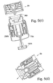
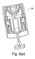
- FIG. 5b a sequence of cross-sectional side views of a closure assembly (tamper-evident device), generally designated 5b, according to a third embodiment of the present invention.
- the third embodiment is in many respects similar to the first and second embodiments hereinbefore described, like parts being designated with the numerals, but suffixed "b".
- the first retaining means 25b prior to initial opening retains the first member 10b in association with the container closure member 20b.
- the first retaining means 25b comprises female portion 50b provided on the ball 35b, and a corresponding male portion 55a provided on an inner face 60b of retaining member or sealing wad 61b.
- the female portion 50b and male portion 55b are initially held together by an interference fit which releases upon initial opening.
- the third embodiment provides a number of advantages over the other disclosed embodiments, e.g. a requirement for only one retaining means.
- the interference fit between the female portion 50b and the male portion 55b may be modified by provision of a positive clip therebetween, e.g. coacting groove and ribs, ball and socket, or the like.
- first retaining means are weaker than the second retaining means, but that both first and second retaining means are strong enough for transit purposes.
- the present invention provides a particularly desirable and elegant one-piece snap-on fitment having functional advantages over the prior art as well as enhanced aesthetic appeal.
- the second outer sleeve and/or the first outer sleeve may include knurred or castellated surfaces to assist in gripping in opening and reopening and/or closing and reclosing of the closure assembly.
- first and second circumferential edges of the first and second outer sleeves are substantially adjacent one another and may indeed even abut. However, they are preferably not connected together, e.g. by any frangible or weakened break-line, frangible or weakened links or frangible and/or removable tear ring, but rather are distinct and separate one from the other.
Landscapes
- Engineering & Computer Science (AREA)
- Mechanical Engineering (AREA)
- Closures For Containers (AREA)
- Devices For Use In Laboratory Experiments (AREA)
- Seal Device For Vehicle (AREA)
- Thermally Insulated Containers For Foods (AREA)
Abstract
Description
- The present invention relates to a closure assembly adapted to be applied to a mouth of a container (e.g. for liquid), such as a neck of a bottle. The invention particularly, thought not exclusively, relates to a tamper-evident snap-on fitment or tamper-evident non-refillable snap-on fitment. A closure assembly according to the preamble of claim 1 is known by, e.g.
WO 02/096771 - For various reasons, it may be desirable to ensure that a used container, such as a bottle intended to contain a liquid such as a valuable liquid, (e.g. alcoholic beverages such as spirits), is not re-filled with a replacement quantity of another liquid, the characteristics and quality of which may differ from the original contents. Attempts to provide closures which make such re-filling difficult are not always proof against determined re-filling efforts.
- Also, while it is considered advantageous to provide a tamper-indicating means which provides evidence that the bottle and its original contents are intact, if the bottle is resealable with a substitute cap or closure, there may be little to indicate to a purchaser that the bottle has been tampered with and/or refilled and that the contents may be inferior to the original contents.
- It has, therefore, been found desirable to provide a closure which cannot be removed without an extreme level of effort, or breakage being caused to the bottle. Such an arrangement is shown, for example, in
GB Patent No. 2 274 837 - Whilst it is very important that an original closure cannot be removed without visible damage or breakage being caused either to the closure and/or to the bottle, it has been found that a closure that cannot readily be removed will become the target of attempts to re-fill the container by overcoming the feature provided in the closure intended to hinder or prevent such refilling. Therefore, in addition to providing devices to prevent re-filling of bottles, there is a need to provide such devices with further tamper-indicating or "tamper-evident" features which, while not acting in any preventive role, give a clear irremovable and/or irreversible indication that a bottle has been opened since being originally filled with the genuine contents. Such clear indicators have been somewhat lacking in previous closure designs.
- Furthermore, there is a need for simple designs of closure assemblies allowing easy and reliable manufacture, assembly and fitting to bottle necks. Such simplicity has been somewhat lacking in previous closure designs.
- Accordingly, it is an object of the present invention to obviate or at least mitigate at least one of the aforementioned problems/disadvantages in the prior art.
- It is also an object of the present invention to invention to provide an improved closure assembly which does not have any parts which are removed upon initial opening and which are liable to be reattached by counterfeiters or the like in a way suggesting that the closure assembly had not previously been opened.
- It is a further object of the present invention to provide a closure assembly integrating the functions of tamper indicating means and of non-refillable valve means.
-
EP 0 985 607 A shows a tamper-evident closure device wherein after the initial opening of the container, as a result of the unscrewing of the cap, an extension is disposed in a position in which it is visible from outside the container providing evidence of opening, but the other end of the extension acting as tamper indication member does not act as a valve member. - According to the present invention, there is provided a closure assembly (or tamper-evident device) adapted to be applied to a mouth and neck portion of a container for liquid, according to claim 1.
- The Applicant has named the device of the present invention the "ALUSNAP" (Trade Mark) closure assembly, tamper-evident device, snap-on fitment or non-refillable device.
- In this way a clear indication is given to a person that the closure assembly has been opened and reclosed. The first tamper indication means therefore provides a first visual tamper-evidence means.
- Release of the first retaining means allows movement of the first tamper indication means from an initial position to a further position which indicates an initial opening of the closure assembly.
- The closure assembly may also include non-refilling means such as a valve means.
- Preferably the first retaining means comprises a ball carried at a first end of the first tamper indication means and a corresponding socket provided on the baffle.
- Preferably the second retaining means comprises a male portion provided on the baffle and a corresponding female portion provided on an inner face of the container closure member.
- The ball and socket may be a releasable friction or interference push-fit with one another. An enlarged radial portion of the male portion may in an initial position co-act with a reduced radial portion of the female portion to retain the male and female portions together in a releasable push-fit.
- The ball may act as a valve member after initial opening.
- Preferably in an initial unopened position there are provided means for preventing movement of the first tamper indication means in a direction towards the container closure member.
- Preferably the movement prevention means comprise a widened second end of the first temper indication means and an abutting surface of a valve seat body.
- Preferably the first end of the first tamper indication means is provided within the valve seat body and a pouring outlet device or body.
- Preferably in a position after initial opening the ball may act as a valve member.
- Preferably the second end of the first tamper indication means comprises a flag member or the like.
- The flag may be suitably coloured to attract the eye and/or may carry information, e.g. marketing or promotional information.
- The valve seat body may be made from a material selected such that in an initial assembly operation the ball may be pushed through an aperture in the valve seat body. This feature is of particular advantage for ease of manufacture.
- Preferably the container closure assembly is threadably connected to a/the pouring outlet device by interengaging threaded portions on each.
- The first tamper indication means may be made from a plastics material, e.g. polycarbonate.
- In a modification prior to initial opening, a further valve member may be provided within the socket between the socket and the ball.
- Preferably the pouring outlet device includes a pouring lip.
- The closure assembly may comprise a snap-on fitment.
- In one embodiment the closure assembly may comprise a sleeve adapted to lie substantially concentrically with respect to the mouth and provided with means for fixing the sleeve on the container, the closure assembly preferably further comprising a first outer sleeve being a substantially tight fit with the sleeve but rotatable with respect thereto, and a second outer sleeve separate from the first outer sleeve and associated with the container closure member, and wherein there are provided means for spacing apart initially adjacent portions of the first and second outer sleeves upon reclosure of the assembly after an initial opening of the container.
- The sleeve and container closure member may be made from suitable plastics materials.
- The spacing means may provide a second visual tamper indication or tamper-evidence means.
- Preferably the first outer sleeve has open first and second ends and the second outer sleeve has a first closed end and second open end.
- Preferably the container closure member includes a circumferential groove, which may further provide a circumferential lip portion located below and adjacent to the circumferential groove.
- The initially adjacent portions may comprise adjacent respective circumferential edges of the first and second outer sleeves.
- The first and second circumferential edges may prior to initial opening be located in the circumferential groove and may be adjacent one another.
- Preferably, during an initial container opening operation, the first circumferential edge expands or rides over the circumferential lip portion and then recoils or retracts, preferably to substantially its original circumferential position so as to become positioned circumferentially behind the circumferential lip portion. Alternatively or additionally during an initial container opening operation, the circumferential lip portion contracts or rides under the first circumferential edge and then recoils or expands preferably to substantially its original circumferential position so as to become positioned circumferentially ahead of the first circumferential edge. This action positions the circumferential lip longitudinally between the first and second circumferential edges in an obstructive manner such that when the container is reclosed by re-applying the closure member, the first and second outer sleeves are spaced apart at least by the circumferential lip portion located therebetween.
- The second tamper-evidence means provide that after reclosure the first and second circumferential edges are no longer adjacent but spaced, thus revealing a void or gap between the first and second circumferential edges. This visual indicator evidences that the closure assembly (and container) has been opened and reclosed.
- The first circumferential edge of the first outer sleeve may provide a circumferential first beaded portion on the first outer sleeve, and in a same manner the second circumferential edge of the second outer sleeve may provide a circumferential second beaded portion on the second outer sleeve.
- The first and second sleeves may comprise any suitable material, and preferably the material comprises a metal, or metallic based material.
- Preferably the metal or metallic based material substantially comprises aluminium or an alloy thereof, and particularly rolled aluminium.
- Advantageously, aluminium provides a good medium for application of printing dyes, inks, paints or the like such that messages, logos, images, names, and/or other information may be carried by the first and second outer sleeves. A message may, for example, comprise arrows indicating a direction of rotation for opening of the closure assembly.
- The container closure member may be a cap which desirably includes a threaded portion which allows a rotational movement (normally anti-clockwise) of the cap during a container opening operation.
- The closure assembly may include a non-refillable device provided within the pouring outlet device adapted to be secured to the mouth of a container for liquid. The container closure member may be a cap adapted to close an outlet of the pouring outlet device, and the first outer sleeve may be adapted to receive at least part of the pouring outlet device. The outlet may be substantially annular and the cap may carry on an inner facing end an annular seal removably receivable within the annular outlet.
- Preferably the second outer sleeve member is adapted to receive at least part of the cap.
- The cap may be generally received in a tight interference fit to the second outer sleeve, but may be optionally rotatable with respect to the second outer sleeve upon application of sufficient force.
- Desirably the pouring outlet device is made in one piece with the sleeve, e.g. by injection moulding.
- Preferably the non-refillable device further comprises a valve seat body which is at least partially receivable within at least part of the neck portion of the container, and wherein the valve seat body is at least partially surrounded by the sleeve.
- Preferably at least one moveable valve member is provided within the valve seat body.
- Preferably there are provided means for retaining the first outer sleeve in longitudinal relation to the sleeve, e.g. an end of the first outer sleeve at least partially formed over an end of the sleeve.
- Preferably the first and second circumferential edges of the first and second sleeves are before an initial opening of the closure assembly located within the circumferential groove provided on the cap, and are substantially adjacent. This positioning ensures that when the container is initially opened by relative twisting of the cap and sleeve, the second circumferential edge of the second outer sleeve remains within the groove provided on the cap, and the first circumferential edge of the first outer sleeve progressively resiliently may be caused to move circumferentially outward and out of the groove provided on the cap as the cap is removed away from the pouring outlet device and the first portion. Alternatively or additionally the circumferential lip portion may progressively be caused to move circumferentially inward. On removing the contact between the cap and the first circumferential edge of the first outer sleeve, the first circumferential edge retracts to a substantially reduced circumference, (e.g. its original circumference), such that the resulting circumference is less than that of a cap portion which is located below the groove. This cap portion is preferably provided as the circumferential lip on the cap.
- When the cap is re-applied to the pouring outlet device, a stop position is reached when the circumferential lip portion of the cap rests, sits or abuts upon the first circumferential edge of the first outer sleeve, thus preventing the cap being returned to its original unopened starting position. A longitudinal gap or void therefore remains between the first and second outer sleeves thus exposing a circumferential part of the cap, which includes at least part of the circumferential lip which was originally encased or enclosed within the first circumferential edge and an original cap seating surface of the pouring device.
- Advantageously the exposed circumferential part of the cap may be distinctly coloured and/or printed with information, promotional messages or the like.
- The fixing means may comprise first means for fixing the sleeve on the container so as to restrain rotational movement of the sleeve with respect to the neck portion of the container.
- The fixing means may also comprise second means for fixing the sleeve on the container so as to restrict longitudinal movement of the sleeve with respect to the mouth of the container.
- Preferably the second means for fixing the sleeve are in the form of at least one projecting means projecting inwardly of said sleeve, said at least one projecting means being moveable radially of the sleeve in a stiffly resilient manner and being engagable with an outer lip portion of said container.
- Preferably the first outer sleeve fits with the sleeve by means of an interference fit between an outer surface of the sleeve and an inner surface of the first outer sleeve.
- Preferably the cap has thereon a threaded portion, which engages with a corresponding threaded portion on the pouring outlet device.
- It is desired that the first and second outer sleeves are aesthetically pleasing, and as such, it is preferred that the first and second outer sleeves comprise metal foil.
- It is preferred that there are provided means for assembling at least the sleeve and valve seat body together and preferably all parts of the closure assembly together prior to application to the container. In such latter case, the closure assembly may be referred to as a "one piece fitment".
- Preferably the projecting means are provided on an inner wall of the sleeve to resiliently engage the neck portion of the container.
- Preferably the sleeve contains one or more circumferential apertures around the sleeve, which are defined between axially extending portions of the sleeve. The/each projecting means may be provided adjacent to an edge of one of the apertures. It is preferred that each projecting means is positioned on a lower circumferential edge of one of the apertures.
- Typically the pouring outlet device comprises a circumferentially extending pouring lip.
- Conveniently said baffle is provided with a circumferentially extending brim which is positioned on the lower outer edge of said baffle. The brim assists in deterring illicit refilling activities.
- The sleeve is further conveniently provided with a plurality of ribs or ridges formed on an inner surface thereof, preferably arranged circumferentially around the sleeve and having their long axes arranged substantially axially to said sleeve.
- These ribs or ridges, in use, may co-act with raised pips, ridges or the line, on an outer surface of the container (e.g. a "glass finish" of the bottle) to seek to prevent undesired rotational movement of the sleeve.
- The valve seat body may comprise a tubular portion, a free end portion of which provides a valve seat adapted to be contacted in a sealing manner by a valve member captive in said tubular portion.
- The valve seat is preferably a circumferentially extending flange, which extends radially inwardly of the tubular portion. In one embodiment such a valve seat is positioned at one end of the tubular portion, and that end of the tubular portion is closed except for a circular aperture.
- It will be understood that the tubular portion is adapted to be received substantially within the mouth portion of the container.
- The tubular portion may further comprise at least one engagement means on an outer surface thereof to engage an inner surface of the container in an interference fashion. The engagement means are preferably radially extending circumferential ribs.
- At or near to an end of the tubular portion distant from the valve seat is provided a substantially concentric further tubular portion of greater diameter than the tubular portion, and an inner surface of the further tubular portion is connected to an outer surface of the tubular portion by one or more webs.
- It is preferred that a first end of the further tubular portion is connected to an outer surface of the tubular portion by an annular flange.
- Thus, in one embodiment of the present invention, such construction provides a circumferential trough defined between the outer surface of the tubular portion and the inner surface of the further tubular portion with the flange forming a trough floor. The trough is divided into smaller arc-shaped troughs by the webs.
- Such a trough helps prevent insertion of objects into the container through the closure assembly.
- Preferably a second end of the further tubular portion is arranged substantially flush with an end of the tubular portion distant from the valve seat.
- In use the tubular portion forms an inner sleeve of the assembled closure assembly.
- Advantageously, an outer surface of the further tubular portion interference interacts with an inner surface of the sleeve and/or pouring outlet device.
- Conveniently, a radially extending circumferential rim is located on an outer edge of an end of the further tubular portion, which, in an assembled closure assembly is seated against a lower surface of a radially extending circumferential rim provided on an inner surface of the sleeve.
- According to a second aspect of the present invention there is provided a closure assembly (or tamper-evident device) adapted to be applied to a mouth and neck portion of a container for liquid, the assembly comprising:
- a first tamper indication means, and
- a container closure member, and wherein prior to initial opening the first tamper indication means and the closure member are retained in association with one another by push-fit or interference fit retaining means,
- and wherein further
- initial opening causes release of the push-fit or interference fit retaining means.
- In other words, initial opening causes release of the first tamper indication means from the container closure member.
- The push-fit or interference fit retaining means may comprise first retaining means for retaining the first tamper indication means in association with a baffle and second retaining means for retaining the baffle in association with the container closure member.
- Preferably release of the retaining means may cause the first tamper indication means to move from a first position to a second position. Such movement is indicative of initial opening. Preferably in said second position, the first tamper indication means is visible within the container, and preferably hangs in the container.
- According to a third aspect of the present invention there is provided a closure assembly (or tamper-evident device) according to claim 1 wherein prior to initial opening the first member and the container closure member are retained in association with one another by retaining means, and wherein further
initial opening of the closure assembly causes release of the retaining means which causes the first member thereafter to act as a valve member. - The first member may comprise a first tamper indication member, e.g. a first visual tamper-evidence means. The retaining means may comprise a releasable push/ clip/interference fit retaining means.
- In one implementation the retaining means may comprise first retaining means for retaining the first member in association with a baffle and second retaining means for retaining the baffle in association with the container closure member.
- In an alternative implementation the retaining means may comprise first retaining means for retaining the first member in association with the container closure member.
- In either case the container closure member may comprise a cap and a retaining member.
- Preferably the retaining member is securely fixed to the cap by lock means, e.g, co-acting ribs and grooves on the retaining member and the cap.
- Prior to initial opening the first member may be retained in association with the baffle by the first retaining means, and the baffle may be retained in association with the container closure member by the second retaining means, and wherein further
initial opening of the closure assembly may cause in sequence release of the first retaining means and release of the second retaining means. - Release of the retaining means may cause or allow movement of the first member from an initial position to a further position which indicates an initial opening of the closure assembly.
- Said movement may comprise the first member dropping from said initial position to said further position.
- According to a fourth embodiment of the present invention there is provided a container including a closure assembly according to the present invention.
- The container is preferably a container for liquid.
- The container may be a bottle, e.g. a glass bottle, and may be adapted for containment of liquid, such as alcoholic drinks or beverages, e.g. spirits such as vodka, whisky, brandy, gin or the like.
- According to a fifth embodiment of the present invention there is provided a combination of a container and a closure assembly according to the present invention.
- According to a sixth embodiment of the present invention there is provided an alcoholic drinks product comprising an alcoholic substance packaged in the combination according to the fourth embodiment of the present invention.
- According to a seventh embodiment of the present invention there is provided a method of manufacturing a closure. assembly according to the present invention comprising the steps of:
- (a) providing an outer sleeve member;
- (b) providing a pouring outlet device and a sleeve adapted to be secured to a mouth and neck portion of a container for liquid and a container closure member releasably securable to the pouring outlet device and/or sleeve;
- (c) disposing the pouring outlet device, sleeve and container closure member at least partly within the outer sleeve member;
- (d) forming the outer sleeve member into a first outer sleeve and a separate second outer sleeve.
- This method is particularly advantageous in mass production.
- Preferably step (d) is carried out using a first cutting tool such as a blade of a machine tool.
- Preferably step (d) comprises:
- forming a cut around a portion of the outer sleeve member so as to form adjacent first and second circumferential edges on the first and second outer sleeves.
- Advantageously, the first and second edges are formed in a groove carried on the container closure member.
- Advantageously the first and second circumferential edges are of reduced diameter compared to at least adjacent portions of the first or second outer sleeve, respectively.
- Preferably after step (c) the method also comprises the step of:
- (e) forming an end of the first outer sleeve over an end of the sleeve so as to retain the first outer sleeve and the sleeve in longitudinal relation.
- Preferably step (e) is carried out using a second cutting tool such as a further blade of a machine tool.
- Steps (d) and (e) may be undertaken substantially simultaneously.
- The closure assembly so formed may comprise a unitary assembly for snap-on application to a mouth and neck portion of a container.
- According to an eighth embodiment of the present invention there is provided a method of bottling comprising:
- (a) providing a closure assembly according to the present invention;
- (b) providing a bottle;
- (c) filling the bottle with a liquid;
- (d) closing the bottle by applying the closure assembly to a mouth and neck of the bottle.
- According to a ninth embodiment of the present invention there is provided a method of manufacturing a closure assembly according to the present invention, wherein the method comprises the steps of:
- (a) providing a valve seat body and a valve member; and
- (b) assembling the valve seat body and valve member together by pushing the valve member through an aperture in the valve seat body, a width of the valve member being greater than a width of the aperture in the valve seat body.
- According to a tenth embodiment of the present invention there is provided a closure assembly (or tamper-evident device) according to the present invention wherein prior to initial opening the first member and the container closure member are retained in association with one another by retaining means, and wherein further
initial opening of the closure assembly causes release of the retaining means which causes the first member thereafter to act as a first tamper evidence or indication means or member. - Embodiments of the present invention will now be described by way of example only, and with reference to the accompanying drawings, which are:
- Figure 1 (a)
- a cross-sectional side view of a closure assembly according to a first embodiment of the present invention prior to an initial opening operation;
- Figure 1(b)
- a cross-sectional side view of the closure assembly of Figure 1(a) during an initial opening operation;
- Figure 1(c)
- a cross-sectional side view of the closure assembly of Figure 1(a) after an initial (or subsequent) opening operation;
- Figure 1(d)
- a cross-sectional side view of the closure assembly of Figure 1(a) after a reclosure operation;
- Figure 2
- a further cross-sectional side view of the closure assembly of Figure 1(a) prior to an initial opening operation;
- Figure 3
- an exploded perspective view of component parts of the closure assembly of Figure 1(a).
- Figures 4(a) to (e)
- a sequence of cross-sectional side views of a closure assembly according to a second embodiment of the present invention:
- (a) unopened;
- (b) during first opening;
- (c) opened;
- (d) during pouring; and
- (e) reclosed; and
- Figures 5(a) to (e)
- a sequence of cross-sectional side views of a closure assembly according to a third embodiment of the present invention:
- (a) unopened;
- (b) during first opening;
- (c) opened;
- (d) during pouring; and
- (e) reclosed.
- Referring to Figures 1(a) to 3, there is shown a closure assembly (or tamper-evident device), generally designated 5, according to a first embodiment of the present invention. The
closure assembly 5 is adapted to be applied to a mouth and neck portion of a container for liquid (partly shown in outline in Figure 2). Theclosure assembly 5 comprises: a first member or tamper indication means 10; abaffle 15; and acontainer closure member 20, wherein prior to initial opening the first tamper indication means 10 is retained in association with thebaffle 15 by first retaining means (first joint) 25, and thebaffle 15 is retained in association with thecontainer closure member 20 by second retaining means (second joint or clip) 30 (Figure 1(a)), and wherein further initial opening of theclosure assembly 5 causes in sequence release of the first retaining means 25 (Figure 1(b)) and then the second retaining means 30 (Figure 1(c)). - In other words, a release force of the first retaining means 25 is less than a release force of the second retaining means 20.
- Release of the first retaining means 25 allows movement of the first tamper indication means 10 from an initial position to a further position which indicates an initial opening of the
closure assembly 5. The first tamper indication means 10 may therefore be referred to as a drop-down flag. - The
closure assembly 5 also includes non-refilling means, such as valve means, as will hereinafter be described in greater detail. - The first retaining means 25 comprises a ball or ball like
member 35 carried at afirst end 40 of the first tamper indication means 10 and a correspondingsocket 45 is provided on thebaffle 15. - The second retaining means 30 comprises a
male portion 50 provided on thebaffle 15 and a correspondingfemale portion 55 provided on aninner face 60 of thecontainer closure member 20. - The
ball 35 andsocket 45 are a releasable friction or interference push-fit with one another. An enlargedradial portion 65 of themale portion 50 in an initial position co-acts with a reducedradial portion 70 of thefemale portion 55 to retain the male andfemale portion - The
ball 35 acts as avalve member 75 after initial opening. - In an initial unopened position there are provided means for preventing movement of the first tamper indication means 10 in a direction towards the
container closure member 20. The movement prevention means comprise a widenedsecond end 80 of the first tamper indication means 10 and an abuttingsurface 85 of avalve seat body 90. Thefirst end 40 of the first tamper indication means 10 is provided within thevalve seat body 90 and a pouring outlet device orbody 95. - In a position after initial opening, the
ball 35 having dropped fromsocket 45, acts as thevalve member 75. - The
second end 80 of the first tamper indication means 10 comprises aflag member 100 or the like. Theflag 100 can be suitably coloured to attract the eye and/or may carry information, e.g. marketing or promotional information. - The
valve seat body 90 can be made from a material selected such that in an initial assembly operation theball 35 can be pushed through an aperture 105 in thevalve seat body 90. This feature is of particular advantage for ease of manufacture. - The
container closure assembly 20 is threadably connected to a/the pouringoutlet device 95 by interengaging and co-acting threaded portions on each 110,115. - The first tamper indication means 10 can be made from a plastics material, e.g. polycarbonate.
- In a modification prior to initial opening a further valve member (not shown) can be provided within the
socket 45 between thesocket 45 and theball 35. - As can be seen in Figure 3, the pouring
outlet device 75 includes a pouringlip 96. - The
closure assembly 5 comprises asleeve 220 adapted to lie substantially concentrically with respect tomouth 210 and provided with means for fixing thesleeve 220 on thecontainer 215. Theclosure assembly 5 further comprises a firstouter sleeve 225 being a substantially tight interference fit with thesleeve 220 but rotatable with respect thereto upon application of sufficient rotational force. Theclosure assembly 5 also comprises a secondouter sleeve 230 separate from the firstouter sleeve 225 and associated with a container closure member orcap 20. Between the initially unopened first and secondouter sleeves cut line 231 extends 360° around theclosure assembly 5 and separates the first and secondouter sleeve cut line 231 may be unperceivable or at least almost unperceivable by the naked eye. - There are also provided means for spacing apart initially adjacent portions of the first and second
outer sleeves closure assembly 5 after an initial opening of thecontainer 215, as will hereinafter be described in greater detail, which spacing means comprise second tamper indication or tamper-evident means. - The first
outer sleeve 225 has open first and second ends 240, 245, and the secondouter sleeve 230 has a firstclosed end 250 and a secondopen end 255. - The
cap 20 includes acircumferential groove 260, and further provides acircumferential lip portion 265 located below and adjacent to thecircumferential groove 260. - The initially adjacent portions comprise initially adjacent respective
circumferential edges outer sleeves circumferential edges circumferential groove 260 and are substantially adjacent one another. - During an initial container opening operation, the first
circumferential edge 270 expands or rides over thecircumferential lip portion 265 and then recoils or retracts to substantially its original circumferential position so as to become positioned radially behind thecircumferential lip portion 265. Alternatively or additionally during an initial container opening operation, thecircumferential lip portion 265 contracts or rides under the firstcircumferential edge 270 and then recoils or expands to substantially its original circumferential position so as to become positioned radially ahead of the firstcircumferential edge 270. This action or these actions position thecircumferential lip portion 265 longitudinally between the first and secondcircumferential edges container 215 is reclosed by re-applying thecap 20, the first and secondouter sleeves circumferential lip portion 265 located therebetween. - By this arrangement after reclosure the first and second
circumferential edges groove 260 andlip portion 265 between the first and secondcircumferential edges - In a modification at or near the first
circumferential edge 270 of the firstouter sleeve 225 there can be provided a first circumferential beaded portion on the firstouter sleeve 225 adjacent firstcircumferential edge 270, and in a same manner the secondcircumferential edge 275 of the secondouter sleeve 230 may provide a second circumferential beaded portion on the secondouter sleeve 230 adjacent secondcircumferential edge 275. - The first and
second sleeves outer sleeves - The
cap 20 includes internally threadedportion 110 which co-acts with external threadedportion 115 onsleeve 220 or pouringoutlet device 95, and allows for a rotational movement (normally-anti-clockwise) of thecap 20 during a container opening operation, and a contra-rotational movement (normally clockwise) of thecap 20 during a container closing (reclosing) operation. - The
closure assembly 5 includes anon-refillable device 290 comprisingvalve member 75 and providing pouringoutlet device 95 adapted to be secured to themouth 10 of thecontainer 215 for liquid. Thecap 20 is adapted to close anoutlet 300 of the pouringoutlet device 95, the firstouter sleeve 225 optionally being located to receive at least part of the pouringoutlet device 95. Theoutlet 300 is substantially annular and thecap 235 carries on an inner facing end 305 anannular seal 310 removably receivable within theannular outlet 300. Theannular outlet 300 defines a circumferential pouringlip 96. - The second
outer sleeve 230 is adapted to receive thecap 20. Thecap 20 is generally received in a tight interference fit to the secondouter sleeve 230, but may be rotatable with respect to the secondouter sleeve 235 upon application of sufficient force. For example, upon reclosure of theclosure assembly 5, whencircumferential lip portion 265 abuts firstcircumferential edge 270 further reclosure movement (e.g., clockwise turning of second outer sleeve 225) can causecap 20 to remain stationery andouter sleeve 225 to rotate relative thereto. Further, the secondcircumferential edge 275 maintains the secondouter sleeve 230 in longitudinal relation with thecap 20. - The pouring
outlet device 95 is, in this embodiment, made in one piece with thesleeve 220, e.g. by injection moulding. - The
non-refillable device 290 further comprisesvalve seat body 90 which is at least partially receivable within at least part of the neck portion 211 of thecontainer 215, thevalve seat body 90 being at least partially surrounded by thesleeve 220.Moveable valve member 75 is provided within thevalve seat body 90. - A non-return valve is formed from the
valve seat body 90 andvalve member 75 which is closed in a normally upright position of thebottle 215, and which while allowing liquids to flow from thebottle 215 in a pouring operation, restricts in-flow of liquid into thebottle 215 by rudimentary unauthorised filling operations or even more sophisticated methods which may involve attempted insertion of objects, tubes or the like into thebottle mouth 210. - There are provided means for retaining the first
outer sleeve 225 in longitudinal relation to thesleeve 220, e.g. anend 226 of the firstouter sleeve 225 formed (bent) over anend 220 of thesleeve 220. - The first and second
circumferential edges outer sleeves closure assembly 5 located within thecircumferential groove 260 provided on thecap 20, and are substantially adjacent. This positioning ensures that when thecontainer 215 is initially opened by relative twisting of thecap 20 andsleeve 220, the secondcircumferential edge 275 of the secondouter sleeve 230 remains within thegroove 260 provided on thecap 20, and the firstcircumferential edge 270 of the firstouter sleeve 225 progressively resiliently can be caused to move circumferentially outward and out of thegroove 260 provided on thecap 235 as thecap 235 is removed away from the pouring outlet device 295 and the firstouter sleeve 225 portion. Alternatively or additionally as mentioned above, thecircumferential lip portion 265 can progressively resiliently move circumferentially inward. On removing the contact between thecap 20 and the firstcircumferential edge 270 of the firstouter sleeve 225, the firstcircumferential edge 270 retracts to a substantially reduced circumference (e.g. its original circumference), such that the resulting circumference is less than that of a cap portion which is located below thegroove 260, e.g.circumferential lip portion 265. - When the
cap 20 is re-applied to the pouringoutlet device 95, a stop position is reached when thecircumferential lip portion 265 of thecap 20 rests, sits or abuts upon the firstcircumferential edge 270 of the firstouter sleeve 225, thus preventing thecap 235 being returned to its original starting (unopened) position. A longitudinal gap or void therefore remains between the first and secondouter sleeves cap 20, which includes at least part of thecircumferential lip portion 265 which was originally encased or enclosed within the firstouter sleeve 225. A further void (not shown) also exists between a lower edge of thecap 20 and an original cap seating surface 320 of the pouringoutlet device 95. - Advantageously the exposed circumferential part of the
cap 20 can be distinctly coloured and/or printed with information, promotional messages or the like. - The fixing means comprise first means 325 for fixing the
sleeve 220 on thecontainer 215 so as to restrain rotational movement of thesleeve 220 with respect to the neck portion 211 of thecontainer 215. - The fixing means also comprise second means 330 for fixing the
sleeve 220 on thecontainer 215 so as to restrict longitudinal movement of thesleeve 220 with respect to themouth 210 of thecontainer 215. The second means 330 for fixing thesleeve 220 are in the form of at least one projecting means 330 projecting inwardly of saidsleeve 220, said at least one projecting means 330 being moveable radially of thesleeve 230 in a stiffly resilient manner and being engagable with anouter lip portion 212 of saidcontainer 215. - The first
outer sleeve 225 fits with thesleeve 220 by means of an interference fit between anouter surface 340 of thesleeve 220 and aninner surface 345 of the firstouter sleeve 225. Thecap 20 has therein threaded portion 285, which engages with a corresponding threadedportion 115 on the pouringoutlet device 95. - It is desired that the first and second outer sleeves 225,230 are aesthetically pleasing, and as such, the first and second outer sleeves 225,230 comprise metal foil.
- There are provided
means 346 for assembling thesleeve 220 andvalve seat body 90 together prior to application to thecontainer 215, such as co-acting ribs and grooves carried by each. - The projecting means 330 are provided on an inner wall of the
sleeve 220 to resiliently engage the neck portion 211 andouter lip portion 212 of thecontainer 215. - The
sleeve 220 contains one or morecircumferential apertures 315 around thesleeve 220, which are defined between axially extending portions of thesleeve 220. The/each projecting means 330 are provided adjacent to an edge of one of theapertures 315. - As can be seen in this
closure assembly 5, each projecting means 330 is positioned on a lowercircumferential edge 360 of one of theapertures 315. - The
baffle 15 is provided with acircumferentially extending brim 390 which is positioned on the lowerouter edge 395 of saidbaffle 15. - The
sleeve 220 is further conveniently provided with a plurality of ribs (or ridges) 405 formed on aninner surface 410 thereof, in this embodiment arranged circumferentially around thesleeve 220 and having their long axes arranged substantially axially to saidsleeve 220. Theseribs 405, in use, form first means 325 for anti-rotation and co-act with raised pips, ridges or the like (not shown), on an outer surface of the container 215 (comprising a so-called "glass finish" of the bottle) to seek to prevent undesired rotational movement of thesleeve 220. - Some minor rotational play in either a clockwise or anticlockwise direction may occur until a stop position is found by a rib or
ribs 405 acting against a ridge or ridges. However, continued application of force will cause the firstouter sleeve 235 and/or the secondouter sleeve 230 to rotate relative to thesleeve 220 and/orcap 235, respectively. - The
valve seat body 90 comprises atubular portion 410, afree end portion 415 of which provides avalve seat 420 adapted to be contacted in a sealing manner by valve member 7 captive in thetubular portion 410. Thevalve seat 420 comprises acircumferentially extending flange 421, which extends radially inwardly of thetubular portion 410. In this embodiment thevalve seat 420 is positioned at one end of thetubular portion 410, and that end of thetubular portion 410 is closed except for an aperture which in this case iscircular aperture 425. - The
tubular portion 410 is adapted to be received substantially within themouth 210 portion of thecontainer 215. Thetubular portion 410 further comprises at least one engagement means 430 on anouter surface 235 thereof to engage aninner surface 440 of thecontainer 215 in an interference fashion. The engagement means 430 comprise radially extending circumferential ribs. - At or near to an end of the
tubular portion 410 distant from thevalve seat 420 is provided a substantially concentric furthertubular portion 445 of greater diameter than thetubular portion 410, and aninner surface 445 of the furthertubular portion 445 is connected to anouter surface 455 of thetubular portion 410 by one or morefurther webs 460. Further, afirst end 465 of the furthertubular portion 445 is connected to anouter surface 455 of thetubular portion 410 by an annular flange 475. Such construction provides acircumferential trough 480 defined between the outer surface 470 of thetubular portion 410 and aninner surface 450 of the further tubular body 475 with theflange 75 forming a trough floor. Thetrough 480 is divided into smaller arc-shapedtroughs 485 by thewebs 460. Such atrough 480 and/ortroughs 485 help prevent insertion of objects into thecontainer 215 through theclosure assembly 5. - A
second end 490 of the furthertubular portion 445 is arranged substantially flush with anend 495 of thetubular portion 410 distant from thevalve seat 420. - In use, the
tubular portion 410 forms an inner sleeve of the assembledclosure assembly 5. - An
outer surface 500 of the furthertubular body 445 interference interacts with aninner surface 505 of thesleeve 420. Conveniently, a radially extendingcircumferential rim 510 is located on anouter edge 515 of an end of the furthertubular body 445, which, in an assembledclosure assembly 5 is seated against a lower surface of a radially inwardly extendingcircumferential rim 425 provided on an inner surface of thesleeve 220. - The
container 215 is preferably a container for liquid. Thecontainer 215 is most likely a bottle, e.g. a glass bottle, suitable for containment of liquid, such as alcoholic drinks or beverages, e.g. spirits such as vodka, whisky, brandy, gin or the like. - Typically, the
bottle 215 is made from glass or alternatively a plastics material, the first and secondouter sleeves cap 20 from low density polyethylene, thesleeve 220 and pouringoutlet device 95 from a stiffly resilient plastics material such as polypropylene or polystyrene and which in this embodiment is a polystyrene obtainable under the trade name, STYROLUX, the first tamper indication means 10 from polycarbonate, and thevalve seat body 315 from low density polyethylene. - A method of manufacturing the
closure assembly 5 according to the present invention comprises the steps of: - (a) providing an outer sleeve member 224;
- (b) providing pouring
outlet device 95 andsleeve 220 adapted to be secured to mouth and/or neck portion 210,211 ofcontainer 215 for liquid, andcontainer closure member 20 releasably securable to the pouringoutlet device 95 and/orsleeve 220; - (c) disposing the pouring
outlet device 95,sleeve 220 andcontainer closure member 20 at least partly within the outer sleeve member 224; - (d) forming the outer sleeve member 224 into first
outer sleeve 225 and separate secondouter sleeve 230. - As mentioned hereinbefore, the
ball 35 can be inserted into thevalve seat body 90 by pushing theball 35 throughaperture 425. - This method is particularly advantageous in mass production. Step (d) is carried out using a first cutting tool such as a blade of a machine tool (not shown).
- Step (d) comprises: forming a cut around a portion of the outer sleeve member 224 so as to form the adjacent first and second
circumferential edges 270 on the first and second outer sleeves 225,230. In this way the blade forms cutline 231 hereinbefore mentioned. - As can be seen from Figure 1(a), where provided, the first and second circumferential edges are formed in
circumferential groove 260 carried on thecontainer closure member 20. Also as can be seen, the first and secondcircumferential edges 275 are of reduced diameter compared to at least adjacent portions of the first or second outer sleeves 225,230 respectively. - After step (c) the method also comprises the step of: (e) forming
end 226 of the firstouter sleeve 225 over end 320 of thesleeve 220 so as to retain the firstouter sleeve 225 and thesleeve 220 in longitudinal relation. Step (e) is carried out using a second cutting tool such as a further blade (not shown) of the machine tool. Steps (d) and (e) are beneficially undertaken substantially simultaneously, e.g. for reasons of speed of manufacture. - The
closure assembly 5 formed by this method comprises a unitary assembly for snap-on application to a mouth andneck portion 210, 211 of acontainer 215. - A method of bottling according to the present invention comprises:
- (a) providing
closure assembly 5; - (b) providing a
bottle 215; - (c) filling the
bottle 215 with a liquid; - (d) closing the
bottle 215 by applying theclosure assembly 5 to a mouth and neck portion 210,211 of thebottle 215. - Referring next to Figures 4(a) to (e), there are shown a sequence of cross-sectional side views of a closure assembly (tamper-evident device), generally designated 5a, according to a second embodiment of the present invention. The second embodiment is in many respects similar to the first embodiment hereinbefore described, like parts being designated with like numerals but suffixed "a".
- However, in the second embodiment the second retaining means 30a comprises a
female portion 50a, provided on thebaffle 15a, and a correspondingmale portion 55a provided on aninner face 60a of a retaining member or sealingwad 61a. As can be seen from Figure 4(a), thefemale portion 50a andmale portion 55a are initially held together by an interference fit, which releases upon initial opening. Further, the retainingmember 61a is fixedly secured to theclosure member 20a by lock means 62a, i.e. coacting ribs and grooves on the retainingmember 61a and theclosure member 20a. - Referring finally to Figures 5(a) to (e), there are shown a sequence of cross-sectional side views of a closure assembly (tamper-evident device), generally designated 5b, according to a third embodiment of the present invention. The third embodiment is in many respects similar to the first and second embodiments hereinbefore described, like parts being designated with the numerals, but suffixed "b".
- However, in the third embodiment there is no baffle or second retaining means. Rather, the first retaining means 25b prior to initial opening retains the
first member 10b in association with thecontainer closure member 20b. The first retaining means 25b comprisesfemale portion 50b provided on theball 35b, and a correspondingmale portion 55a provided on aninner face 60b of retaining member or sealingwad 61b. As can be seen from Figure 5(a), thefemale portion 50b andmale portion 55b are initially held together by an interference fit which releases upon initial opening. - The third embodiment provides a number of advantages over the other disclosed embodiments, e.g. a requirement for only one retaining means.
- In a modification to the second and third embodiments, the interference fit between the
female portion 50b and themale portion 55b may be modified by provision of a positive clip therebetween, e.g. coacting groove and ribs, ball and socket, or the like. - It will be understood that the embodiments of the present invention hereinbefore described are given by way of non-limiting example only, and that modifications may be made without departing from the scope of the present invention as set forth in the appended claims.
- It will particularly be appreciated that the first retaining means are weaker than the second retaining means, but that both first and second retaining means are strong enough for transit purposes.
- It will also be appreciated that the provision of the releasable push-fit first and optional second retaining means provide a particularly simple to manufacture, assemble, and use solution to the aforementioned problems in the art.
- It will be further appreciated that the present invention provides a particularly desirable and elegant one-piece snap-on fitment having functional advantages over the prior art as well as enhanced aesthetic appeal.
- In a modification, the second outer sleeve and/or the first outer sleeve may include knurred or castellated surfaces to assist in gripping in opening and reopening and/or closing and reclosing of the closure assembly.
- Finally, it will be appreciated that in at least one disclosed embodiment of the closure assembly of the present invention prior to an initial opening, the first and second circumferential edges of the first and second outer sleeves are substantially adjacent one another and may indeed even abut. However, they are preferably not connected together, e.g. by any frangible or weakened break-line, frangible or weakened links or frangible and/or removable tear ring, but rather are distinct and separate one from the other.
Claims (11)
- A closure assembly (5) adapted to be applied to a mouth (210) and neck portion of a container for liquid, comprising:- a sleeve (220) adapted to lie substantially concentrically with respect to the mouth (210),- means (325) for fixing the sleeve (220) on the container,- a pouring outlet device (95), with a liquid outlet, adapted to be secured to the mouth (210) of the container,- a container closure member (20) removably fitted on said pouring outlet device (95), adapted to open and close the liquid outlet of the pouring device (95);- a non refillable device (290) within said pouring outlet device (95),- said sleeve (220) being adapted to receive at least part of said non refillable device (290),- said non refillable device (290) comprising a tubular portion (410), a free end (415) of which provides a body (90) for a valve seat (420),- a tamper indication member (10) captive in said tubular portion (410),- said tamper indication member (10) comprising a first end (40) and a second end (80),characterized by the fact that it includes first retaining means (25) for retaining the first end (40) of said tamper indication member (10) in association with the container closure member (20) prior to initial opening of the closure assembly (5) and for releasing said first end (40) further initial opening of the closure assembly (5), whereby said tamper indication member (10) is caused to drop from an initial position to a further position which indicates the initial opening of the closure assembly (5), the first end (40) of the tamper indication member (10) is caused to act on said valve seat (420) in a sealing manner and said second end (80) is caused to act as a visual tamper-evidence indication means.
- A closure assembly as claimed in claim 1, wherein the closure member (20) comprises a cap which is threadably connected to the pouring outlet device (95) by interengaging threaded portions on each.
- A closure assembly as claimed in claims 1 and 2, wherein said first retaining means (25) for retaining the first end (40) of said tamper indication member (10) in association with the container closure member (20), comprises a releasable push/clip/interference fit retaining means.
- A closure assembly according to claims 1 to 3, wherein said first end (40) of the tamper indication member (10) acting on said valve seat (420) after initial opening of the closure, comprises a ball portion (35).
- A closure assembly according to claims 1 to 4 wherein said second end (80) of the tamper indication member (10) comprises a flag member.
- A closure assembly according to claim 5 wherein the flag is suitably coloured to attract the eye and/or carries information, such as marketing or promotional information.
- A closure assembly according to claim 1 to 6, wherein a baffle (15) is provided in association with the container closure member (20), second retaining means (30) being provided for retaining said baffle (15) in association with the container closure member (20) and said first retaining means (25) being provided for retaining the first end (40) of said tamper indication member (10) in association with the baffle (15).
- A closure assembly according to claim 7, wherein said first retaining means (25) comprises a ball (35) carried at the first end (40) of the tamper indication member (10) and a corresponding socket (45) provided on the baffle (15).
- A closure assembly according to claim 7, wherein said second retaining means (30) comprises a male/female portion provided on the baffle (15) and a corresponding female/male portion provided on an inner face of the container closure member (20).
- A closure assembly according to the preceding claims, wherein in an initial unopened position there are provided means for preventing movement of the tamper indication member (10) in a direction towards the container closure member (20).
- A closure assembly according to claim 10, wherein the movement prevention means comprise a widened second end (80) of the tamper indication member (10) and an abutting surface (85) of the valve seat body (80).
Applications Claiming Priority (3)
| Application Number | Priority Date | Filing Date | Title |
|---|---|---|---|
| GB0301818 | 2003-01-25 | ||
| GBGB0301818.1A GB0301818D0 (en) | 2003-01-25 | 2003-01-25 | Liquid container closure assembly |
| PCT/GB2004/000189 WO2004067387A2 (en) | 2003-01-25 | 2004-01-22 | Liquid container closure assembly |
Publications (2)
| Publication Number | Publication Date |
|---|---|
| EP1585684A2 EP1585684A2 (en) | 2005-10-19 |
| EP1585684B1 true EP1585684B1 (en) | 2007-08-22 |
Family
ID=9951863
Family Applications (1)
| Application Number | Title | Priority Date | Filing Date |
|---|---|---|---|
| EP04704267A Expired - Lifetime EP1585684B1 (en) | 2003-01-25 | 2004-01-22 | Liquid container closure assembly |
Country Status (12)
| Country | Link |
|---|---|
| EP (1) | EP1585684B1 (en) |
| KR (1) | KR101070559B1 (en) |
| CN (1) | CN100355632C (en) |
| AT (1) | ATE370894T1 (en) |
| BR (1) | BRPI0406972B1 (en) |
| DE (1) | DE602004008423T2 (en) |
| EA (1) | EA007834B1 (en) |
| ES (1) | ES2294459T3 (en) |
| GB (2) | GB0301818D0 (en) |
| MX (1) | MXPA05007720A (en) |
| UA (1) | UA80858C2 (en) |
| WO (1) | WO2004067387A2 (en) |
Families Citing this family (20)
| Publication number | Priority date | Publication date | Assignee | Title |
|---|---|---|---|---|
| UA5263U (en) * | 2004-08-09 | 2005-02-15 | Общєство С Огранічєнной Отвєтствєнностью Торговий Дом "Альтернатіва-Ана" | Bottle plug |
| ITMI20060247A1 (en) * | 2006-02-10 | 2007-08-11 | Nicola Fabiano | CLOSING DEVICE FOR BOTTLES AND OPARTYICULAR FOR BOTTLES OF ALCOHOLIC AND SUPERCHOLICS |
| ITMI20061920A1 (en) * | 2006-10-06 | 2008-04-07 | Nicola Fabiano | ANTI-BREAKTHROUGH CLOSING DEVICE FOR BOTTLES AND, IN PATICOLAR, FOR BOTTLES OF ALCOHOLIC OR SUPERHOLCOLIC |
| EA013022B1 (en) * | 2006-10-09 | 2010-02-26 | Володымыр Володымыровыч Заець | Plugging device for bottle with liquid |
| EA200700131A1 (en) * | 2007-01-25 | 2007-12-28 | Дмитрий Иванович ПАХОМОВ | UPGRADING DEVICE |
| EA011751B1 (en) * | 2007-06-18 | 2009-06-30 | Дмитрий Иванович ПАХОМОВ | Closure device |
| GB2450939B (en) | 2007-07-13 | 2012-02-01 | Obrist Closures Switzerland | Tamper-Evident closure |
| WO2010125595A1 (en) * | 2009-04-30 | 2010-11-04 | Creative Gcl S.R.L. | Tamper-proof insert for liquid containers |
| IT1394208B1 (en) * | 2009-04-30 | 2012-06-01 | Creative Gcl S R L | IN-BORE INSERT FOR LIQUIDS CONTAINERS AND CLOSING FOR LIQUIDS CONTAINERS INCLUDING THIS INSERT. |
| WO2012112127A1 (en) * | 2011-02-15 | 2012-08-23 | Sathitakorn Udom | Closure with opening indicated band |
| GB201201976D0 (en) * | 2012-02-03 | 2012-03-21 | Obrist Closures Switzerland | Tamper-evident closure |
| US9016524B2 (en) * | 2012-09-17 | 2015-04-28 | Owens-Brockway Glass Container Inc. | Tamper-evident anti-refill dispensing fitment for a container |
| UA115070C2 (en) * | 2015-03-30 | 2017-09-11 | Артем Олександрович Хортієв | CLOSING DEVICE, CLOSING UNIT AND MEANS OF DISPLAYING A FLOWER WITH A LIQUID |
| UA114115C2 (en) * | 2015-03-30 | 2017-04-25 | CLOSING DEVICE, CLOSING KIT AND MEANS OF DISCLOSURE OF A BOTTLE WITH A LIQUID | |
| UA114002C2 (en) * | 2015-03-30 | 2017-04-10 | CLOSING DEVICE, CLOSING KIT AND MEANS OF DISCLOSURE OF A BOTTLE WITH A LIQUID | |
| GB201509390D0 (en) | 2015-06-01 | 2015-07-15 | Obrist Closures Switzerland | A closure |
| US20210147123A1 (en) * | 2019-11-18 | 2021-05-20 | Johnson & Johnson Consumer Inc. | Closure for personal care product container |
| KR102153909B1 (en) | 2020-01-02 | 2020-09-09 | 최용호 | Gloves for leisure |
| JP2023524122A (en) * | 2020-05-04 | 2023-06-08 | エムザ ゲーエムベーハー | Beverage bottle closure with rotatable closure cap for insulated bottles or insulated mugs |
| PL437768A1 (en) * | 2021-03-15 | 2022-09-19 | Dmitry Ivanovich Pakhomov | Closure cap for a container |
Family Cites Families (14)
| Publication number | Priority date | Publication date | Assignee | Title |
|---|---|---|---|---|
| FR1478109A (en) * | 1966-04-29 | 1967-04-21 | Mauceri Borghetto Alluminio | Anti-filling capsule for sealing containers |
| FR2203751B1 (en) * | 1972-10-25 | 1978-05-26 | Bereziat Andre | |
| CH624357A5 (en) * | 1978-07-04 | 1981-07-31 | Tradall Sa | |
| IT1137589B (en) * | 1981-05-12 | 1986-09-10 | Guala Angelo Spa | CLOSURE WITH INTERNAL GUARANTEE FOR BOTTLES AND SIMILAR |
| MX156476A (en) * | 1983-02-04 | 1988-08-28 | Maquinas Fabricacion Sa De | IMPROVED IRRELENABLE AND INVIOLABLE PLUG |
| MX171075B (en) * | 1988-06-10 | 1993-09-29 | Grupo Stevi Sa | IMPROVEMENTS TO IRRELENABLE LID FOR BOTTLES AND SIMILAR CONTAINERS |
| CO4480049A1 (en) * | 1995-01-30 | 1997-07-09 | Grupo Stevi S A De C V | INVIOLABLE AND IRRELABLE COVER WITH COVER |
| FR2738802B1 (en) * | 1995-09-14 | 1997-10-24 | Pechiney Emballage Alimentaire | ANTI-FRAUD CAPPING DEVICE |
| IT1292074B1 (en) * | 1997-06-03 | 1999-01-25 | Guala Closures Spa | WARRANTY CLOSURE FOR A BOTTLE |
| EP0985607A1 (en) * | 1998-07-28 | 2000-03-15 | Guala Closures S.P.A. | Tamper-evident closure device |
| EP1187772A1 (en) * | 1999-06-07 | 2002-03-20 | Plasticos Dumex, S.A. De C.V. | Non-refillable and inviolable stopper for bottles or containers |
| EP1147994A1 (en) * | 2000-04-07 | 2001-10-24 | L & M SERVICES B.V. | Closure device for liquid containers |
| GB0112726D0 (en) * | 2001-05-25 | 2001-07-18 | Montgomery Daniel & Son Ltd | Tamper-evident device |
| GB0220554D0 (en) * | 2002-07-31 | 2002-10-09 | Montgomery Daniel & Son Ltd | Liquid container closure assembly |
-
2003
- 2003-01-25 GB GBGB0301818.1A patent/GB0301818D0/en not_active Ceased
-
2004
- 2004-01-22 DE DE602004008423T patent/DE602004008423T2/en not_active Expired - Lifetime
- 2004-01-22 GB GB0401356A patent/GB2399339A/en not_active Withdrawn
- 2004-01-22 CN CNB2004800025094A patent/CN100355632C/en not_active Expired - Lifetime
- 2004-01-22 ES ES04704267T patent/ES2294459T3/en not_active Expired - Lifetime
- 2004-01-22 MX MXPA05007720A patent/MXPA05007720A/en active IP Right Grant
- 2004-01-22 AT AT04704267T patent/ATE370894T1/en not_active IP Right Cessation
- 2004-01-22 UA UAA200508270A patent/UA80858C2/en unknown
- 2004-01-22 KR KR1020057013620A patent/KR101070559B1/en not_active Expired - Fee Related
- 2004-01-22 EP EP04704267A patent/EP1585684B1/en not_active Expired - Lifetime
- 2004-01-22 BR BRPI0406972A patent/BRPI0406972B1/en not_active IP Right Cessation
- 2004-01-22 EA EA200501177A patent/EA007834B1/en not_active IP Right Cessation
- 2004-01-22 WO PCT/GB2004/000189 patent/WO2004067387A2/en not_active Ceased
Also Published As
| Publication number | Publication date |
|---|---|
| DE602004008423D1 (en) | 2007-10-04 |
| KR101070559B1 (en) | 2011-10-05 |
| EA007834B1 (en) | 2007-02-27 |
| GB0301818D0 (en) | 2003-02-26 |
| GB0401356D0 (en) | 2004-02-25 |
| CN1741942A (en) | 2006-03-01 |
| BRPI0406972B1 (en) | 2016-12-20 |
| WO2004067387A3 (en) | 2004-11-18 |
| EA200501177A1 (en) | 2006-02-24 |
| ES2294459T3 (en) | 2008-04-01 |
| WO2004067387A2 (en) | 2004-08-12 |
| CN100355632C (en) | 2007-12-19 |
| MXPA05007720A (en) | 2005-09-30 |
| GB2399339A (en) | 2004-09-15 |
| UA80858C2 (en) | 2007-11-12 |
| KR20050085984A (en) | 2005-08-29 |
| BRPI0406972A (en) | 2006-01-10 |
| EP1585684A2 (en) | 2005-10-19 |
| DE602004008423T2 (en) | 2008-05-15 |
| ATE370894T1 (en) | 2007-09-15 |
Similar Documents
| Publication | Publication Date | Title |
|---|---|---|
| EP1511677B1 (en) | Liquid container closure assembly | |
| EP1392575B1 (en) | Tamper-evident device | |
| WO2004067387A2 (en) | Liquid container closure assembly | |
| US7398890B2 (en) | Liquid container closure assembly | |
| US4460100A (en) | Removable resistant container cap and neck assembly | |
| EP1874649B1 (en) | A tamper-evident closure | |
| GB2285623A (en) | Tamper evident closure assembly for liquid container | |
| WO2004011347A2 (en) | Liquid container closure assembly | |
| EP0918700A2 (en) | Liquid container closure assembly | |
| CN102421676B (en) | Tamper-proof insert for liquid containers | |
| EP4624361A1 (en) | Closure device for container | |
| WO2005032957A1 (en) | Tamper-proof seal for disposable bottles and jars |
Legal Events
| Date | Code | Title | Description |
|---|---|---|---|
| PUAI | Public reference made under article 153(3) epc to a published international application that has entered the european phase |
Free format text: ORIGINAL CODE: 0009012 |
|
| 17P | Request for examination filed |
Effective date: 20050711 |
|
| AK | Designated contracting states |
Kind code of ref document: A2 Designated state(s): AT BE BG CH CY CZ DE DK EE ES FI FR GB GR HU IE IT LI LU MC NL PT RO SE SI SK TR |
|
| AX | Request for extension of the european patent |
Extension state: AL LT LV MK |
|
| RAP1 | Party data changed (applicant data changed or rights of an application transferred) |
Owner name: GUALA CLOSURES U.K. LIMITED |
|
| DAX | Request for extension of the european patent (deleted) | ||
| RIC1 | Information provided on ipc code assigned before grant |
Ipc: B65D 55/08 20060101ALI20060803BHEP Ipc: B65D 41/62 20060101ALI20060803BHEP Ipc: B65D 49/10 20060101ALI20060803BHEP Ipc: B65D 49/04 20060101AFI20050804BHEP Ipc: B65D 49/06 20060101ALI20060803BHEP Ipc: B65D 55/02 20060101ALI20060803BHEP |
|
| 17Q | First examination report despatched |
Effective date: 20060309 |
|
| 17Q | First examination report despatched |
Effective date: 20060309 |
|
| RAP1 | Party data changed (applicant data changed or rights of an application transferred) |
Owner name: GUALA CLOSURES PATENTS B.V. |
|
| GRAP | Despatch of communication of intention to grant a patent |
Free format text: ORIGINAL CODE: EPIDOSNIGR1 |
|
| GRAS | Grant fee paid |
Free format text: ORIGINAL CODE: EPIDOSNIGR3 |
|
| GRAA | (expected) grant |
Free format text: ORIGINAL CODE: 0009210 |
|
| AK | Designated contracting states |
Kind code of ref document: B1 Designated state(s): AT BE BG CH CY CZ DE DK EE ES FI FR GB GR HU IE IT LI LU MC NL PT RO SE SI SK TR |
|
| REG | Reference to a national code |
Ref country code: GB Ref legal event code: FG4D |
|
| REG | Reference to a national code |
Ref country code: CH Ref legal event code: EP |
|
| REG | Reference to a national code |
Ref country code: IE Ref legal event code: FG4D |
|
| REF | Corresponds to: |
Ref document number: 602004008423 Country of ref document: DE Date of ref document: 20071004 Kind code of ref document: P |
|
| REG | Reference to a national code |
Ref country code: RO Ref legal event code: EPE |
|
| PG25 | Lapsed in a contracting state [announced via postgrant information from national office to epo] |
Ref country code: NL Free format text: LAPSE BECAUSE OF FAILURE TO SUBMIT A TRANSLATION OF THE DESCRIPTION OR TO PAY THE FEE WITHIN THE PRESCRIBED TIME-LIMIT Effective date: 20070822 Ref country code: FI Free format text: LAPSE BECAUSE OF FAILURE TO SUBMIT A TRANSLATION OF THE DESCRIPTION OR TO PAY THE FEE WITHIN THE PRESCRIBED TIME-LIMIT Effective date: 20070822 |
|
| NLV1 | Nl: lapsed or annulled due to failure to fulfill the requirements of art. 29p and 29m of the patents act | ||
| PG25 | Lapsed in a contracting state [announced via postgrant information from national office to epo] |
Ref country code: CH Free format text: LAPSE BECAUSE OF FAILURE TO SUBMIT A TRANSLATION OF THE DESCRIPTION OR TO PAY THE FEE WITHIN THE PRESCRIBED TIME-LIMIT Effective date: 20070822 Ref country code: LI Free format text: LAPSE BECAUSE OF FAILURE TO SUBMIT A TRANSLATION OF THE DESCRIPTION OR TO PAY THE FEE WITHIN THE PRESCRIBED TIME-LIMIT Effective date: 20070822 Ref country code: AT Free format text: LAPSE BECAUSE OF FAILURE TO SUBMIT A TRANSLATION OF THE DESCRIPTION OR TO PAY THE FEE WITHIN THE PRESCRIBED TIME-LIMIT Effective date: 20070822 |
|
| REG | Reference to a national code |
Ref country code: CH Ref legal event code: PL |
|
| PG25 | Lapsed in a contracting state [announced via postgrant information from national office to epo] |
Ref country code: BE Free format text: LAPSE BECAUSE OF FAILURE TO SUBMIT A TRANSLATION OF THE DESCRIPTION OR TO PAY THE FEE WITHIN THE PRESCRIBED TIME-LIMIT Effective date: 20070822 |
|
| REG | Reference to a national code |
Ref country code: ES Ref legal event code: FG2A Ref document number: 2294459 Country of ref document: ES Kind code of ref document: T3 |
|
| EN | Fr: translation not filed | ||
| PG25 | Lapsed in a contracting state [announced via postgrant information from national office to epo] |
Ref country code: GR Free format text: LAPSE BECAUSE OF FAILURE TO SUBMIT A TRANSLATION OF THE DESCRIPTION OR TO PAY THE FEE WITHIN THE PRESCRIBED TIME-LIMIT Effective date: 20071123 Ref country code: DK Free format text: LAPSE BECAUSE OF FAILURE TO SUBMIT A TRANSLATION OF THE DESCRIPTION OR TO PAY THE FEE WITHIN THE PRESCRIBED TIME-LIMIT Effective date: 20070822 |
|
| PG25 | Lapsed in a contracting state [announced via postgrant information from national office to epo] |
Ref country code: SK Free format text: LAPSE BECAUSE OF FAILURE TO SUBMIT A TRANSLATION OF THE DESCRIPTION OR TO PAY THE FEE WITHIN THE PRESCRIBED TIME-LIMIT Effective date: 20070822 Ref country code: CZ Free format text: LAPSE BECAUSE OF FAILURE TO SUBMIT A TRANSLATION OF THE DESCRIPTION OR TO PAY THE FEE WITHIN THE PRESCRIBED TIME-LIMIT Effective date: 20070822 Ref country code: PT Free format text: LAPSE BECAUSE OF FAILURE TO SUBMIT A TRANSLATION OF THE DESCRIPTION OR TO PAY THE FEE WITHIN THE PRESCRIBED TIME-LIMIT Effective date: 20080122 |
|
| PLBE | No opposition filed within time limit |
Free format text: ORIGINAL CODE: 0009261 |
|
| STAA | Information on the status of an ep patent application or granted ep patent |
Free format text: STATUS: NO OPPOSITION FILED WITHIN TIME LIMIT |
|
| PG25 | Lapsed in a contracting state [announced via postgrant information from national office to epo] |
Ref country code: SE Free format text: LAPSE BECAUSE OF FAILURE TO SUBMIT A TRANSLATION OF THE DESCRIPTION OR TO PAY THE FEE WITHIN THE PRESCRIBED TIME-LIMIT Effective date: 20071122 |
|
| 26N | No opposition filed |
Effective date: 20080526 |
|
| PG25 | Lapsed in a contracting state [announced via postgrant information from national office to epo] |
Ref country code: MC Free format text: LAPSE BECAUSE OF NON-PAYMENT OF DUE FEES Effective date: 20080131 |
|
| PG25 | Lapsed in a contracting state [announced via postgrant information from national office to epo] |
Ref country code: EE Free format text: LAPSE BECAUSE OF FAILURE TO SUBMIT A TRANSLATION OF THE DESCRIPTION OR TO PAY THE FEE WITHIN THE PRESCRIBED TIME-LIMIT Effective date: 20070822 Ref country code: IE Free format text: LAPSE BECAUSE OF NON-PAYMENT OF DUE FEES Effective date: 20080122 |
|
| REG | Reference to a national code |
Ref country code: GB Ref legal event code: 732E Free format text: REGISTERED BETWEEN 20090305 AND 20090311 |
|
| PG25 | Lapsed in a contracting state [announced via postgrant information from national office to epo] |
Ref country code: SI Free format text: LAPSE BECAUSE OF FAILURE TO SUBMIT A TRANSLATION OF THE DESCRIPTION OR TO PAY THE FEE WITHIN THE PRESCRIBED TIME-LIMIT Effective date: 20070822 |
|
| PG25 | Lapsed in a contracting state [announced via postgrant information from national office to epo] |
Ref country code: CY Free format text: LAPSE BECAUSE OF FAILURE TO SUBMIT A TRANSLATION OF THE DESCRIPTION OR TO PAY THE FEE WITHIN THE PRESCRIBED TIME-LIMIT Effective date: 20070822 |
|
| PG25 | Lapsed in a contracting state [announced via postgrant information from national office to epo] |
Ref country code: LU Free format text: LAPSE BECAUSE OF NON-PAYMENT OF DUE FEES Effective date: 20080122 Ref country code: HU Free format text: LAPSE BECAUSE OF FAILURE TO SUBMIT A TRANSLATION OF THE DESCRIPTION OR TO PAY THE FEE WITHIN THE PRESCRIBED TIME-LIMIT Effective date: 20080223 |
|
| PG25 | Lapsed in a contracting state [announced via postgrant information from national office to epo] |
Ref country code: FR Free format text: LAPSE BECAUSE OF FAILURE TO SUBMIT A TRANSLATION OF THE DESCRIPTION OR TO PAY THE FEE WITHIN THE PRESCRIBED TIME-LIMIT Effective date: 20080418 |
|
| REG | Reference to a national code |
Ref country code: GB Ref legal event code: 732E Free format text: REGISTERED BETWEEN 20130110 AND 20130116 |
|
| REG | Reference to a national code |
Ref country code: DE Ref legal event code: R082 Ref document number: 602004008423 Country of ref document: DE Representative=s name: MITSCHERLICH, PATENT- UND RECHTSANWAELTE PARTM, DE Ref country code: DE Ref legal event code: R081 Ref document number: 602004008423 Country of ref document: DE Owner name: GUALA CLOSURES INTERNATIONAL B.V., NL Free format text: FORMER OWNER: GUALA CLOSURES PATENTS B.V., AMSTERDAM, NL |
|
| REG | Reference to a national code |
Ref country code: GB Ref legal event code: 732E Free format text: REGISTERED BETWEEN 20150820 AND 20150826 |
|
| REG | Reference to a national code |
Ref country code: ES Ref legal event code: PC2A Owner name: GUALA CLOSURES INTERNATIONAL B.V. Effective date: 20150925 |
|
| REG | Reference to a national code |
Ref country code: GB Ref legal event code: 732E Free format text: REGISTERED BETWEEN 20170331 AND 20170405 |
|
| PGFP | Annual fee paid to national office [announced via postgrant information from national office to epo] |
Ref country code: RO Payment date: 20221227 Year of fee payment: 20 Ref country code: GB Payment date: 20221222 Year of fee payment: 20 |
|
| PGFP | Annual fee paid to national office [announced via postgrant information from national office to epo] |
Ref country code: ES Payment date: 20230201 Year of fee payment: 20 Ref country code: BG Payment date: 20230105 Year of fee payment: 20 |
|
| PGFP | Annual fee paid to national office [announced via postgrant information from national office to epo] |
Ref country code: TR Payment date: 20230102 Year of fee payment: 20 Ref country code: IT Payment date: 20230104 Year of fee payment: 20 Ref country code: DE Payment date: 20230110 Year of fee payment: 20 |
|
| REG | Reference to a national code |
Ref country code: DE Ref legal event code: R071 Ref document number: 602004008423 Country of ref document: DE |
|
| REG | Reference to a national code |
Ref country code: ES Ref legal event code: FD2A Effective date: 20240129 |
|
| REG | Reference to a national code |
Ref country code: GB Ref legal event code: PE20 Expiry date: 20240121 |
|
| PG25 | Lapsed in a contracting state [announced via postgrant information from national office to epo] |
Ref country code: ES Free format text: LAPSE BECAUSE OF EXPIRATION OF PROTECTION Effective date: 20240123 |
|
| PG25 | Lapsed in a contracting state [announced via postgrant information from national office to epo] |
Ref country code: ES Free format text: LAPSE BECAUSE OF EXPIRATION OF PROTECTION Effective date: 20240123 Ref country code: GB Free format text: LAPSE BECAUSE OF EXPIRATION OF PROTECTION Effective date: 20240121 |