EP1585362B1 - Procédé, système et produit programme d'ordinateur pour réduire les effets secondaires dûs à la consommation de courant dynamique - Google Patents
Procédé, système et produit programme d'ordinateur pour réduire les effets secondaires dûs à la consommation de courant dynamique Download PDFInfo
- Publication number
- EP1585362B1 EP1585362B1 EP05006949.1A EP05006949A EP1585362B1 EP 1585362 B1 EP1585362 B1 EP 1585362B1 EP 05006949 A EP05006949 A EP 05006949A EP 1585362 B1 EP1585362 B1 EP 1585362B1
- Authority
- EP
- European Patent Office
- Prior art keywords
- processing
- dynamic current
- processing events
- events
- reorganizing
- Prior art date
- Legal status (The legal status is an assumption and is not a legal conclusion. Google has not performed a legal analysis and makes no representation as to the accuracy of the status listed.)
- Expired - Lifetime
Links
Images


Classifications
-
- H—ELECTRICITY
- H04—ELECTRIC COMMUNICATION TECHNIQUE
- H04R—LOUDSPEAKERS, MICROPHONES, GRAMOPHONE PICK-UPS OR LIKE ACOUSTIC ELECTROMECHANICAL TRANSDUCERS; ELECTRIC HEARING AIDS; PUBLIC ADDRESS SYSTEMS
- H04R25/00—Electric hearing aids
- H04R25/30—Monitoring or testing of hearing aids, e.g. functioning, settings, battery power
- H04R25/305—Self-monitoring or self-testing
-
- H—ELECTRICITY
- H04—ELECTRIC COMMUNICATION TECHNIQUE
- H04R—LOUDSPEAKERS, MICROPHONES, GRAMOPHONE PICK-UPS OR LIKE ACOUSTIC ELECTROMECHANICAL TRANSDUCERS; ELECTRIC HEARING AIDS; PUBLIC ADDRESS SYSTEMS
- H04R3/00—Circuits for transducers
-
- H—ELECTRICITY
- H04—ELECTRIC COMMUNICATION TECHNIQUE
- H04R—LOUDSPEAKERS, MICROPHONES, GRAMOPHONE PICK-UPS OR LIKE ACOUSTIC ELECTROMECHANICAL TRANSDUCERS; ELECTRIC HEARING AIDS; PUBLIC ADDRESS SYSTEMS
- H04R2225/00—Details of deaf aids covered by H04R25/00, not provided for in any of its subgroups
- H04R2225/33—Aspects relating to adaptation of the battery voltage, e.g. its regulation, increase or decrease
-
- H—ELECTRICITY
- H04—ELECTRIC COMMUNICATION TECHNIQUE
- H04R—LOUDSPEAKERS, MICROPHONES, GRAMOPHONE PICK-UPS OR LIKE ACOUSTIC ELECTROMECHANICAL TRANSDUCERS; ELECTRIC HEARING AIDS; PUBLIC ADDRESS SYSTEMS
- H04R2225/00—Details of deaf aids covered by H04R25/00, not provided for in any of its subgroups
- H04R2225/49—Reducing the effects of electromagnetic noise on the functioning of hearing aids, by, e.g. shielding, signal processing adaptation, selective (de)activation of electronic parts in hearing aid
-
- H—ELECTRICITY
- H04—ELECTRIC COMMUNICATION TECHNIQUE
- H04R—LOUDSPEAKERS, MICROPHONES, GRAMOPHONE PICK-UPS OR LIKE ACOUSTIC ELECTROMECHANICAL TRANSDUCERS; ELECTRIC HEARING AIDS; PUBLIC ADDRESS SYSTEMS
- H04R2460/00—Details of hearing devices, i.e. of ear- or headphones covered by H04R1/10 or H04R5/033 but not provided for in any of their subgroups, or of hearing aids covered by H04R25/00 but not provided for in any of its subgroups
- H04R2460/03—Aspects of the reduction of energy consumption in hearing devices
Definitions
- the present invention relates generally to signal processing technology for listening devices, and more particularly to a method and system for reducing audible side effects of dynamic current consumption.
- Head mounted listening devices such as hearing aids and headsets or similar devices, have been developed in recent years.
- hearing aids for instance in an "In-The-Ear” (ITE) or in an “Behind-The-Ear” (BTE) application
- ITE In-The-Ear
- BTE Behind-The-Ear
- the signal processing should result in improvements in speech intelligibility and sound quality.
- tradeoffs between size, power consumption and noise are made by the listening device designer as part of their design process.
- Designers want more processing capability (which is proportional to power consumption) and the smallest size possible.
- the noise level either tonal or stochastic
- amplification units such as amplification units, aliasing filtering units, analog-to-digital (A/D) conversion units, digital-to-analog (D/A) conversion units, a receiver, a loudspeaker
- A/D analog-to-digital
- D/A digital-to-analog
- the listening device system may contain one or more others subsystem (Oz). All the subsystems are connected to a common power supply (P).
- the common power supply (P) provides a voltage (U) and a current (I) to the listening device system.
- the victim subsystems (Vx1, Vx2, ...) are characterized as sensitive to a variation in the voltage (U) of the common power supply (P).
- the attacker subsystems (Ay1, Ay2,...) are characterized as consuming a dynamic current (dIy) through the common power supply (P).
- the dynamic current (dIy) is periodic with a period (Ty).
- the other subsystems (Oz) are characterized as non-sensitive to a variation of the power supply voltage and are not consuming a periodic dynamic current through the common power supply (P).
- a subsystem could be a victim and an attacker.
- Each dynamic current (dIy) produces a variation of the voltage (U) of the common power supply (P) equal to the internal resistor of the power supply (Rs) divided by the dynamic current (dIy).
- the sum of the periodic dynamic current (dIy) produces a voltage variation (dU) of the power supply (P).
- the spectrum of the voltage variation (dU) is the resulting power supply noise (SN).
- the audible power supply noise is a part of the power supply noise (SN) characterized by the fact that it is in the audio-band of interest (typically 20 Hz to 20 kHz but not limited hereto). Noise is classified as any unwanted or undesired audio signal.
- the victim subsystem (Vxl) is an audio subsystem
- the audio subsystem (Vxl) and two aggressor digital subsystems (Ay1, Ay2) are powered by the common power supply (P).
- the subsystem (Ay1) may process data 2000 times per second while the subsystem (Ay2) may process data packets 32000 times a second. Assume that processing a data packet is associated with drawing current from the common power supply (P), the subsystem (Ay1) draws current 2000 times per second while the subsystem (Ay2) draws current 32000 times per second.
- this current which each subsystem draws is dynamic in nature, and may couple into the audio subsystem through the common power supply (P).
- the dynamic current draw caused by the subsystem (Ay1) could potentially result in a voltage variation on the common power supply (P) as a result of the dynamic current drawn through the shared output resistance of the common power supply (P).
- the audio subsystem (Vxl) is also powered by the common power supply (P)
- this voltage variation could potentially propagate through the audio subsystem (Vxl) and therefore also into the audio path causing audible clicks, pops, tones or other undesired audible side effects.
- the audible side effects related to dynamic current are often solved by using external, large-size passive-component solutions in the form of capacitors, resistors, and/or inductors, which are applied to power supply voltages going in or out of the subsystems.
- These passive-component solutions constitute filters that reduce the voltage variations. Depending on the frequency and amplitude of the voltage variations, the filters can require more or larger passive components. However, adding more or larger passive components is not beneficial in a space constrained application like a listening device.
- the invention provides a novel method and system as defined in the independent claims to reduce the audible side effects that are a result of power supply voltage variation resulting from dynamic current consumption.
- the present invention is suitably used for audio systems such as head mounted listening devices, in particular hearing aids, headsets, and other assistive listening devices (hereinafter referred to as "hearing aids” but not limited to this type of device).
- hearing aids head mounted listening devices
- headsets headsets
- other assistive listening devices hereinafter referred to as "hearing aids” but not limited to this type of device.
- the methods of the present invention apply in general to other audio processing systems that have at least one audio subsystem (victim) and at least one digital processing system (aggressor), both supplied from a common power supply.
- An embodiment of the present invention provides a method of reducing the undesired audible side effects caused by dynamic current consumption in a hearing aid, especially, in at least one subsystem that is part of an audio processing system.
- the audible effects may be, but not necessarily limited to, tones, clicks, pops or other undesired sound effects entering the ear of the hearing aid user.
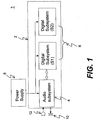
- FIG. 1 shows a hearing aid 1 to which side effects reduction in accordance with an embodiment of the present invention is suitably applied.
- the hearing aid 1 contains an audio processing system 2 with at least one electronic circuit that incorporates an audio subsystem 4 (victim subsystem), and one or more digital subsystems 6 (one or more attacker subsystems).
- Each of the digital subsystems 6 is denoted by Sx, where "x" is the number of a particular subsystem.
- the audio subsystem 4 and the digital subsystems 6 are powered by a common power supply 8.
- the audio processing system 2 may include the other subsystems (Oz) which are characterized as non-sensitive to a variation of the power supply voltage and are not consuming a periodic dynamic current through the common power supply 8.
- the audio subsystem 4 may include an analog-to-digital (A/D) converter as a minimum and can optionally include amplification units, aliasing filtering units, digital-to-analog (D/A) conversion units, wireless receiver/transmitter or combinations thereof. Some of the subsystems listed above are by nature sensitive to variations in the power supply voltage.
- the A/D converter converts an analog audio signal to digital samples at one or more sampling frequencies.
- the hearing aid 1 may further contain audio transducers, such as microphone and receiver, trimmers, and other input/output (I/O) related components specific for the actual hearing aid.
- a loud speaker 10 and a microphone 12 are shown.
- An audio signal from the surrounding environment enters the microphone 12 where it is converted to an electrical signal. Subsequently this electrical signal is directed to the audio subsystem 4.
- the audio subsystem 4 performs signal conditioning and analog to digital (A/D) conversion.
- the digitized audio signal is subsequently directed to either of the signal processing subsystems S1 and S2, where it is processed according to a processing scheme, and subsequently directed back to the audio subsystem 4.
- the signal processed in the audio processing system 2 is converted to a representation suitable for producing the desired audio signal in the hearing aid loud speaker 10.
- Each of the subsystems S1 and S2 may include one of the following functional entities: one or more digital signal processors (DSPs) that process packets of data (e.g., audio, control signals, other type of signal); one or more dedicated digital co-processors that process packets of data (e.g., audio, control signals, other type of signal); one or more memory blocks (e.g., random access memory (RAM), read only memory (ROM), one or more fixed-functions (e.g., fast Fourier transform (FFT), discrete cosine transform (DCT), filters).
- DSPs digital signal processors
- DSPs digital signal processors
- dedicated digital co-processors that process packets of data (e.g., audio, control signals, other type of signal)
- memory blocks e.g., random access memory (RAM), read only memory (ROM), one or more fixed-functions (e.g., fast Fourier transform (FFT), discrete cosine transform (DCT), filters.
- the co-processor may
- Each data packet processed in the subsystems S1 and S2 may be a single audio sample, a block of audio samples, or a single sample or block of other type of data.
- the frequency of each block will be a submultiple of the frequency of the single sample frequency.
- the time period for processing a block is also referred to as a processing window.
- Figure 2 is a diagram showing one example of dynamic current when the side effects reduction is not applied to the system of Figure 1 .
- Processing of data packets is associated with drawing current from the power supply 8.
- "36" and “38” represent processing windows (i.e., the time periods t 1 and t 2 at which processing events are performed inside the subsystems S1 and S2) for the subsystems S1 and S2, respectively.
- the processing window determines the maximum time period in which a sample, or a block of samples, has to be processed.
- a processing window is periodic in nature.
- the amount of processing performed inside a processing window for a given subsystem (Sx) is referred to as the load (Lx) for that subsystem (Sx).
- Lx the load for that subsystem (Sx).
- L1 is the load for subsystem S1
- L2 is the load for subsystem S2.
- the load Lx for a given subsystem Sx inside a processing window includes one or more processing events.
- the load is normally associated with the amount of data being subject to computations and the number of memory accesses performed. However, this correlation is not a requirement. In general, the more processing of data completed and the more memory accesses the higher the load and therefore the higher the amplitude of the dynamic current consumption for a particular subsystem.
- the properties of the dynamic current can be viewed in at least two ways.
- the amplitude variation over time and the amplitude variation over frequency are referred to as dynamic current waveform.
- the amplitude variation over frequency is referred to as dynamic current spectrum.
- the dynamic current spectrum may be obtained from the dynamic current waveform by means of a fast-Fourier transformation or similar transformation.
- Each of the dynamic current waveforms 30 and 32 shows the amplitude of the dynamic current as a function of time.
- the dynamic current waveform 30 is for the processing window 36 of one subsystem S1
- the dynamic current waveform 32 is for the processing window 38 of the subsystem S2.
- the fundamental frequency of the dynamic current waveform 32 is higher than the fundamental frequency of the dynamic current waveform 30.
- the spectrum for the dynamic current waveform 32 has a higher fundamental frequency than the spectrum for the dynamic current waveform 30.
- DCSP Dynamic Current Spectrum Property
- the level of undesired noise is related to the spectral properties of the dynamic current consumed in the audio processing system 2 that contains the subsystems, where noise encapsulates all undesired audible side effects.
- the embodiment of the present invention provides a method of reducing undesired audible side effects by changing DCSP(s) of the dynamic current.
- the DCSP of the dynamic current may be changed at least two different ways: by changing frequency, by changing amplitude of the dynamic current waveform or a combination thereof, in accordance with the definition of DCSP.
- IAB In-Audio-Band
- OAB Out-of-Audio-Band
- the IAB dynamic current is defined as dynamic current with a fundamental frequency that lies within the audio band of interest for the input and/or output signals. In this case, undesired audio side effects will occur inside the audio band of interest.
- the OAB dynamic current is defined as dynamic current with a fundamental frequency that lies outside the audio band of interest for the input and/or output signals. In this case, undesired audio artifacts will occur outside the audio band of interest.
- the undesired audible side effects are proportional to the amplitude of the dynamic current audible side effect.
- Figure 3 is a diagram showing one example of processing events when the side effects reduction is not applied to the system of Figure 1 .
- "42", "44” and "46” represent processing events within the processing window 36 for the subsystem S1 of Figure 1 .
- the load L1 inside the processing window 36 for the subsystem S1 includes three processing events 42, 44, and 46 executed immediately after each other.
- Each of the processing events 42, 44, 46 represents some necessary amount of processing (i.e., instruction execution and memory accesses).
- the dynamic current Since the processing events 42, 44, and 46 are executed immediately after each other, the dynamic current has a fundamental frequency equal to the period of the processing window 36. If this fundamental frequency results in an IAB dynamic current when the processing events 42, 44 and 46 are executed, then undesired audible audible side effects may be induced into the audio subsystem (4 of Figure 1 ).
- the processing window 36 has a time duration of 30 clock cycles; and each of three processing events 42, 44, and 46 takes 5 clock cycles to execute.
- the processing event 42 is executed during cycles 1-5, the processing event 44 is executed during cycles 6-10, and the processing event 46 is executed during cycles 11-15.
- the load L1 includes one, two or more than three processing events within a processing window.
- Changing DCSP(s) influences the execution of processing events (e.g., 42-46 of Figure 3 ) within a processing window (e.g., 36 of Figure 3 ) for a given digital subsystem (e.g., S1, S2 or S1 and S2 of Figure 1 ).
- a processing window e.g., 36 of Figure 3
- a given digital subsystem e.g., S1, S2 or S1 and S2 of Figure 1
- an IAB dynamic current is transformed to an OAB dynamic current (change of frequency); the amplitude of the dynamic current is transformed from audible to inaudible (change of amplitude); or a combination thereof.
- Changing DCSP(s) is implemented by the method of: (1) an Interleaved Execution of Processing Events; (2) a Slowed Execution of Processing Events; (3) an Execution of Dummy Processing Events; (4) a Random Delayed Execution of Processing Events; or (5) combinations thereof.
- the DCSP change methods (1)-(5) affect one or more than one of the DCSPs.
- the DCSP method (1) may be chosen for an application where there are no strict requirements as to when processing events are executed within a processing window, i.e., changing the instants in time at which processing events occur within a processing window does not adversely affect the application.
- the DCSP method (2) may be chosen for an application where the duration of the execution event is not critical, i.e., extended duration of a processing event within a processing window does not adversely affect the application.
- the DCSP method (3) may be chosen for an application where timing and duration of processing events within a processing window are critical, i.e., where the instants in time or duration of processing events within a processing window cannot be changed.
- the DCSP method (4) may be chosen for an application where the timing of processing events across processing windows is not critical, i.e., where one processing event may be executed at an instant in time within one processing window and at a second, different instant in time in a second processing window.
- Two or more than two DCSP methods may be chosen as the DCSP method (5).
- the audio processing system 2 may include module for implementing one or more than one of the DCSP change methods (1)-(5).
- One or more digital subsystems may contain the module for implementing the DCSP change methods (1)-(5).
- the module may selectively implement the DCSP change methods (1)-(5).
- the DCSP of the dynamic current waveform for a particular subsystem is modified by changing the interleaving properties of one or more processing events inside a processing window for that subsystem.
- the interleaving properties include the time intervals between the processing events within the processing window.
- the DCSP change method adjusts the timing of each processing event (e.g., 42, 44, 46) in a processing window (e.g., 36).
- the processing events are spread out with a certain time interval inside the processing window.
- the dynamic current is changed from IAB to OAB.
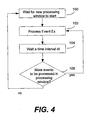
- Figure 4 is a flow chart showing one example of operation for the Interleaved Execution of Processing Events.
- the digital subsystem Sx (e.g., S1, S2 or S1 and S2 of Figure 1 ) waits for start of a new processing window (step 100). In the new processing window, one or more than one processing event Ex is processed (step 102) in the subsystem Sx.
- the digital subsystem Sx waits a time interval dt (step 104). It is determined whether there is any event(s) to be processed in the processing window (step 106). If yes, the digital subsystem Sx retunes to step 102. If no, the digital subsystem Sx returns to step 100.
- Figure 5 is a diagram showing one example of the Interleaved Execution of Processing Events.
- the processing events 42, 44 and 46 in the processing window 36 for the subsystem S1 are executed as illustrated in Figure 5 .
- the processing event 42 is executed during cycles 1-5
- the processing event 44 is executed during cycles 11-15
- the processing event 46 is executed during cycles 21-25.
- adding the time intervals between the processing events 42 and 44 and between the processing events 44 and 46 results in the fundamental frequency of the dynamic current waveform to be changed after interleaving is performed. In this example, it is increased by a factor of three, which may be sufficient to bring the dynamic current waveform from IAB to OAB. For example, if the fundamental frequency is 4 kHz before interleaving it will now be 12 kHz after applying interleaving, which is deemed to be OAB in the intended application.
- the fundamental frequency for the dynamic current waveform 30 for the subsystem S1 is increased by spreading out the processing events 42, 44 and 46. It causes the frequency of the dynamic current to be changed since there are now three peaks in the dynamic current waveform instead of one as in the original case (the frequency triples).
- the fundamental frequency of the dynamic current is transformed into a higher frequency.
- an IAB dynamic current is transformed into an OAB dynamic current. If the fundamental frequency of the noise is equal to 4 kHz, which is IAB in the intended application, the modified fundamental frequency of the noise is moved to 12 kHz, which is OAB in the intended application.
- the DCSP of the dynamic current waveform for a particular subsystem is changed by lengthening the duration of one or more processing events inside a processing window for that subsystem. For example, the duration is increased so as to perform the desired amount of processing for a given processing event over a longer period of time. As such, the amplitude of the dynamic current waveform is reduced.
- Figure 6 is a flow chart showing one example of operation for the Slowed Execution of Processing Events.
- the digital subsystem Sx (e.g., S1, S2 or S1 and S2 of Figure 1 ) waits for start of a new processing window (step 110).
- a new processing window one or more than one processing event Ex is executed over a time interval dt (step 112) in the digital subsystem Sx. It is determined whether there is any event(s) to be processed in the processing window (step 114). If yes, the digital subsystem Sx retunes to step 112. If no, the digital subsystem Sx returns to step 110.
- Figure 7 is a diagram showing one example of the Slowed Execution of Processing Events.
- the processing events 42, 44 and 46 in the processing window 36 for the subsystem S1 are executed as illustrated in Figure 7 .
- the processing event 42 is executed during cycles 1-5
- the processing event 44 is executed during cycles 6-10
- the processing event 46 is executed during cycles 11-15.
- the original durations B1, B2 and B3 for the processing events 42, 44 and 46 are longer to (B1+ ⁇ 1), (B2+ ⁇ 2) and (B3+ ⁇ 3), respectively.
- the amplitude for the dynamic current waveform 30 for the subsystem S1 gets reduced distributing each processing event 42, 44 and 46 inside the processing window 36 over a larger amount of time.
- the frequency of a clock is changed.
- the frequency of a clock is half as the original frequency.
- the processing events 42, 44 and 46 take 15 cycles within the processing window.
- the amount of operations still takes 15 cycles.
- the 15 cycles are executed over a time interval that is twice as the original. This changes the DCSP(s) by reducing the amplitude of the associated dynamic current waveform.
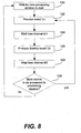
- Figure 8 is a flow chart showing one example of operation for the Execution of Dummy Processing Events.
- the digital subsystem Sx (e.g., S1, S2, or S1 and S2 of Figure 1 ) waits for start of a new processing window (step 120). In the new processing window, one or more than one processing event Ex is executed (step 122). The digital subsystem Sx waits a time interval dt1(step 124). Then, one or more than one dummy event Dx (step 126) is processed in the digital subsystem Sx. The digital subsystem Sx waits a time interval dt2 (step 128). It is determined whether there is any event(s) to be processed in the processing window (step 130). If yes, the digital subsystem Sx retunes to step 122. If no, the digital subsystem Sx returns to step 120.
- the frequency of the dynamic current waveform is increased.
- the amplitude of the dynamic current waveform may also be reduced.
- a dummy processing event is generated by having the subsystem in question execute operations that may not be needed for the application but are only inserted to increase the frequency and/or reduce the amplitude of the dynamic current waveform.
- Figure 9 is a diagram showing one example of the Execution of Dummy Processing Events.
- the processing event 42 is executed during cycles 1-5
- the processing event 44 is executed during cycles 6-10
- the processing event 46 is executed during cycles 11-15.
- dummy events 48 and 50 are executed within the processing window 36 after the event 46 with a certain interval.
- the frequency of the dynamic current waveform 30 for the subsystem S1 is increased by executing the two dummy processing events 48 and 50 in the processing window 36.
- the dummy processing event may include a processing event executed by the subsystem S1, which may or may not be related to the other processing events 42, 44, and 46.
- the number and durations of the dummy events shall be considered as fully configurable (which affects the frequency of the dynamic current waveform).
- the load related to each dummy processing event is fully configurable (affects the amplitude of the dynamic current waveform). For example, if the dummy processing event 48 represents a load that contains an amount of operations O1 and the dummy processing event 50 contains an amount of operations 02 and O2>O1 then 50 has a higher load. For example, two multiplications in a subsystem will consume more current than 1 multiplication in that same subsystem.
- the dummy processing event may include a processing event executed by the subsystem S2 of Figure 1 , which may or may not be related to the processing events 42, 44 and 46 executed by the subsystem S1 of Figure 1 .
- the number and durations of the dummy events from other subsystems are fully configurable.
- the load related to each dummy processing event from other subsystems is fully configurable.
- start timing and stop timing and load of the dummy events are configurable.
- the number of cycles between an event and a dummy event can be configured by simply setting the count between the two types of events.
- the IAB dynamic current is transformed into OAB dynamic current. Furthermore, by reducing the load of the dummy event, the amplitude of the dynamic current waveform is reduced.
- the signal processing algorithm is repartitioned so that processing that can be executed on a digital subsystem replaces a dummy event.
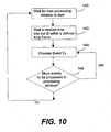
- Figure 10 is a flow chart showing one example of operation for the Random Delayed Execution of Processing Events.
- the digital subsystem Sx (e.g., S1, S2 or S1 and S2 of Figure 1 ) waits for start of a new processing window (step 140). In the new processing window, the digital subsystem Sx waits a random time interval dt within a defined time frame (step 142). A processing event Ex is executed (step 144). It is determined whether there is any event(s) to be processed in the processing window (step 146). If yes, the digital subsystem Sx retunes to step 144. If no, the digital subsystem Sx returns to step 140.
- a processing event Ex is executed (step 144). It is determined whether there is any event(s) to be processed in the processing window (step 146). If yes, the digital subsystem Sx retunes to step 144. If no, the digital subsystem Sx returns to step 140.
- the duration between the events from one processing window to the next varies randomly, i.e. the duration between events in one processing window and the similar events in the following processing window vary across processing windows.
- the variations in the random delays are provided such that three processing events 42, 44 and 46 are all executed within a given processing window.
- the delay may be provided by a random generator that counts a random number of cycles (within the specified boundaries) between a processing event in one processing window and the similar processing event in the following window.
- the delay boundary is determined such that a processing event can always be executed within the desired processing window. If the delay is larger than the boundary, the processing event would not be processed within the desired processing window, but would have to be executed in the following processing window, which would result in erroneous execution of said processing event.
- the frequency properties of the events are not fixed, i.e., there is no fixed interval between events 42, 44 and 46 from processing window to the events 42, 44 and 46 in the following processing window and thus no periodic behavior that will result in a periodic dynamic current and as such a high-amplitude fundamental frequency that is IAB.
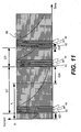
- Figure 11 is a diagram showing one example of the Random Delayed Execution of Processing Events.
- the value of d r (t) is a random or pseudo-random value between 0 and t 1 -t p (the processing period minus the processing time).
- t 1 is also known as the time duration of the processing window. Because the time t r (t) between the start of two sets of processing events in two subsequent processing windows is not constant, and varies between 0 and 2*t 1 -2*t p , the spectrum of the dynamic current waveform is changed. The fundamental frequency of the noise is not constant, and is constantly moved between 0 and 1/(2*t 1 -2*t p ) across processing windows. The overall result of the random delay insertion is a dispersal of the noise energy in several bands of energy. The noise is more a "white" noise.
- a random delay may be the result of having a counter that counts a random number of clock cycles (the random number being constrained by a set of boundaries).
- Figures 12(a)-(d) are graphs showing one example of the effect of the Random Delayed Execution of Processing Events on the hearing aid 1 of Figure 1 .
- Figures 12(a) and (b) are related, and Figures(c) and (d) are related.
- Figure 12(a) shows processing events and the associated dynamic current waveforms.
- Figure 12(b) shows the spectrum (frequency vs. amplitude) of the dynamic current waveform.
- Figure 12(c) shows the processing events plus dynamic current waveform after the random delayed execution method has been applied.
- Figure 12(d) shows the spectrum of the dynamic current waveform after the Random Delayed Execution of Processing Events has been applied.
- FIG 1 two digital subsystems S1 and S2 are shown.
- the side effects reduction in accordance with the embodiment(s) of the present invention is applicable to a system having any number of subsystems.
- the audio processing system 2 may include more than two digital subsystems.
- Figure 13 shows the hearing aid 1a that includes an audio processing system 2a.
- the audio processing system 2a includes digital subsystems S1, S2, ..., Sn, where "n" corresponds to the subsystem number and greater than 2.
- the digital subsystems S1, S2, ..., Sn and the audio subsystem 4 share the power supply 8.
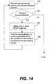
- Figure 14 shows one example of an operation for reorganizing the processing events of the audio processing system (2 of Figure 1 , 2a of Figure 13 ).
- the reorganization process according to Figure 14 is performed during the development of the audio processing system (2, 2a). It is assumed that an application P1 (or program) is in the audio processing system, and a plurality of processing events are defined in the application P1.
- the audio processing system executes the processing events as they are implemented.
- an application developer monitors dynamic current consumption in the audio processing system (step 150). Based on the monitoring, the developer determines whether the dynamic current of the audio processing system is audible (step 152). If yes, the developer selects one or more than one DCSP method (step 154), which will apply to the processing events within all of the processing windows.
- the application P1 is transferred to a new application P2 (step 156), which contains P1 with the selected DCSP method(s). In the new application P2, the processing events are reorganized by the selected DCSP method(s).
- the reorganized processing events are executed as they are implemented.
- the developer monitors dynamic current consumption in the audio processing system (step 150). Based on the monitoring, the developer determines whether the dynamic current of the audio processing system is audible (step 152). If yes, the developer selects one or more than one DCSP method (step 154), which will apply to the processing events within all of the processing windows.
- the application P2 is transferred to a new application P3 (step 156) where the processing events are reorganized by the newly selected DCSP method(s).
- the executing/monitoring step, the determining step, the selecting step and the transferring step are repeated until undesired audible artefacts are reduced to a certain level.
- the developer may listen to audible outputs from the speaker (10 of Figures 1 and 13 ) to find audible artefacts.
- a system 15 may be provided to the hearting aid 1 to calibrate the audio processing system 2a (or 2 of Figure 1 ).
- the monitoring and determining steps may be automatically performed by the system 15.
- the system 15 may adjust the threshold to determine whether there are undesired audible artefacts.
- the selecting step may be automatically performed by the system 15.
- the system 15 may adjust the time interval of Figure 4 , the time interval of Figure 6 , the configuration of the dummy events of Figure 8 , the random time interval of Figure 10 or combinations thereof.
- the system 15 may have a memory to store the time interval of Figure 4 , the time interval of Figure 6 , the configuration of the dummy events of Figure 8 , the random time interval of Figure 10 , or combinations thereof.
- the steps of Figure 14 may be performed in a listening device (e.g., 2 of Figure 1 , 2a of Figure 13 ), or in a design environment during the design process.
- a listening device e.g., 2 of Figure 1 , 2a of Figure 13
- a design environment during the design process.
- the side effects reduction of the present invention may be implemented in any of the digital subsystems that take part of the system.
- Parameters for the DCSP method are configurable and may be downloaded to the system upon initialization.
- these configuration parameters may be stored in a non-volatile memory and downloaded to the configuration portion of a given subsystem upon battery insertion in the device.
- the side effects reduction of the present invention may be implemented during the design process of the audio processing systems.
- Parameters for the DCSP method may be obtained, used, and refined for the design.
- a listening device will be adaptive to the usage and the environment of the device, and implement one, or more than one of the methods described above during the usage.
- the side effects reduction of the present invention may be implemented by any hardware, software or a combination of hardware and software having the above described functions.
- the software code either in its entirety or a part thereof, may be stored in a computer readable medium.
- a computer data signal representing the software code which may be embedded in a carrier wave may be transmitted via a communication network.
- Such a computer readable medium and, a computer data signal and carrier wave are also within the scope of the present invention as defined in the appended claims, as well as the hardware, software and the combination thereof.
Landscapes
- Physics & Mathematics (AREA)
- Engineering & Computer Science (AREA)
- Acoustics & Sound (AREA)
- Signal Processing (AREA)
- Health & Medical Sciences (AREA)
- General Health & Medical Sciences (AREA)
- Otolaryngology (AREA)
- Neurosurgery (AREA)
- Circuit For Audible Band Transducer (AREA)
- Amplifiers (AREA)
- Mobile Radio Communication Systems (AREA)
- Stereophonic System (AREA)
Claims (26)
- Procédé pour réduire les effets latéraux audibles de consommation d'un courant dynamique pour un dispositif d'écoute ayant une pluralité de sous-systèmes (6, S1, S2), le procédé comprenant les étapes consistant à :exécuter une pluralité d'événements de traitement dans un sous-système (6, S1, S2), les événements de traitement étant périodiques ;surveiller le courant dynamique provoqué par un ou par plus d'un événement de traitement, etréorganiser un ou plus d'un événement de traitement pour changer une propriété de spectre de courant dynamique associé au courant dynamique, dans lequel la propriété du spectre de courant dynamique est la caractéristique d'un spectre associé à une forme d'onde de courant dynamique d'un sous-système (6, S1, S2).
- Procédé selon la revendication 1, dans lequel l'étape de réorganisation inclut l'étape consistant à :changer une propriété d'entrelacement pour ledit un ou plus d'un événement de traitement, dans lequel la propriété d'entrelacement inclut les intervalles temporels entre les événements de traitement à l'intérieur d'une fenêtre de traitement.
- Procédé selon la revendication 2, dans lequel l'étape de réorganisation change un intervalle temporel entre les événements de traitement.
- Procédé selon la revendication 1, dans lequel l'étape de réorganisation inclut l'étape consistant à :allonger un temps de traitement pour chacun dudit un ou desdits plus d'un événement de traitement.
- Procédé selon la revendication 4, dans lequel l'étape d'allongement augmente une durée de chacun desdits un ou plus d'un événement de traitement.
- Procédé selon la revendication 1, dans lequel l'étape de réorganisation inclut l'étape consistant à :exécuter un ou plus d'un événement de traitement factice.
- Procédé selon la revendication 6, dans lequel le nombre, la durée ou le nombre et la durée des événements de traitement factice est/sont configurable(s).
- Procédé selon la revendication 6, dans lequel l'événement de traitement factice est un événement de traitement dans l'un quelconque des sous-systèmes (6, S1, S2).
- Procédé selon la revendication 1, dans lequel l'étape de réorganisation inclut l'étape consistant à :insérer un retard aléatoire avant d'exécuter lesdits un ou plus d'un événement de traitement.
- Procédé selon la revendication 1, dans lequel l'étape de réorganisation inclut l'étape consistant à :insérer un retard pseudo-aléatoire avant d'exécuter lesdits un ou plus d'un événement de traitement.
- Procédé selon la revendication 1, comprenant en outre l'étape consistant à :stocker un paramètre qui est utilisé à l'étape de réorganisation.
- Procédé selon la revendication 1, dans lequel le procédé est exécuté pour un dispositif d'écoute in situ.
- Procédé selon la revendication 1, dans lequel le procédé est exécuté pendant un processus de développement, un processus de conception, ou une combinaison de ceux-ci.
- Système pour réduire les effets latéraux audibles d'une consommation de courant dynamique pour un système audio ayant une pluralité de sous-systèmes (6, S1, S2), le système comprenant :un module pour surveiller un courant dynamique provoqué par un ou plusieurs événements de traitement mis en oeuvre dans un ou plus d'un sous-système (6, S1, S2), etun module pour réorganiser un ou plus d'un événement de traitement pour changer une propriété de spectre de courant dynamique associé au courant dynamique,dans lequel la propriété du spectre de courant dynamique est la caractéristique d'un spectre associé à une forme d'onde dynamique d'un sous-système (6, S1, S2).
- Système selon la revendication 14, dans lequel le système audio comprend en outre un transducteur d'entrée, un transducteur de sortie, ou une combinaison de ceux-ci.
- Système selon la revendication 14, dans lequel le module pour la réorganisation est capable de modifier une exécution entrelacée desdits un ou plus d'un événement de traitement.
- Système selon la revendication 14, dans lequel le module pour la réorganisation est capable de ralentir l'exécution de l'un au moins des événements de traitement.
- Système selon la revendication 14, dans lequel le module pour la réorganisation est capable d'exécuter un ou plus d'un événement de traitement factice.
- Système selon la revendication 14, dans lequel le module pour la réorganisation est capable de retarder l'exécution de l'un au moins des événements de traitement.
- Système selon la revendication 14, dans lequel le module pour la réorganisation inclut l'un au moins des modules suivants :un module pour modifier une exécution entrelacée de l'un au moins des événements de traitement ;un module pour ralentir l'exécution de l'un au moins des événements de traitement ;un module pour exécuter au moins un événement de traitement factice ;un module pour retarder de façon aléatoire l'exécution de l'un au moins des événements de traitement.
- Système selon la revendication 14, dans lequel le module de surveillance surveille la sortie des signaux audio depuis le système audio.
- Produit de programme d'ordinateur, comprenant :une mémoire ayant un code lisible à l'ordinateur incorporé dans elle-même destiné à réduire les effets latéraux audibles de consommation de courant dynamique pour un appareil d'écoute ayant une pluralité de sous-systèmes (6, S1, S2), comprenant :un code pour définir une pluralité d'événements de traitement exécutés dans un ou plus d'un des sous-systèmes (6, S1, S2) ; etun code pour réorganiser un ou plus d'un des événements de traitement à l'égard de la temporisation d'exécution, de la durée d'exécution ou d'une combinaison de celles-ci pour changer une propriété de spectre de courant dynamique associé au courant dynamique provoqué par un ou plus d'un des événements de traitement,dans lequel la propriété du spectre de courant dynamique est la caractéristique d'un spectre associé à une forme d'onde de courant dynamique d'un sous-système (6, S1, S2).
- Produit de programme d'ordinateur selon la revendication 22, dans lequel le code de réorganisation inclut l'un au moins des codes suivants :un code pour changer une propriété d'entrelacement pour un ou plus d'un des événements de traitement, dans lequel la propriété d'entrelacement inclut les intervalles temporels entre les événements de traitement à l'intérieur d'une fenêtre de traitement ;un code pour allonger la durée pour chacun des un ou plus d'un événement de traitement ;un code pour exécuter un ou plus d'un événement de traitement factice ; etun code pour exécuter un retard aléatoire avant d'exécuter un ou plus d'un des événements de traitement.
- Procédé selon la revendication 1, dans lequel l'étape de surveillance surveille une sortie des signaux audio provenant du dispositif d'écoute.
- Procédé selon la revendication 1, comprenant en outre l'étape consistant à télécharger des paramètres de configuration associés à la réorganisation vers le dispositif d'écoute lors de l'initialisation.
- Système selon la revendication 14, comprenant en outre une mémoire pour stocker des paramètres de configuration associés à la réorganisation.
Applications Claiming Priority (2)
| Application Number | Priority Date | Filing Date | Title |
|---|---|---|---|
| CA002462463A CA2462463A1 (fr) | 2004-03-30 | 2004-03-30 | Methode et systeme de reduction des effets secondaires audibles de la consommation dynamique de courant |
| CA2462463 | 2004-03-30 |
Publications (4)
| Publication Number | Publication Date |
|---|---|
| EP1585362A2 EP1585362A2 (fr) | 2005-10-12 |
| EP1585362A3 EP1585362A3 (fr) | 2012-07-04 |
| EP1585362B1 true EP1585362B1 (fr) | 2018-11-28 |
| EP1585362B8 EP1585362B8 (fr) | 2019-01-23 |
Family
ID=34891811
Family Applications (1)
| Application Number | Title | Priority Date | Filing Date |
|---|---|---|---|
| EP05006949.1A Expired - Lifetime EP1585362B8 (fr) | 2004-03-30 | 2005-03-30 | Procédé, système et produit programme d'ordinateur pour réduire les effets secondaires dûs à la consommation de courant dynamique |
Country Status (5)
| Country | Link |
|---|---|
| US (1) | US7693294B2 (fr) |
| EP (1) | EP1585362B8 (fr) |
| CA (2) | CA2462463A1 (fr) |
| DK (1) | DK1585362T3 (fr) |
| WO (1) | WO2005096668A1 (fr) |
Families Citing this family (2)
| Publication number | Priority date | Publication date | Assignee | Title |
|---|---|---|---|---|
| EP1883273A1 (fr) * | 2006-07-28 | 2008-01-30 | Siemens Audiologische Technik GmbH | Appareil de commande et procédé destiné à la transmission sans fil de signal audio dans le cadre d'une programmation d'appareil auditif |
| WO2020055923A1 (fr) * | 2018-09-11 | 2020-03-19 | Knowles Electronics, Llc | Microphone numérique à bruit de traitement réduit |
Family Cites Families (9)
| Publication number | Priority date | Publication date | Assignee | Title |
|---|---|---|---|---|
| AU596633B2 (en) | 1986-01-21 | 1990-05-10 | Antin, Mark | Digital hearing enhancement apparatus |
| CA2025012A1 (fr) | 1989-09-11 | 1991-03-12 | William R. Short | Systeme de reduction des bruits audibles |
| US5953237A (en) * | 1996-11-25 | 1999-09-14 | Hewlett-Packard Company | Power balancing to reduce step load |
| US6498858B2 (en) * | 1997-11-18 | 2002-12-24 | Gn Resound A/S | Feedback cancellation improvements |
| US7110839B2 (en) * | 2000-10-02 | 2006-09-19 | Harman International Industries, Incorporated | Audio system for minimizing the chance that high power audio signals may be directed to a headphone jack |
| TW497093B (en) | 2001-03-22 | 2002-08-01 | Realtek Semiconductor Corp | Audio frequency signal processor and method thereof |
| US7000138B1 (en) * | 2001-06-07 | 2006-02-14 | Cirrus Logic, Inc | Circuits and methods for power management in a processor-based system and systems using the same |
| US20060063495A1 (en) * | 2004-09-21 | 2006-03-23 | Intel Corporation | Mitigation of electromagnetic interference |
| US7685458B2 (en) * | 2006-12-12 | 2010-03-23 | Kabushiki Kaisha Toshiba | Assigned task information based variable phase delayed clock signals to processor cores to reduce di/dt |
-
2004
- 2004-03-30 CA CA002462463A patent/CA2462463A1/fr not_active Abandoned
-
2005
- 2005-03-28 US US11/091,743 patent/US7693294B2/en active Active
- 2005-03-29 CA CA2561881A patent/CA2561881C/fr not_active Expired - Lifetime
- 2005-03-29 WO PCT/CA2005/000459 patent/WO2005096668A1/fr not_active Ceased
- 2005-03-30 DK DK05006949.1T patent/DK1585362T3/en active
- 2005-03-30 EP EP05006949.1A patent/EP1585362B8/fr not_active Expired - Lifetime
Non-Patent Citations (1)
| Title |
|---|
| None * |
Also Published As
| Publication number | Publication date |
|---|---|
| CA2561881C (fr) | 2012-11-13 |
| US7693294B2 (en) | 2010-04-06 |
| EP1585362B8 (fr) | 2019-01-23 |
| EP1585362A2 (fr) | 2005-10-12 |
| WO2005096668A1 (fr) | 2005-10-13 |
| DK1585362T3 (en) | 2019-03-25 |
| EP1585362A3 (fr) | 2012-07-04 |
| US20050234711A1 (en) | 2005-10-20 |
| CA2462463A1 (fr) | 2005-09-30 |
| CA2561881A1 (fr) | 2005-10-13 |
Similar Documents
| Publication | Publication Date | Title |
|---|---|---|
| EP2226794B1 (fr) | Estimation du bruit de fond | |
| CN107645697B (zh) | 用作回声消除器的自适应滤波器单元 | |
| TWI463817B (zh) | 可適性智慧雜訊抑制系統及方法 | |
| JP6351538B2 (ja) | ディジタル音響信号用の多帯域信号プロセッサ | |
| EP1121834A2 (fr) | Protheses auditives fonctionnant d'apres des modeles de compression cochleaire | |
| US8948424B2 (en) | Hearing device and method for operating a hearing device with two-stage transformation | |
| US8422708B2 (en) | Adaptive long-term prediction filter for adaptive whitening | |
| US7957543B2 (en) | Listening device | |
| CN112565981A (zh) | 啸叫抑制方法、装置、助听器及存储介质 | |
| US20190392849A1 (en) | Systems and methods for processing an audio signal for replay on an audio device | |
| CN117392994A (zh) | 一种音频信号处理方法、装置、设备及存储介质 | |
| CN112954576B (zh) | 基于滤波器组的数字助听器啸叫检测与抑制算法及硬件实现方法 | |
| EP2148526A1 (fr) | Modification de contenu spectral pour évaluation de canal de réponse robuste | |
| EP1585362B1 (fr) | Procédé, système et produit programme d'ordinateur pour réduire les effets secondaires dûs à la consommation de courant dynamique | |
| US11062717B2 (en) | Systems and methods for processing an audio signal for replay on an audio device | |
| CN115713942A (zh) | 音频处理方法、装置、计算设备及介质 | |
| US9124963B2 (en) | Hearing apparatus having an adaptive filter and method for filtering an audio signal | |
| EP3240276A1 (fr) | Dispositif et procédé d'annulation du bruit dans un signal reçu | |
| Negi et al. | Comparative Analysis of Octave and Band Pass Filter for Improving Hearing Capability of Deaf People | |
| US20250080909A1 (en) | Audio signal processing method and apparatus, storage medium, and vehicle | |
| Choy et al. | Subband-based acoustic shock limiting algorithm on a low-resource dsp system | |
| JP2024532982A (ja) | スピーカの消費電力制御方法、装置、記憶媒体及び電子機器 | |
| JPWO2023084470A5 (fr) | ||
| JP2010171674A (ja) | 補聴器 | |
| HK1222478B (en) | Frequency band compression with dynamic thresholds |
Legal Events
| Date | Code | Title | Description |
|---|---|---|---|
| PUAI | Public reference made under article 153(3) epc to a published international application that has entered the european phase |
Free format text: ORIGINAL CODE: 0009012 |
|
| 17P | Request for examination filed |
Effective date: 20050330 |
|
| AK | Designated contracting states |
Kind code of ref document: A2 Designated state(s): AT BE BG CH CY CZ DE DK EE ES FI FR GB GR HU IE IS IT LI LT LU MC NL PL PT RO SE SI SK TR |
|
| AX | Request for extension of the european patent |
Extension state: AL BA HR LV MK YU |
|
| RIN1 | Information on inventor provided before grant (corrected) |
Inventor name: DROLLINGER, ANDREAS Inventor name: SCHNEIDER, TODD Inventor name: MATTHEY, MARC Inventor name: NIELSEN, JAKOB |
|
| PUAL | Search report despatched |
Free format text: ORIGINAL CODE: 0009013 |
|
| AK | Designated contracting states |
Kind code of ref document: A3 Designated state(s): AT BE BG CH CY CZ DE DK EE ES FI FR GB GR HU IE IS IT LI LT LU MC NL PL PT RO SE SI SK TR |
|
| AX | Request for extension of the european patent |
Extension state: AL BA HR LV MK YU |
|
| RIC1 | Information provided on ipc code assigned before grant |
Ipc: H04R 3/00 20060101AFI20120530BHEP Ipc: G06F 1/32 20060101ALI20120530BHEP Ipc: H04R 25/00 20060101ALI20120530BHEP |
|
| 17Q | First examination report despatched |
Effective date: 20130131 |
|
| AKX | Designation fees paid |
Designated state(s): AT BE BG CH CY CZ DE DK EE ES FI FR GB GR HU IE IS IT LI LT LU MC NL PL PT RO SE SI SK TR |
|
| RAP1 | Party data changed (applicant data changed or rights of an application transferred) |
Owner name: SEMICONDUCTOR COMPONENTS INDUSTRIES, LLC |
|
| GRAP | Despatch of communication of intention to grant a patent |
Free format text: ORIGINAL CODE: EPIDOSNIGR1 |
|
| STAA | Information on the status of an ep patent application or granted ep patent |
Free format text: STATUS: GRANT OF PATENT IS INTENDED |
|
| INTG | Intention to grant announced |
Effective date: 20180612 |
|
| GRAS | Grant fee paid |
Free format text: ORIGINAL CODE: EPIDOSNIGR3 |
|
| GRAA | (expected) grant |
Free format text: ORIGINAL CODE: 0009210 |
|
| STAA | Information on the status of an ep patent application or granted ep patent |
Free format text: STATUS: THE PATENT HAS BEEN GRANTED |
|
| AK | Designated contracting states |
Kind code of ref document: B1 Designated state(s): AT BE BG CH CY CZ DE DK EE ES FI FR GB GR HU IE IS IT LI LT LU MC NL PL PT RO SE SI SK TR |
|
| REG | Reference to a national code |
Ref country code: GB Ref legal event code: FG4D |
|
| REG | Reference to a national code |
Ref country code: CH Ref legal event code: EP |
|
| REG | Reference to a national code |
Ref country code: AT Ref legal event code: REF Ref document number: 1071687 Country of ref document: AT Kind code of ref document: T Effective date: 20181215 |
|
| RAP2 | Party data changed (patent owner data changed or rights of a patent transferred) |
Owner name: GN HEARING A/S |
|
| REG | Reference to a national code |
Ref country code: DE Ref legal event code: R096 Ref document number: 602005055045 Country of ref document: DE |
|
| REG | Reference to a national code |
Ref country code: IE Ref legal event code: FG4D |
|
| REG | Reference to a national code |
Ref country code: CH Ref legal event code: PK Free format text: BERICHTIGUNG B8 |
|
| REG | Reference to a national code |
Ref country code: CH Ref legal event code: PK Free format text: BERICHTIGUNGEN |
|
| RIC2 | Information provided on ipc code assigned after grant |
Ipc: H04R 3/00 20060101AFI20120530BHEP Ipc: H04R 25/00 20060101ALI20120530BHEP Ipc: G06F 1/32 20190101ALI20120530BHEP |
|
| REG | Reference to a national code |
Ref country code: DK Ref legal event code: T3 Effective date: 20190318 |
|
| REG | Reference to a national code |
Ref country code: NL Ref legal event code: MP Effective date: 20181128 |
|
| REG | Reference to a national code |
Ref country code: LT Ref legal event code: MG4D |
|
| REG | Reference to a national code |
Ref country code: AT Ref legal event code: MK05 Ref document number: 1071687 Country of ref document: AT Kind code of ref document: T Effective date: 20181128 |
|
| PG25 | Lapsed in a contracting state [announced via postgrant information from national office to epo] |
Ref country code: AT Free format text: LAPSE BECAUSE OF FAILURE TO SUBMIT A TRANSLATION OF THE DESCRIPTION OR TO PAY THE FEE WITHIN THE PRESCRIBED TIME-LIMIT Effective date: 20181128 Ref country code: FI Free format text: LAPSE BECAUSE OF FAILURE TO SUBMIT A TRANSLATION OF THE DESCRIPTION OR TO PAY THE FEE WITHIN THE PRESCRIBED TIME-LIMIT Effective date: 20181128 Ref country code: BG Free format text: LAPSE BECAUSE OF FAILURE TO SUBMIT A TRANSLATION OF THE DESCRIPTION OR TO PAY THE FEE WITHIN THE PRESCRIBED TIME-LIMIT Effective date: 20190228 Ref country code: LT Free format text: LAPSE BECAUSE OF FAILURE TO SUBMIT A TRANSLATION OF THE DESCRIPTION OR TO PAY THE FEE WITHIN THE PRESCRIBED TIME-LIMIT Effective date: 20181128 Ref country code: IS Free format text: LAPSE BECAUSE OF FAILURE TO SUBMIT A TRANSLATION OF THE DESCRIPTION OR TO PAY THE FEE WITHIN THE PRESCRIBED TIME-LIMIT Effective date: 20190328 Ref country code: ES Free format text: LAPSE BECAUSE OF FAILURE TO SUBMIT A TRANSLATION OF THE DESCRIPTION OR TO PAY THE FEE WITHIN THE PRESCRIBED TIME-LIMIT Effective date: 20181128 |
|
| PG25 | Lapsed in a contracting state [announced via postgrant information from national office to epo] |
Ref country code: PT Free format text: LAPSE BECAUSE OF FAILURE TO SUBMIT A TRANSLATION OF THE DESCRIPTION OR TO PAY THE FEE WITHIN THE PRESCRIBED TIME-LIMIT Effective date: 20190328 Ref country code: GR Free format text: LAPSE BECAUSE OF FAILURE TO SUBMIT A TRANSLATION OF THE DESCRIPTION OR TO PAY THE FEE WITHIN THE PRESCRIBED TIME-LIMIT Effective date: 20190301 Ref country code: SE Free format text: LAPSE BECAUSE OF FAILURE TO SUBMIT A TRANSLATION OF THE DESCRIPTION OR TO PAY THE FEE WITHIN THE PRESCRIBED TIME-LIMIT Effective date: 20181128 |
|
| PG25 | Lapsed in a contracting state [announced via postgrant information from national office to epo] |
Ref country code: NL Free format text: LAPSE BECAUSE OF FAILURE TO SUBMIT A TRANSLATION OF THE DESCRIPTION OR TO PAY THE FEE WITHIN THE PRESCRIBED TIME-LIMIT Effective date: 20181128 |
|
| PG25 | Lapsed in a contracting state [announced via postgrant information from national office to epo] |
Ref country code: PL Free format text: LAPSE BECAUSE OF FAILURE TO SUBMIT A TRANSLATION OF THE DESCRIPTION OR TO PAY THE FEE WITHIN THE PRESCRIBED TIME-LIMIT Effective date: 20181128 Ref country code: CZ Free format text: LAPSE BECAUSE OF FAILURE TO SUBMIT A TRANSLATION OF THE DESCRIPTION OR TO PAY THE FEE WITHIN THE PRESCRIBED TIME-LIMIT Effective date: 20181128 Ref country code: IT Free format text: LAPSE BECAUSE OF FAILURE TO SUBMIT A TRANSLATION OF THE DESCRIPTION OR TO PAY THE FEE WITHIN THE PRESCRIBED TIME-LIMIT Effective date: 20181128 |
|
| REG | Reference to a national code |
Ref country code: DE Ref legal event code: R097 Ref document number: 602005055045 Country of ref document: DE |
|
| PG25 | Lapsed in a contracting state [announced via postgrant information from national office to epo] |
Ref country code: SK Free format text: LAPSE BECAUSE OF FAILURE TO SUBMIT A TRANSLATION OF THE DESCRIPTION OR TO PAY THE FEE WITHIN THE PRESCRIBED TIME-LIMIT Effective date: 20181128 Ref country code: EE Free format text: LAPSE BECAUSE OF FAILURE TO SUBMIT A TRANSLATION OF THE DESCRIPTION OR TO PAY THE FEE WITHIN THE PRESCRIBED TIME-LIMIT Effective date: 20181128 Ref country code: RO Free format text: LAPSE BECAUSE OF FAILURE TO SUBMIT A TRANSLATION OF THE DESCRIPTION OR TO PAY THE FEE WITHIN THE PRESCRIBED TIME-LIMIT Effective date: 20181128 |
|
| PLBE | No opposition filed within time limit |
Free format text: ORIGINAL CODE: 0009261 |
|
| STAA | Information on the status of an ep patent application or granted ep patent |
Free format text: STATUS: NO OPPOSITION FILED WITHIN TIME LIMIT |
|
| PG25 | Lapsed in a contracting state [announced via postgrant information from national office to epo] |
Ref country code: SI Free format text: LAPSE BECAUSE OF FAILURE TO SUBMIT A TRANSLATION OF THE DESCRIPTION OR TO PAY THE FEE WITHIN THE PRESCRIBED TIME-LIMIT Effective date: 20181128 Ref country code: MC Free format text: LAPSE BECAUSE OF FAILURE TO SUBMIT A TRANSLATION OF THE DESCRIPTION OR TO PAY THE FEE WITHIN THE PRESCRIBED TIME-LIMIT Effective date: 20181128 |
|
| 26N | No opposition filed |
Effective date: 20190829 |
|
| PG25 | Lapsed in a contracting state [announced via postgrant information from national office to epo] |
Ref country code: LU Free format text: LAPSE BECAUSE OF NON-PAYMENT OF DUE FEES Effective date: 20190330 |
|
| REG | Reference to a national code |
Ref country code: BE Ref legal event code: MM Effective date: 20190331 |
|
| PG25 | Lapsed in a contracting state [announced via postgrant information from national office to epo] |
Ref country code: IE Free format text: LAPSE BECAUSE OF NON-PAYMENT OF DUE FEES Effective date: 20190330 |
|
| PG25 | Lapsed in a contracting state [announced via postgrant information from national office to epo] |
Ref country code: BE Free format text: LAPSE BECAUSE OF NON-PAYMENT OF DUE FEES Effective date: 20190331 |
|
| PG25 | Lapsed in a contracting state [announced via postgrant information from national office to epo] |
Ref country code: TR Free format text: LAPSE BECAUSE OF FAILURE TO SUBMIT A TRANSLATION OF THE DESCRIPTION OR TO PAY THE FEE WITHIN THE PRESCRIBED TIME-LIMIT Effective date: 20181128 |
|
| PG25 | Lapsed in a contracting state [announced via postgrant information from national office to epo] |
Ref country code: CY Free format text: LAPSE BECAUSE OF FAILURE TO SUBMIT A TRANSLATION OF THE DESCRIPTION OR TO PAY THE FEE WITHIN THE PRESCRIBED TIME-LIMIT Effective date: 20181128 |
|
| PG25 | Lapsed in a contracting state [announced via postgrant information from national office to epo] |
Ref country code: HU Free format text: LAPSE BECAUSE OF FAILURE TO SUBMIT A TRANSLATION OF THE DESCRIPTION OR TO PAY THE FEE WITHIN THE PRESCRIBED TIME-LIMIT; INVALID AB INITIO Effective date: 20050330 |
|
| PGFP | Annual fee paid to national office [announced via postgrant information from national office to epo] |
Ref country code: GB Payment date: 20220321 Year of fee payment: 18 Ref country code: DK Payment date: 20220318 Year of fee payment: 18 Ref country code: CH Payment date: 20220310 Year of fee payment: 18 |
|
| PGFP | Annual fee paid to national office [announced via postgrant information from national office to epo] |
Ref country code: FR Payment date: 20220317 Year of fee payment: 18 |
|
| REG | Reference to a national code |
Ref country code: CH Ref legal event code: PL |
|
| REG | Reference to a national code |
Ref country code: DK Ref legal event code: EBP Effective date: 20230331 |
|
| GBPC | Gb: european patent ceased through non-payment of renewal fee |
Effective date: 20230330 |
|
| PG25 | Lapsed in a contracting state [announced via postgrant information from national office to epo] |
Ref country code: GB Free format text: LAPSE BECAUSE OF NON-PAYMENT OF DUE FEES Effective date: 20230330 |
|
| PG25 | Lapsed in a contracting state [announced via postgrant information from national office to epo] |
Ref country code: LI Free format text: LAPSE BECAUSE OF NON-PAYMENT OF DUE FEES Effective date: 20230331 Ref country code: GB Free format text: LAPSE BECAUSE OF NON-PAYMENT OF DUE FEES Effective date: 20230330 Ref country code: FR Free format text: LAPSE BECAUSE OF NON-PAYMENT OF DUE FEES Effective date: 20230331 Ref country code: CH Free format text: LAPSE BECAUSE OF NON-PAYMENT OF DUE FEES Effective date: 20230331 |
|
| PG25 | Lapsed in a contracting state [announced via postgrant information from national office to epo] |
Ref country code: DK Free format text: LAPSE BECAUSE OF NON-PAYMENT OF DUE FEES Effective date: 20230331 |
|
| PGFP | Annual fee paid to national office [announced via postgrant information from national office to epo] |
Ref country code: DE Payment date: 20240319 Year of fee payment: 20 |
|
| REG | Reference to a national code |
Ref country code: DE Ref legal event code: R071 Ref document number: 602005055045 Country of ref document: DE |