EP1585201A1 - Connector - Google Patents
Connector Download PDFInfo
- Publication number
- EP1585201A1 EP1585201A1 EP05012056A EP05012056A EP1585201A1 EP 1585201 A1 EP1585201 A1 EP 1585201A1 EP 05012056 A EP05012056 A EP 05012056A EP 05012056 A EP05012056 A EP 05012056A EP 1585201 A1 EP1585201 A1 EP 1585201A1
- Authority
- EP
- European Patent Office
- Prior art keywords
- connector
- shield
- complementary
- locking
- securing
- Prior art date
- Legal status (The legal status is an assumption and is not a legal conclusion. Google has not performed a legal analysis and makes no representation as to the accuracy of the status listed.)
- Granted
Links
- 230000000295 complement effect Effects 0.000 claims abstract description 61
- 238000003780 insertion Methods 0.000 claims description 52
- 230000037431 insertion Effects 0.000 claims description 52
- 230000033001 locomotion Effects 0.000 claims description 29
- 230000013011 mating Effects 0.000 claims description 22
- 238000004519 manufacturing process Methods 0.000 description 9
- 210000002105 tongue Anatomy 0.000 description 9
- 238000002347 injection Methods 0.000 description 8
- 239000007924 injection Substances 0.000 description 8
- 238000005452 bending Methods 0.000 description 7
- 239000004020 conductor Substances 0.000 description 6
- 239000002184 metal Substances 0.000 description 5
- 230000000903 blocking effect Effects 0.000 description 4
- 230000005540 biological transmission Effects 0.000 description 3
- 238000005304 joining Methods 0.000 description 3
- 230000035939 shock Effects 0.000 description 3
- 239000000758 substrate Substances 0.000 description 3
- 238000007373 indentation Methods 0.000 description 2
- 238000012549 training Methods 0.000 description 2
- 239000000969 carrier Substances 0.000 description 1
- 238000010276 construction Methods 0.000 description 1
- 230000008878 coupling Effects 0.000 description 1
- 238000010168 coupling process Methods 0.000 description 1
- 238000005859 coupling reaction Methods 0.000 description 1
- 238000002788 crimping Methods 0.000 description 1
- 238000013461 design Methods 0.000 description 1
- 238000011161 development Methods 0.000 description 1
- 230000018109 developmental process Effects 0.000 description 1
- 230000000694 effects Effects 0.000 description 1
- 230000005684 electric field Effects 0.000 description 1
- 230000005672 electromagnetic field Effects 0.000 description 1
- 230000005670 electromagnetic radiation Effects 0.000 description 1
- 238000001746 injection moulding Methods 0.000 description 1
- 238000000034 method Methods 0.000 description 1
- 238000000465 moulding Methods 0.000 description 1
- 238000004080 punching Methods 0.000 description 1
Images


Classifications
-
- H—ELECTRICITY
- H01—ELECTRIC ELEMENTS
- H01R—ELECTRICALLY-CONDUCTIVE CONNECTIONS; STRUCTURAL ASSOCIATIONS OF A PLURALITY OF MUTUALLY-INSULATED ELECTRICAL CONNECTING ELEMENTS; COUPLING DEVICES; CURRENT COLLECTORS
- H01R13/00—Details of coupling devices of the kinds covered by groups H01R12/70 or H01R24/00 - H01R33/00
- H01R13/648—Protective earth or shield arrangements on coupling devices, e.g. anti-static shielding
-
- H—ELECTRICITY
- H01—ELECTRIC ELEMENTS
- H01R—ELECTRICALLY-CONDUCTIVE CONNECTIONS; STRUCTURAL ASSOCIATIONS OF A PLURALITY OF MUTUALLY-INSULATED ELECTRICAL CONNECTING ELEMENTS; COUPLING DEVICES; CURRENT COLLECTORS
- H01R12/00—Structural associations of a plurality of mutually-insulated electrical connecting elements, specially adapted for printed circuits, e.g. printed circuit boards [PCB], flat or ribbon cables, or like generally planar structures, e.g. terminal strips, terminal blocks; Coupling devices specially adapted for printed circuits, flat or ribbon cables, or like generally planar structures; Terminals specially adapted for contact with, or insertion into, printed circuits, flat or ribbon cables, or like generally planar structures
- H01R12/70—Coupling devices
- H01R12/71—Coupling devices for rigid printing circuits or like structures
- H01R12/72—Coupling devices for rigid printing circuits or like structures coupling with the edge of the rigid printed circuits or like structures
- H01R12/722—Coupling devices for rigid printing circuits or like structures coupling with the edge of the rigid printed circuits or like structures coupling devices mounted on the edge of the printed circuits
- H01R12/724—Coupling devices for rigid printing circuits or like structures coupling with the edge of the rigid printed circuits or like structures coupling devices mounted on the edge of the printed circuits containing contact members forming a right angle
-
- H—ELECTRICITY
- H01—ELECTRIC ELEMENTS
- H01R—ELECTRICALLY-CONDUCTIVE CONNECTIONS; STRUCTURAL ASSOCIATIONS OF A PLURALITY OF MUTUALLY-INSULATED ELECTRICAL CONNECTING ELEMENTS; COUPLING DEVICES; CURRENT COLLECTORS
- H01R13/00—Details of coupling devices of the kinds covered by groups H01R12/70 or H01R24/00 - H01R33/00
- H01R13/648—Protective earth or shield arrangements on coupling devices, e.g. anti-static shielding
- H01R13/658—High frequency shielding arrangements, e.g. against EMI [Electro-Magnetic Interference] or EMP [Electro-Magnetic Pulse]
-
- H—ELECTRICITY
- H01—ELECTRIC ELEMENTS
- H01R—ELECTRICALLY-CONDUCTIVE CONNECTIONS; STRUCTURAL ASSOCIATIONS OF A PLURALITY OF MUTUALLY-INSULATED ELECTRICAL CONNECTING ELEMENTS; COUPLING DEVICES; CURRENT COLLECTORS
- H01R12/00—Structural associations of a plurality of mutually-insulated electrical connecting elements, specially adapted for printed circuits, e.g. printed circuit boards [PCB], flat or ribbon cables, or like generally planar structures, e.g. terminal strips, terminal blocks; Coupling devices specially adapted for printed circuits, flat or ribbon cables, or like generally planar structures; Terminals specially adapted for contact with, or insertion into, printed circuits, flat or ribbon cables, or like generally planar structures
- H01R12/70—Coupling devices
- H01R12/7005—Guiding, mounting, polarizing or locking means; Extractors
-
- H—ELECTRICITY
- H01—ELECTRIC ELEMENTS
- H01R—ELECTRICALLY-CONDUCTIVE CONNECTIONS; STRUCTURAL ASSOCIATIONS OF A PLURALITY OF MUTUALLY-INSULATED ELECTRICAL CONNECTING ELEMENTS; COUPLING DEVICES; CURRENT COLLECTORS
- H01R13/00—Details of coupling devices of the kinds covered by groups H01R12/70 or H01R24/00 - H01R33/00
- H01R13/46—Bases; Cases
- H01R13/516—Means for holding or embracing insulating body, e.g. casing, hoods
-
- H—ELECTRICITY
- H01—ELECTRIC ELEMENTS
- H01R—ELECTRICALLY-CONDUCTIVE CONNECTIONS; STRUCTURAL ASSOCIATIONS OF A PLURALITY OF MUTUALLY-INSULATED ELECTRICAL CONNECTING ELEMENTS; COUPLING DEVICES; CURRENT COLLECTORS
- H01R2201/00—Connectors or connections adapted for particular applications
- H01R2201/26—Connectors or connections adapted for particular applications for vehicles
Definitions
- the present invention relates to a connector for mating with a complementary connector, in particular for Use in a motor vehicle.
- Connectors are used to easily lines with another line or a circuit carrier with an electrical Circuit electrically and mechanically connect. Connectors therefore find particular application in motor vehicle construction. In This area of use must such connectors on the one hand be very inexpensive to produce and on the other under unfavorable Operating conditions, in particular with vibrations and / or shocks, allow a stable connection.
- a connector having the features of the preamble of the claim 1 is known from US-A-4 900 262.
- the present invention is therefore based on the object, a simple To provide connectors by means of which simply low-interference Connections to a circuit carrier or shielded cables can be produced.
- the connector according to the invention for mating with a complementary connector in a plugging direction in particular for Use in a motor vehicle, has a contact element receptacle for receiving a contact element, preferably at least two Contact elements, a contact element receiving at least partially surrounding shield and a contact element receptacle and the Shielding at least partially accommodating housing.
- a contact element receptacle for receiving contact elements is intended.
- the contact element receiving preferably as a plastic injection molded part is formed, can corresponding recording channels exhibit.
- the contact elements can be in the contact element receptacle pushed in, pressed or injected.
- the contact element receptacle for receiving at least two, more preferably formed more than two contact elements.
- Such a connector is then particularly suitable for connection of lines of a bus system in a motor vehicle, often have multiple wires.
- any contact elements such as pins, tongues or blades or contact sockets.
- the Contact elements are connectable to conductors, among which under the Invention not only wires of cables are understood, but also Tracks on circuit boards.
- an electrically conductive material preferably a metal manufactured shield serves to shield contact elements in the contact element recording against electrical and electromagnetic Fields.
- a metal manufactured shield serves to shield contact elements in the contact element recording against electrical and electromagnetic Fields.
- it can have a contacting device, to which a conductor with a reference potential, for example ground, is connectable.
- the shield preferably takes the contact element receptacle on.
- the shields of the connector and the complementary Connector be suitably designed so that when Plug the connectors into electrical contact between the shields is made.
- the contact element receiving and at least partially surrounding this Shield are at least partially surrounded by the housing, this protects against external influences and in particular for mechanical connection with a complementary connector or whose housing may be formed.
- the housing can the connector and / or the complementary connector Have guides by means of which the connector when mating on or in one another are feasible.
- the risk of having a manufactured connector due to vibrations and / or shocks accidentally triggers reduce, rejects Shielding at least one securing element, preferably one Snap or locking element, on, when plugging the connector with a corresponding complementary connector relative to a complementary securing element of the complementary Connector, preferably a complementary snap or Locking element, in a securing position relative to the complementary Fuse element is movable and by means of which in the backup position by cooperation with the complementary securing element a relative movement of the connector from the mated Location is limited.
- the complementary connector can in particular as a suitably designed connector according to the invention, in particular according to one of claims 1 to 8, with a corresponding be formed complementary security element.
- One of the Securing elements is at least partially, preferably in one of the Plug direction deviating direction, movable.
- the connector and the complementary connector are therefore at least in a predetermined Range of layers in a mated state, in the contact elements and the complementary contact elements still are in contact with each other, securable, that is, only by overcoming apart from certain forces determined by the securing elements.
- the securing elements can in particular be designed in this way be that a relative movement of the connector from the mated Location is blocked.
- the fuse elements can continue in the backup position a contact between the shields of the assembled Provide connector if the complementary Securing element also on a shield of the complementary Connector is formed.
- the use of snap or Locking elements has the advantage that these when reaching the backup position automatically to form a snap or locking connection with each other Snap or snap, allowing the backup automatically can be done.
- Another object of the invention is a connector system with a first connector according to the invention and an inventive, connectable to the first connector, to this complementary second connector.
- the complementary second Connector can this purpose, in particular in a trained accordingly Contact element receiving arranged, corresponding to the Contact elements of the first connector complementary second Contact elements as well as a housing that mates with the Housing of the first connector allowed to have.
- the connectors according to the invention allow a simple connection a shielded cable with another, in particular also shielded, line or a circuit carrier, wherein the contacting region at least partially shielded and thus trouble-free is.
- the housing can be constructed basically arbitrary, but is a Embodiment preferred, wherein the housing of at least two Assembled housing parts, in particular put together and / or pushed.
- The, preferably as plastic injection molded parts trained housing parts can have fastening elements for this purpose, by which they are optionally connected movably.
- the connector is then assembled by joining the Contact element reception, shielding and housing easy produced.
- a molding of the housing to a Line be avoided if this by plugging the Housing parts can be enclosed.
- the housing parts can do this preferably have corresponding indentations in edge regions, the only after joining the housing parts an opening for receiving form the line.
- the indentations may preferably Have portions of a cuff after joining of the housing surrounds a conduit.
- the line can then join the housing parts are installed in the housing. This can be particularly advantageous if the contact elements with the line are connected before assembling the connector to allow easy handling during assembly. The production of such a connector as well as Connection with a line is then particularly cost-effective.
- the housing is formed in one piece, and a sleeve-shaped portion, in which the shield with the contact element receptacle is inserted.
- the shield with the Contact element reception is characterized by a relative movement between the housing and the shield with the contact element receiving in pushed the sleeve-shaped portion, so that the housing can be pushed over the shield.
- Such a housing is very simple and stable. Furthermore it is easy through Plastic injection molding produced.
- the housing then a flap for at least partially closing an opening on, through which the shield with the contact element receiving in the Housing is inserted.
- the flap can optionally be in one Edge region have a recess through which a conduit feasible is.
- this is formed from one or more stamped and bent parts.
- the Shielding is so very easy and also full or large area produced.
- the shield as completely as possible, in particular substantially to the end faces of the contact element receptacle, on or in which parts of contact elements are arranged, encloses same. In essence, this means in particular that at seams or corners small manufacturing gaps or holes may occur, but preferably not in areas. Especially preferred surrounds the shield also on the mating side of the contact element receptacle from this protruding ends of in the contact element receptacle arranged contact elements.
- the shield be at least two sliding transversely to the direction of insertion shielding parts has, which are preferably formed as stamped and bent parts. Especially Preferably, the shield has only two shielding parts on. Preferably, the shielding parts are via the contact element receptacle pushed.
- the shielding parts can still Have complementary fasteners by means of which they together are connectable. In this way, a shield can be very simply be provided for contact element receptacles that a simply pushing a shield in the direction of insertion not or only allow with additional steps.
- the contact element receiving and the shield extending transversely to the direction of insertion, cooperating Have blocking elements which have a relative movement between the Contact element receptacle and the shield in and / or against the Block plug-in direction.
- cooperating Have blocking elements which have a relative movement between the Contact element receptacle and the shield in and / or against the Block plug-in direction.
- these locking elements can around a groove and a corresponding bar or against each other acting protrusions. In this way, with ease of manufacture the shield sure a relative movement between the Shielding and the contact element recording even when occurring larger insertion forces on the contact elements and thus the contact element recording be prevented.
- the shield in one piece as a stamped and bent part is trained.
- Such shields are not only stand out by a particularly simple and inexpensive production, but also allow easy production of the connector, as only a part is to handle.
- the shield has a relation to the Plug-in direction angled, bent wing having, at least partially closes an insertion opening in the shield, by the contact element recording in the shield inserted is.
- a good shielding of such a Insertion opening reached.
- a relative movement between Contact element receptacle and shielding against the plugging direction prevented, as this blocked by the bent wing becomes.
- the contact element receptacle can not be so by plug forces Mating with another connector back out of the Shielding be pushed.
- Such shields are preferably used with contact element receptacles for receiving Contact elements are formed, the conductor-side ends opposite the plug-in direction are angled.
- the contact element receiving substantially L-shaped be can then in particular at an angle be angled from about 90 ° relative to the direction of insertion.
- Such Shielding may occur before a turn of the wing from a preferably aligned parallel to the direction of insertion simply on the contact element receiving deferred or the contact element receiving in the shield are pushed in, whereupon the wing is on the Contact element holder is bent over.
- a wing is accordingly also for contact element recordings usable, which receive linear contact elements and may in particular an opening or preferably a recess in the edge, through the cable to contact elements in the Contact element holder are feasible. Basically, too several wings are used to close the insertion opening.
- the wing holding elements preferably in the bent state in the insertion direction, and formed in the housing corresponding complementary holding elements are, by means of which the bent wing in one to the direction of insertion inclined direction relative to the housing is fastened.
- expedient the retaining elements and the complementary retaining elements are designed that the shield with the bent wing in the housing one or the housing on the shield with the bent Wings are pushed on.
- holding elements can in particular parallel to slot direction extending grooves or slots in conjunction with corresponding projections, strips or springs are used. On this way, the wing can simply be inserted into the housing, while blocking a later bending of the wing. Of the bent wing can then in particular via the contact element receptacle Take on the wing forces applied to the wing and on the Housing transferred.
- the connector as a device receptacle is formed, preferably on opposite Sides of the shield contacts for connection to a circuit carrier are formed.
- the contacts of the shield are used preferably for mechanical connection to the circuit carrier and at the same time for electrical connection to tracks on the Circuit carriers.
- the housing may expediently additional Attachment elements, for example, have pins by means of of which it is connectable to the circuit carrier, so that it for example when mating with a complementary connector occurring forces can be transferred well to the circuit carrier.
- the Contact element recording as well as the contact elements can thereby preferably be L-shaped, so that the plugging direction parallel can run to a circuit board on which the device receptacle then held.
- the shielding be two, preferably formed on opposite sides of the shield, Has safety elements. These can each be the same or different be educated. In particular, when arranged on opposite Sides of the shield can better distribute occurring forces become. In addition, there is additional security through the achieved redundancy.
- the securing element is a resilient snap or Has latching hook, preferably in a through the shield formed collar is formed.
- the resilient snap or catch hook can in particular by a spring arm with a free at the Be formed end arranged snap or locking projection.
- the shield is then preferably made of a corresponding elastic Sheet metal made. Is the snap or catch hook in one by the Shield formed formed collar, the collar preferably surrounds From the contact element receiving outstanding contact elements, so that these are mechanically protected before and during mating and are well electromagnetically shielded after mating.
- the securing element has a securing projection has behind the in the backup position a snap or Latch hook of a mated with the connector complementary Connector engages.
- the complementary connector can according to the invention and in particular according to the preceding one Paragraph-described embodiment and / or claim 10 is formed be.
- Such a securing element or snap or locking element is therefore a fuse element designed as a snap-in or snap-in hook complementary.
- the securing projection can in particular through a shoulder of a recess or depression in the Shielding of the connector to be formed.
- a relative to the contact element receiving between an unlocking position and a locking position movable locking element is provided, wherein in the unlocking position of the locking element the fuse elements of the connector and the complementary connector in the backup position and / or off this are movable out and the locking element in the locking position the fuse elements one of their backup position against a Motion locked from the backup position.
- the complementary connector can according to the invention and in particular accordingly one or more of the previously described embodiments and / or be formed of one of claims 1 to 11.
- the locking element parallel to the direction of insertion is displaceable relative to the shield and preferably the shield surrounds at least partially sleeve-like.
- An education as Sleeve is particularly advantageous when two at opposite Side of the shield trained fuse elements provided are, then with only one locking element both security elements at the same time can be locked or unlocked.
- the locking element manually in the Locking position is movable.
- a resilient Element is provided by movement of the locking element is clamped relative to the connector in the unlocking position and by means of its restoring force, the locking element in the Locking position is movable. This way can be an automatic Lock achieved and in particular largely prevented can, that due to a mounting error locking does not take place.
- the production of the connector is simplified.
- the resilient element by a formed in the insertion direction spring is formed. This can in particular between a projection or stop of the locking element and a support element on the housing, the contact element receptacle or preferably the shield can be arranged.
- the connector according to the invention particularly Easy to produce when the housing is mounted last.
- the shield of the connector can be a Have recess or recess into which the snap or latch hook of the complementary connector by mating the Plug-in connector can be snapped or latched so that the locking element at least partially over the snap or latch hook is movable. It is then preferred that when mating with a complementary connector through the locking element the housing, the shield or preferably the snap or Latch hook of the complementary connector in the unlocking position is movable. In this way, not just an automatic results Locking, but it is also when mating one automatic unlocking possible, so that the security elements without additional mounting handles can reach their backup position.
- the Connector system according to the invention can in particular a corresponding formed first connector and an inventive Complementary second connector, whose housing, Shielding or preferably snap or latching hooks accordingly is trained.
- the actuating part can be rigid with the locking element be coupled.
- the locking element has a driving stop, at least during a Part of the opening movement of the actuating part to a complementary Stop of the operating part is applied.
- this limits Stop also the movement of the locking element in the insertion direction and thus determines the locking position of the locking element.
- the locking element during mating simply without an opening movement of the actuating element, for example with the help of the snap or latch hook of a complementary Connector to be moved from its locking position.
- the actuator can be used for mating become.
- simply the connector can be solved.
- the locking element by a spring in Its locking position is maintained by appropriate design the spring the necessary force to move the locking element from the locking position to the unlocking position easy, but be determined effectively.
- the movable securing element is designed as a snap hook, the movement by relative to the complementary snap element, that is a safety projection, against the plug-in direction, from the backup position is movable, if corresponding forces act.
- this can be an oblique to the Have plugging direction extending hook surface, the move apart the plugged connector parallel to the insertion direction on the safety projection derived by appropriate Forcing forces are moved transversely to the direction of insertion.
- the first connector formed by the shield Collar in which at least partially a plurality of male contact elements are arranged, and that in the contact element receiving the second connector arranged a plurality of female contact elements are, wherein the contact element receiving the second connector with the shield is insertable into the collar of the first connector. In this way, a large-area contact between the two Shielding achieved.
- the connector system according to the invention are preferably the first connector as inventive device recording or as inventive plug coupling formed and the complementary second connector as a plug with locking element.
- contact element recording on cable can be hit or struck Contact elements are arranged.
- the striking of contact elements Cable is also commonly used to make a so-called crimp connection designated.
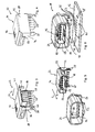
- the second connector 14 is connected to a line 16 connected. It is as complementary to the first connector 10 Connector designed and so with this plugged together to the cable 16 to the circuit substrate 12 and in particular on it to connect arranged conductor tracks.
- the first connector or the device holder 10 are shown in FIGS. 2 to 6 shown in more detail.
- the first connector 10 consists of three prefabricated, nested components, namely a first Contact element receptacle 18 with formed as a contact pins 20 Contact elements, one as a one-piece stamped and bent part of a metal sheet fabricated first shield 22 and a first housing 24th
- the trained as a plastic injection molded part first contact element receptacle 18 has an L-shape with a running in a direction of insertion S 1 first leg 26 with an asymmetrical cross section and a relative to this at an angle of 90 ° angled second leg 26 '.
- a first end face 28 of the first leg 26 is oriented orthogonal to the plug-in direction S 1 and a second end face 28 'of the second leg 26' orthogonal to the first end face 28.
- the contact element receptacle 18 includes in corresponding channels and grooves pressed several, in the example six, also L-shaped parallel contact pins 20, the conductor-side contacting ends 30 with respect to the insertion direction S 1 angled at an angle of about 90 ° from the second end face 28 'of second leg 26 'and the plug ends 32 extending parallel to the insertion direction S 1 extending from the first end face 28 of the first leg 26 protrude.
- a resilient metal sheet first shield 22 is shown in Fig. 2 in an already partially bent state, and has a sleeve portion 34 which corresponds in shape to the corresponding portion of the first contact element receptacle 18.
- a substantially U-shaped foot member 36 with arranged on opposite sides forked feet 38, which together with the sleeve portion 34 an orthogonal to the insertion direction S 1 oriented insertion opening 40 encloses U-shaped.
- the contact element receptacle 18 in the first shield 22 can be inserted (see Fig .. 3).
- the sleeve portion 34 and in particular its interior have transversely to the direction of insertion on a cross section corresponding to the cross section of the contact element receiving transversely to the insertion direction S 1 , so that the contact element receptacle 18 closely fitting to the inner wall of the sleeve portion 34 is inserted into this.
- two resilient snap hooks 46 are formed as securing elements, which are formed by a spring arm with a hook-shaped portion formed thereon by bending.
- the hook-shaped portions are bent in a V-shape with obliquely inclined to the plug-in direction S 1 legs.
- These securing elements are arranged symmetrically to each other on opposite sides of the sleeve portion 34, wherein the hook-shaped protruding portions each point into the interior of the sleeve portion 34.
- the securing elements 46 simultaneously serve for contacting a second shield of the second connector 14.
- the foot part 36 also corresponds in shape to the shape of the corresponding one Section of the first contact element receptacle 18, i. of second leg 26 ', wherein the forked feet 38 for mounting on the circuit carrier 12 are formed in corresponding holes 48.
- the wing 42 is dimensioned such that by bending the wing 42 along a bending line orthogonal to the plug-in direction S 1, the insertion opening 40 is essentially coverable or closable by the wing 42 (see Fig .. 4).
- the wing 42 and the side parts 44 thereto are formed so that in the bent state, the lower edge is approximately aligned with the lower edge of the foot part 36 and the leg 26 '.
- On the side parts 44 further bent guide rails 50 are formed, which extend in the bent state in Fig. 4 parallel to the insertion direction S 1 .
- the first housing 24 is integrally formed as an injection molded part of a dimensionally stable plastic sleeve-like with an asymmetric, the cross section of the first shield 18 corresponding cross-section transverse to the insertion direction S 1 . It has for attachment to the circuit substrate 12 has two retaining pin 52 and a substantially U-shaped wall portion 54 which is formed so that it receives the foot portion 36 of the shield substantially form-fitting manner, and when mounted on the circuit substrate 12 on this with his lower edge is seated.
- a circumferential receiving groove 56 to Recording a housing collar of the second connector 14 is formed. Furthermore, parallel to the plug-in direction Si, which are parallel to the Walls of the sleeve-like portion of the housing 24 extends, retaining grooves 58 for receiving the guide rails 50 on the side parts 44 of the Wing 42 of the first shield 22 is formed.
- the first contact element receptacle 18 in the first shield 22 is inserted.
- the wing 42 is oriented parallel to the plug-in direction S 1 in the assembled state.
- the part of the sleeve portion 34, which projects beyond the end face 28, now forms a collar 59 surrounding the plug-in ends 32, the edge of which protrudes beyond the plug-in ends 32 in the insertion direction S 1 .
- the wing 42 is bent over to the first contact element receptacle 18 until it is angled at an angle of about 90 ° relative to the plug-in direction S 1 at the edge of the foot portion 36 abuts (see Fig .. 4).
- the first contact element receptacle 18 is now secured against movements parallel to the plug-in direction S 1 by the bent wing 42 on the one hand and the wing section 42 opposite the wall portion of the foot part 36 on the other.
- the first contact element receptacle 18 including the plug-in ends 32 to the end faces of the legs 26 and 26 ' is substantially completely enclosed by the first shield 22.
- the unit thus formed is inserted into the first housing 24, wherein the guide rails 50 are inserted at the side parts 44 in the retaining grooves 58 in the first housing 24.
- These are designed such that, at least for assembly purposes, the unit of first contact element receptacle 18 and first shield 22 is connected to the housing 24 by means of a clamping fit.
- a bending of the wing 42 in a position parallel to the insertion direction S 1 is now blocked by the guide rails 50 held in the retaining grooves 58, so that the first contact element receptacle 18 is securely held in the first shield 22.
- the first housing 24 surrounds the sleeve portion 34 of the first shield 18 so that it is mechanically well protected.
- the unit thus formed can now be mounted on the circuit carrier 12 be, with the feet 38 in the holes 48, the retaining pin 52 in corresponding Fixing holes 60 and the contacting ends 30 in Contact holes 62 are introduced.
- the retaining pins 52 sit while in the press fit in the mounting holes 60.
- the feet 38 are used both as a mechanical support for the first shield 22 as well for contacting printed conductors on the circuit carrier 12.
- the so very easy to manufacture first connector 10 in the form of a device holder is then very firm even with very large insertion forces on the Circuit carrier 12 is held.
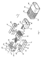
- the second connector 14 is shown in more detail in FIG. He has one second contact element receptacle 64, a second shield 66 with two Shielding parts 68 and 70, a locking element 72 with two resilient elements 74 and a housing 76 with a housing cap 78 and an actuating part 80.
- the second contact element receptacle 64 is likewise designed as a plastic injection-molded part and has a flat cuboidal basic shape.
- a plurality of, in the example, six channels arranged in a row parallel to one another, for receiving contact elements 82, are formed parallel to a plug-in direction S 2 of the second plug connector.
- the contact elements 82 have on the plug side contact sockets and on a conductor side means for abutting cables 84 of the line 16 and for establishing a crimp connection with the cables 84.
- the second shield 66 consists of the two designed as stamped and bent parts shielding parts 68 and 70, which can be put together in a direction transverse to the insertion direction S 2 .
- the two shield parts 68 and 70 are substantially U-shaped so that they enclose the second contact element receptacle 64 after mating and abut against this.
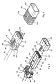
- the first shielding member 68 is for connection to the second Shielding part 70 has two pairs of first tongues 88 and second tongues 90, which are each lowered relative to the outer surfaces.
- the second shielding member 70 has, in an L-shaped outer portion 92, opposed flat recessed portions 94 protruding parallel to its surface beyond the L-shaped portion 92. Breakthroughs 96 are furthermore punched out in the recessed regions 94, which roughly correspond in shape to the shape of the first tongues 88. At the opposite side of the insertion direction S 2 side of the openings 96 each support elements 98 are bent approximately orthogonal to the level of the recessed areas 94. Furthermore, a sixteenbiegbare clamp 100 is formed for contacting a not shown in the figures shielding of the line 16 at the opposite end of the insertion direction S 2 end face.
- the second shielding member is also 70 except for the clamp 100 symmetrical to a parallel to the recessed Formed area 94 extending plane.
- the recessed portions 94 are opposite to the L-shaped portion 92 so far lowered that the locking projections 86 of the second contact element receptacle 64 in the frontal portion of the L-shaped portion 92nd are durable.
- the housing cap 78 is in two parts and consists of a top 102 and a Lower part 104 plugged together and has a corresponding from Cuff sections of the upper and lower part formed cuff 106 for receiving the line 16.
- the housing cap 78 is essentially pot-shaped, wherein the pot walls are shaped so that they are put together Shield 66 can receive partially and positively (see FIG. 9).
- each two fasteners 108 formed by means of which the actuating member 80 slidably on the Housing cap 78 is durable.
- the breadth of the shift is here through the length of slots 110 in the fasteners 108 certainly.
- support elements 112 formed in the form of the support elements 98th correspond to the second shielding part 70 and these in the assembled Support the condition of the second connector.
- the locking element 72 is also sleeve-shaped as a plastic injection molded part executed and corresponds in shape substantially the shape of the sleeve-shaped portion of the housing cap 78.
- On opposite Flat sides of the locking element 72 are stop elements 114 formed, which serve on the one hand, the resilient, in Shape of coil springs formed to hold elements 74 and the other than driving stroke to act.
- two optional sliding plates 116 are fastened in metal in the edge portion in the insertion direction S 2 .
- the actuating member 80 is also formed as an injection molded part made of plastic. It has the form of a sleeve which receives the locking element 72 and the housing cap 78 at least partially tight fitting.
- a front housing collar 118 in the direction of insertion S 2 has smooth walls and a cross-section such that it can be inserted in a form-fitting manner into the first housing 24 and in particular its receiving groove 56.
- a rear handle portion 120 seen in the direction of insertion S 2 symmetrical parallel to the insertion direction S 2 extending, opposite ends of the insertion direction S 2 open guide channels 122 are formed on opposite flat sides, in which the support members 98, the housing support members 112 and the stop members 114 are feasible.
- actuating part 80 to on the fasteners 108 complementary fasteners on so that the actuating member 80 slidably on the housing cap 78th held and managed.
- first Cable 84 struck against the contact elements 82 by crimping.
- the Contact elements 82 are then injection molded second contact element receptacle 64 is inserted and there in a known Way latched.
- the two shielding parts 68 and 70 transversely to the plug-in direction S2 via the second contact element receptacle 64, with the second tongues 90 under the L-shaped section 92 and edge portions of recessed areas 94 in the first Shielding 68 engage.
- the first tongues snap 88 in the apertures 96 and close them.
- the contact element holder 64 is now completely up to its front sides of the shield 66 enclosed because the apertures 96 through the first tongues 88 are covered.
- the contact element receptacle 64 is opposite the shield 66 is no longer displaceable, since the locking projections 86 engage in the acting as a blocking element L-shaped portion 92.
- the clamp 100 becomes the exposed shield of the conduit 16 bent and contacted with this (see Fig. 8).
- the exposed recessed areas 94 now form recesses 124 on opposite sides. At their end faces in the insertion direction S 2 , the recesses 124 define shoulders each having a securing projection 126 as securing elements complementary to the securing elements or snap hooks 46.
- the operating part 80 is on the resulting Unit pushed and locked with the housing cap 78, so that the second connector 14 shown in Fig. 1 is formed.
- the second connector with the actuating member 80 is inserted into the first housing 24, wherein the non-symmetrical shape of the inner cross section of the housing 24 and the corresponding outer cross section of the actuating part 80th or the housing collar 118 excluded accidental rotation is.
- the housing collar 118 is designed so that it is in the receiving groove 56 in the housing 24 substantially form-fitting manner is.
- the mating ends 32 of the contact pins 20 are inserted into the contact elements 82 in the second contact element receptacle 64, wherein at the same time, favored by mutually bent edges on the front side of the second shield 66, in Figs. 10 to 15 only incomplete and schematically shown snap hook 46 of the second shield 66 are resiliently bent apart and thus stretched. They abut against the end face of the locking element 72 and push the locking element 72, which surrounds the shield 66 and is guided in the guide channel 118 with the stop element 114, from a locking position in which it covers the recesses 124 and the securing projections 126 against the plug-in direction S 1 to the housing cap 78 to.
- the resilient elements 84 are supported on the support elements 98 of the second shield 66.
- the locking element 72 is the Securing projections 126 and the recess 124 at least partially free, so that the snap hooks 46 behind the securing projections 126 can snap into the recesses 124 in a backup position (see Fig. 11). The locking element 72 then has the unlocking position reached.
- the snap hooks 46 after snapping into the recesses 124, no longer block the locking member 72 so that it is urged by the resilient members 74 that are urged by the movement of the locking member 72 relative to the second shield 66
- Snap hook 46 is moved away in its locking position, in which now the wells 124 with the securing projections 126 and the snap hooks 46 are covered.
- a movement of the snap hook 46 in a direction orthogonal to the plug-in direction S 1 or S 2 that is, beyond the securing projections 126 away, no longer possible.
- the first and second connectors 10 and 14 are now secured in the mated position, since the snap hooks 46 engage behind the securing projections 126 and thus prevent a disengagement of the two connectors parallel to the direction of insertion.
- the actuating member 80 is moved by an opening movement opposite to the insertion direction S 2 on the housing cap 78 to an open position, wherein the run in the guide channels 122 stop elements 114 acting as driving stops 128 acting in the direction of insertion S 2 end walls 130 of the guide channels 122nd be taken as complementary attacks.
- the locking element 72 is moved from the locking position into the unlocking position.
- a predetermined by the resilient elements 74 and their spring constant force is necessary so that accidental movement of the actuating member 80 by specifying appropriate forces or spring constants of the resilient elements 74 can be largely excluded.
- the length or locking position of the locking element 72 is selected so that the actuating member 80 only over a predetermined Distance, in the example about 6 mm, must be moved until the Unlocking is achieved. This excludes, on the one hand, that in a short, random movement of the operating part 80 already a release can take place.
- the minimum unlocking force can be easily adjusted, which is necessary to effect unlocking.
- the snap hooks 46 of the first Shield 22 by applying a corresponding force over the Retaining projections 126 pulled and spread apart, including the corresponding hook-shaped portions substantially V-shaped are bent so that the securing projections 126 on the corresponding Legs of the hook-shaped sections are guided.
- the Snap hooks 46 do not hinder the further pulling apart more, so that the connectors can be completely separated.
Landscapes
- Details Of Connecting Devices For Male And Female Coupling (AREA)
- Connector Housings Or Holding Contact Members (AREA)
- Earth Drilling (AREA)
- Piezo-Electric Or Mechanical Vibrators, Or Delay Or Filter Circuits (AREA)
- Quick-Acting Or Multi-Walled Pipe Joints (AREA)
Abstract
Description
Die vorliegende Erfindung betrifft einen Steckverbinder zum Zusammenstecken mit einem komplementären Steckverbinder, insbesondere zur Verwendung in einem Kraftfahrzeug.The present invention relates to a connector for mating with a complementary connector, in particular for Use in a motor vehicle.
Steckverbinder werden dazu benutzt, auf einfache Weise Leitungen mit einer anderen Leitung oder einem Schaltungsträger mit einer elektrischen Schaltung elektrisch und auch mechanisch zu verbinden. Steckverbinder finden daher insbesondere auch Anwendung im Kraftfahrzeugbau. In diesem Verwendungsbereich müssen solche Steckverbinder zum einen sehr kostengünstig herstellbar sein und zum anderen auch unter ungünstigen Einsatzbedingungen, insbesondere bei Vibrationen und/oder Stößen, eine stabile Verbindung erlauben.Connectors are used to easily lines with another line or a circuit carrier with an electrical Circuit electrically and mechanically connect. Connectors therefore find particular application in motor vehicle construction. In This area of use must such connectors on the one hand be very inexpensive to produce and on the other under unfavorable Operating conditions, in particular with vibrations and / or shocks, allow a stable connection.
In Kraftfahrzeugen werden zur Übertragung von Steuersignalen oder Daten neben analogen zunehmend auch digitale Datenverbindungen eingesetzt. Um Störungen bei der Datenübertragung durch andere elektrische oder elektronische Einrichtungen, insbesondere durch von diesen abgegebene elektromagnetische Strahlung, zu reduzieren, ist es wünschenswert, für die Datenübertragung abgeschirmte elektrische Verbindungen auch im Kraftfahrzeugbereich einzusetzen.In motor vehicles are used for the transmission of control signals or Data in addition to analog increasingly digital data connections used. To disturbances in data transmission by other electrical or electronic devices, in particular by these emitted electromagnetic radiation, it is desirable to shielded electrical connections for data transmission also in the automotive field use.
Ein Steckverbinder mit den Merkmalen des Oberbegriffes des Anspruches 1 ist aus US-A-4 900 262 bekannt.A connector having the features of the preamble of the claim 1 is known from US-A-4 900 262.
Der vorliegenden Erfindung liegt daher die Aufgabe zugrunde, einen einfachen Steckverbinder bereitzustellen, mittels dessen einfach störungsarme Verbindungen zu einem Schaltungsträger oder abgeschirmten Leitungen herstellbar sind.The present invention is therefore based on the object, a simple To provide connectors by means of which simply low-interference Connections to a circuit carrier or shielded cables can be produced.
Die Aufgabe wird gelöst durch einen Steckverbinder mit den Merkmalen des Anspruchs 1.The object is achieved by a connector with the features of claim 1.
Der erfindungsgemäße Steckverbinder zum Zusammenstecken mit einem komplementären Steckverbinder in einer Steckrichtung, insbesondere zur Verwendung in einem Kraftfahrzeug, weist eine Kontaktelementaufnahme zur Aufnahme eines Kontaktelements, vorzugsweise von wenigstens zwei Kontaktelementen, eine die Kontaktelementaufnahme wenigstens teilweise umgebende Abschirmung und ein die Kontaktelementaufnahme und die Abschirmung wenigstens teilweise aufnehmendes Gehäuse auf.The connector according to the invention for mating with a complementary connector in a plugging direction, in particular for Use in a motor vehicle, has a contact element receptacle for receiving a contact element, preferably at least two Contact elements, a contact element receiving at least partially surrounding shield and a contact element receptacle and the Shielding at least partially accommodating housing.
Eine Kontaktelementaufnahme zur Aufnahme von Kontaktelementen ist vorgesehen. Die Kontaktelementaufnahme, die vorzugsweise als Kunststoffspritzgussteil ausgebildet ist, kann dazu entsprechende Aufnahmekanäle aufweisen. Die Kontaktelemente können in die Kontaktelementaufnahme eingeschoben, eingepresst oder auch eingespritzt sein.A contact element receptacle for receiving contact elements is intended. The contact element receiving, preferably as a plastic injection molded part is formed, can corresponding recording channels exhibit. The contact elements can be in the contact element receptacle pushed in, pressed or injected.
Vorzugsweise ist die Kontaktelementaufnahme zur Aufnahme von wenigstens zwei, besonders bevorzugt mehr als zwei Kontaktelementen ausgebildet. Ein solcher Steckverbinder eignet sich dann insbesondere zur Verbindung von Leitungen eines Bussystems in einem Kraftfahrzeug, die häufig mehrere Adern aufweisen.Preferably, the contact element receptacle for receiving at least two, more preferably formed more than two contact elements. Such a connector is then particularly suitable for connection of lines of a bus system in a motor vehicle, often have multiple wires.
Grundsätzlich können beliebige Kontaktelemente, beispielsweise Kontaktstifte, -zungen oder -messer oder Kontaktbuchsen, verwendet werden. Die Kontaktelemente sind an Leiter anschließbar, unter denen im Rahmen der Erfindung nicht nur Adern von Kabeln verstanden werden, sondern auch Leiterbahnen auf Schaltungsträgern. In principle, any contact elements, such as pins, tongues or blades or contact sockets. The Contact elements are connectable to conductors, among which under the Invention not only wires of cables are understood, but also Tracks on circuit boards.
Die aus einem elektrisch leitenden Material, vorzugsweise einem Metall gefertigte Abschirmung dient zur Abschirmung von Kontaktelementen in der Kontaktelementaufnahme gegen elektrische und elektromagnetische Felder. Sie kann dazu insbesondere eine Kontaktierungseinrichtung aufweisen, an die ein Leiter mit einem Bezugspotential, beispielsweise Masse, anschließbar ist. Die Abschirmung nimmt vorzugsweise die Kontaktelementaufnahme auf.The of an electrically conductive material, preferably a metal manufactured shield serves to shield contact elements in the contact element recording against electrical and electromagnetic Fields. In particular, it can have a contacting device, to which a conductor with a reference potential, for example ground, is connectable. The shield preferably takes the contact element receptacle on.
Weiterhin können die Abschirmungen des Steckverbinders und des komplementären Steckverbinders zweckmäßig so ausgebildet sein, dass beim Zusammenstecken der Steckverbinder ein elektrischer Kontakt zwischen den Abschirmungen hergestellt wird.Furthermore, the shields of the connector and the complementary Connector be suitably designed so that when Plug the connectors into electrical contact between the shields is made.
Die Kontaktelementaufnahme und die diese wenigstens teilweise umgebende Abschirmung werden wenigstens teilweise von dem Gehäuse umgeben, das diese vor äußeren Einflüssen schützt und insbesondere auch zur mechanischen Verbindung mit einem komplementären Steckverbinder bzw. dessen Gehäuse ausgebildet sein kann. Insbesondere können die Gehäuse des Steckverbinders und/oder des komplementären Steckverbinders Führungen aufweisen, mittels derer die Steckverbinder beim Zusammenstecken an- bzw. ineinander führbar sind.The contact element receiving and at least partially surrounding this Shield are at least partially surrounded by the housing, this protects against external influences and in particular for mechanical connection with a complementary connector or whose housing may be formed. In particular, the housing can the connector and / or the complementary connector Have guides by means of which the connector when mating on or in one another are feasible.
Um das Risiko, dass sich eine hergestellte Steckverbindung beispielsweise durch Vibrationen und/oder Stöße zufällig löst, zu reduzieren, weist die Abschirmung wenigstens ein Sicherungselement, vorzugsweise ein Schnapp- oder Rastelement, auf, das beim Zusammenstecken des Steckverbinders mit einem entsprechenden komplementären Steckverbinder relativ zu einem komplementären Sicherungselement des komplementären Steckverbinders, vorzugsweise einem komplementären Schnapp- oder Rastelement, in eine Sicherungslage relativ zu dem komplementären Sicherungselement bewegbar ist und mittels dessen in der Sicherungslage durch Zusammenwirken mit dem komplementären Sicherungselement eine Relativbewegung der Steckverbinder aus der zusammengesteckten Lage heraus begrenzbar ist. Der komplementäre Steckverbinder kann insbesondere als geeignet ausgebildeter erfindungsgemäßer Steckverbinder, insbesondere nach einem der Ansprüche 1 bis 8, mit einem entsprechenden komplementären Sicherungselement ausgebildet sein. Eines der Sicherungselemente ist wenigstens teilweise, vorzugsweise in einer von der Steckrichtung abweichenden Richtung, bewegbar. Der Steckverbinder und der komplementäre Steckverbinder sind daher zumindest in einem vorgegebenen Bereich von Lagen in einem zusammengesteckten Zustand, in dem die Kontaktelemente und die komplementären Kontaktelemente noch in Kontakt miteinander sind, sicherbar, das heißt nur unter Überwindung von durch die Sicherungselemente bestimmten Kräften auseinander bewegbar. Die Sicherungselemente können insbesondere so ausgebildet sein, dass eine Relativbewegung der Steckverbinder aus der zusammengesteckten Lage blockiert ist. Die Sicherungselemente können weiterhin in der Sicherungslage einen Kontakt zwischen den Abschirmungen der zusammengesteckten Steckverbinder bereitstellen, wenn das komplementäre Sicherungselement ebenfalls an einer Abschirmung des komplementären Steckverbinders ausgebildet ist. Die Verwendung von Schnapp- oder Rastelementen hat den Vorteil, dass diese bei Erreichen der Sicherungslage selbsttätig unter Bildung einer Schnapp- oder Rastverbindung ineinander einschnappen bzw. -rasten können, so dass die Sicherung automatisch erfolgen kann.For example, the risk of having a manufactured connector due to vibrations and / or shocks accidentally triggers, reduce, rejects Shielding at least one securing element, preferably one Snap or locking element, on, when plugging the connector with a corresponding complementary connector relative to a complementary securing element of the complementary Connector, preferably a complementary snap or Locking element, in a securing position relative to the complementary Fuse element is movable and by means of which in the backup position by cooperation with the complementary securing element a relative movement of the connector from the mated Location is limited. The complementary connector can in particular as a suitably designed connector according to the invention, in particular according to one of claims 1 to 8, with a corresponding be formed complementary security element. One of the Securing elements is at least partially, preferably in one of the Plug direction deviating direction, movable. The connector and the complementary connector are therefore at least in a predetermined Range of layers in a mated state, in the contact elements and the complementary contact elements still are in contact with each other, securable, that is, only by overcoming apart from certain forces determined by the securing elements. The securing elements can in particular be designed in this way be that a relative movement of the connector from the mated Location is blocked. The fuse elements can continue in the backup position a contact between the shields of the assembled Provide connector if the complementary Securing element also on a shield of the complementary Connector is formed. The use of snap or Locking elements has the advantage that these when reaching the backup position automatically to form a snap or locking connection with each other Snap or snap, allowing the backup automatically can be done.
Weiterer Gegenstand der Erfindung ist ein Steckverbindersystem mit einem ersten erfindungsgemäßen Steckverbinder und einem erfindungsgemäßen, mit dem ersten Steckverbinder zusammensteckbaren, zu diesem komplementären zweiten Steckverbinder. Der komplementäre zweite Steckverbinder kann hierzu insbesondere in einer entsprechend ausgebildeten Kontaktelementaufnahme angeordnete, entsprechende, zu den Kontaktelementen des ersten Steckverbinders komplementäre zweite Kontaktelemente sowie ein Gehäuse, das ein Zusammenstecken mit dem Gehäuse des ersten Steckverbinders erlaubt, aufweisen.Another object of the invention is a connector system with a first connector according to the invention and an inventive, connectable to the first connector, to this complementary second connector. The complementary second Connector can this purpose, in particular in a trained accordingly Contact element receiving arranged, corresponding to the Contact elements of the first connector complementary second Contact elements as well as a housing that mates with the Housing of the first connector allowed to have.
Die erfindungsgemäßen Steckverbinder erlauben eine einfach Verbindung einer abgeschirmten Leitung mit einer anderen, insbesondere ebenfalls abgeschirmten, Leitung oder einem Schaltungsträger, wobei der Kontaktierungsbereich wenigstens teilweise abgeschirmt und damit störungsarm ist.The connectors according to the invention allow a simple connection a shielded cable with another, in particular also shielded, line or a circuit carrier, wherein the contacting region at least partially shielded and thus trouble-free is.
Weiterbildungen und bevorzugte Ausführungsformen der Erfindung sind in der Beschreibung, den Ansprüchen und den Zeichnungen beschrieben.Further developments and preferred embodiments of the invention are in the description, claims and drawings.
Das Gehäuse kann grundsätzlich beliebig aufgebaut sein, jedoch ist eine Ausführungsform bevorzugt, bei der das Gehäuse aus wenigstens zwei Gehäuseteilen zusammengesetzt, insbesondere zusammengesteckt und/oder -geschoben, ist. Die, vorzugsweise als Kunststoff-Spritzgussteile ausgebildeten, Gehäuseteile können dazu Befestigungselemente aufweisen, durch die sie miteinander gegebenenfalls beweglich verbunden sind. Insbesondere bei einer Ausbildung zum Zusammenstecken und/oder -schieben ist eine besonders einfache maschinelle Verbindung der Gehäuseteile möglich. Der Steckverbinder ist dann durch Zusammenfügen der Kontaktelementaufnahme, der Abschirmung und des Gehäuses einfach herstellbar. Insbesondere kann ein Anspritzen des Gehäuses an eine Leitung vermieden werden, wenn diese durch Zusammenstecken der Gehäuseteile umschlossen werden kann. Die Gehäuseteile können hierzu vorzugsweise in Randbereichen entsprechende Einbuchtungen aufweisen, die erst nach Zusammenfügen der Gehäuseteile eine Öffnung zur Aufnahme der Leitung bilden. Die Einbuchtungen können vorzugsweise Abschnitte einer Manschette aufweisen, die nach dem Zusammenfügen des Gehäuses eine Leitung umgibt. Die Leitung kann dann bei dem Zusammenfügen der Gehäuseteile in das Gehäuse einbaut werden. Dies kann insbesondere dann vorteilhaft sein, wenn die Kontaktelemente mit der Leitung vor Zusammenbau des Steckverbinders verbunden werden sollen, um eine einfache Handhabung beim Zusammenbau zu ermöglichen. Die Herstellung eines solchen Steckverbinders wie auch dessen Verbindung mit einer Leitung ist dann besonders kostengünstig.The housing can be constructed basically arbitrary, but is a Embodiment preferred, wherein the housing of at least two Assembled housing parts, in particular put together and / or pushed. The, preferably as plastic injection molded parts trained housing parts can have fastening elements for this purpose, by which they are optionally connected movably. In particular, in a training for mating and / or pushing is a particularly simple mechanical connection of the housing parts possible. The connector is then assembled by joining the Contact element reception, shielding and housing easy produced. In particular, a molding of the housing to a Line be avoided if this by plugging the Housing parts can be enclosed. The housing parts can do this preferably have corresponding indentations in edge regions, the only after joining the housing parts an opening for receiving form the line. The indentations may preferably Have portions of a cuff after joining of the housing surrounds a conduit. The line can then join the housing parts are installed in the housing. This can be particularly advantageous if the contact elements with the line are connected before assembling the connector to allow easy handling during assembly. The production of such a connector as well as Connection with a line is then particularly cost-effective.
Alternativ ist es bevorzugt, dass das Gehäuse einstückig ausgebildet ist, und einen hülsenförmigen Abschnitt umfasst, in den die Abschirmung mit der Kontaktelementaufnahme eingeschoben ist. Die Abschirmung mit der Kontaktelementaufnahme ist dabei durch eine Relativbewegung zwischen dem Gehäuse und der Abschirmung mit der Kontaktelementaufnahme in den hülsenförmigen Abschnitt eingeschoben, so dass auch das Gehäuse über die Abschirmung geschoben sein kann. Ein solches Gehäuse ist besonders einfach aufgebaut und stabil. Weiterhin ist es einfach durch Kunststoffspritzguss herstellbar. Besonders bevorzugt weist das Gehäuse dann eine Klappe zum wenigstens teilweisen Verschließen einer Öffnung auf, durch die die Abschirmung mit der Kontaktelementaufnahme in das Gehäuse einschiebbar ist. Die Klappe kann gegebenenfalls in einem Randbereich eine Einbuchtung aufweisen, durch die eine Leitung führbar ist.Alternatively, it is preferred that the housing is formed in one piece, and a sleeve-shaped portion, in which the shield with the contact element receptacle is inserted. The shield with the Contact element reception is characterized by a relative movement between the housing and the shield with the contact element receiving in pushed the sleeve-shaped portion, so that the housing can be pushed over the shield. Such a housing is very simple and stable. Furthermore it is easy through Plastic injection molding produced. Particularly preferably, the housing then a flap for at least partially closing an opening on, through which the shield with the contact element receiving in the Housing is inserted. The flap can optionally be in one Edge region have a recess through which a conduit feasible is.
Zur besonders einfachen Herstellung der Abschirmung ist es bevorzugt, dass diese aus einem oder mehreren Stanz-Biegeteilen gebildet ist. Die Abschirmung ist so besonders einfach und auch voll- bzw. großflächig herstellbar.For particularly simple production of the shield, it is preferred that this is formed from one or more stamped and bent parts. The Shielding is so very easy and also full or large area produced.
Um eine möglichst gute Abschirmung zu erhalten, ist es bevorzugt, dass die Abschirmung die Kontaktelementaufnahme möglichst vollständig, insbesondere im Wesentlichen bis auf die Stirnseiten der Kontaktelementaufnahme, an oder in denen Teile von Kontaktelementen angeordnet sind, derselben umschließt. Im Wesentlichen bedeutet dabei insbesondere, dass an Nähten oder Ecken kleine herstellungsbedingte Lücken oder Löcher auftreten können, vorzugsweise jedoch nicht in Flächen. Besonders bevorzugt umgibt die Abschirmung auch auf der Steckseite der Kontaktelementaufnahme aus dieser herausragende Enden von in der Kontaktelementaufnahme angeordneten Kontaktelementen.In order to obtain the best possible shielding, it is preferred that the shield as completely as possible, in particular substantially to the end faces of the contact element receptacle, on or in which parts of contact elements are arranged, encloses same. In essence, this means in particular that at seams or corners small manufacturing gaps or holes may occur, but preferably not in areas. Especially preferred surrounds the shield also on the mating side of the contact element receptacle from this protruding ends of in the contact element receptacle arranged contact elements.
Bei einer Ausführungsform ist es bevorzugt, dass die Abschirmung wenigstens zwei quer zu der Steckrichtung schiebbare Abschirmungsteile aufweist, die vorzugsweise als Stanz-Biegeteile ausgebildet sind. Besonders bevorzugt weist die Abschirmung dabei nur zwei Abschirmungsteile auf. Vorzugsweise werden die Abschirmungsteile über die Kontaktelementaufnahme geschoben. Die Abschirmungsteile können dabei noch komplementäre Befestigungselemente aufweisen, mittels derer sie miteinander verbindbar sind. Auf diese Weise kann eine Abschirmung sehr einfach auch für Kontaktelementaufnahmen bereitgestellt werden, die ein einfaches Aufschieben einer Abschirmung in Steckrichtung nicht oder nur mit zusätzlichen Arbeitsschritten erlauben.In one embodiment, it is preferred that the shield be at least two sliding transversely to the direction of insertion shielding parts has, which are preferably formed as stamped and bent parts. Especially Preferably, the shield has only two shielding parts on. Preferably, the shielding parts are via the contact element receptacle pushed. The shielding parts can still Have complementary fasteners by means of which they together are connectable. In this way, a shield can be very simply be provided for contact element receptacles that a simply pushing a shield in the direction of insertion not or only allow with additional steps.
Dabei ist es besonders bevorzugt, dass die Kontaktelementaufnahme und die Abschirmung quer zu der Steckrichtung verlaufende, zusammenwirkende Sperrelemente aufweisen, die eine Relativbewegung zwischen der Kontaktelementaufnahme und der Abschirmung in und/oder entgegen der Steckrichtung blockieren. Bei diesen Sperrelementen kann es sich insbesondere um eine Nut und eine entsprechende Leiste oder gegeneinander stoßende Vorsprünge handeln. Auf diese Weise kann bei einfacher Herstellbarkeit der Abschirmung sicher eine Relativbewegung zwischen der Abschirmung und der Kontaktelementaufnahme auch beim Auftreten größerer Steckkräfte auf die Kontaktelemente und damit die Kontaktelementaufnahme verhindert werden. It is particularly preferred that the contact element receiving and the shield extending transversely to the direction of insertion, cooperating Have blocking elements which have a relative movement between the Contact element receptacle and the shield in and / or against the Block plug-in direction. In particular, these locking elements can around a groove and a corresponding bar or against each other acting protrusions. In this way, with ease of manufacture the shield sure a relative movement between the Shielding and the contact element recording even when occurring larger insertion forces on the contact elements and thus the contact element recording be prevented.
Alternativ ist es bevorzugt, dass die Abschirmung einstückig als Stanz-Biegeteil ausgebildet ist. Solche Abschirmungen zeichnen sich nicht nur durch eine besonders einfache und kostengünstige Herstellung aus, sondern erlauben auch eine einfache Herstellung des Steckverbinders, da nur ein Teil zu handhaben ist.Alternatively, it is preferred that the shield in one piece as a stamped and bent part is trained. Such shields are not only stand out by a particularly simple and inexpensive production, but also allow easy production of the connector, as only a part is to handle.
Weiterhin ist es bevorzugt, dass die Abschirmung einen gegenüber der Steckrichtung abgewinkelten, umgebogenen Flügel aufweist, der wenigstens teilweise eine Einschuböffnung in der Abschirmung verschließt, durch die die Kontaktelementaufnahme in die Abschirmung einschiebbar ist. Hierdurch wird zum einen eine gute Abschirmung auch einer solchen Einschuböffnung erreicht. Zum anderen wird eine Relativbewegung zwischen Kontaktelementaufnahme und Abschirmung entgegen der Steckrichtung verhindert, da diese durch den umgebogenen Flügel blockiert wird. Die Kontaktelementaufnahme kann so nicht durch Steckkräfte beim Zusammenstecken mit einem anderen Steckverbinder wieder aus der Abschirmung geschoben werden. Solche Abschirmungen werden vorzugsweise mit Kontaktelementaufnahmen verwendet, die zur Aufnahme von Kontaktelementen ausgebildet sind, deren leiterseitigen Enden gegenüber der Steckrichtung abgewinkelt sind. Beispielsweise können diese, wie auch die Kontaktelementaufnahme im Wesentlichen L-förmig ausgebildet sein. Der umgebogenen Flügel kann dann insbesondere in einem Winkel von etwa 90° gegenüber der Steckrichtung abgewinkelt sein. Eine solche Abschirmung kann vor einem Abbiegen des Flügels aus einer vorzugsweise parallel zu der Steckrichtung ausgerichteten Lage einfach auf die Kontaktelementaufnahme aufgeschoben bzw. die Kontaktelementaufnahme in die Abschirmung eingeschoben werden, woraufhin der Flügel auf die Kontaktelementaufnahme umgebogen wird. Auf diese Weise ergibt sich bei sehr einfacher Herstellbarkeit eine gute Abschirmung auch bei abgewinkelten Kontaktelementen. Ein Flügel ist entsprechend auch für Kontaktelementaufnahmen verwendbar, die lineare Kontaktelemente aufnehmen und kann insbesondere eine Öffnung oder vorzugsweise eine Einbuchtung in dessen Rand aufweisen, durch die Kabel zu Kontaktelementen in der Kontaktelementaufnahme führbar sind. Grundsätzlich können auch mehrere Flügel zum Verschließen der Einschuböffnung verwendet werden.Furthermore, it is preferred that the shield has a relation to the Plug-in direction angled, bent wing having, at least partially closes an insertion opening in the shield, by the contact element recording in the shield inserted is. As a result, on the one hand a good shielding of such a Insertion opening reached. On the other hand, a relative movement between Contact element receptacle and shielding against the plugging direction prevented, as this blocked by the bent wing becomes. The contact element receptacle can not be so by plug forces Mating with another connector back out of the Shielding be pushed. Such shields are preferably used with contact element receptacles for receiving Contact elements are formed, the conductor-side ends opposite the plug-in direction are angled. For example, these, like also formed the contact element receiving substantially L-shaped be. The bent wing can then in particular at an angle be angled from about 90 ° relative to the direction of insertion. Such Shielding may occur before a turn of the wing from a preferably aligned parallel to the direction of insertion simply on the contact element receiving deferred or the contact element receiving in the shield are pushed in, whereupon the wing is on the Contact element holder is bent over. This results in very easy to produce a good shielding even with angled Contact elements. A wing is accordingly also for contact element recordings usable, which receive linear contact elements and may in particular an opening or preferably a recess in the edge, through the cable to contact elements in the Contact element holder are feasible. Basically, too several wings are used to close the insertion opening.
Dabei ist es besonders bevorzugt, dass an dem Flügel Halteelemente, die vorzugsweise im umgebogenen Zustand in Steckrichtung verlaufen, und in dem Gehäuse entsprechende komplementäre Halteelemente ausgebildet sind, mittels derer der umgebogene Flügel in einer zu der Steckrichtung geneigten Richtung relativ zu dem Gehäuse befestigbar ist. Zweckmäßig sind die Halteelemente und die komplementären Halteelemente so ausgebildet, dass die Abschirmung mit dem umgebogenen Flügel in das Gehäuse ein- bzw. das Gehäuse auf die Abschirmung mit dem umgebogenen Flügel aufschiebbar sind. Als Halteelemente können insbesondere parallel zu Steckrichtung verlaufende Nuten oder Schlitze in Verbindung mit entsprechenden Vorsprüngen, Leisten oder Federn verwendet werden. Auf diese Weise kann der Flügel einfach in das Gehäuse eingeschoben werden, wobei gleichzeitig ein späteres Umbiegen des Flügels blockiert wird. Der umgebogene Flügel kann dann insbesondere über die Kontaktelementaufnahme auf den Flügel ausgeübte Steckkräfte aufnehmen und auf das Gehäuse übertragen.It is particularly preferred that on the wing holding elements, the preferably in the bent state in the insertion direction, and formed in the housing corresponding complementary holding elements are, by means of which the bent wing in one to the direction of insertion inclined direction relative to the housing is fastened. expedient the retaining elements and the complementary retaining elements are designed that the shield with the bent wing in the housing one or the housing on the shield with the bent Wings are pushed on. As holding elements can in particular parallel to slot direction extending grooves or slots in conjunction with corresponding projections, strips or springs are used. On this way, the wing can simply be inserted into the housing, while blocking a later bending of the wing. Of the bent wing can then in particular via the contact element receptacle Take on the wing forces applied to the wing and on the Housing transferred.
Weiterhin ist es besonders bevorzugt, dass der Steckverbinder als Geräteaufnahme ausgebildet ist, wobei vorzugsweise auf gegenüberliegenden Seiten der Abschirmung Kontakte zur Verbindung mit einem Schaltungsträger ausgebildet sind. Die Kontakte der Abschirmung dienen dabei vorzugsweise zur mechanischen Verbindung mit dem Schaltungsträger und gleichzeitig zur elektrischen Verbindung mit Leiterbahnen auf dem Schaltungsträger. Weiterhin kann das Gehäuse zweckmäßigerweise zusätzliche Befestigungselemente, beispielsweise Zapfen aufweisen, mittels dessen es mit dem Schaltungsträger verbindbar ist, so dass es beispielsweise beim Zusammenstecken mit einem komplementären Steckverbinder auftretende Kräfte gut auf den Schaltungsträger übertragen kann. Die Kontaktelementaufnahme wie auch die Kontaktelemente können dabei vorzugsweise L-förmig ausgebildet sein, so dass die Steckrichtung parallel zu einem Schaltungsträger verlaufen kann, auf dem die Geräteaufnahme dann gehalten ist.Furthermore, it is particularly preferred that the connector as a device receptacle is formed, preferably on opposite Sides of the shield contacts for connection to a circuit carrier are formed. The contacts of the shield are used preferably for mechanical connection to the circuit carrier and at the same time for electrical connection to tracks on the Circuit carriers. Furthermore, the housing may expediently additional Attachment elements, for example, have pins by means of of which it is connectable to the circuit carrier, so that it for example when mating with a complementary connector occurring forces can be transferred well to the circuit carrier. The Contact element recording as well as the contact elements can thereby preferably be L-shaped, so that the plugging direction parallel can run to a circuit board on which the device receptacle then held.
Um eine besonders stabile Sicherung der Steckverbindung zwischen dem Steckverbinder und einem geeigneten komplementären Steckverbinder ermöglichen zu können, ist es bevorzugt, dass die Abschirmung zwei, vorzugsweise an gegenüberliegenden Seiten der Abschirmung ausgebildete, Sicherungselemente aufweist. Diese können jeweils gleich oder verschieden ausgebildet sein. Insbesondere bei Anordnung an gegenüberliegenden Seiten der Abschirmung können auftretende Kräfte besser verteilt werden. Darüber hinaus ergibt sich eine zusätzliche Sicherheit durch die erzielte Redundanz.To a particularly stable securing the connector between the Connector and a suitable complementary connector it is preferred that the shielding be two, preferably formed on opposite sides of the shield, Has safety elements. These can each be the same or different be educated. In particular, when arranged on opposite Sides of the shield can better distribute occurring forces become. In addition, there is additional security through the achieved redundancy.
Bei einer Ausführungsform des erfindungsgemäßen Steckverbinders ist es bevorzugt, dass das Sicherungselement einen federnden Schnapp- oder Rasthaken aufweist, der vorzugsweise in einem durch die Abschirmung gebildeten Kragen ausgebildet ist. Der federnde Schnapp- oder Rasthaken kann insbesondere durch einen Federarm mit einem an dessen freiem Ende angeordneten Schnapp- bzw. Rastvorsprung gebildet sein. Die Abschirmung ist dann vorzugsweise aus einem entsprechend elastischen Blech gefertigt. Ist der Schnapp- oder Rasthaken in einem durch die Abschirmung gebildeten Kragen ausgebildet, umgibt der Kragen vorzugsweise aus der Kontaktelementaufnahme herausragende Kontaktelemente, so dass diese vor und beim Zusammenstecken mechanisch geschützt und nach dem Zusammenstecken gut elektromagnetisch abgeschirmt sind. In one embodiment of the connector according to the invention it is preferred that the securing element is a resilient snap or Has latching hook, preferably in a through the shield formed collar is formed. The resilient snap or catch hook can in particular by a spring arm with a free at the Be formed end arranged snap or locking projection. The shield is then preferably made of a corresponding elastic Sheet metal made. Is the snap or catch hook in one by the Shield formed formed collar, the collar preferably surrounds From the contact element receiving outstanding contact elements, so that these are mechanically protected before and during mating and are well electromagnetically shielded after mating.
Weiterhin ist es bevorzugt, dass das Sicherungselement einen Sicherungsvorsprung aufweist, hinter den in der Sicherungslage ein Schnapp- oder Rasthaken eines mit dem Steckverbinder zusammengesteckten komplementären Steckverbinders greift. Der komplementäre Steckverbinder kann erfindungsgemäß und insbesondere gemäß der in dem vorhergehenden Absatz geschilderten Ausführungsform und/oder Anspruch 10 ausgebildet sein. Ein solches Sicherungselement bzw. Schnapp- oder Rastelement ist daher ein zu einem als Schnapp- oder Rasthaken ausgebildeten Sicherungselement komplementär. Der Sicherungsvorsprung kann dabei insbesondere durch eine Schulter einer Ausnehmung oder Vertiefung in der Abschirmung des Steckverbinders gebildet sein.Furthermore, it is preferred that the securing element has a securing projection has behind the in the backup position a snap or Latch hook of a mated with the connector complementary Connector engages. The complementary connector can according to the invention and in particular according to the preceding one Paragraph-described embodiment and / or claim 10 is formed be. Such a securing element or snap or locking element is therefore a fuse element designed as a snap-in or snap-in hook complementary. The securing projection can in particular through a shoulder of a recess or depression in the Shielding of the connector to be formed.
Insbesondere bei der Verwendung von Schnapp- oder Rastelementen als Sicherungselementen ist es nicht völlig ausgeschlossen, dass sich bei entsprechend starken Stößen oder Vibrationen die Sicherungselemente relativ zueinander aus der Sicherungslage herausbewegen und so in der Folge ein Lösen der Steckverbindung nicht blockiert wird. Es ist daher bevorzugt, dass ein relativ zu der Kontaktelementaufnahme zwischen einer Entriegelungslage und einer Verriegelungslage bewegbares Verriegelungselement vorgesehen ist, wobei in der Entriegelungslage des Verriegelungselements die Sicherungselemente des Steckverbinders und des komplementären Steckverbinders in die Sicherungslage und/oder aus dieser heraus bewegbar sind und das Verriegelungselement in der Verriegelungslage die Sicherungselemente ein ihrer Sicherungslage gegen eine Bewegung aus der Sicherungslage verriegelt. Der komplementäre Steckverbinder kann dabei erfindungsgemäß und insbesondere entsprechend einer oder mehrerer der zuvor geschilderten Ausführungsformen und/oder einem der Ansprüche 1 bis 11 ausgebildet sein. Especially when using snap or locking elements as Fuse elements, it is not completely excluded that at correspondingly strong shocks or vibrations, the security elements move out of the backup position relative to each other and so in the Result a release of the connector is not blocked. It is therefore preferred that a relative to the contact element receiving between an unlocking position and a locking position movable locking element is provided, wherein in the unlocking position of the locking element the fuse elements of the connector and the complementary connector in the backup position and / or off this are movable out and the locking element in the locking position the fuse elements one of their backup position against a Motion locked from the backup position. The complementary connector can according to the invention and in particular accordingly one or more of the previously described embodiments and / or be formed of one of claims 1 to 11.
Um eine besonders kompakte Steckverbindung zu ermöglichen, ist es bevorzugt, dass das Verriegelungselement parallel zu der Steckrichtung relativ zu der Abschirmung verschiebbar ist und vorzugsweise die Abschirmung wenigstens teilweise hülsenartig umgibt. Eine Ausbildung als Hülse ist insbesondere dann vorteilhaft, wenn zwei an gegenüberliegenden Seiten der Abschirmung ausgebildete Sicherungselemente vorgesehen sind, da dann mit nur einem Verriegelungselement beide Sicherungselemente gleichzeitig ver- bzw. entriegelt werden können.To enable a particularly compact connector, it is preferred that the locking element parallel to the direction of insertion is displaceable relative to the shield and preferably the shield surrounds at least partially sleeve-like. An education as Sleeve is particularly advantageous when two at opposite Side of the shield trained fuse elements provided are, then with only one locking element both security elements at the same time can be locked or unlocked.
Grundsätzlich genügt es, dass das Verriegelungselement manuell in die Verriegelungslage bewegbar ist. Es ist jedoch bevorzugt, dass ein federndes Element vorgesehen ist, das durch Bewegung des Verriegelungselements relativ zu dem Steckverbinder in die Entriegelungslage spannbar ist und mittels dessen rücktreibender Kraft das Verriegelungselement in die Verriegelungslage bewegbar ist. Auf diese Weise kann eine automatische Verriegelung erreicht und insbesondere weitgehend verhindert werden kann, dass durch einen Montagefehler einen Verriegelung nicht stattfindet. Darüber hinaus wird die Herstellung der Steckverbindung vereinfacht.Basically, it is sufficient that the locking element manually in the Locking position is movable. However, it is preferred that a resilient Element is provided by movement of the locking element is clamped relative to the connector in the unlocking position and by means of its restoring force, the locking element in the Locking position is movable. This way can be an automatic Lock achieved and in particular largely prevented can, that due to a mounting error locking does not take place. In addition, the production of the connector is simplified.
Dabei ist es besonders bevorzugt, dass das federnde Element durch eine in Steckrichtung angeordnete Feder gebildet ist. Diese kann insbesondere zwischen einem Vorsprung oder Anschlag des Verriegelungselements und einem Abstützelement an dem Gehäuse, der Kontaktelementaufnahme oder vorzugsweise der Abschirmung angeordnet sein. Bei Anordnung an der Abschirmung ist der erfindungsgemäße Steckverbinder besonders einfach herstellbar, wenn das Gehäuse zuletzt montiert wird.It is particularly preferred that the resilient element by a formed in the insertion direction spring is formed. This can in particular between a projection or stop of the locking element and a support element on the housing, the contact element receptacle or preferably the shield can be arranged. When arranged on the shield is the connector according to the invention particularly Easy to produce when the housing is mounted last.
Wird als komplementärer Steckverbinder ein, insbesondere erfindungsgemäßer, Steckverbinder mit einem Schnapp- oder Rasthaken als Sicherungselement verwendet, kann die Abschirmung des Steckverbinders eine Ausnehmung oder Vertiefung aufweisen, in die der Schnapp- oder Rasthaken des komplementären Steckverbinders durch Zusammenstecken der Steckverbinder so einschnappbar oder einrastbar ist, dass das Verriegelungselement wenigstens teilweise über den Schnapp- oder Rasthaken bewegbar ist. Es ist dann bevorzugt, dass beim Zusammenstecken mit einem komplementären Steckverbinder das Verriegelungselement durch das Gehäuse, die Abschirmung oder vorzugsweise den Schnapp- oder Rasthaken des komplementären Steckverbinders in die Entriegelungslage bewegbar ist. Auf diese Weise ergibt sich nicht nur einfach eine automatische Verriegelung, sondern es ist auch beim Zusammenstecken eine automatische Entriegelung möglich, so dass die Sicherungselemente ohne zusätzliche Montagegriffe ihre Sicherungslage erreichen können. Das erfindungsgemäße Steckverbindersystem kann insbesondere einen entsprechend ausgebildeten ersten Steckverbinder und einen erfindungsgemäßen komplementären zweiten Steckverbinder umfassen, dessen Gehäuse, Abschirmung oder vorzugsweise Schnapp- oder Rasthaken entsprechend ausgebildet ist.Is used as a complementary connector, in particular according to the invention, Connector with a snap or latching hook as a security element used, the shield of the connector can be a Have recess or recess into which the snap or latch hook of the complementary connector by mating the Plug-in connector can be snapped or latched so that the locking element at least partially over the snap or latch hook is movable. It is then preferred that when mating with a complementary connector through the locking element the housing, the shield or preferably the snap or Latch hook of the complementary connector in the unlocking position is movable. In this way, not just an automatic results Locking, but it is also when mating one automatic unlocking possible, so that the security elements without additional mounting handles can reach their backup position. The Connector system according to the invention can in particular a corresponding formed first connector and an inventive Complementary second connector, whose housing, Shielding or preferably snap or latching hooks accordingly is trained.
Häufig müssen Steckverbindungen auch wieder lösbar sein. Dazu ist es bevorzugt, dass durch eine Öffnungsbewegung eines Betätigungsteils des Gehäuses aus einer Verbindungslage, in der der Steckverbinder mit einem komplementären Steckverbinder zusammengesteckt ist, in einer Öffnungslage relativ zu der Kontaktelementaufnahme das Verriegelungselement aus der Verriegelungslage in die Entriegelungslage bewegbar ist. In der Öffnungslage des Betätigungselements nimmt daher das Verriegelungselement, das während der Öffnungsbewegung wenigstens teilweise mit dem Betätigungselement gekoppelt ist, die Entriegelungslage ein. Das Gehäuse kann dazu Führungen aufweisen, mittels derer das Betätigungsteil relativ zu dem Gehäuse zwischen der Verbindungs- und der Öffnungslage führbar ist, wobei die Bewegung beispielsweise durch entsprechende Anschläge an dem Gehäuse begrenzt werden kann. Vorzugsweise ist das Betätigungsteil dabei als eine die Abschirmung wenigstens teilweise umgebende Hülse ausgebildet, wodurch sich, insbesondere bei Ausbildung des Verriegelungselements als die Abschirmung umgebende, von dem Betätigungsteil wenigstens teilweise umgebende Hülse, ein besonders kompakter Steckverbinder ergibt.Often plug connections must be solvable again. That's it preferred that by an opening movement of an actuating part of the Housing from a connecting position in which the connector with a complementary connector is plugged together, in an open position relative to the contact element receiving the locking element from the locking position in the unlocking position is movable. In the opening position of the actuating element therefore takes the locking element, that during the opening movement at least partially coupled to the actuator, the unlocking a. The Housing may have guides, by means of which the actuating part relative to the housing between the connecting and the open position is feasible, the movement, for example, by appropriate Stops on the housing can be limited. Preferably that is Actuating part as a shield at least partially surrounding Sleeve formed, resulting in, especially in training of the locking element as the shielding surrounding, of the Operating part at least partially surrounding sleeve, a special compact connector results.
Grundsätzlich kann das Betätigungsteil starr mit dem Verriegelungselement gekoppelt sein. Es ist jedoch bevorzugt, dass das Verriegelungselement einen Mitnahmeanschlag aufweist, der wenigstens während eines Teils der Öffnungsbewegung des Betätigungsteils an einem komplementären Anschlag des Betätigungsteils anliegt. Vorzugsweise begrenzt dieser Anschlag auch die Bewegung des Verriegelungselements in Steckrichtung und bestimmt so die Verriegelungslage des Verriegelungselements. Auf diese Weise kann das Verriegelungselement beim Zusammenstecken einfach ohne eine Öffnungsbewegung des Betätigungselements, beispielsweise mit Hilfe des Schnapp- oder Rasthakens eines komplementären Steckverbinders, aus seiner Verriegelungslage bewegt werden. Insbesondere kann das Betätigungselement zum Zusammenstecken verwendet werden. Andererseits kann auch einfach die Steckverbindung gelöst werden. Insbesondere wenn das Verriegelungselement durch eine Feder in seiner Verriegelungslage gehalten wird, kann durch entsprechende Auslegung der Feder die notwendige Kraft zur Bewegung des Verriegelungselements aus der Verriegelungslage in die Entriegelungslage einfach, aber effektiv bestimmt werden.In principle, the actuating part can be rigid with the locking element be coupled. However, it is preferred that the locking element has a driving stop, at least during a Part of the opening movement of the actuating part to a complementary Stop of the operating part is applied. Preferably, this limits Stop also the movement of the locking element in the insertion direction and thus determines the locking position of the locking element. On this way, the locking element during mating simply without an opening movement of the actuating element, for example with the help of the snap or latch hook of a complementary Connector to be moved from its locking position. Especially the actuator can be used for mating become. On the other hand, simply the connector can be solved. In particular, when the locking element by a spring in Its locking position is maintained by appropriate design the spring the necessary force to move the locking element from the locking position to the unlocking position easy, but be determined effectively.
Dabei ist es weiterhin bevorzugt, dass das bewegliche Sicherungselement als Schnapphaken ausgebildet ist, der durch Bewegung relativ zu dem komplementären Schnappelement, das heißt einem Sicherungsvorsprung, entgegen der Steckrichtung, aus der Sicherungslage bewegbar ist, wenn entsprechende Kräfte wirken. Insbesondere kann dieser eine schräg zu der Steckrichtung verlaufende Hakenfläche aufweisen, die bei Auseinanderbewegen der zusammengesteckten Steckverbinder parallel zur Steckrichtung auf dem Sicherungsvorsprung abgleitend durch entsprechende Zwangskräfte quer zur Steckrichtung bewegt wird.It is further preferred that the movable securing element is designed as a snap hook, the movement by relative to the complementary snap element, that is a safety projection, against the plug-in direction, from the backup position is movable, if corresponding forces act. In particular, this can be an oblique to the Have plugging direction extending hook surface, the move apart the plugged connector parallel to the insertion direction on the safety projection derived by appropriate Forcing forces are moved transversely to the direction of insertion.
Bei einem erfindungsgemäßen Steckverbindersystem ist es bevorzugt, dass der erste Steckverbinder einen durch die Abschirmung gebildeten Kragen aufweist, in dem wenigstens teilweise mehrere männliche Kontaktelemente angeordnet sind, und dass in der Kontaktelementaufnahme des zweiten Steckverbinders mehrere weibliche Kontaktelemente angeordnet sind, wobei die Kontaktelementaufnahme des zweiten Steckverbinders mit der Abschirmung in den Kragen des ersten Steckverbinders einführbar ist. Auf diese Weise wird eine großflächige Kontaktierung zwischen den beiden Abschirmungen erreicht.In a connector system according to the invention it is preferred that the first connector formed by the shield Collar, in which at least partially a plurality of male contact elements are arranged, and that in the contact element receiving the second connector arranged a plurality of female contact elements are, wherein the contact element receiving the second connector with the shield is insertable into the collar of the first connector. In this way, a large-area contact between the two Shielding achieved.
Bei dem erfindungsgemäßen Steckverbindersystem sind bevorzugt der erste Steckverbinder als erfindungsgemäße Geräteaufnahme oder als erfindungsgemäße Steckerkupplung ausgebildet und der komplementäre zweite Steckverbinder als Stecker mit Verriegelungselement.In the connector system according to the invention are preferably the first connector as inventive device recording or as inventive plug coupling formed and the complementary second connector as a plug with locking element.
Um eine möglichst sichere Verbindung zwischen Kabeln und Kontaktelementen in dem Steckverbinder zu ermöglichen, ist es bevorzugt, dass in der Kontaktelementaufnahme an Kabel anschlagbare oder angeschlagene Kontaktelemente angeordnet sind. Das Anschlagen von Kontaktelementen an Kabel wird auch häufig als Herstellen einer so genannten Crimp-Verbindung bezeichnet.To ensure the most secure connection between cables and contact elements in the connector, it is preferable that in the contact element recording on cable can be hit or struck Contact elements are arranged. The striking of contact elements Cable is also commonly used to make a so-called crimp connection designated.
Die Erfindung wird nun weiter beispielhaft anhand der Zeichnungen erläutert. Es zeigen:
- Fig. 1
- eine schematische perspektivische Darstellung eines Steckverbindersystems nach einer bevorzugten Ausführungsform der Erfindung mit einem ersten, als Geräteaufnahme ausgebildeten Steckverbinder auf einem Schaltungsträger und einem zweiten, zu dem ersten komplementären Steckverbinder nach entsprechenden bevorzugten Ausführungsformen der Erfindung,
- Fig. 2
- einen perspektivische Explosionsdarstellung des ersten Steckverbinders in Fig. 1, wobei eine erste Abschirmung des ersten Steckverbinders in einem Montagezustand gezeigt ist,
- Fig. 3
- eine perspektivische Ansicht der ersten Abschirmung in Fig. 2 in Steckrichtung mit einer in diese eingeschobenen ersten Kontaktelementaufnahme mit ersten Kontaktelementen,
- Fig. 4
- die erste Abschirmung mit der eingeschobenen ersten Kontaktelementaufnahme in Fig. 2 nach Umbiegen eines Flügels der ersten Abschirmung,
- Fig. 5
- eine perspektivische Darstellung eines ersten Gehäuses des ersten Steckverbinders in Fig. 1 und der ersten Abschirmung mit der darin gehaltenen ersten Kontaktelementaufnahme in Fig. 4 vor dem Zusammenstecken,
- Fig. 6
- den ersten Steckverbinder in Fig. 5 im zusammengesteckten Zustand über einem Abschnitt des Schaltungsträgers in Fig. 1,
- Fig. 7
- eine schematische Explosionsdarstellung des zweiten Steckverbinders,
- Fig. 8
- eine schematische, teilweise Explosionsdarstellung des zweiten Steckverbinders in Fig. 7, bei der zwei Abschirmungsteile einer zweiten Abschirmung des zweiten Steckverbinders um eine zweite Kontaktelementaufnahme herum zusammengesteckt sind,
- Fig. 9
- den zweiten Steckverbinder in Fig. 7 in einem bis auf ein Aufstecken eines Betätigungsteils fertig montierten Zustand,
- Fig. 10
- eine teilweise geschnittene schematische Ansicht des ersten und des zweiten Steckverbinders beim Zusammenstecken in einem ersten Stadium,
- Fig. 11
- die Ansicht in Fig. 10 in einem späteren zweiten Stadium des Zusammensteckens,
- Fig. 12
- die Ansicht in Fig. 11 in einem dritten Stadium des Zusammensteckens,
- Fig. 13
- die Ansicht in Fig. 10 mit vollständig zusammengesteckten ersten und zweiten Steckverbindern,
- Fig. 14
- die Ansicht in Fig. 13 beim Lösen der Steckverbindung in einem ersten Stadium, und
- Fig. 15
- die Ansicht in Fig. 14 in einem späteren zweiten Stadium.
- Fig. 1
- a schematic perspective view of a connector system according to a preferred embodiment of the invention with a first, designed as a device receptacle connector on a circuit carrier and a second, to the first complementary connector according to the preferred embodiments of the invention,
- Fig. 2
- an exploded perspective view of the first connector in Fig. 1, wherein a first shield of the first connector is shown in an assembled state,
- Fig. 3
- 2 a perspective view of the first shield in FIG. 2 in the insertion direction with a first contact element receptacle inserted into the first contact element,
- Fig. 4
- the first shield with the inserted first contact element receptacle in FIG. 2 after bending over a wing of the first shield, FIG.
- Fig. 5
- 1 shows a perspective view of a first housing of the first connector in FIG. 1 and the first shield with the first contact element receptacle held therein in FIG. 4 before being plugged together, FIG.
- Fig. 6
- 5 in the assembled state over a portion of the circuit carrier in Fig. 1,
- Fig. 7
- a schematic exploded view of the second connector,
- Fig. 8
- a schematic, partially exploded view of the second connector in Fig. 7, in which two shielding parts of a second shield of the second connector are mated around a second contact element receiving around,
- Fig. 9
- the second connector in Fig. 7 in a ready mounted on a plugging an operating part state,
- Fig. 10
- a partially sectioned schematic view of the first and the second connector when mating in a first stage,
- Fig. 11
- the view in Fig. 10 in a later second stage of the mating,
- Fig. 12
- the view in Fig. 11 in a third stage of the mating,
- Fig. 13
- the view in Fig. 10 with fully mated first and second connectors,
- Fig. 14
- the view in Figure 13 when releasing the connector in a first stage, and
- Fig. 15
- the view in Fig. 14 in a later second stage.
In Fig. 1 sind ein erster als Geräteaufnahme ausgebildeter Steckverbinder
10 nach einer bevorzugten Ausführungsform der Erfindung auf einem nur
ausschnittsweise gezeigten, im Beispiel als Platine ausgebildeten Schaltungsträger
12 und ein als Stecker ausgebildeter Steckverbinder 14, der
ebenfalls eine dem Steckverbinder entsprechende, bevorzugten Ausführungsform
der Erfindung verkörpert, gezeigt. Diese bilden ein Steckverbindersystem
für ein Kraftfahrzeug nach einer bevorzugten Ausführungsform
der Erfindung. Der zweite Steckverbinder 14 ist mit einer Leitung 16
verbunden. Er ist als zu dem ersten Steckverbinder 10 komplementärer
Steckverbinder ausgebildet und so mit diesem zusammensteckbar, um
das Kabel 16 mit dem Schaltungsträger 12 und insbesondere darauf
angeordneten Leiterbahnen zu verbinden.In Fig. 1, a first trained as a
Der erste Steckverbinder bzw. die Geräteaufnahme 10 sind in den Fig. 2
bis 6 genauer gezeigt. Der erste Steckverbinder 10 besteht aus drei vorgefertigten,
ineinander steckbaren Komponenten, nämlich einer ersten
Kontaktelementaufnahme 18 mit als Kontaktstiften 20 ausgebildeten
Kontaktelementen, einer als einstückiges Stanz-Biegeteil aus einem Metallblech
gefertigten ersten Abschirmung 22 und einem ersten Gehäuse
24.The first connector or the
Die als Kunststoffspritzgussteil ausgebildete erste Kontaktelementaufnahme
18 weist eine L-Form mit einem in einer Steckrichtung S1 verlaufenden
ersten Schenkel 26 mit asymmetrischem Querschnitt und einem
gegenüber diesem in einem Winkel von 90° abgewinkelten zweiten Schenkel
26' auf. Eine erste Stirnfläche 28 des ersten Schenkels 26 ist orthogonal
zur der Steckrichtung S1 und eine zweite Stirnfläche 28' des zweiten
Schenkels 26' orthogonal zu der ersten Stirnfläche 28 orientiert.The trained as a plastic injection molded part first
Die Kontaktelementaufnahme 18 enthält in entsprechende Kanälen und
Nuten eingepresst mehrere, im Beispiel sechs, ebenfalls L-förmige parallel
zueinander angeordnete Kontaktstifte 20, deren leiterseitige Kontaktierungsenden
30 gegenüber der Steckrichtung S1 in einem Winkel von etwa
90° abgewinkelt aus der zweiten Stirnfläche 28' des zweiten Schenkels 26'
und deren Steckenden 32 parallel zu Steckrichtung S1 verlaufend aus der
ersten Stirnfläche 28 des ersten Schenkels 26 herausragen.The
Die einstückige, aus einem federnden Metallblech ausgestanzte erste
Abschirmung 22 ist in Fig. 2 in einem bereits teilweise gebogenen Zustand
gezeigt, und weist einen Hülsenabschnitt 34 auf, der in seiner Form dem
entsprechenden Abschnitt der ersten Kontaktelementaufnahme 18 entspricht.
Daran schließt sich ein im Wesentlichen U-förmigen Fußteil 36
mit an gegenüberliegenden Seiten angeordneten gabelförmigen Füßen 38
an, der zusammen mit dem Hülsenabschnitt 34 eine orthogonal zu der
Steckrichtung S1 orientierte Einschuböffnung 40 U-förmig umschließt.
Durch die Einschuböffnung 40 ist die Kontaktelementaufnahme 18 in die
erste Abschirmung 22 einschiebbar (vgl. Fig. 3).The one-piece, first punched out of a resilient metal sheet
Weiterhin ist an dem Hülsenabschnitt 34 an dem Rand der Einschuböffnung
40 ein Flügel 42 mit in Fig. 2 bereits abgebogen gezeigten Seitenteilen
44 ausgebildet, der, bis auf die Seitenteile 44, in Fig. 2 in einem Montagezustand
parallel zu der Steckrichtung orientiert ist.Furthermore, on the
Der Hülsenabschnitt 34 und insbesondere dessen Innenraum weisen quer
zur Steckrichtung einen Querschnitt auf, der dem Querschnitt der Kontaktelementaufnahme
quer zur Steckrichtung S1 entspricht, so dass die
Kontaktelementaufnahme 18 eng an der Innenwand des Hülsenabschnitts
34 anliegend in diesen einschiebbar ist.The
In dem Hülsenabschnitt 34 sind weiter zwei federnde Schnapphaken 46
als Sicherungselemente ausgebildet, die durch einen Federarm mit einem
daran durch Biegen erzeugten hakenförmigen Abschnitt gebildet sind. Die
hakenförmigen Abschnitte sind V-förmig mit zu der Steckrichtung S1
schräg geneigten Schenkeln gebogen. Diese Sicherungselemente sind an
gegenüberliegenden Seiten des Hülsenabschnitts 34 symmetrisch zueinander
angeordnet, wobei die hakenförmig hervorstehenden Abschnitte
jeweils in das Innere des Hülsenabschnitts 34 weisen. Die Sicherungselemente
46 dienen gleichzeitig zur Kontaktierung einer zweiten Abschirmung
des zweiten Steckverbinders 14.In the
Das Fußteil 36 entspricht in seiner Form ebenfalls der Form des entsprechenden
Abschnitts der ersten Kontaktelementaufnahme 18, d.h. des
zweiten Schenkels 26', wobei die gabelförmigen Füße 38 zur Montage auf
dem Schaltungsträger 12 in entsprechenden Löchern 48 ausgebildet sind.The
Der Flügel 42 ist so dimensioniert, dass durch Umbiegen des Flügels 42
entlang einer Biegelinie orthogonal zu der Steckrichtung S1 die Einschuböffnung
40 im Wesentlichen durch den Flügel 42 abdeckbar bzw. verschließbar
ist (vgl. Fig. 4). Der Flügel 42 und die Seitenteile 44 daran sind
dazu so ausgebildet, dass im umgebogenen Zustand deren Unterkante
ungefähr mit der Unterkante des Fußteils 36 und des Schenkels 26' fluchtet.
An den Seitenteilen 44 sind weiterhin umgebogene Führungsleisten 50
ausgebildet, die im umgebogenen Zustand in Fig. 4 parallel zur Steckrichtung
S1 verlaufen.The
Das erste Gehäuse 24 ist einstückig als Spritzgussteil aus einem formbeständigen
Kunststoff hülsenartig mit einem asymmetrischen, dem Querschnitt
der ersten Abschirmung 18 entsprechenden Querschnitt quer zur
Steckrichtung S1 ausgebildet. Es weist zur Befestigung auf dem Schaltungsträger
12 zwei Haltezapfen 52 und einen im Wesentlichen U-förmigen
Wandabschnitt 54 auf, der so ausgebildet ist, dass er den Fußteil
36 der Abschirmung im Wesentlichen formschlüssig aufnimmt, und der
bei Befestigung auf dem Schaltungsträger 12 auf diesem mit seinen Unterkanten
aufsitzt. The
In dem ersten Gehäuse 24 ist eine umlaufende Aufnahmenut 56 zur
Aufnahme eines Gehäusekragens des zweiten Steckverbinders 14 ausgebildet.
Weiterhin sind parallel zu der Steckrichtung Si, die parallel zu den
Wänden des hülsenartigen Abschnitts des Gehäuses 24 verläuft, Haltenuten
58 zur Aufnahme der Führungsleisten 50 an den Seitenteilen 44 des
Flügels 42 der ersten Abschirmung 22 ausgebildet.In the
Bei der Montage des ersten Steckverbinders 10 wird nach Ausstanzen und
Biegen der ersten Abschirmung 22 in die in Fig. 2 gezeigte Form und nach
Herstellen der ersten Kontaktelementaufnahme 18 mit den eingespritzten
Kontaktstiften 20, wie in Fig. 3 gezeigt, die erste Kontaktelementaufnahme
18 in die erste Abschirmung 22 eingeschoben. Dabei ist der Flügel 42 in
dem Montagezustand parallel zu der Steckrichtung S1 orientiert. Der Teil
des Hülsenabschnitts 34, der über die Stirnfläche 28 herausragt, bildet
nun einen die Steckenden 32 umringenden Kragen 59, dessen Rand in
Steckrichtung S1 über die Steckenden 32 herausragt.When mounting the
Danach wird der Flügel 42 auf die erste Kontaktelementaufnahme 18 zu
umgebogen, bis er in einem Winkel von etwa 90° gegenüber der Steckrichtung
S1 abgewinkelt an dem Rand des Fußteils 36 anliegt (vgl. Fig. 4). Die
erste Kontaktelementaufnahme 18 ist nun gegen Bewegungen parallel zur
Steckrichtung S 1 durch den umgebogenen Flügel 42 einerseits und den
dem Flügel 42 gegenüberliegenden Wandabschnitt des Fußteils 36 andererseits
gesichert. Weiterhin ist die erste Kontaktelementaufnahme 18
einschließlich der Steckenden 32 bis auf die Stirnflächen der Schenkel 26
und 26' im Wesentlichen vollständig von der ersten Abschirmung 22
umschlossen.Thereafter, the
In einem nächsten Schritt (vgl. Fig. 5) wird die so gebildete Einheit in das
erste Gehäuse 24 eingeschoben, wobei die Führungsleisten 50 an den
Seitenteilen 44 in die Haltenuten 58 in dem ersten Gehäuse 24 eingeführt
werden. Diese sind so ausgebildet, dass zumindest für Montagezwecke die
Einheit aus erster Kontaktelementaufnahme 18 und erster Abschirmung
22 mit dem Gehäuse 24 durch Klemmsitz verbunden ist. Ein Umbiegen
des Flügels 42 in eine Stellung parallel zur Steckrichtung S1 ist nun durch
die in den Haltenuten 58 gehaltenen Führungsleisten 50 blockiert, so dass
die erste Kontaktelementaufnahme 18 sicher in der ersten Abschirmung
22 gehalten ist. Weiterhin umgibt das erste Gehäuse 24 den Hülsenabschnitt
34 der ersten Abschirmung 18, so dass dieser mechanisch gut
geschützt ist.In a next step (see Fig. 5), the unit thus formed is inserted into the
Die so gebildete Einheit kann nun auf dem Schaltungsträger 12 montiert
werden, wobei die Füße 38 in die Löcher 48, die Haltezapfen 52 in entsprechende
Befestigungslöcher 60 und die Kontaktierungsenden 30 in
Kontaktierungslöcher 62 eingeführt werden. Die Haltezapfen 52 sitzen
dabei im Klemmsitz in den Befestigungslöchern 60. Die Füße 38 dienen
sowohl als mechanische Halterung für die erste Abschirmung 22 als auch
zur Kontaktierung von Leiterbahnen auf dem Schaltungsträger 12. Der so
sehr einfach herzustellende erste Steckverbinder 10 in Form einer Geräteaufnahme
ist dann sehr fest auch bei sehr großen Steckkräften auf dem
Schaltungsträger 12 gehalten.The unit thus formed can now be mounted on the
Der zweite Steckverbinder 14 ist in Fig. 7 genauer gezeigt. Er weist eine
zweite Kontaktelementaufnahme 64, eine zweite Abschirmung 66 mit zwei
Abschirmungsteilen 68 und 70, ein Verriegelungselement 72 mit zwei
federnden Elementen 74 sowie ein Gehäuse 76 mit einer Gehäusekappe
78 und einem Betätigungsteil 80 auf.The
Die zweite Kontaktelementaufnahme 64 ist ebenfalls als Kunststoffspritzgussteil
ausgeführt und weist eine flache quaderförmige Grundform auf.
In der zweiten Kontaktelementaufnahme 64 sind parallel zu einer Steckrichtung
S2 des zweiten Steckverbinders mehrere, im Beispiel sechs in
einer Reihe parallel zueinander angeordnete, Kanäle zur Aufnahme von
Kontaktelementen 82 ausgebildet. Die Kontaktelemente 82 weisen auf der
Steckseite Kontaktbuchsen und auf einer Leiterseite Einrichtungen zum
Anschlagen von Kabeln 84 der Leitung 16 bzw. zum Herstellen einer
Crimp-Verbindung mit den Kabeln 84 auf. An der in Steckrichtung S2
vorderen Seite sind als Sperrelemente Sperrvorsprünge 86 ausgebildet.The second
Die zweite Abschirmung 66 besteht aus den beiden als Stanz-Biegeteile
ausgeführten Abschirmungsteilen 68 und 70, die in einer Richtung quer
zur Steckrichtung S2 zusammensteckbar sind. Die beiden Abschirmungsteile
68 und 70 sind im Wesentlichen U-förmig so ausgebildet, dass sie
nach Zusammenstecken die zweite Kontaktelementaufnahme 64 umschließen
und an dieser anliegen.The
Das erste Abschirmungsteil 68 weist zur Verbindung mit dem zweiten
Abschirmungsteil 70 zwei Paare von ersten Zungen 88 und zweiten Zungen
90 auf, die jeweils gegenüber den Außenflächen abgesenkt sind.The
Das zweite Abschirmungsteil 70 weist in einem L-förmigen äußeren Abschnitt
92 sich gegenüberliegende, flächige vertiefte Bereiche 94 auf, die
parallel zu ihrer Fläche über den L-förmigen Abschnitt 92 herausragen. In
den vertieften Bereichen 94 sind weiterhin jeweils Durchbrüche 96 ausgestanzt,
die in ihrer Form etwa der Form der ersten Zungen 88 entsprechen.
An der entgegen der Steckrichtung S2 gelegenen Seite der Durchbrüche
96 sind jeweils Abstützelemente 98 in etwa orthogonal zur Ebene
der vertieften Bereiche 94 aufgebogen. Weiterhin ist an der entgegen der
Steckrichtung S2 gelegenen Stirnseite eine zusammenbiegbare Schelle 100
zur Kontaktierung einer in den Figuren nicht gezeigten Abschirmung der
Leitung 16 ausgebildet. The
Zu den vertieften Bereichen 94 benachbarte Schultern des L-förmigen Abschnitts 92 orthogonal zu der Steckrichtung S2 bilden Sicherungsvorsprünge als zu den Schnapphaken 46 komplementäre Sicherungselemente.To the recessed areas 94 adjacent shoulders of the L-shaped portion 92 orthogonal to the insertion direction S 2 form securing projections than to the snap hooks 46 complementary securing elements.
Wie das erste Abschirmungsteil 68 auch ist das zweite Abschirmungsteil
70 bis auf die Schelle 100 symmetrisch zu einer parallel zu dem vertieften
Bereich 94 verlaufenden Ebene ausgebildet.Like the first shielding
Die vertieften Bereiche 94 sind gegenüber dem L-förmigen Abschnitt 92 so
weit abgesenkt, dass die Sperrvorsprünge 86 der zweiten Kontaktelementaufnahme
64 in dem stirnseitigen Abschnitt des L-förmigen Abschnitts 92
haltbar sind.The recessed portions 94 are opposite to the L-shaped portion 92 so
far lowered that the locking
Die Gehäusekappe 78 ist zweiteilig und aus einem Oberteil 102 und einem
Unterteil 104 zusammengesteckt und weist eine aus entsprechenden
Manschettenabschnitten des Ober- und Unterteils gebildete Manschette
106 zur Aufnahme der Leitung 16 auf.The
Die Gehäusekappe 78 ist dabei im Wesentlichen topfartig ausgebildet,
wobei die Topfwände so geformt sind, dass sie die zusammengesteckte
Abschirmung 66 teilweise und formschlüssig aufnehmen kann (vgl. Fig.
9).The
An gegenüberliegenden Flachseiten sind jeweils zwei Befestigungselemente
108 ausgebildet, mittels derer das Betätigungsteil 80 verschiebbar an der
Gehäusekappe 78 haltbar ist. Die Weite der Verschiebung wird dabei
durch die Länge von Schlitzen 110 in den Befestigungselementen 108
bestimmt. On opposite flat sides are each two
Weiterhin sind an dem Oberteil 102 und dem Unterteil 104 Gehäuseabstützelemente
112 ausgebildet, die in ihrer Form den Abstützelementen 98
an dem zweiten Abschirmungsteil 70 entsprechen und diese im zusammengebauten
Zustand des zweiten Steckverbinders abstützen.Furthermore, on the
Das Verriegelungselement 72 ist ebenfalls hülsenförmig als Kunststoffspritzgussteil
ausgeführt und entspricht in seiner Form im Wesentlichen
der Form des hülsenförmigen Abschnitts der Gehäusekappe 78. Auf gegenüberliegenden
Flachseiten des Verriegelungselements 72 sind Anschlagelemente
114 ausgebildet, die zum einen dazu dienen, die federnden, in
Form von Spiralfedern ausgebildeten Elemente 74 zu halten und zum
anderen als Mitnahmeanschlag zu wirken.The locking
An gegenüberliegenden Innenseiten des Verriegelungselements 72 sind in
dem in Steckrichtung S2 liegenden Randabschnitt zwei optionale Gleitplatten
116 aus Metall befestigt.On opposite inner sides of the locking
Das Betätigungsteil 80 ist ebenfalls als Spritzgussteil aus Kunststoff
ausgebildet. Es weist die Form einer Hülse auf, die das Verriegelungselement
72 und die Gehäusekappe 78 wenigstens teilweise eng anliegend
aufnimmt. Ein in Steckrichtung S2 vorderer Gehäusekragen 118 weist
glatte Wände und einen solchen Querschnitt auf, dass er formschlüssig in
das erste Gehäuse 24 und insbesondere dessen Aufnahmenut 56 einführbar
ist. In einem in Steckrichtung S2 gesehen hinteren Griffabschnitt 120
sind an gegenüberliegenden Flachseiten symmetrisch parallel zu der
Steckrichtung S2 verlaufende, stirnseitig entgegen der Steckrichtung S2
offene Führungskanäle 122 ausgebildet, in denen die Abstützelemente 98,
die Gehäuseabstützelemente 112 und die Anschlagelemente 114 führbar
sind. The actuating
Weiterhin weist das Betätigungsteil 80, in den Figuren nicht gezeigt, zu
den Befestigungselementen 108 komplementäre Befestigungselemente auf,
so dass das Betätigungsteil 80 verschiebbar an der Gehäusekappe 78
gehalten und geführt ist.Furthermore, the actuating
Zum Zusammenbau des zweiten Steckverbinders werden zunächst die
Kabel 84 an die Kontaktelemente 82 durch Crimpen angeschlagen. Die
Kontaktelemente 82 werden dann in die durch Spritzguss hergestellte
zweite Kontaktelementaufnahme 64 eingeschoben und dort in bekannter
Weise verrastet.To assemble the second connector,
In einem folgenden Schritt werden die beiden Abschirmungsteile 68 und
70 quer zu der Steckrichtung S2 über die zweite Kontaktelementaufnahme
64 geschoben, wobei die zweiten Zungen 90 unter den L-förmigen Abschnitt
92 und Randabschnitte der vertieften Bereiche 94 in das erste
Abschirmungsteil 68 greifen. Dabei schnappen die ersten Zungen 88 in
die Durchbrüche 96 ein und verschließen diese. Die Kontaktelementaufnahme
64 ist nun bis auf ihre Stirnseiten vollständig von der Abschirmung
66 umschlossen, da die Durchbrüche 96 durch die ersten Zungen
88 verdeckt sind. Weiterhin ist die Kontaktelementaufnahme 64 gegenüber
der Abschirmung 66 nicht mehr verschiebbar, da die Sperrvorsprünge
86 in den als Sperrelement wirkenden L-förmigen Abschnitt 92 eingreifen.In a following step, the two shielding
Weiterhin wird die Schelle 100 um die freigelegte Abschirmung der Leitung
16 gebogen und mit dieser kontaktiert (vgl. Fig. 8).Furthermore, the
Die freiliegenden vertieften Bereiche 94 bilden nun auf gegenüberliegenden
Seiten Vertiefungen 124. An deren in Steckrichtung S2 liegenden
Stirnseiten bilden die Vertiefungen 124 begrenzende Schultern jeweils
einen Sicherungsvorsprung 126 als zu den Sicherungselementen bzw.
Schnapphaken 46 komplementäre Sicherungselemente.The exposed recessed areas 94 now form recesses 124 on opposite sides. At their end faces in the insertion direction S 2 , the
In einem nächsten Schritt werden das Oberteil 102 und das Unterteil 104
der Gehäusekappe 78 zusammengesteckt, wobei die Leitung 16 von den
Manschettenabschnitten umgriffen wird, die die Manschette 106 bilden.
Ein Einspritzen der Leitung 16 ist nicht notwendig.In a next step, the
Die Einheit aus zweiter Kontaktelementaufnahme 64 und zweiter Abschirmung
66 wird nun in die Gehäusekappe 78 geschoben. Weiterhin
wird das Verriegelungselement 72 auf die Abschirmung 66 geschoben, so
dass die mit einem Ende an den Anschlagelementen 114 gehaltenen federnden
Elemente 74 mit ihren anderen Enden an den Abstützelementen
98 zu liegen kommen (vgl. Fig. 9).The unit of second
In einem folgenden Schritt wird das Betätigungsteil 80 auf die so entstandene
Einheit geschoben und mit der Gehäusekappe 78 verrastet, so dass
der in Fig. 1 gezeigte zweite Steckverbinder 14 entsteht.In a following step, the operating
Die Vorgänge beim Herstellen und Lösen einer Steckverbindung zwischen
dem ersten und zweiten Steckverbinder 10 bzw. 14 werden nun anhand
der Fig. 10 bis 15 erläutert. Zunächst wird der zweite Steckverbinder mit
dem Betätigungsteil 80 in das erste Gehäuse 24 eingeführt, wobei durch
die nicht symmetrische Formgebung des Innenquerschnitts des Gehäuses
24 und des entsprechenden Außenquerschnitts des Betätigungsteils 80
bzw. des Gehäusekragens 118 ein versehentliches Verdrehen ausgeschlossen
ist.The processes during the manufacture and release of a plug connection between
The first and
Der Gehäusekragen 118 ist dabei so ausgebildet, dass er in die Aufnahmenut
56 in dem Gehäuse 24 im Wesentlichen formschlüssig aufnehmbar
ist. The
Wie in Fig. 10 gezeigt, werden die Steckenden 32 der Kontaktstifte 20 in
die Kontaktelemente 82 in der zweiten Kontaktelementaufnahme 64 eingeführt,
wobei gleichzeitig, begünstigt durch aufeinander zu abgebogene
Kanten an der Stirnseite der zweiten Abschirmung 66, die in den Fig. 10
bis 15 nur unvollständig und schematisch gezeigten Schnapphaken 46
von der zweiten Abschirmung 66 federnd auseinander gebogen und damit
gespannt werden. Sie stoßen dabei an die Stirnseite des Verriegelungselements
72 an und schieben das Verriegelungselement 72, das die Abschirmung
66 umgibt und in den Führungskanal 118 mit dem Anschlagelement
114 geführt ist, aus einer Verriegelungslage, in der es die Vertiefungen
124 und die Sicherungsvorsprünge 126 abdeckt, entgegen der Steckrichtung
S1 auf die Gehäusekappe 78 zu. Die federnden Elemente 84
stützen sich dabei an den Abstützelementen 98 der zweiten Abschirmung
66 ab.As shown in Fig. 10, the mating ends 32 of the contact pins 20 are inserted into the
Bei einem weiteren Einschieben gibt das Verriegelungselement 72 die
Sicherungsvorsprünge 126 und die Vertiefung 124 wenigstens teilweise
frei, so dass die Schnapphaken 46 hinter den Sicherungsvorsprüngen 126
in die Vertiefungen 124 in einer Sicherungslage einschnappen können
(vgl. Fig. 11). Das Verriegelungselement 72 hat dann die Entriegelungslage
erreicht.Upon further insertion, the locking
Wie in Fig. 12 gezeigt, blockieren die Schnapphaken 46 nach Einschnappen
in die Vertiefungen 124 das Verriegelungselement 72 nicht mehr, so
dass dieses durch die federnden Elemente 74, die durch die Bewegung des
Verriegelungselements 72 relativ zu der zweiten Abschirmung 66 gespannt
wurden, über die Schnapphaken 46 hinweg in seine Verriegelungslage
bewegt wird, in der nun die Vertiefungen 124 mit den Sicherungsvorsprüngen
126 und die Schnapphaken 46 abgedeckt sind. So ist eine
Bewegung der Schnapphaken 46 in einer Richtung orthogonal zu der
Steckrichtung S1 bzw. S2, das heißt auch über die Sicherungsvorsprünge
126 hinweg, nicht mehr möglich. Die ersten und zweiten Steckverbinder
10 bzw. 14 sind nun in der zusammengesteckten Lage gesichert, da die
Schnapphaken 46 hinter die Sicherungsvorsprünge 126 greifen und damit
ein Auseinanderbewegen der beiden Steckverbinder parallel zur Steckrichtung
verhindern.As shown in Fig. 12, the snap hooks 46, after snapping into the
Im vollständig zusammengesteckten Zustand (vgl. Fig. 13) ist der Gehäusekragen
118 so weit wie möglich in die Aufnahmenut 56 in dem ersten
Gehäuse 24 eingeführt, wobei der Griffabschnitt 120 in seiner Verbindungslage
an der Stirnseite des ersten Gehäuses 24 anstößt und damit
eine weitere Bewegung in Zusammensteckrichtung verhindert. Weiterhin
ist der Bereich, in dem die Kontaktelemente zusammengesteckt sind,
vollständig von den zusammengesteckten Gehäusen umgeben und damit
geschützt.In the completely assembled state (see Fig. 13), the
In dem zusammengesteckten Zustand in Fig. 13 wird weiterhin durch den
Kontakt zwischen den ersten und zweiten Abschirmungen 22 bzw. 66 und
insbesondere das Anliegen der Schnapp- bzw. Rasthaken 46 an der zweiten
Abschirmung 66 in den Vertiefungen 124 ein sehr guter Kontakt
zwischen den Abschirmungen erreicht. Weiterhin ist der gesamte Bereich
der Kontaktelemente bis zu der Leitung 16 vollständig abgeschirmt.In the mated state in Fig. 13 is further by the
Contact between the first and
Zum Lösen der Steckverbindung wird das Betätigungsteil 80 durch eine
Öffnungsbewegung entgegen der Steckrichtung S2 auf die Gehäusekappe
78 zu in eine Öffnungsstellung bewegt, wobei die in den Führungskanälen
122 geführten Anschlagelemente 114 als Mitnahmeanschläge 128 wirkend
von in Steckrichtung S2 liegenden Stirnwänden 130 der Führungskanäle
122 als komplementären Anschlägen mitgenommen werden. Hierdurch
wird das Verriegelungselement 72 aus der Verriegelungslage in die Entriegelungslage
bewegt. Hierzu ist eine durch die federnden Elemente 74 bzw.
deren Federkonstante vorgegebene Kraft notwendig, so dass eine versehentliche
Bewegung des Betätigungsteils 80 durch Vorgabe entsprechender
Kräfte bzw. Federkonstanten der federnden Elemente 74 weitgehend
ausgeschlossen werden kann.To release the connector, the actuating
Durch diese Bewegung des Verriegelungselements 72 aus der Verriegelungslage
in die Entriegelungslage werden teilweise die Vertiefung 124
und insbesondere die Sicherungsvorsprünge 126 und die Schnapphaken
46 freigegeben, so dass diese in einer Richtung quer zur Steckrichtung
bewegbar sind. Die Länge bzw. Verriegelungslage des Verriegelungselements
72 ist so gewählt, dass das Betätigungsteil 80 erst über eine vorgegebene
Strecke, im Beispiel etwa 6 mm, bewegt werden muss, bis die
Entriegelungslage erreicht wird. Damit wird zum einen ausgeschlossen,
dass bei einer kurzen, zufälligen Bewegung des Betätigungsteils 80 bereits
eine Entriegelung stattfinden kann. Zum anderen kann in Verbindung mit
der Federkonstanten der vorzugsweise gleich ausgebildeten federnden
Elemente 74 die Mindestkraft zur Entriegelung einfach eingestellt werden,
die notwendig ist, um eine Entriegelung zu bewirken.By this movement of the locking
Bei weiterem Zug an dem Betätigungsteil 80 wird über die federnden
Elemente 74 oder einen entsprechenden Anschlag beispielsweise an der
Abschirmung 66 oder der Gehäusekappe 78 die Gehäusekappe 78 mit der
zweiten Abschirmung 66 und der darin aufgenommenen zweiten Kontaktelementaufnahme
64 aus dem ersten Steckverbinder 10 bzw. der Geräteaufnahme
heraus bewegt. Dabei werden die Schnapphaken 46 der ersten
Abschirmung 22 durch Aufbringen einer entsprechenden Kraft über die
Sicherungsvorsprünge 126 gezogen und auseinander gespreizt, wozu die
entsprechenden hakenförmigen Abschnitte im Wesentlichen V-förmig
gebogen sind, so dass die Sicherungsvorsprünge 126 auf den entsprechenden
Schenkeln der hakenförmigen Abschnitte geführt werden. Die
Schnapphaken 46 behindern nun das weitere Auseinanderziehen nicht
mehr, so dass die Steckverbinder vollkommen getrennt werden können. Upon further train on the actuating
- 1010
- erster Steckverbinderfirst connector
- 1212
- Schaltungsträgercircuit support
- 1414
- zweiter Steckverbindersecond connector
- 1616
- Leitungmanagement
- 1818
- erste Kontaktelementaufnahmefirst contact element receptacle
- 2020
- Kontaktstiftecontact pins
- 2222
- erste Abschirmungfirst shielding
- 2424
- erstes Gehäusefirst housing
- 26, 26'26, 26 '
- Schenkelleg
- 28, 28'28, 28 '
- Stirnflächenfaces
- 3030
- leiterseitige Kontaktierungsendenconductor-side contacting ends
- 3232
- Steckendenplug ends
- 3434
- Hülsenabschnittsleeve section
- 3636
- Fußteilfootboard
- 3838
- Füßefeet
- 4040
- Einschuböffnunginsertion opening
- 4242
- Flügelwing
- 4444
- Seitenteileside panels
- 4646
- Schnapp- bzw. RasthakenSnap-in or latching hook
- 4848
- Löcherholes
- 5050
- Führungsleistenguide rails
- 5252
- Haltezapfenretaining pins
- 5454
- Wandabschnittwall section
- 5656
- Aufnahmenutreceiving groove
- 5858
- Haltenutenretaining
- 5959
- Kragencollar
- 6060
- Befestigungslöchermounting holes
- 6262
- Kontaktierungslöchervias
- 6464
- zweite Kontaktelementaufnahme second contact element receptacle
- 6666
- zweite Abschirmungsecond shield
- 6868
- erstes Abschirmungsteilfirst shielding part
- 7070
- zweites Abschirmungsteilsecond shielding part
- 7272
- Verriegelungselementlocking element
- 7474
- federnde Elementeresilient elements
- 7676
- Gehäusecasing
- 7878
- Gehäusekappehousing cap
- 8080
- Betätigungsteilactuating member
- 8282
- Kontaktelementecontact elements
- 8484
- Leitungencables
- 8686
- Sperrvorsprüngelocking projections
- 8888
- erste Zungenfirst tongues
- 9090
- zweite Zungensecond tongues
- 9292
- L-förmiger AbschnittL-shaped section
- 9494
- vertiefter Bereicherecessed areas
- 9696
- Durchbrüchebreakthroughs
- 9898
- Abstützelementesupport elements
- 100100
- Schelleclamp
- 102102
- Oberteiltop
- 104104
- Unterteillower part
- 106106
- Manschettecuff
- 108108
- Befestigungselementefasteners
- 110110
- Schlitzeslots
- 112112
- GehäuseabstützelementeGehäuseabstützelemente
- 114114
- Anschlagelementestop elements
- 116116
- Gleitplattensliding plates
- 118118
- Gehäusekragenhousing collar
- 120120
- Griffabschnitthandle portion
- 122122
- Führungskanäleguide channels
- 124124
- Vertiefungenwells
- 126126
- Sicherungsvorsprünge securing projections
- 128128
- MitnahmeanschlägeTake attacks
- 130130
- Stirnwandbulkhead
- S1 S 1
- erste Steckrichtungfirst plug-in direction
- S2 S 2
- zweite Steckrichtungsecond plug-in direction
Claims (18)
einer Kontaktelementaufnahme (18; 64) zur Aufnahme eines Kontaktelements (20; 82), vorzugsweise von wenigstens zwei Kontaktelementen (20; 82),
einer die Kontaktelementaufnahme (18; 64) wenigstens teilweise umgebenden Abschirmung (22; 66) und
einem die Kontaktelementaufnahme (18; 64) und die Abschirmung (22; 66) wenigstens teilweise aufnehmenden Gehäuse (24; 76),
dadurch gekennzeichnet, dass die Abschirmung (66) wenigstens ein Sicherungselement (46; 126), vorzugsweise ein Schnapp- oder Rastelement, aufweist, das beim Zusammenstecken des Steckverbinders (10) mit einem entsprechenden komplementären Steckverbinder (14) relativ zu einem komplementären Sicherungselement des komplementären Steckverbinders (14), vorzugsweise einem komplementären Schnapp-oder Rastelement, in eine Sicherungslage relativ zu dem komplementären Sicherungselement bewegbar ist und mittels dessen in der Sicherungslage durch Zusammenwirken mit dem komplementären Sicherungselement eine Relativbewegung der Steckverbinder (10, 14) aus der zusammengesteckten Lage heraus begrenzbar ist. Connector for mating with a complementary connector (10, 14) in a plugging direction, in particular for use in a motor vehicle, with
a contact element receptacle (18; 64) for receiving a contact element (20; 82), preferably at least two contact elements (20; 82),
a shield (22; 66) at least partially surrounding the contact element receptacle (18; 64) and
a housing (24; 76) at least partially receiving the contact element receptacle (18; 64) and the shield (22; 66),
characterized in that the shield (66) comprises at least one securing element (46; 126), preferably a snap-action or locking element, which upon mating of the connector (10) with a corresponding complementary connector (14) relative to a complementary securing element of the complementary Connector (14), preferably a complementary snap or latching element, in a securing position relative to the complementary securing element is movable and by means of which in the securing position by cooperation with the complementary securing element, a relative movement of the connector (10, 14) from the mated position out limited is.
dadurch gekennzeichnet, dass das Gehäuse (24; 76) aus wenigstens zwei Gehäuseteilen (78 80, 104, 106) zusammengesetzt, insbesondere zusammengesteckt und/oder -geschoben, ist.Connector according to claim 1,
characterized in that the housing (24; 76) composed of at least two housing parts (78 80, 104, 106), in particular assembled and / or pushed, is.
dadurch gekennzeichnet, dass das Gehäuse (24) einstückig ausgebildet ist und einen hülsenförmigen Abschnitt umfasst, in den die Abschirmung (22; 66) mit der Kontaktelementaufnahme (18; 64) eingeschoben ist.Connector according to claim 1,
characterized in that the housing (24) is integrally formed and comprises a sleeve-shaped portion into which the shield (22; 66) with the contact element receptacle (18; 64) is inserted.
dadurch gekennzeichnet, dass die Abschirmung (22; 66) wenigstens zwei quer zu der Steckrichtung zusammenschiebbare Abschirmungsteile (68, 70) aufweist, die vorzugsweise als Stanz-Biegeteile ausgebildet sind.Connector according to one of the preceding claims,
characterized in that the shield (22; 66) has at least two shielding parts (68, 70) which can be pushed together transversely to the plugging direction and which are preferably designed as stamped and bent parts.
dadurch gekennzeichnet, dass die Kontaktelementaufnahme (64) und die Abschirmung (66) quer zu der Steckrichtung verlaufende zusammenwirkende Sperrelemente (86, 92)aufweisen, die eine Relativbewegung zwischen der Kontaktelementaufnahme (64) und der Abschirmung (66) in und/oder entgegen der Steckrichtung blockieren.Connector according to claim 4,
characterized in that the contact element receptacle (64) and the shield (66) have cooperating locking elements (86, 92) extending transversely to the direction of insertion, which provide relative movement between the contact element receptacle (64) and the shield (66) in and / or opposite to Block plug-in direction.
dadurch gekennzeichnet, dass die Abschirmung (22) einstückig als Stanz-Biegeteil ausgebildet ist.Connector according to one of claims 1 to 3,
characterized in that the shield (22) is integrally formed as a stamped and bent part.
dadurch gekennzeichnet, dass die Abschirmung (22) einen gegenüber der Steckrichtung abgewinkelten, umgebogenen Flügel (42) aufweist, der wenigstens teilweise eine Einschuböffnung (40) in der Abschirmung (22) verschließt, durch die die Kontaktelementaufnahme (18) in die Abschirmung (22) einschiebbar ist.Connector according to one of the preceding claims,
characterized in that the shield (22) has a relative to the plugging direction angled, bent wing (42) at least partially closes an insertion opening (40) in the shield (22) through which the contact element receptacle (18) in the shield (22 ) can be inserted.
dadurch gekennzeichnet, dass der Steckverbinder (10) als Geräteaufnahme ausgebildet ist, wobei vorzugsweise auf gegenüberliegenden Seiten der Abschirmung (22) Kontakte (38) zur Verbindung mit einem Schaltungsträger (12) ausgebildet sind.Connector according to one of the preceding claims,
characterized in that the connector (10) is designed as a device receptacle, wherein preferably on opposite sides of the shield (22) contacts (38) for connection to a circuit carrier (12) are formed.
dadurch gekennzeichnet, dass die Abschirmung (22; 66) zwei, vorzugsweise an gegenüberliegenden Seiten der Abschirmung (22; 66) ausgebildete, Sicherungselemente (46, 126) aufweist.Connector according to one of the preceding claims,
characterized in that the shield (22; 66) comprises two, preferably on opposite sides of the shield (22; 66) formed, securing elements (46, 126).
dass das Sicherungselement einen federnden Schnapp- oder Rasthaken (46) aufweist, der vorzugsweise in einem durch die Abschirmung (22; 66) gebildeten Kragen (34) ausgebildet ist. Connector according to one of the preceding claims,
in that the securing element has a resilient snap-in or latching hook (46), which is preferably formed in a collar (34) formed by the shield (22, 66).
dadurch gekennzeichnet, dass das Sicherungselement einen Sicherungsvorsprung (126) aufweist, hinter den in der Sicherungslage ein Schnapp- oder Rasthaken (46) eines, mit dem Steckverbinder (14) zusammengesteckten komplementären Steckverbinders (10) greift.Connector according to one of the preceding claims,
characterized in that the securing element has a securing projection (126), behind which in the securing position a snap-in or latching hook (46) of one, with the connector (14) mated complementary connector (10) engages.
gekennzeichnet durch,
ein relativ zu der Kontaktelementaufnahme (18; 64) zwischen einer Entriegelungslage und einer Verriegelungslage bewegbares Verriegelungselement (72), wobei in der Entriegelungslage des Verriegelungselements (72) die Sicherungselemente des Steckverbinders (10, 14) und des komplementären Steckverbinders (10, 14) in die Sicherungslage und/oder aus dieser heraus bewegbar sind und das Verriegelungselement (72) in der Verriegelungslage die Sicherungselemente (46, 126) in ihrer Sicherungslage gegen eine Bewegung aus der Sicherungslage verriegelt.Connector according to one of the preceding claims,
characterized by
in the unlocking position of the locking element (72) the securing elements of the connector (10, 14) and of the complementary connector (10, 14) in the securing position and / or are movable out of this and the locking element (72) in the locking position, the locking elements (46, 126) locked in its backup position against movement from the backup position.
dadurch gekennzeichnet, dass das Verriegelungselement (72) parallel zu der Steckrichtung relativ zu der Abschirmung (22; 66) verschiebbar ist und vorzugsweise die Abschirmung (22; 66) wenigstens teilweise hülsenartig umgibt.Connector according to claim 12,
characterized in that the locking element (72) is displaceable parallel to the insertion direction relative to the shield (22; 66) and preferably surrounds the shield (22; 66) at least partially like a sleeve.
dadurch gekennzeichnet, dass ein federndes Element (74) vorgesehen ist, das durch Bewegung des Verriegelungselements (72) relativ zu dem Steckverbinder (14) in die Entriegelungslage spannbar ist und mittels dessen rücktreibender Kraft das Verriegelungselement (72) in die Verriegelungslage bewegbar ist.Connector according to claim 12 or 13,
characterized in that a resilient element (74) is provided, which is tensioned by movement of the locking element (72) relative to the connector (14) in the unlocking position and by means of its restoring force, the locking element (72) is movable into the locking position.
dadurch gekennzeichnet, dass durch eine Öffnungsbewegung eines Betätigungsteils (80) des Gehäuse (76) aus einer Verbindungslage, in der der Steckverbinder (14) mit einem komplementären Steckverbinder (10) zusammengesteckt ist, in eine Öffnungslage relativ zu der Kontaktelementaufnahme (64) das Verriegelungselement (72) aus der Verriegelungslage in die Entriegelungslage bewegbar ist.Connector according to one of claims 12 to 14,
characterized in that by an opening movement of an actuating part (80) of the housing (76) from a connecting position in which the connector (14) is mated with a complementary connector (10) in an open position relative to the contact element receiving (64), the locking element (72) is movable from the locking position into the unlocking position.
dadurch gekennzeichnet, dass das Verriegelungselement (72) einen Mitnahmeanschlag (128) aufweist, der wenigstens während eines Teils der Öffnungsbewegung des Betätigungsteils (80) an einem komplementären Anschlag (130) des Betätigungsteils (80) anliegt.Connector according to claim 15,
characterized in that the locking element (72) has a driving stop (128) abutting against a complementary stop (130) of the actuating part (80) at least during part of the opening movement of the actuating part (80).
dadurch gekennzeichnet, dass der Steckverbinder (14) zum Zusammenstecken mit einem komplementären Steckverbinder (10) nach Anspruch 10 ausgebildet ist,
und dass das Verriegelungselement (72) so von der Abschirmung (66) beabstandet ist, dass der umlaufende Kragen (34) des komplementären Steckverbinders (10) wenigstens teilweise zwischen dem Verriegelungselement (72) und der Abschirmung (66) aufnehmbar ist.Connector according to one of claims 12 to 16 and claim 11,
characterized in that the connector (14) is adapted for mating with a complementary connector (10) according to claim 10,
and that the locking member (72) is spaced from the shield (66) such that the circumferential collar (34) of the complementary connector (10) is at least partially receivable between the locking member (72) and the shield (66).
dadurch gekennzeichnet, dass in der Kontaktelementaufnahme (64) an Kabel anschlagbare oder angeschlagene Kontaktelemente (82) angeordnet sind.Connector according to one of the preceding claims,
characterized in that arranged in the contact element receptacle (64) on cable stoppered or battered contact elements (82).
Priority Applications (1)
| Application Number | Priority Date | Filing Date | Title |
|---|---|---|---|
| AT05012056T ATE346404T1 (en) | 2003-06-03 | 2003-06-03 | CONNECTOR |
Applications Claiming Priority (1)
| Application Number | Priority Date | Filing Date | Title |
|---|---|---|---|
| EP03012603A EP1484822B1 (en) | 2003-06-03 | 2003-06-03 | Connector |
Related Parent Applications (1)
| Application Number | Title | Priority Date | Filing Date |
|---|---|---|---|
| EP03012603A Division EP1484822B1 (en) | 2003-06-03 | 2003-06-03 | Connector |
Publications (2)
| Publication Number | Publication Date |
|---|---|
| EP1585201A1 true EP1585201A1 (en) | 2005-10-12 |
| EP1585201B1 EP1585201B1 (en) | 2006-11-22 |
Family
ID=33155144
Family Applications (2)
| Application Number | Title | Priority Date | Filing Date |
|---|---|---|---|
| EP05012056A Expired - Lifetime EP1585201B1 (en) | 2003-06-03 | 2003-06-03 | Connector |
| EP03012603A Expired - Lifetime EP1484822B1 (en) | 2003-06-03 | 2003-06-03 | Connector |
Family Applications After (1)
| Application Number | Title | Priority Date | Filing Date |
|---|---|---|---|
| EP03012603A Expired - Lifetime EP1484822B1 (en) | 2003-06-03 | 2003-06-03 | Connector |
Country Status (4)
| Country | Link |
|---|---|
| US (1) | US7077703B2 (en) |
| EP (2) | EP1585201B1 (en) |
| AT (1) | ATE346403T1 (en) |
| DE (2) | DE50305747D1 (en) |
Families Citing this family (17)
| Publication number | Priority date | Publication date | Assignee | Title |
|---|---|---|---|---|
| IT1183345B (en) * | 1985-02-13 | 1987-10-22 | Montefluos Spa | FLUORINATED POLYURETHANE CONTAINING POLYOSIPERFLUOROALKYLENE BLOCKS OF IMPROVED MECHANICAL CHARACTERISTICS |
| US6719581B2 (en) * | 2002-07-25 | 2004-04-13 | Nippon Dics Co., Ltd. | Plug for speaker cables, and speaker terminal and speaker terminal system provided with them |
| FR2875037B1 (en) * | 2004-09-07 | 2006-10-20 | Itt Mfg Enterprises Inc | CONNECTOR ASSEMBLY FOR A CHIP CARD HAVING MEANS FOR PROTECTING AGAINST FRAUD |
| USD531577S1 (en) * | 2005-03-07 | 2006-11-07 | Cheng Uei Precision Industry Co., Ltd. | Receptacle connector |
| US7285004B1 (en) * | 2005-04-21 | 2007-10-23 | Yazaki North America, Inc. | USB locking connector system |
| US20080076289A1 (en) * | 2006-09-11 | 2008-03-27 | Yueh-Hua Hsu Huang | Structure of Connnectors |
| US7413446B1 (en) * | 2007-05-14 | 2008-08-19 | Fci Americas Technology, Inc. | Electrical connector module |
| TW201039498A (en) * | 2009-04-20 | 2010-11-01 | Innodisk Corp | SATA data connection device with raised reliability |
| CN201515098U (en) | 2009-09-11 | 2010-06-23 | 上海莫仕连接器有限公司 | Electric connector |
| KR101666868B1 (en) * | 2009-12-29 | 2016-10-19 | 한국단자공업 주식회사 | USB socket |
| WO2011160971A1 (en) * | 2010-06-23 | 2011-12-29 | Tyco Electronics France Sas | Angled electrical connector with a second plug face opening and electrical connector module with two housing elements which are each provided with at least one insulation extension |
| US8804354B2 (en) | 2012-09-11 | 2014-08-12 | Apple Inc. | Load sharing device and I/O architecture against imparted abuse loads |
| US8804355B2 (en) * | 2012-09-11 | 2014-08-12 | Apple Inc. | Connector bracket |
| CN203225432U (en) * | 2013-04-02 | 2013-10-02 | 富士康(昆山)电脑接插件有限公司 | An electric connector assembly |
| TWM482180U (en) * | 2014-02-07 | 2014-07-11 | Wieson Technologies Co Ltd | Plug connector structure |
| DE102019202444A1 (en) * | 2019-02-22 | 2020-08-27 | Zf Friedrichshafen Ag | Component for one actuator |
| CN112366481A (en) * | 2019-07-25 | 2021-02-12 | 富士康(昆山)电脑接插件有限公司 | Electric connector combination, plug connector and socket connector |
Citations (14)
| Publication number | Priority date | Publication date | Assignee | Title |
|---|---|---|---|---|
| EP0224200A2 (en) * | 1985-11-22 | 1987-06-03 | STEWART STAMPING CORPORATION (a Connecticut Corporation) | Shielded plug and jack connector |
| US4810210A (en) * | 1987-02-12 | 1989-03-07 | Hosiden Electronics Co., Ltd. | Multipin connector |
| US4900262A (en) * | 1988-03-07 | 1990-02-13 | Hirose Electric Co., Ltd. | Lock mechanism for electrical connector |
| US5035652A (en) * | 1989-05-22 | 1991-07-30 | Hosiden Electronics Co., Ltd. | Multipin connector socket |
| US5171161A (en) * | 1991-05-09 | 1992-12-15 | Molex Incorporated | Electrical connector assemblies |
| EP0562311A2 (en) * | 1992-03-25 | 1993-09-29 | Hosiden Corporation | Plug-type multipolar electrical connector |
| EP0601265A2 (en) * | 1992-12-11 | 1994-06-15 | Hosiden Corporation | Socket-type multipolar electrical connector |
| US5545052A (en) * | 1992-08-19 | 1996-08-13 | Honda Tsushin Kogyo Kabushiki Kaisha | Electrical connector |
| EP0738029A1 (en) * | 1995-03-31 | 1996-10-16 | Molex Incorporated | Lockable electrical connector |
| US5634809A (en) * | 1995-08-21 | 1997-06-03 | Honda Tsushin Kogyo Kabushiki Kaisha Tsushin Kogyo Co. Ltd. | Connector with lock mechanism |
| US6007381A (en) * | 1997-08-08 | 1999-12-28 | Molex Incorporated | Circuit board connector with improved mounting characteristics |
| EP1028496A2 (en) * | 1999-01-26 | 2000-08-16 | Molex Incorporated | Electrical connector with locking mechanism and metal spring |
| US6431887B1 (en) * | 2000-05-31 | 2002-08-13 | Tyco Electronics Corporation | Electrical connector assembly with an EMI shielded plug and grounding latch member |
| US20020151205A1 (en) * | 2001-04-13 | 2002-10-17 | Huetter John P. | Apparatus and metod for cable connection retention |
Family Cites Families (6)
| Publication number | Priority date | Publication date | Assignee | Title |
|---|---|---|---|---|
| US4797116A (en) * | 1987-01-26 | 1989-01-10 | Amp Incorporated | Electrical connector having a movable contact guide and lance-maintaining member |
| US5167516A (en) * | 1991-08-21 | 1992-12-01 | Foxconn International, Inc. | Connection with floating shield |
| US5244415A (en) * | 1992-02-07 | 1993-09-14 | Harbor Electronics, Inc. | Shielded electrical connector and cable |
| JP3355567B2 (en) * | 1998-02-04 | 2002-12-09 | 住友電装株式会社 | Board connector |
| TW540867U (en) * | 1998-12-31 | 2003-07-01 | Hon Hai Prec Ind Co Ltd | Cable connector |
| TW420418U (en) * | 1999-05-15 | 2001-01-21 | Hon Hai Prec Ind Co Ltd | Electrical cable connector |
-
2003
- 2003-06-03 AT AT03012603T patent/ATE346403T1/en not_active IP Right Cessation
- 2003-06-03 EP EP05012056A patent/EP1585201B1/en not_active Expired - Lifetime
- 2003-06-03 DE DE50305747T patent/DE50305747D1/en not_active Expired - Fee Related
- 2003-06-03 EP EP03012603A patent/EP1484822B1/en not_active Expired - Lifetime
- 2003-06-03 DE DE50305800T patent/DE50305800D1/en not_active Expired - Fee Related
-
2004
- 2004-05-27 US US10/855,152 patent/US7077703B2/en not_active Expired - Fee Related
Patent Citations (14)
| Publication number | Priority date | Publication date | Assignee | Title |
|---|---|---|---|---|
| EP0224200A2 (en) * | 1985-11-22 | 1987-06-03 | STEWART STAMPING CORPORATION (a Connecticut Corporation) | Shielded plug and jack connector |
| US4810210A (en) * | 1987-02-12 | 1989-03-07 | Hosiden Electronics Co., Ltd. | Multipin connector |
| US4900262A (en) * | 1988-03-07 | 1990-02-13 | Hirose Electric Co., Ltd. | Lock mechanism for electrical connector |
| US5035652A (en) * | 1989-05-22 | 1991-07-30 | Hosiden Electronics Co., Ltd. | Multipin connector socket |
| US5171161A (en) * | 1991-05-09 | 1992-12-15 | Molex Incorporated | Electrical connector assemblies |
| EP0562311A2 (en) * | 1992-03-25 | 1993-09-29 | Hosiden Corporation | Plug-type multipolar electrical connector |
| US5545052A (en) * | 1992-08-19 | 1996-08-13 | Honda Tsushin Kogyo Kabushiki Kaisha | Electrical connector |
| EP0601265A2 (en) * | 1992-12-11 | 1994-06-15 | Hosiden Corporation | Socket-type multipolar electrical connector |
| EP0738029A1 (en) * | 1995-03-31 | 1996-10-16 | Molex Incorporated | Lockable electrical connector |
| US5634809A (en) * | 1995-08-21 | 1997-06-03 | Honda Tsushin Kogyo Kabushiki Kaisha Tsushin Kogyo Co. Ltd. | Connector with lock mechanism |
| US6007381A (en) * | 1997-08-08 | 1999-12-28 | Molex Incorporated | Circuit board connector with improved mounting characteristics |
| EP1028496A2 (en) * | 1999-01-26 | 2000-08-16 | Molex Incorporated | Electrical connector with locking mechanism and metal spring |
| US6431887B1 (en) * | 2000-05-31 | 2002-08-13 | Tyco Electronics Corporation | Electrical connector assembly with an EMI shielded plug and grounding latch member |
| US20020151205A1 (en) * | 2001-04-13 | 2002-10-17 | Huetter John P. | Apparatus and metod for cable connection retention |
Also Published As
| Publication number | Publication date |
|---|---|
| DE50305747D1 (en) | 2007-01-04 |
| EP1484822B1 (en) | 2006-11-22 |
| DE50305800D1 (en) | 2007-01-04 |
| ATE346403T1 (en) | 2006-12-15 |
| US7077703B2 (en) | 2006-07-18 |
| EP1484822A1 (en) | 2004-12-08 |
| US20040248467A1 (en) | 2004-12-09 |
| EP1585201B1 (en) | 2006-11-22 |
Similar Documents
| Publication | Publication Date | Title |
|---|---|---|
| EP1484822B1 (en) | Connector | |
| DE60027611T2 (en) | Cable connector with controlled impedance | |
| DE69405493T2 (en) | Electrical connector for printed circuits with fasteners | |
| DE3650367T2 (en) | Shielded electrical connector. | |
| DE3686879T2 (en) | ELECTRICAL CONNECTOR AND LATCH DEVICE THEREFOR. | |
| DE4112030C2 (en) | ||
| DE19500959C2 (en) | Electrical connector | |
| DE3686859T2 (en) | ELECTRICAL CONNECTOR AND CABLE TERMINAL DEVICE THEREFOR. | |
| DE19654294C2 (en) | Connector binding system to prevent an incomplete connection | |
| DE102008038563B4 (en) | Interconnects | |
| DE102009056517B4 (en) | Connector assembly with first and second connector and mating connector | |
| DE4013189C2 (en) | Electrical connector device | |
| DE10221227A1 (en) | Connectors with holders | |
| DE10119695B4 (en) | Connectors for electronic components | |
| DE4119685C2 (en) | Electrical connector device | |
| EP0819325A1 (en) | Flat cable plug connector | |
| DE102012104857A1 (en) | Plug connector element e.g. plug, for use in electrical connector, has fastening elements attached on housing, where mounting direction is perpendicular to connecting direction of another connector element | |
| DE69013734T2 (en) | Electrical connector. | |
| EP3782235B1 (en) | Direct plug connector | |
| EP1139493B1 (en) | Electrical connector for connecting wires to an apparatus | |
| EP0831559A2 (en) | Plug connector | |
| DE102021129010A1 (en) | Contact carrier device, connection device, actuator, connector insert and assembly method as well as cable connection system | |
| EP1269579B1 (en) | Plug connector for printed circuits | |
| EP1445840B1 (en) | Electrical Connector | |
| EP0831561A2 (en) | Assembling of electrical connectors |
Legal Events
| Date | Code | Title | Description |
|---|---|---|---|
| PUAI | Public reference made under article 153(3) epc to a published international application that has entered the european phase |
Free format text: ORIGINAL CODE: 0009012 |
|
| AC | Divisional application: reference to earlier application |
Ref document number: 1484822 Country of ref document: EP Kind code of ref document: P |
|
| AK | Designated contracting states |
Kind code of ref document: A1 Designated state(s): AT BE BG CH CY CZ DE DK EE ES FI FR GB GR HU IE IT LI LU MC NL PT RO SE SI SK TR |
|
| AX | Request for extension of the european patent |
Extension state: AL LT LV MK |
|
| 17P | Request for examination filed |
Effective date: 20051118 |
|
| AKX | Designation fees paid |
Designated state(s): AT BE BG CH CY CZ DE DK EE ES FI FR GB GR HU IE IT LI LU MC NL PT RO SE SI SK TR |
|
| GRAP | Despatch of communication of intention to grant a patent |
Free format text: ORIGINAL CODE: EPIDOSNIGR1 |
|
| GRAS | Grant fee paid |
Free format text: ORIGINAL CODE: EPIDOSNIGR3 |
|
| GRAA | (expected) grant |
Free format text: ORIGINAL CODE: 0009210 |
|
| AC | Divisional application: reference to earlier application |
Ref document number: 1484822 Country of ref document: EP Kind code of ref document: P |
|
| AK | Designated contracting states |
Kind code of ref document: B1 Designated state(s): AT BE BG CH CY CZ DE DK EE ES FI FR GB GR HU IE IT LI LU MC NL PT RO SE SI SK TR |
|
| PG25 | Lapsed in a contracting state [announced via postgrant information from national office to epo] |
Ref country code: FI Free format text: LAPSE BECAUSE OF FAILURE TO SUBMIT A TRANSLATION OF THE DESCRIPTION OR TO PAY THE FEE WITHIN THE PRESCRIBED TIME-LIMIT Effective date: 20061122 Ref country code: IE Free format text: LAPSE BECAUSE OF FAILURE TO SUBMIT A TRANSLATION OF THE DESCRIPTION OR TO PAY THE FEE WITHIN THE PRESCRIBED TIME-LIMIT Effective date: 20061122 Ref country code: RO Free format text: LAPSE BECAUSE OF FAILURE TO SUBMIT A TRANSLATION OF THE DESCRIPTION OR TO PAY THE FEE WITHIN THE PRESCRIBED TIME-LIMIT Effective date: 20061122 Ref country code: NL Free format text: LAPSE BECAUSE OF FAILURE TO SUBMIT A TRANSLATION OF THE DESCRIPTION OR TO PAY THE FEE WITHIN THE PRESCRIBED TIME-LIMIT Effective date: 20061122 Ref country code: SK Free format text: LAPSE BECAUSE OF FAILURE TO SUBMIT A TRANSLATION OF THE DESCRIPTION OR TO PAY THE FEE WITHIN THE PRESCRIBED TIME-LIMIT Effective date: 20061122 Ref country code: SI Free format text: LAPSE BECAUSE OF FAILURE TO SUBMIT A TRANSLATION OF THE DESCRIPTION OR TO PAY THE FEE WITHIN THE PRESCRIBED TIME-LIMIT Effective date: 20061122 Ref country code: CZ Free format text: LAPSE BECAUSE OF FAILURE TO SUBMIT A TRANSLATION OF THE DESCRIPTION OR TO PAY THE FEE WITHIN THE PRESCRIBED TIME-LIMIT Effective date: 20061122 |
|
| REG | Reference to a national code |
Ref country code: GB Ref legal event code: FG4D Free format text: NOT ENGLISH |
|
| REG | Reference to a national code |
Ref country code: CH Ref legal event code: EP |
|
| REG | Reference to a national code |
Ref country code: IE Ref legal event code: FG4D Free format text: LANGUAGE OF EP DOCUMENT: GERMAN |
|
| REF | Corresponds to: |
Ref document number: 50305800 Country of ref document: DE Date of ref document: 20070104 Kind code of ref document: P |
|
| PG25 | Lapsed in a contracting state [announced via postgrant information from national office to epo] |
Ref country code: SE Free format text: LAPSE BECAUSE OF FAILURE TO SUBMIT A TRANSLATION OF THE DESCRIPTION OR TO PAY THE FEE WITHIN THE PRESCRIBED TIME-LIMIT Effective date: 20070222 Ref country code: BG Free format text: LAPSE BECAUSE OF FAILURE TO SUBMIT A TRANSLATION OF THE DESCRIPTION OR TO PAY THE FEE WITHIN THE PRESCRIBED TIME-LIMIT Effective date: 20070222 Ref country code: DK Free format text: LAPSE BECAUSE OF FAILURE TO SUBMIT A TRANSLATION OF THE DESCRIPTION OR TO PAY THE FEE WITHIN THE PRESCRIBED TIME-LIMIT Effective date: 20070222 |
|
| PG25 | Lapsed in a contracting state [announced via postgrant information from national office to epo] |
Ref country code: ES Free format text: LAPSE BECAUSE OF FAILURE TO SUBMIT A TRANSLATION OF THE DESCRIPTION OR TO PAY THE FEE WITHIN THE PRESCRIBED TIME-LIMIT Effective date: 20070305 |
|
| PG25 | Lapsed in a contracting state [announced via postgrant information from national office to epo] |
Ref country code: PT Free format text: LAPSE BECAUSE OF FAILURE TO SUBMIT A TRANSLATION OF THE DESCRIPTION OR TO PAY THE FEE WITHIN THE PRESCRIBED TIME-LIMIT Effective date: 20070423 |
|
| NLV1 | Nl: lapsed or annulled due to failure to fulfill the requirements of art. 29p and 29m of the patents act | ||
| ET | Fr: translation filed | ||
| GBV | Gb: ep patent (uk) treated as always having been void in accordance with gb section 77(7)/1977 [no translation filed] |
Effective date: 20061122 |
|
| REG | Reference to a national code |
Ref country code: IE Ref legal event code: FD4D |
|
| PLBE | No opposition filed within time limit |
Free format text: ORIGINAL CODE: 0009261 |
|
| STAA | Information on the status of an ep patent application or granted ep patent |
Free format text: STATUS: NO OPPOSITION FILED WITHIN TIME LIMIT |
|
| 26N | No opposition filed |
Effective date: 20070823 |
|
| PG25 | Lapsed in a contracting state [announced via postgrant information from national office to epo] |
Ref country code: GB Free format text: LAPSE BECAUSE OF FAILURE TO SUBMIT A TRANSLATION OF THE DESCRIPTION OR TO PAY THE FEE WITHIN THE PRESCRIBED TIME-LIMIT Effective date: 20061122 |
|
| BERE | Be: lapsed |
Owner name: DELPHI TECHNOLOGIES, INC. Effective date: 20070630 |
|
| PG25 | Lapsed in a contracting state [announced via postgrant information from national office to epo] |
Ref country code: MC Free format text: LAPSE BECAUSE OF NON-PAYMENT OF DUE FEES Effective date: 20070630 |
|
| REG | Reference to a national code |
Ref country code: CH Ref legal event code: PL |
|
| PG25 | Lapsed in a contracting state [announced via postgrant information from national office to epo] |
Ref country code: BE Free format text: LAPSE BECAUSE OF NON-PAYMENT OF DUE FEES Effective date: 20070630 |
|
| PG25 | Lapsed in a contracting state [announced via postgrant information from national office to epo] |
Ref country code: CH Free format text: LAPSE BECAUSE OF NON-PAYMENT OF DUE FEES Effective date: 20070630 Ref country code: LI Free format text: LAPSE BECAUSE OF NON-PAYMENT OF DUE FEES Effective date: 20070630 Ref country code: GR Free format text: LAPSE BECAUSE OF FAILURE TO SUBMIT A TRANSLATION OF THE DESCRIPTION OR TO PAY THE FEE WITHIN THE PRESCRIBED TIME-LIMIT Effective date: 20070223 |
|
| PG25 | Lapsed in a contracting state [announced via postgrant information from national office to epo] |
Ref country code: AT Free format text: LAPSE BECAUSE OF NON-PAYMENT OF DUE FEES Effective date: 20070603 |
|
| PGFP | Annual fee paid to national office [announced via postgrant information from national office to epo] |
Ref country code: IT Payment date: 20080624 Year of fee payment: 6 |
|
| PGFP | Annual fee paid to national office [announced via postgrant information from national office to epo] |
Ref country code: DE Payment date: 20080612 Year of fee payment: 6 |
|
| PGFP | Annual fee paid to national office [announced via postgrant information from national office to epo] |
Ref country code: FR Payment date: 20080617 Year of fee payment: 6 |
|
| PG25 | Lapsed in a contracting state [announced via postgrant information from national office to epo] |
Ref country code: EE Free format text: LAPSE BECAUSE OF FAILURE TO SUBMIT A TRANSLATION OF THE DESCRIPTION OR TO PAY THE FEE WITHIN THE PRESCRIBED TIME-LIMIT Effective date: 20061122 |
|
| PG25 | Lapsed in a contracting state [announced via postgrant information from national office to epo] |
Ref country code: CY Free format text: LAPSE BECAUSE OF FAILURE TO SUBMIT A TRANSLATION OF THE DESCRIPTION OR TO PAY THE FEE WITHIN THE PRESCRIBED TIME-LIMIT Effective date: 20061122 Ref country code: LU Free format text: LAPSE BECAUSE OF NON-PAYMENT OF DUE FEES Effective date: 20070603 |
|
| PG25 | Lapsed in a contracting state [announced via postgrant information from national office to epo] |
Ref country code: HU Free format text: LAPSE BECAUSE OF FAILURE TO SUBMIT A TRANSLATION OF THE DESCRIPTION OR TO PAY THE FEE WITHIN THE PRESCRIBED TIME-LIMIT Effective date: 20070523 Ref country code: TR Free format text: LAPSE BECAUSE OF FAILURE TO SUBMIT A TRANSLATION OF THE DESCRIPTION OR TO PAY THE FEE WITHIN THE PRESCRIBED TIME-LIMIT Effective date: 20061122 |
|
| REG | Reference to a national code |
Ref country code: FR Ref legal event code: ST Effective date: 20100226 |
|
| PG25 | Lapsed in a contracting state [announced via postgrant information from national office to epo] |
Ref country code: FR Free format text: LAPSE BECAUSE OF NON-PAYMENT OF DUE FEES Effective date: 20090630 |
|
| PG25 | Lapsed in a contracting state [announced via postgrant information from national office to epo] |
Ref country code: DE Free format text: LAPSE BECAUSE OF NON-PAYMENT OF DUE FEES Effective date: 20100101 |
|
| PG25 | Lapsed in a contracting state [announced via postgrant information from national office to epo] |
Ref country code: IT Free format text: LAPSE BECAUSE OF NON-PAYMENT OF DUE FEES Effective date: 20090603 |