EP1585194A1 - Monopulsantenne mit einer Apertur - Google Patents
Monopulsantenne mit einer Apertur Download PDFInfo
- Publication number
- EP1585194A1 EP1585194A1 EP05251228A EP05251228A EP1585194A1 EP 1585194 A1 EP1585194 A1 EP 1585194A1 EP 05251228 A EP05251228 A EP 05251228A EP 05251228 A EP05251228 A EP 05251228A EP 1585194 A1 EP1585194 A1 EP 1585194A1
- Authority
- EP
- European Patent Office
- Prior art keywords
- antenna
- circularly polarized
- wave
- single aperture
- polarized waves
- Prior art date
- Legal status (The legal status is an assumption and is not a legal conclusion. Google has not performed a legal analysis and makes no representation as to the accuracy of the status listed.)
- Withdrawn
Links
Images


Classifications
-
- H—ELECTRICITY
- H01—ELECTRIC ELEMENTS
- H01Q—ANTENNAS, i.e. RADIO AERIALS
- H01Q13/00—Waveguide horns or mouths; Slot antennas; Leaky-waveguide antennas; Equivalent structures causing radiation along the transmission path of a guided wave
- H01Q13/02—Waveguide horns
- H01Q13/0241—Waveguide horns radiating a circularly polarised wave
-
- H—ELECTRICITY
- H01—ELECTRIC ELEMENTS
- H01P—WAVEGUIDES; RESONATORS, LINES, OR OTHER DEVICES OF THE WAVEGUIDE TYPE
- H01P1/00—Auxiliary devices
- H01P1/165—Auxiliary devices for rotating the plane of polarisation
- H01P1/17—Auxiliary devices for rotating the plane of polarisation for producing a continuously rotating polarisation, e.g. circular polarisation
Definitions
- the present invention relates to an antenna and in particular a single aperture monopulse antenna.
- Monopulse radar tracking systems have traditionally relied on complex antenna and phasing structures to produce and receive radar signals.
- the present invention provides a simple antenna structure that takes advantage of the propagation and superposition properties of circularly polarized (CP) waves.
- a tracking system determines the location or direction of a target on a near-continuous basis. This data can then be used by a fire control system, to ascertain the target's motion and predict its future position.
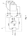
- FIG. 1 shows a simplified block diagram of a traditional four horn monopulse radar tracking system apparatus. Each pulse comprises four signals of equal amplitude. The four signals are radiated at the same time from four horns A, B, C and D that are grouped together in a cluster 2.
- the monopulse radar tracking system is designed so that the signal from each horn can be distinguished from those of the other horns, for example, by using different polarizations for each horn's signal.
- a comparator circuit 4 continuously compares the amplitude (or phase) of the return echo signals received by each horn with those received in the other horns.
- the comparator circuit 4 comprises waveguides and four hybrid junctions called "magic tees" (6, 8, 10 and 12 in Figure 1). Each junction receives two input signals and produces two output signals representing the sum and difference between the two input signals respectively. Accordingly junction 6 produces outputs (A+B) and (A-B) and junction 8 produces outputs (C+D) and (C-D).
- junction 10 produces outputs ⁇ o ((A+C)-(B+D)) and ⁇ El ((A+D)-(B+C)) and junction 12 produces outputs ⁇ 1 (A+B+C+D) and ⁇ Az ((A+B)-(C+D)).
- the beams from all four horns are summed (i.e. to generate the sum signal ⁇ 1 ).
- the resulting beam has a single lobe. Consequently, the radar will receive a large return signal from a target centered within the beam.
- the return signals from the four horns are combined by junctions 6, 8, 10 and 12, to produce broadside difference patterns. These difference patterns are characterised by the presence of a broad peak and a sharp null.
- the ⁇ Az output from junction 12 is used to determine the azimuth of the target.
- the ⁇ El output of junction 10 is used to determine the elevation of the target. If the target is located on the boresight axis, the amplitude of the target's return signal will be equalized in all four horns (i.e. the target will be located in the null region).
- the radar system's tracking circuit and power drives use this principle to track the motion of a target by moving the horn cluster 2 in the direction which equalises the amplitude of the return signal in all four horns A, B, C and D.
- the monopulse radar tracking system apparatus is typically bulky and expensive because it requires four independent (or partitioned) horns.
- US Patent Application No. 6,281,855 describes a single radiating element antenna structure capable of producing monopulse summation and difference far field patterns.
- the antenna operates by electromagnetically creating conditions for four separate radiating apertures within a single physical aperture. More specifically, the antenna employs four individually fed dielectric rods inserted into the horn and symmetrically disposed along the horn's major axis. When excited, the dielectric rods cause the electric fields inside the horn to distort and become asymmetrical thereby producing the summation and difference far field patterns.
- Circular polarization is a polarization state where the perpendicular components of an electrical field are of equal magnitude and have a 90° phase difference, so that the tip of the electric field vector traces a circle on the plane that is perpendicular to the direction of wave propagation.
- RHCP right-hand circularly polarized
- LHCP left-hand circularly polarized
- the electric field vector Whilst the electric field vector rotates in a circle in the plane perpendicular to the direction of wave propagation, along the propagation axis itself, the movement of the tip of the electric field vector describes a helix.
- a CP wave can be generated by passing a linearly polarized (LP) wave through a waveguide that contains an internal delay element positioned at 45° with respect to the LP wave.
- the components of the LP signal are thus decomposed into two orthogonal E vectors. Since the LP wave which passes through the delay element travels more slowly than through the waveguide, a phase difference is created between the portion of the wave which travels through the waveguide and the portion that travels through the delay element. If the waveguide and the delay element are of sufficient length a differential 90° phase shift can be induced between the two portions of the LP wave. Provided these are of equal magnitude then when these two portions of the LP wave are combined at the output of the waveguide, a circularly polarized signal is produced.
- the above delay-waveguide structure behaves like a low pass filter.
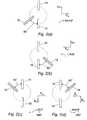
- Figures 2(a), 2(b), 2(c) and 2(d) show an alternative apparatus for generating CP waves, wherein the apparatus behaves more like a high pass filter.
- the apparatus comprises two metal posts 14 and 16 aligned at 180° to each other. Assuming that post 16 represents the 0° position, the apparatus further comprises a probe 18 positioned at 225°. If a voltage is applied to the probe 18, the resulting electric field resolves itself into two components, namely a vertical component E v which is directed along the post 16 and a horizontal component E H which is directed perpendicularly to the post 16. The vertical component E v must travel past the metal posts.
- the vertical component E v experiences a phase shift compared to E H .
- the metal posts are designed to ensure that this phase shift is 90°. Accordingly, in a manner akin to the above-mentioned waveguide-dielectric system, the wave produced from the output of the metal post-probe apparatus is circularly polarized. For the sake of clarity, the resulting wave is hereby defined to have a right-handed rotation (i.e. an RHCP wave)
- Figures 2(b), 2(c) and 2(d) show a similar apparatus to that of Figure 2(a).
- the probe 18 is located at the 135° position (relative to post 14) and the resulting wave is an LHCP wave.
- the probe 18 is located at the -45° position (relative to post 14) and the resulting wave is an LHCP wave with a 180° phase shift.
- the probe is located at the +45° position (relative to post 14) and the resulting wave is an RHCP wave with a 180° phase shift.
- an RHCP wave is combined with an LHCP wave
- the result is an LP wave.
- an RHCP wave is combined with an LHCP wave with a 180° phase shift
- the result is an LP wave with a 90° phase shift with respect to the case where no phase shifts are applied to either CP signal.
- a single aperture monopulse antenna that superimposes a plurality of phase shifted circularly polarized waves to produce multiple field patterns in a single antenna aperture.
- the single aperture monopulse antenna includes a metal post polarizer and a phasing network to generate the plurality of circularly polarized waves.
- the metal post polarizer comprises at least one probe and at least two posts, wherein the number of probes is substantially the same as the number of antenna apertures mimicked by the single aperture monopulse antenna.
- the metal post polarizer and the phasing network generate circularly polarized waves by applying a linear polarized wave to each of the at least one probes, to decompose the linearly polarized wave into orthogonal wave components at each of the at least one probes, and adding a phase shift to each of the orthogonal wave components at at least one of the at least one probes.
- the circularly polarized waves are superimposed in the aperture of the single aperture monopulse antenna.
- the phasing network comprises a 3dB Wilkinson power divider and at least two 90° branch line couplers.
- the single aperture horn antenna further comprises an axisymmetrical field radiating element.
- the axisymmetrical field radiating element is a Potter horn.
- the multiple aperture antenna field patterns are summation and difference patterns.
- a method of generating multiple field patterns from a single aperture antenna by the superposition of a plurality of phase shifted circularly polarized waves to create superimposed linearly polarized waves is provided.
- the superimposed linearly polarized waves produce summation and difference field patterns.
- the summation field pattern is produced by the superposition of at least one right circularly polarized wave with an equal number of left circularly polarized waves.
- the difference field pattern is produced by the superposition of at least one right circularly polarized wave with at least one left circularly polarized wave wherein the at least one left circularly polarized wave is provided with an appropriate phase shift.
- a single aperture monopulse antenna that superimposes phase shifted circularly polarized waves to produce multiple aperture antenna field patterns in a radar target tracking apparatus.
- a single aperture horn antenna which superimposes phase shifted circularly polarized waves to produce multiple aperture antenna field patterns in a mobile satellite communications system.
- a fifth aspect of the invention there is provided a use of a single aperture horn antenna which superimposes phase shifted circularly polarized waves to produce multiple aperture antenna field patterns in a vehicular anti-collision radar system.
- the present invention provides a simple single aperture antenna suitable for monopulse sensor applications.
- the invention provides a simple feed network which when used in combination with the Potter horn antenna allows sum (pencil) and difference (conical) patterns to be generated.
- the present invention employs a considerably simpler hardware structure than conventional monopulse radar systems, the antenna would be less expensive and considerably smaller and lighter than used in traditional monopulse radar systems. Furthermore, the present invention could be used in radar control, sensing or mobile satellite communications applications.
- a single aperture monopulse antenna 20 comprises a conical Potter horn 22 combined with an integral four port, probe fed, linear to circular polarizer 24 and a phasing network 25.
- the probes of the linear to circular polarizer 24 When excited through the phasing network 25, the probes of the linear to circular polarizer 24 generate combinations of CP waves that combine in the far field of the single aperture monopulse antenna 20 to produce LP summation ( ⁇ ) and difference ( ⁇ ) field patterns similar to those employed in traditional monopulse radar tracking systems.
- the linear to circular polarizer 24 is based on a modified version of the metal post-probe apparatus shown in Figures 2(a) to 2(d).
- the linear to circular polarizer 24 is a differential phase-shifter configured to act as a coaxially fed polarizer (A. Fox, PIRE, 35(12), 1947, p1489-1498 and H. Schrank, IEEE Antennas and Propagation Society Newsletter, Oct. 1984, pp. 12).
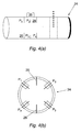
- the linear to circular polarizer 24 comprises four probes P 1 ,P 2 , P 3 and P 4 arranged symmetrically around the circumference of the linear to circular polarizer 24 and extending into the interior of the linear to circular polarizer 24.
- the linear to circular polarizer 24 also comprises two metal posts 26 and 28 extending into the interior of the linear to circular polarizer 24 and disposed between opposing pairs of probes, so that post 26 is positioned and equispaced between probes P 1 and P 2 and post 28 is positioned and equispaced between probes P 3 and P 4 .
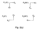
- post 26 will henceforth be defined as the 0° position on the linear to circular polarizer 24. Accordingly, probes P 1 , P 2 , P 3 and P 4 are disposed at the -45°, 45°, 135° and 225° positions respectively on the linear to circular polarizer 24.
- a voltage i.e. an LP wave
- P 1 for a RHCP wave
- P 2 for an LHCP wave
- the nearest post i.e. post 26 or 28
- an RHCP or LHCP wave is generated.
- the phases of the LP waves applied to each probe are controlled by phasing network 25.
- the phasing network comprises a 3dB Wilkinson Power divider and two 90° branch line couplers. This circuit design eliminates the need for a more complex phasing matrix circuit design.
- the monopulse radar tracking system employs broadside summation ⁇ and difference ⁇ far field patterns to detect and locate a target.
- the four probes P 1 , P 2 , P 3 and P 4 are fed with uniform amplitude LP waves.
- the phases of the LP waves applied to each probe are altered by the phasing network 25 in accordance with the phase relationships shown in Table 1 below.
- a Potter horn 22 is used as the radiating element of the single aperture monopulse antenna.
- a Potter Horn 22 is a modified version of a standard conical horn antenna that operates by ensuring that a small component of the dominant TE 11 mode of the waveguide is converted to the TM 11 mode within the horn circular waveguide structure. These two modes are in anti-phase in the upper and lower boundary regions of the horn. Consequently, the two modes partially cancel each other when they combine in the aperture. This increases the edge taper in the E plane thereby broadening the pattern to give an axisymmetric far-field beam (in contrast with the elliptical far-field beam of a conventional conical horn).
- a change in the waveguide dimensions near the horn throat provides the simplest means to generate a required additional mode component [P.D. Potter, Microwave J., 1963, 6, pp.71-78].
- the single aperture monopulse antenna is not limited to the production of ⁇ and ⁇ far field patterns. Instead, the phase relationships employed in the CP wave superposition technique described above could be modified to mimic many far field patterns from a single aperture.
- a prototype metal post loaded polarizer was designed using 3D EM software (MICRO-STRIPES Version 6.0, Flomerics Limited, 81 Bridge Road, Hampton Court, Surrey, KT8 9HH, U.K.) and constructed for I-band operation.
- the polarizer has a diameter and length of 26mm and 79mm respectively.
- the polarizer is provided with metal posts that have a diameter and depth of 3mm and 5.3mm respectively.
- SMA sub-miniature Amphenol
- each of the phasing network output ports were connected to a 50 ⁇ resistor.
- the phasing network return loss is better than -15dB over the operating frequency band.
- Table 2 compares the theoretical phase applied by the phasing network to each probe in the polarizer (denoted by Th) with the actual measured phase response (Ms) of the feed network at 8.6GHz.
- 8.6GHz was selected as the signal frequency since it provided the best amplitude balance, ⁇ 0.06dB worst case relative magnitude difference between the ports, as well as best match to the theoretical feed port phase requirement.
- the single aperture monopulse antenna is not limited to operation at 8.6GHz and is instead potentially operable over a wide selection of frequencies.
- Figures 7 and 8 respectively show the results from measurements of the linearly polarized far field summation and difference patterns radiated from the prototype single aperture monopulse antenna at a frequency of 8.6GHz.
- the principal plane for the co-polar far field radiation cuts was selected to yield a maximum radiated field strength and is as expected to be coincident with the 45° tilt angle.
- Table 3 lists the principal far field pattern metrics (full patterns omitted for brevity), calculated for the prototype single aperture monopulse antenna for 8.4 GHz and 8.5 GHz waves.
- Principal far field metrics calculated for the prototype single aperture monopulse antenna Frequency (GHz) 3dB BW (Deg.) Gain (dBi) Cross polarization at boresight (dB) 8.4 19.8 18.4 -22 8.5 19.5 18.6 -29 8.6 19.2 18.7 -31
- the gain was 18.6dBi, and cross polar far field levels were below -29dB, whilst for the difference far field pattern the depth of the null was 26dB at 8.6GHz.
Landscapes
- Variable-Direction Aerials And Aerial Arrays (AREA)
- Waveguide Aerials (AREA)
Applications Claiming Priority (2)
| Application Number | Priority Date | Filing Date | Title |
|---|---|---|---|
| GB0405112 | 2004-03-06 | ||
| GBGB0405112.4A GB0405112D0 (en) | 2004-03-06 | 2004-03-06 | Single aperature monopulse antenna |
Publications (1)
| Publication Number | Publication Date |
|---|---|
| EP1585194A1 true EP1585194A1 (de) | 2005-10-12 |
Family
ID=32088865
Family Applications (1)
| Application Number | Title | Priority Date | Filing Date |
|---|---|---|---|
| EP05251228A Withdrawn EP1585194A1 (de) | 2004-03-06 | 2005-03-01 | Monopulsantenne mit einer Apertur |
Country Status (3)
| Country | Link |
|---|---|
| US (1) | US7277061B2 (de) |
| EP (1) | EP1585194A1 (de) |
| GB (1) | GB0405112D0 (de) |
Cited By (3)
| Publication number | Priority date | Publication date | Assignee | Title |
|---|---|---|---|---|
| WO2018125700A1 (en) * | 2016-12-31 | 2018-07-05 | Hughes Network Systems, Llc | Method and system for using a receive planar phased array antenna on a communication platform to estimate a pointing error of the antenna and to orient its boresight towards the transmitter. |
| CN109643852A (zh) * | 2016-10-28 | 2019-04-16 | 华为技术加拿大有限公司 | 单层端射圆极化基片集成波导喇叭天线 |
| CN111969335A (zh) * | 2020-08-16 | 2020-11-20 | 西安电子科技大学 | 一种共形双极化二维单脉冲端射阵列天线 |
Families Citing this family (4)
| Publication number | Priority date | Publication date | Assignee | Title |
|---|---|---|---|---|
| US8077103B1 (en) * | 2007-07-07 | 2011-12-13 | The United States Of America As Represented By The Administrator Of The National Aeronautics And Space Administration | Cup waveguide antenna with integrated polarizer and OMT |
| FR3042317B1 (fr) * | 2015-10-09 | 2017-12-01 | Thales Sa | Cornet rayonnant compact multifrequences, source rayonnante et antenne comportant un tel cornet rayonnant |
| US11493620B2 (en) | 2020-02-25 | 2022-11-08 | The Boeing Company | Distributed monopulse radar antenna array for collision avoidance |
| US11626666B2 (en) * | 2020-07-31 | 2023-04-11 | Hughes Network Systems, Llc | Integrated polarization converter and feed horn |
Citations (4)
| Publication number | Priority date | Publication date | Assignee | Title |
|---|---|---|---|---|
| US3560976A (en) * | 1968-08-21 | 1971-02-02 | Rca Corp | Feed system |
| US4473828A (en) * | 1981-03-25 | 1984-09-25 | Licentia Patent-Verwaltungs-Gmbh | Microwave transmission device with multimode diversity combined reception |
| JPH0629721A (ja) * | 1992-07-08 | 1994-02-04 | Nec Corp | 円偏波ホーンアンテナ |
| US5298908A (en) * | 1987-11-27 | 1994-03-29 | Unisys Corporation | Interference nulling system for antennas |
Family Cites Families (4)
| Publication number | Priority date | Publication date | Assignee | Title |
|---|---|---|---|---|
| US3569870A (en) * | 1968-08-21 | 1971-03-09 | Rca Corp | Feed system |
| US3699583A (en) * | 1971-07-26 | 1972-10-17 | Int Standard Electric Corp | Phase correction apparatus for circular polarization operation monopulse antenna horn |
| US4096482A (en) * | 1977-04-21 | 1978-06-20 | Control Data Corporation | Wide band monopulse antennas with control circuitry |
| JP2001007641A (ja) * | 1999-06-24 | 2001-01-12 | Mitsubishi Electric Corp | モノパルスアンテナ装置およびアンテナ構造 |
-
2004
- 2004-03-06 GB GBGB0405112.4A patent/GB0405112D0/en not_active Ceased
-
2005
- 2005-03-01 EP EP05251228A patent/EP1585194A1/de not_active Withdrawn
- 2005-03-03 US US11/071,423 patent/US7277061B2/en not_active Expired - Fee Related
Patent Citations (4)
| Publication number | Priority date | Publication date | Assignee | Title |
|---|---|---|---|---|
| US3560976A (en) * | 1968-08-21 | 1971-02-02 | Rca Corp | Feed system |
| US4473828A (en) * | 1981-03-25 | 1984-09-25 | Licentia Patent-Verwaltungs-Gmbh | Microwave transmission device with multimode diversity combined reception |
| US5298908A (en) * | 1987-11-27 | 1994-03-29 | Unisys Corporation | Interference nulling system for antennas |
| JPH0629721A (ja) * | 1992-07-08 | 1994-02-04 | Nec Corp | 円偏波ホーンアンテナ |
Non-Patent Citations (1)
| Title |
|---|
| PATENT ABSTRACTS OF JAPAN vol. 018, no. 240 (E - 1545) 9 May 1994 (1994-05-09) * |
Cited By (7)
| Publication number | Priority date | Publication date | Assignee | Title |
|---|---|---|---|---|
| CN109643852A (zh) * | 2016-10-28 | 2019-04-16 | 华为技术加拿大有限公司 | 单层端射圆极化基片集成波导喇叭天线 |
| WO2018125700A1 (en) * | 2016-12-31 | 2018-07-05 | Hughes Network Systems, Llc | Method and system for using a receive planar phased array antenna on a communication platform to estimate a pointing error of the antenna and to orient its boresight towards the transmitter. |
| US10051487B2 (en) | 2016-12-31 | 2018-08-14 | Hughes Network Systems, Llc | Method and system for orienting a phased array antenna |
| GB2572511A (en) * | 2016-12-31 | 2019-10-02 | Hughes Network Systems Llc | Method and system for using a receive planar phased array antenna on a communication platform to estimate a pointing error of the antenna |
| US10555185B2 (en) | 2016-12-31 | 2020-02-04 | Hughes Network Systems, Llc | Method and system for orienting a phased array antenna |
| GB2572511B (en) * | 2016-12-31 | 2021-11-03 | Hughes Network Systems Llc | Method and system for using a receive planar phased array antenna on a communication platform to estimate a pointing error of the antenna |
| CN111969335A (zh) * | 2020-08-16 | 2020-11-20 | 西安电子科技大学 | 一种共形双极化二维单脉冲端射阵列天线 |
Also Published As
| Publication number | Publication date |
|---|---|
| US7277061B2 (en) | 2007-10-02 |
| US20050200548A1 (en) | 2005-09-15 |
| GB0405112D0 (en) | 2004-04-07 |
Similar Documents
| Publication | Publication Date | Title |
|---|---|---|
| Meredov et al. | Screen-printed, flexible, parasitic beam-switching millimeter-wave antenna array for wearable applications | |
| Lipsky | Microwave passive direction finding | |
| Davis et al. | Linearly polarized radial-line slot-array antennas with improved return-loss performance | |
| CA2029762C (en) | Dual mode antenna apparatus having slotted waveguide and broadband arrays | |
| Hamberger et al. | A mixed circular/linear dual-polarized phased array concept for automotive radar—Planar antenna designs and system evaluation at 78 GHz | |
| JP2851338B2 (ja) | リニア・フェイズドアレイ・アンテナのための角度位置決め用レーダシステム | |
| US7277061B2 (en) | Single aperture monopulse antenna | |
| US5900843A (en) | Airborne VHF antennas | |
| Yang et al. | A single-layer SIW slots array monopulse antenna excited by a dual-mode resonator | |
| CN108173002A (zh) | 一种基于共形Vivaldi天线的复合极化敏感阵列装置 | |
| Lechtreck | Effects of coupling accumulation in antenna arrays | |
| Liang et al. | Synthesis and measurement of a circular-polarized deflection OAM vortex beam with sidelobe suppression array | |
| Kinsey | An edge-slotted waveguide array with dual-plane monopulse | |
| Shafai et al. | Multiple phase center performance of reflector antennas using a dual mode horn | |
| Jung et al. | Dual-band horn array design using a helical exciter for mobile satellite communication terminals | |
| Chepala et al. | X-band Planar Monopulse Microstrip Antenna array with improved null-depth | |
| Subbarao et al. | Single aperture monopulse horn antenna | |
| US4148035A (en) | Subwavelength monopulse antenna | |
| Patel | Inexpensive multi-mode satellite tracking feed antenna | |
| Knott | Antenna design and beamforming for a conformal antenna array demonstrator | |
| Rao et al. | Research on GPS Antennas at MITRE | |
| Eck | Compact antennas and arrays for unmanned air systems | |
| JP2012093321A (ja) | モノパルス給電回路 | |
| Karami et al. | Mm-Wave Monopulse Radar System for Detecting Space Debris in Satellite Exploration Missions | |
| US20230266436A1 (en) | High Resolution 4-D Millimeter-Wave Imaging Radar |
Legal Events
| Date | Code | Title | Description |
|---|---|---|---|
| PUAI | Public reference made under article 153(3) epc to a published international application that has entered the european phase |
Free format text: ORIGINAL CODE: 0009012 |
|
| AK | Designated contracting states |
Kind code of ref document: A1 Designated state(s): AT BE BG CH CY CZ DE DK EE ES FI FR GB GR HU IE IS IT LI LT LU MC NL PL PT RO SE SI SK TR |
|
| AX | Request for extension of the european patent |
Extension state: AL BA HR LV MK YU |
|
| 17P | Request for examination filed |
Effective date: 20060411 |
|
| AKX | Designation fees paid |
Designated state(s): AT BE BG CH CY CZ DE DK EE ES FI FR GB GR HU IE IS IT LI LT LU MC NL PL PT RO SE SI SK TR |
|
| 17Q | First examination report despatched |
Effective date: 20070116 |
|
| STAA | Information on the status of an ep patent application or granted ep patent |
Free format text: STATUS: THE APPLICATION IS DEEMED TO BE WITHDRAWN |
|
| 18D | Application deemed to be withdrawn |
Effective date: 20090516 |