EP1584949A1 - Vorrichtung und System zum Auslesen von in einer stimulierbaren Phosphorschicht gespeicherter Röntgeninformationen - Google Patents
Vorrichtung und System zum Auslesen von in einer stimulierbaren Phosphorschicht gespeicherter Röntgeninformationen Download PDFInfo
- Publication number
- EP1584949A1 EP1584949A1 EP04101426A EP04101426A EP1584949A1 EP 1584949 A1 EP1584949 A1 EP 1584949A1 EP 04101426 A EP04101426 A EP 04101426A EP 04101426 A EP04101426 A EP 04101426A EP 1584949 A1 EP1584949 A1 EP 1584949A1
- Authority
- EP
- European Patent Office
- Prior art keywords
- light source
- control
- control device
- control parameter
- light sources
- Prior art date
- Legal status (The legal status is an assumption and is not a legal conclusion. Google has not performed a legal analysis and makes no representation as to the accuracy of the status listed.)
- Granted
Links
- OAICVXFJPJFONN-UHFFFAOYSA-N Phosphorus Chemical compound [P] OAICVXFJPJFONN-UHFFFAOYSA-N 0.000 title claims abstract description 32
- 230000000638 stimulation Effects 0.000 claims abstract description 14
- 230000001276 controlling effect Effects 0.000 claims description 9
- 238000010276 construction Methods 0.000 claims description 7
- 230000008859 change Effects 0.000 claims description 5
- 230000001105 regulatory effect Effects 0.000 claims description 2
- 230000002123 temporal effect Effects 0.000 description 11
- 230000006399 behavior Effects 0.000 description 6
- 230000001419 dependent effect Effects 0.000 description 5
- 230000003287 optical effect Effects 0.000 description 4
- 238000010586 diagram Methods 0.000 description 2
- 230000006870 function Effects 0.000 description 2
- 230000004913 activation Effects 0.000 description 1
- 230000008901 benefit Effects 0.000 description 1
- 239000003990 capacitor Substances 0.000 description 1
- 230000008878 coupling Effects 0.000 description 1
- 238000010168 coupling process Methods 0.000 description 1
- 238000005859 coupling reaction Methods 0.000 description 1
- 230000023077 detection of light stimulus Effects 0.000 description 1
- 230000003292 diminished effect Effects 0.000 description 1
- 230000000694 effects Effects 0.000 description 1
- 238000011156 evaluation Methods 0.000 description 1
- 238000009434 installation Methods 0.000 description 1
- 238000004519 manufacturing process Methods 0.000 description 1
- 238000005259 measurement Methods 0.000 description 1
- 230000004044 response Effects 0.000 description 1
- 230000004936 stimulating effect Effects 0.000 description 1
- 230000036962 time dependent Effects 0.000 description 1
Images

Classifications
-
- G—PHYSICS
- G01—MEASURING; TESTING
- G01T—MEASUREMENT OF NUCLEAR OR X-RADIATION
- G01T1/00—Measuring X-radiation, gamma radiation, corpuscular radiation, or cosmic radiation
- G01T1/16—Measuring radiation intensity
- G01T1/20—Measuring radiation intensity with scintillation detectors
- G01T1/2012—Measuring radiation intensity with scintillation detectors using stimulable phosphors, e.g. stimulable phosphor sheets
- G01T1/2014—Reading out of stimulable sheets, e.g. latent image
Definitions
- the invention relates to a device and a corresponding system for Reading x-ray information stored in a stimulable phosphor layer according to the preamble of claim 1.
- X-ray information can be stored in so-called storage phosphors, wherein the passing through an object, such as a patient, passing X-radiation is stored as a latent image in a phosphor layer.
- the phosphor layer with stimulation light irradiated while stimulated to emit emission light.
- the emission light whose intensity corresponds to the image stored in the phosphor layer, is detected by an optical detector and converted into electrical signals.
- the electrical signals are processed as needed and finally for evaluation, in particular for medical diagnostic purposes, provided by an appropriate output device such.
- Such line light sources often include a plurality of individual light sources arranged in a row, the individual light cones overlap on the linear area of the phosphor layer.
- the invention is based on the idea of the intensity of the light sources during controlling the operation of the device, controlling the intensity of each individual light source in response to a control parameter.
- the control is preferably continuous, i. throughout the operation from switching on to switching off the light sources.
- the - preferably for all light sources of the stimulation light source same - control parameters here determined by a reference light source, which one the respective light sources similar or identical with this behavior. hereby is a high temporal constancy and spatial homogeneity of the stimulation light in the illuminated area of the phosphor layer with simultaneous simple Construction achieved.
- the Control device the reference light source and a sensor for detection of light emitted from the reference light source and for generating one of Intensity of the detected light corresponding reference signal, from which it can derive the control parameter.
- This will be easy detects the temporal behavior of the reference light source, from which of the for the Controlling the light sources derived control parameters are derived can.
- the control device for deriving the control parameter from a deviation of the reference signal from a reference setpoint is trained.
- the control device preferably has a control loop on which the deviation of the reference signal from the reference setpoint by a change of a reference light source voltage applied to the reference light source can compensate.
- the loop becomes the intensity the reference light source is automatically maintained at a predefinable setpoint, by regulating the reference light source voltage accordingly, d. H. increased or diminished, will.
- the individual light sources can be the one for controlling the intensity then the individual light sources used control parameters then simply off derived from the reference light source voltage.
- control device a subtracter for forming a difference between the reference light source voltage and the reference setpoint and the control parameter corresponds to this difference formed.
- the control parameter is a non-zero value when the reference light source voltage, in which the reference light source actually operated is, from the voltage corresponding to the reference setpoint, with which the Reference light source to achieve a desired intensity operated should, deviates.
- the reference setpoint corresponds to a reference input voltage, which is applied to an input of the control loop.
- control device for each of the light sources in each case comprises a control unit, which a voltage applied to the respective light source light source voltage in dependence from the control parameter. This will achieve that the light source voltage applied to a light source for each Light source can be adjusted individually. The intensity of the individual light sources is thus individually controllable.
- control unit has an adder for forming the Sum of the control parameter and a light source input voltage of having respective light source, wherein the voltage applied to the respective light source Light source voltage this sum corresponds. This will change the setting the light source voltage of each individual light source depending on the control parameter realized in a simple way.
- the reference light source and the individual light sources are respectively same type of construction. This ensures that the reference light source, based which of the control parameters is determined, has a temporal behavior, which is substantially identical to that of the individual light sources. Any changes in the intensity of the light sources during operation will be compensated in this way with a particularly high reliability and thus avoided.
- the reference light source with the light sources thermally to pair. Because intensity fluctuations of the individual light sources in high Dimensions caused by thermal effects, intensity fluctuations prevents the individual light sources characterized with particularly high reliability.
- a memory is provided in which of the control parameters can be stored and on which the Control device can access.
- the control device can at this Form a separate unit and independent of the invention Device determine the control parameter, which is stored in memory can be. The control device can then during operation of the invention Device access the memory and the required Control parameters received. This allows for the installation of a corresponding Control device can be dispensed with in the device according to the invention.
- control device for determining the control parameter in dependence from the time after turning on the reference light source and / or formed by the ambient temperature in the vicinity of the reference light source is.
- the time dependent and / or ambient temperature dependent control parameters can be determined in this embodiment in the separate control device and stored in memory.
- the Control device on the memory which preferably integrates in the device is, access and thereby receive those control parameters, which of the respective Time after switching on the light sources and / or the ambient temperature in the vicinity of the light sources during operation of the light sources.
- the device here are corresponding measuring devices for Measurement of the time or the ambient temperature provided.
- the system according to the invention comprises in addition to those described above Device and its embodiments, the corresponding control device for determining the control parameter on the basis of light, which of the Reference light source is emitted.
- control device can completely integrated in a reader for reading phosphor layers be.
- the control parameter is preferably determined in real time, i. during operation of the individual light sources.
- control device be integrated in the reader, while the control device outside the Reader is arranged.
- control parameter in particular determined separately from the operation of the individual light sources and then stored in a memory. The determination of the control parameter is preferably carried out depending on the time after the reference light source is switched on and / or the ambient temperature in the vicinity of the reference light source in the manner already described above.
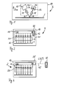
- Fig. 1 shows a side view of the device according to the invention for reading the X-ray information stored in a phosphor layer 1.
- the device has a line light source 11 for generating stimulation light 12, which by means of a first optical device 13 on the phosphor layer. 1 is focused, wherein a perpendicular to the plane of the figure extending linear Area of the phosphor layer is irradiated with stimulation light 12. In this Area the phosphor layer 1 is excited to emit emission light 14, which of a detector 17, which as a likewise perpendicular to the plane of the figure extending line-shaped detector is formed detected. To focus of the emission light 14 to the detector 17 is a corresponding one second optical device 15 is provided.
- a filter device 16 is for emission light 14 substantially transmissive and for stimulation light 12 substantially impermeable. This ensures that the from the detector 17th to be detected emission light 14 is not reflected by the phosphor layer 1 or scattered portions of the stimulation light 12 is falsified.
- the device according to the invention is in a housing 19 of a corresponding Reader 2 integrated for reading phosphor layers.
- the reader 2 may in this case be designed such that the respectively to be read phosphor layer 1 is read before reading into the reader 2 and after the Read out again from the reader 2 is removed.
- the housing 19 of a such reader 2 has for this purpose a corresponding opening (not shown) through which a cassette with the phosphor layer therein 1 can be supplied.
- the reader 2 as so-called n-th be formed cassetteless system in which the phosphor layer. 1 is firmly integrated in the housing 19.
- Such a system can be used when recording X-rays are used as a conventional X-ray cassette but compared to such an advantage that they are not a special Reader must be supplied, but the required read head 18 already has as an integral part.
- Those with such a cassette-less System stored in an X-ray in the phosphor layer 1 Information can then be readily cassette handling or the like be read out directly.
- Fig. 2 shows a front view of a first embodiment of the in one Reader 2 integrated device according to the invention.
- the illustrated front view in this case runs in the direction B of the view shown in Fig. 1.
- the line light source 11 has several in one Row of light sources 20, each emitting stimulation light 12, which focuses on the phosphor layer 1 by the first optical device 13 becomes.
- a total of seven light sources 20 can be seen.
- the number of light sources is usually clear higher and is preferably between about 30 and 50 light sources 20 per line light source 11.
- the individual light sources 20 are preferably Laser diodes (LDs) or very bright light-emitting diodes (LEDs).
- LDs Laser diodes
- LEDs very bright light-emitting diodes
- control device 30th For controlling the individual light sources 20 is a control device 30th provided which control the respective intensities of the light sources 20 individually can. According to the invention, this activation takes place by using a Control parameter, which is determined in a control device 40.
- the control device 40 has for this purpose a reference light source 41 and a Sensor 42, which detects the output from the reference light source 41 light and converted into a corresponding reference signal. From the reference signal is derived in the control device 40 of the control parameters, the then in the controller 30 to adjust the intensities of the individual Light sources 20 can be used.
- Fig. 3 shows a circuit diagram for controlling the intensity of the invention individual light sources 20.
- the individual components of the circuit shown are summarized essentially in two skin components, namely in the Control device 30 on the one hand and the control device 40 on the other.
- the reference light source 41 is operated with a reference light source voltage UR and emits light detected by the sensor 42 and into the reference signal R corresponding to the intensity of the light is converted.
- the reference signal R is by means of a regulator circuit 43 with a reference input voltage UER, which corresponds to the reference setpoint compared. at a deviation of the reference signal R from the reference setpoint UER is by means of the regulator circuit 43, the reference light source voltage UR and thus the intensity of the light emitted by the reference light source changed so that this deviation is compensated.
- the instantaneous intensity of the reference light source 41 emitted light higher than the reference setpoint UER corresponds,
- the reference light source voltage UR so far reduced until the intensity corresponding reference signal R with the Reference setpoint UER is identical.
- the reference light source voltage UR obtained in this control circuit is combined supplied to the reference setpoint UER a subtractor 44, which the difference between the two voltages forms. This difference then serves as a control parameter C.
- the control parameter C obtained in this way becomes the control device 30 supplied.
- This has control units 31, wherein for each of the light sources 20, a single control unit 31 is provided.
- the control units 31 are each designed as adders, in which the control parameter C with a light source input voltage UEL too a light source voltage UL applied to the respective light source 20, is added.
- the individual light source input voltages UEL are generally different, to slight differences in intensity, even with light sources 20 same type of construction may occur. These in general diverging light source input voltages UEL are preferably already in the production of the device according to the invention accordingly set. Because this so-called type spread of intensity individual light sources 20 same type of construction during operation of the light sources 20 but usually does not change much, is a change in the light source input voltages UEL usually not required during operation.
- temporal intensity fluctuations in the present circuit for example, due to temperature-dependent effects
- the operation of the individual light sources 20 by using the control parameter C and corresponding adjustment of the respective light source voltage UL compensated.
- the invention is based on the surprising finding that that the temporal intensity behavior of the light sources 20 of the same type during the operation is substantially identical.
- the inventive leads Control of the individual light sources 20 with only one control parameter C to a very reliable compensation of intensity fluctuations at the same time simple construction.
- control of the intensity of the individual light sources 20 in the control device 30 by using the in the control device 40th determined control parameter C is an implementation of the so-called Master-slave principle.
- control device 40 determined control parameters C are stored in a memory 35.
- a direct connection between the control device 30 and the control device 40 is then no longer necessary. Rather, this can be Execution of the control parameters C, preferably as a function of time and the ambient temperature of the reference light source 41 is determined and in memory 35 are stored.
- the controller 30 then to, from the time and the ambient temperature dependent, control parameter C in the memory 35 and derives therefrom the individual light source voltages UL of the light sources 20 from.
- the illustrated circuit includes besides the components described above other electronic components, such.
- B. resistors and a capacitor which accounts for different variants of the circuit according to the invention or different dimensions. This as well as the provision other unillustrated components are within the scope of customary practice Knowledge and is therefore not described in detail.
- Fig. 4 shows a front view of a second embodiment of the invention Contraption. This embodiment is different from the shown in Fig. 2 in that the control device 40 is not part of the reader 2, but separated from it and independent can be operated.
- the control parameter C determined as in the control device shown in Fig. 2.
- the control parameter C becomes different Times t and at different ambient temperatures T determined and as dependent on the time t and the ambient temperature T Data field C (t, T), for example as a so-called lookup table, in one Memory 35 stored.
- the memory 35 in the reader 2 integrated and with a data line 45 with the control device 40 verbu n-the.
- the memory 35 but also outside of the housing 19 of the Reader 2 are, for example, in a central file server, on which can access multiple readers.
- the ambient temperatures T at which the control parameter C is determined typically range between about 10 and 60 degrees Celsius (° C), in particular between 20 and 40 ° C.
- the control parameter C becomes in this case preferably determined in temperature steps .DELTA.T of about 1 to 5 ° C.
- the Time duration within which the control parameter C determines as a function of the time t is typically between about 0.5 and 100 milliseconds (ms), especially in the range of 1 to 5 ms.
- the control parameter C is preferably determined in time intervals ⁇ t between 50 and 200 microseconds ( ⁇ s).
- the control device 30 has suitable measuring devices in this example (not shown) for detecting the respective time and / or ambient temperature t and T during operation of the light sources 20 and attacks the control parameters C (t, T) corresponding to these two parameters in the memory 35 too.
- the control parameter C obtained in this case is finally in the inventive Controlling the intensity of the individual light sources 20 used.
- the line light source 11 of the device according to the invention according to the figures 1, 2 and 4 is preferably operated pulsed, wherein the individual light sources 20 alternately, preferably periodically, switched on and off. Due to the associated temporally fluctuating heat development changes also the ambient temperature and thus the temporal intensity behavior the light sources 20 accordingly.
Landscapes
- Physics & Mathematics (AREA)
- Health & Medical Sciences (AREA)
- Life Sciences & Earth Sciences (AREA)
- General Physics & Mathematics (AREA)
- High Energy & Nuclear Physics (AREA)
- Molecular Biology (AREA)
- Spectroscopy & Molecular Physics (AREA)
- Facsimile Scanning Arrangements (AREA)
- Semiconductor Lasers (AREA)
- Radiography Using Non-Light Waves (AREA)
Abstract
Description
- Fig. 1
- eine Seitenansicht der erfindungsgemäßen Vorrichtung;
- Fig. 2
- eine Vorderansicht eines ersten Ausführungsbeispiels der erfindungsgemäßen Vorrichtung;
- Fig. 3
- einen Schaltplan zur erfindungsgemäßen Steuerung der Intensität der einzelnen Lichtquellen; und
- Fig. 4
- eine Vorderansicht eines zweiten Ausführungsbeispiels der erfindungsgemäßen Vorrichtung.
Claims (13)
- Vorrichtung zum Auslesen von in einer stimulierbaren Phosphorschicht (1) gespeicherter Röntgeninformation mitgekennzeichnet durchmehreren Lichtquellen (20) zur Aussendung von Stimulationslicht (12), welches die Phosphorschicht (1) zur Aussendung von Emissionslicht (14) anregen kann undeinem Detektor (17) zur Erfassung von von der Phosphorschicht (1) ausgesandtem Emissionslicht (14),
eine Steuerungseinrichtung (30) zur Steuerung der Intensität der Lichtquellen (20) unter Heranziehung eines Steuerparameters (C), welcher in einer Regelungseinrichtung (40) anhand einer Referenzlichtquelle (41) ermittelt wird. - Vorrichtung nach Anspruch 1, dadurch gekennzeichnet, dass die Regelungseinrichtung (40)umfasst und zur Ableitung des Steuerparameters (C) aus dem Referenzsignal (R) ausgebildet ist.die Referenzlichtquelle (41) undeinen Sensor (42) zur Erfassung von von der Referenzlichtquelle (41) ausgesandtem Licht und zur Erzeugung eines der Intensität des erfassten Lichts entsprechenden Referenzsignals (R)
- Vorrichtung nach Anspruch 2, dadurch gekennzeichnet, dass die Regelungseinrichtung (40) zur Ableitung des Steuerparameters (C) aus einer Abweichung des Referenzsignals (R) von einem Referenzsollwert (UER) ausgebildet ist.
- Vorrichtung nach Anspruch 3, dadurch gekennzeichnet, dass die Regelungseinrichtung (40) einen Regelkreis (43) umfasst, welcher die Abweichung des Referenzsignals (R) von dem Referenzsollwert (UER) durch eine Veränderung einer Referenzlichtquellenspannung (UR), welche an der Referenzlichtquelle (41) anliegt, kompensieren kann.
- Vorrichtung nach Anspruch 4, dadurch gekennzeichnet, dass die Regelungseinrichtung (40) zur Ableitung des Steuerparameters (C) aus der Referenzlichtquellenspannung (UR) ausgebildet ist.
- Vorrichtung nach Anspruch 4 oder 5, dadurch gekennzeichnet, dass die Regelungseinrichtung (40) einen Subtrahierer (44) zur Bildung einer Differenz zwischen der Referenzlichtquellenspannung (UR) und dem Referenzsollwert (UER) aufweist und der Steuerparameter (C) der gebildeten Differenz entspricht.
- Vorrichtung nach einem der vorangehenden Ansprüche, dadurch gekennzeichnet, dass die Steuerungseinrichtung (30) für jede der Lichtquellen (20) jeweils eine Steuereinheit (31) umfasst, welche eine an der jeweiligen Lichtquelle (20) anliegende Lichtquellenspannung (UL) in Abhängigkeit von dem Steuerparameter (C) einstellen kann.
- Vorrichtung nach Anspruch 7, dadurch gekennzeichnet, dass die Steuereinheit (31) einen Addierer zur Bildung der Summe aus dem Steuerparameter (C) und einer Lichtquelleneingangsspannung (UEL) der jeweiligen Lichtquelle (20) aufweist und die an der jeweiligen Lichtquelle (20) anliegende Lichtquellenspannung (UL) dieser Summe entspricht.
- Vorrichtung nach einem der vorangehenden Ansprüche, dadurch gekennzeichnet, dass die Referenzlichtquelle (41) und die Lichtquellen (20) gleichen Bautyps sind.
- Vorrichtung nach einem der vorangehenden Ansprüche, dadurch gekennzeichnet, dass die Referenzlichtquelle (41) mit den Lichtquellen (20) thermisch gekoppelt ist.
- Vorrichtung nach einem der vorangehenden Ansprüche, dadurch gekennzeichnet, dass ein Speicher (35) vorgesehen ist, in welchem der Steuerparameter (C) gespeichert werden kann und auf welchen die Steuerungseinrichtung (30) zugreifen kann.
- Vorrichtung nach einem der vorangehenden Ansprüche, dadurch gekennzeichnet, dass die Regelungseinrichtung (40) zur Ermittlung des Steuerparameters (C) in Abhängigkeit von der Zeit (t) und/oder der Umgebungstemperatur (T) ausgebildet ist.
- System zum Auslesen von in einer stimulierbaren Phosphorschicht (1) gespeicherter Röntgeninformation, umfassendeine Vorrichtung nach einem der vorangehenden Ansprüche unddie Regelungseinrichtung (40), welche den Steuerparameter (C) anhand der Referenzlichtquelle (41) ermitteln kann.
Priority Applications (4)
| Application Number | Priority Date | Filing Date | Title |
|---|---|---|---|
| AT04101426T ATE435435T1 (de) | 2004-04-06 | 2004-04-06 | Vorrichtung und system zum auslesen von in einer stimulierbaren phosphorschicht gespeicherten röntgeninformationen |
| EP04101426A EP1584949B1 (de) | 2004-04-06 | 2004-04-06 | Vorrichtung und System zum Auslesen von in einer stimulierbaren Phosphorschicht gespeicherten Röntgeninformationen |
| DE502004009688T DE502004009688D1 (de) | 2004-04-06 | 2004-04-06 | Vorrichtung und System zum Auslesen von in einer stimulierbaren Phosphorschicht gespeicherten Röntgeninformationen |
| US11/079,306 US7157728B2 (en) | 2004-04-06 | 2005-03-14 | Equipment and system for reading out X-ray information stored in a stimulatable phosphor layer |
Applications Claiming Priority (1)
| Application Number | Priority Date | Filing Date | Title |
|---|---|---|---|
| EP04101426A EP1584949B1 (de) | 2004-04-06 | 2004-04-06 | Vorrichtung und System zum Auslesen von in einer stimulierbaren Phosphorschicht gespeicherten Röntgeninformationen |
Publications (2)
| Publication Number | Publication Date |
|---|---|
| EP1584949A1 true EP1584949A1 (de) | 2005-10-12 |
| EP1584949B1 EP1584949B1 (de) | 2009-07-01 |
Family
ID=34896120
Family Applications (1)
| Application Number | Title | Priority Date | Filing Date |
|---|---|---|---|
| EP04101426A Expired - Lifetime EP1584949B1 (de) | 2004-04-06 | 2004-04-06 | Vorrichtung und System zum Auslesen von in einer stimulierbaren Phosphorschicht gespeicherten Röntgeninformationen |
Country Status (4)
| Country | Link |
|---|---|
| US (1) | US7157728B2 (de) |
| EP (1) | EP1584949B1 (de) |
| AT (1) | ATE435435T1 (de) |
| DE (1) | DE502004009688D1 (de) |
Families Citing this family (3)
| Publication number | Priority date | Publication date | Assignee | Title |
|---|---|---|---|---|
| ATE445853T1 (de) * | 2004-12-13 | 2009-10-15 | Agfa Gevaert Healthcare Gmbh | Vorrichtung zum auslesen von in einer speicherleuchtstoffschicht gespeicherter röntgeninformation |
| US20060237664A1 (en) * | 2005-04-25 | 2006-10-26 | Polestar Technologies, Inc. | Feedback control system |
| KR101883102B1 (ko) * | 2017-04-10 | 2018-08-02 | (주)레보스케치 | 나선형 스캔방식을 이용한 cr 시스템 및 방법 |
Citations (3)
| Publication number | Priority date | Publication date | Assignee | Title |
|---|---|---|---|---|
| US5072119A (en) * | 1990-04-18 | 1991-12-10 | Fuji Photo Film Co., Ltd. | Radiation image read-out apparatus and erasing apparatus |
| US20020003218A1 (en) | 2000-06-12 | 2002-01-10 | Fuji Photo Film Co., Ltd. | Radiation image read-out method and apparatus |
| US20020185620A1 (en) * | 2001-06-06 | 2002-12-12 | Fuji Photo Film Co., Ltd. | Radiation image readout method and apparatus |
Family Cites Families (1)
| Publication number | Priority date | Publication date | Assignee | Title |
|---|---|---|---|---|
| ATE509289T1 (de) * | 2003-10-31 | 2011-05-15 | Agfa Gevaert Healthcare Gmbh | Leuchtstoffauslesevorrichtung und leuchtstoffausleseverfahren |
-
2004
- 2004-04-06 EP EP04101426A patent/EP1584949B1/de not_active Expired - Lifetime
- 2004-04-06 DE DE502004009688T patent/DE502004009688D1/de not_active Expired - Lifetime
- 2004-04-06 AT AT04101426T patent/ATE435435T1/de not_active IP Right Cessation
-
2005
- 2005-03-14 US US11/079,306 patent/US7157728B2/en not_active Expired - Fee Related
Patent Citations (3)
| Publication number | Priority date | Publication date | Assignee | Title |
|---|---|---|---|---|
| US5072119A (en) * | 1990-04-18 | 1991-12-10 | Fuji Photo Film Co., Ltd. | Radiation image read-out apparatus and erasing apparatus |
| US20020003218A1 (en) | 2000-06-12 | 2002-01-10 | Fuji Photo Film Co., Ltd. | Radiation image read-out method and apparatus |
| US20020185620A1 (en) * | 2001-06-06 | 2002-12-12 | Fuji Photo Film Co., Ltd. | Radiation image readout method and apparatus |
Also Published As
| Publication number | Publication date |
|---|---|
| ATE435435T1 (de) | 2009-07-15 |
| US7157728B2 (en) | 2007-01-02 |
| US20050218354A1 (en) | 2005-10-06 |
| DE502004009688D1 (de) | 2009-08-13 |
| EP1584949B1 (de) | 2009-07-01 |
Similar Documents
| Publication | Publication Date | Title |
|---|---|---|
| EP1424569B1 (de) | Vorrichtung zum Auslesen von einer in einem Phosphorträger abgespeicherten Information und Röntgenkassette | |
| EP0234603B1 (de) | Röntgengenerator mit Dosisleistungsregelung | |
| DE102012204766B4 (de) | Röntgendetektor mit photonenzählenden direktwandelnden Detektorelementen und Verfahren zur Temperaturkonstanthaltung des Röntgendetektors | |
| DE3632811C2 (de) | ||
| DE10301071A1 (de) | Vorrichtung und Verfahren zum Einstellen der Brennfleckposition einer Röntgenröhre | |
| EP0173849A2 (de) | Laserstrahl-Lithograph | |
| DE3534338A1 (de) | Elektrofotografischer drucker mit einer belichtungsenergie/korrektureinrichtung fuer den optischen zeichengenerator | |
| DE3516375C2 (de) | ||
| EP0255017B1 (de) | Röntgendiagnostikgerät für Röntgenaufnahmen | |
| DE102017203932A1 (de) | Röntgenstrahler und Verfahren zur Kompensation einer Brennfleckbewegung | |
| DE112016005714T5 (de) | Lichtstrahl-Bestrahlungsvorrichtung | |
| DE102014208424A1 (de) | Beleuchtungseinstellverfahren, -Vorrichtung und computerlesbares Medium für ein Helligkeitswerkzeug einer Bildmessvorrichtung | |
| EP1584949B1 (de) | Vorrichtung und System zum Auslesen von in einer stimulierbaren Phosphorschicht gespeicherten Röntgeninformationen | |
| DE2221138A1 (de) | Feldemissions-Elektronenkanone | |
| EP1691216A1 (de) | Radiographiesystem und Verfahren zur Aufzeichnung von Röntgenaufnahmen in Speicherleuchtstoffschichten | |
| DE2411841C3 (de) | Auger-Elektronenspektrometer | |
| EP1691217A1 (de) | Auslesevorrichtung und Verfahren zum Auslesen von in Speicherleuchtstoffschichten gespeicherten Röntgenaufnahmen | |
| EP2290404B1 (de) | Verfahren und Vorrichtung zum Auslesen und Löschen von in Speicherleuchstoffschichten gespeicherten Röntgeninformationen | |
| EP1621899B1 (de) | Verfahren zum Auslesen von in einer Phosphorschicht gespeicherten Informationen | |
| EP1507151A1 (de) | Verfahren zum Auslesen von in einer Phosphorschicht gespeicherten Informationen | |
| DE69105101T2 (de) | Röntgenbildanlage. | |
| EP0805021A2 (de) | Verfahren und Vorrichtung zur Regelung der Temperatur in einer mit Laserlicht arbeitenden Druckplatten-Beschriftungseinheit, insbesondere einer Offset-Druckmaschine | |
| EP0475941B1 (de) | Anordnung zum erfassen der strahlungsenergie von lichtemittierenden halbleiterelementen sowie deren verwendung in einer elektrofotografischen druckeinrichtung | |
| EP1691215A1 (de) | Auslesevorrichtung und Verfahren zum Auslesen von in Speicherleuchtstoffschichten gespeicherten Röntgenaufnahmen | |
| DE4323031C2 (de) | Halbleiterlaser-Treiberschaltung |
Legal Events
| Date | Code | Title | Description |
|---|---|---|---|
| PUAI | Public reference made under article 153(3) epc to a published international application that has entered the european phase |
Free format text: ORIGINAL CODE: 0009012 |
|
| AK | Designated contracting states |
Kind code of ref document: A1 Designated state(s): AT BE BG CH CY CZ DE DK EE ES FI FR GB GR HU IE IT LI LU MC NL PL PT RO SE SI SK TR |
|
| AX | Request for extension of the european patent |
Extension state: AL HR LT LV MK |
|
| RAP1 | Party data changed (applicant data changed or rights of an application transferred) |
Owner name: AGFA-GEVAERT HEALTHCARE GMBH |
|
| 17P | Request for examination filed |
Effective date: 20060412 |
|
| AKX | Designation fees paid |
Designated state(s): AT BE BG CH CY CZ DE DK EE ES FI FR GB GR HU IE IT LI LU MC NL PL PT RO SE SI SK TR |
|
| 17Q | First examination report despatched |
Effective date: 20070529 |
|
| RAP1 | Party data changed (applicant data changed or rights of an application transferred) |
Owner name: AGFA-GEVAERT HEALTHCARE GMBH |
|
| GRAP | Despatch of communication of intention to grant a patent |
Free format text: ORIGINAL CODE: EPIDOSNIGR1 |
|
| GRAS | Grant fee paid |
Free format text: ORIGINAL CODE: EPIDOSNIGR3 |
|
| GRAA | (expected) grant |
Free format text: ORIGINAL CODE: 0009210 |
|
| AK | Designated contracting states |
Kind code of ref document: B1 Designated state(s): AT BE BG CH CY CZ DE DK EE ES FI FR GB GR HU IE IT LI LU MC NL PL PT RO SE SI SK TR |
|
| REG | Reference to a national code |
Ref country code: GB Ref legal event code: FG4D Free format text: NOT ENGLISH |
|
| REG | Reference to a national code |
Ref country code: CH Ref legal event code: EP |
|
| REG | Reference to a national code |
Ref country code: IE Ref legal event code: FG4D |
|
| REF | Corresponds to: |
Ref document number: 502004009688 Country of ref document: DE Date of ref document: 20090813 Kind code of ref document: P |
|
| PG25 | Lapsed in a contracting state [announced via postgrant information from national office to epo] |
Ref country code: SI Free format text: LAPSE BECAUSE OF FAILURE TO SUBMIT A TRANSLATION OF THE DESCRIPTION OR TO PAY THE FEE WITHIN THE PRESCRIBED TIME-LIMIT Effective date: 20090701 |
|
| NLV1 | Nl: lapsed or annulled due to failure to fulfill the requirements of art. 29p and 29m of the patents act | ||
| PG25 | Lapsed in a contracting state [announced via postgrant information from national office to epo] |
Ref country code: ES Free format text: LAPSE BECAUSE OF FAILURE TO SUBMIT A TRANSLATION OF THE DESCRIPTION OR TO PAY THE FEE WITHIN THE PRESCRIBED TIME-LIMIT Effective date: 20091012 Ref country code: EE Free format text: LAPSE BECAUSE OF FAILURE TO SUBMIT A TRANSLATION OF THE DESCRIPTION OR TO PAY THE FEE WITHIN THE PRESCRIBED TIME-LIMIT Effective date: 20090701 Ref country code: FI Free format text: LAPSE BECAUSE OF FAILURE TO SUBMIT A TRANSLATION OF THE DESCRIPTION OR TO PAY THE FEE WITHIN THE PRESCRIBED TIME-LIMIT Effective date: 20090701 Ref country code: SE Free format text: LAPSE BECAUSE OF FAILURE TO SUBMIT A TRANSLATION OF THE DESCRIPTION OR TO PAY THE FEE WITHIN THE PRESCRIBED TIME-LIMIT Effective date: 20090701 |
|
| REG | Reference to a national code |
Ref country code: IE Ref legal event code: FD4D |
|
| PG25 | Lapsed in a contracting state [announced via postgrant information from national office to epo] |
Ref country code: PL Free format text: LAPSE BECAUSE OF FAILURE TO SUBMIT A TRANSLATION OF THE DESCRIPTION OR TO PAY THE FEE WITHIN THE PRESCRIBED TIME-LIMIT Effective date: 20090701 Ref country code: NL Free format text: LAPSE BECAUSE OF FAILURE TO SUBMIT A TRANSLATION OF THE DESCRIPTION OR TO PAY THE FEE WITHIN THE PRESCRIBED TIME-LIMIT Effective date: 20090701 |
|
| PG25 | Lapsed in a contracting state [announced via postgrant information from national office to epo] |
Ref country code: PT Free format text: LAPSE BECAUSE OF FAILURE TO SUBMIT A TRANSLATION OF THE DESCRIPTION OR TO PAY THE FEE WITHIN THE PRESCRIBED TIME-LIMIT Effective date: 20091102 Ref country code: BG Free format text: LAPSE BECAUSE OF FAILURE TO SUBMIT A TRANSLATION OF THE DESCRIPTION OR TO PAY THE FEE WITHIN THE PRESCRIBED TIME-LIMIT Effective date: 20091001 |
|
| PG25 | Lapsed in a contracting state [announced via postgrant information from national office to epo] |
Ref country code: CZ Free format text: LAPSE BECAUSE OF FAILURE TO SUBMIT A TRANSLATION OF THE DESCRIPTION OR TO PAY THE FEE WITHIN THE PRESCRIBED TIME-LIMIT Effective date: 20090701 Ref country code: DK Free format text: LAPSE BECAUSE OF FAILURE TO SUBMIT A TRANSLATION OF THE DESCRIPTION OR TO PAY THE FEE WITHIN THE PRESCRIBED TIME-LIMIT Effective date: 20090701 Ref country code: RO Free format text: LAPSE BECAUSE OF FAILURE TO SUBMIT A TRANSLATION OF THE DESCRIPTION OR TO PAY THE FEE WITHIN THE PRESCRIBED TIME-LIMIT Effective date: 20090701 Ref country code: IE Free format text: LAPSE BECAUSE OF FAILURE TO SUBMIT A TRANSLATION OF THE DESCRIPTION OR TO PAY THE FEE WITHIN THE PRESCRIBED TIME-LIMIT Effective date: 20090701 |
|
| PLBE | No opposition filed within time limit |
Free format text: ORIGINAL CODE: 0009261 |
|
| STAA | Information on the status of an ep patent application or granted ep patent |
Free format text: STATUS: NO OPPOSITION FILED WITHIN TIME LIMIT |
|
| PG25 | Lapsed in a contracting state [announced via postgrant information from national office to epo] |
Ref country code: SK Free format text: LAPSE BECAUSE OF FAILURE TO SUBMIT A TRANSLATION OF THE DESCRIPTION OR TO PAY THE FEE WITHIN THE PRESCRIBED TIME-LIMIT Effective date: 20090701 |
|
| 26N | No opposition filed |
Effective date: 20100406 |
|
| PG25 | Lapsed in a contracting state [announced via postgrant information from national office to epo] |
Ref country code: GR Free format text: LAPSE BECAUSE OF FAILURE TO SUBMIT A TRANSLATION OF THE DESCRIPTION OR TO PAY THE FEE WITHIN THE PRESCRIBED TIME-LIMIT Effective date: 20091002 |
|
| BERE | Be: lapsed |
Owner name: AGFA-GEVAERT HEALTHCARE G.M.B.H. Effective date: 20100430 |
|
| PG25 | Lapsed in a contracting state [announced via postgrant information from national office to epo] |
Ref country code: MC Free format text: LAPSE BECAUSE OF NON-PAYMENT OF DUE FEES Effective date: 20100430 |
|
| REG | Reference to a national code |
Ref country code: CH Ref legal event code: PL |
|
| GBPC | Gb: european patent ceased through non-payment of renewal fee |
Effective date: 20100406 |
|
| REG | Reference to a national code |
Ref country code: FR Ref legal event code: ST Effective date: 20101230 |
|
| PG25 | Lapsed in a contracting state [announced via postgrant information from national office to epo] |
Ref country code: FR Free format text: LAPSE BECAUSE OF NON-PAYMENT OF DUE FEES Effective date: 20100430 |
|
| PG25 | Lapsed in a contracting state [announced via postgrant information from national office to epo] |
Ref country code: CH Free format text: LAPSE BECAUSE OF NON-PAYMENT OF DUE FEES Effective date: 20100430 Ref country code: LI Free format text: LAPSE BECAUSE OF NON-PAYMENT OF DUE FEES Effective date: 20100430 |
|
| PG25 | Lapsed in a contracting state [announced via postgrant information from national office to epo] |
Ref country code: GB Free format text: LAPSE BECAUSE OF NON-PAYMENT OF DUE FEES Effective date: 20100406 Ref country code: BE Free format text: LAPSE BECAUSE OF NON-PAYMENT OF DUE FEES Effective date: 20100430 Ref country code: IT Free format text: LAPSE BECAUSE OF FAILURE TO SUBMIT A TRANSLATION OF THE DESCRIPTION OR TO PAY THE FEE WITHIN THE PRESCRIBED TIME-LIMIT Effective date: 20090701 |
|
| PG25 | Lapsed in a contracting state [announced via postgrant information from national office to epo] |
Ref country code: AT Free format text: LAPSE BECAUSE OF NON-PAYMENT OF DUE FEES Effective date: 20100406 |
|
| PG25 | Lapsed in a contracting state [announced via postgrant information from national office to epo] |
Ref country code: CY Free format text: LAPSE BECAUSE OF FAILURE TO SUBMIT A TRANSLATION OF THE DESCRIPTION OR TO PAY THE FEE WITHIN THE PRESCRIBED TIME-LIMIT Effective date: 20090701 |
|
| PG25 | Lapsed in a contracting state [announced via postgrant information from national office to epo] |
Ref country code: HU Free format text: LAPSE BECAUSE OF FAILURE TO SUBMIT A TRANSLATION OF THE DESCRIPTION OR TO PAY THE FEE WITHIN THE PRESCRIBED TIME-LIMIT Effective date: 20100102 Ref country code: LU Free format text: LAPSE BECAUSE OF NON-PAYMENT OF DUE FEES Effective date: 20100406 |
|
| PG25 | Lapsed in a contracting state [announced via postgrant information from national office to epo] |
Ref country code: TR Free format text: LAPSE BECAUSE OF FAILURE TO SUBMIT A TRANSLATION OF THE DESCRIPTION OR TO PAY THE FEE WITHIN THE PRESCRIBED TIME-LIMIT Effective date: 20090701 |
|
| REG | Reference to a national code |
Ref country code: DE Ref legal event code: R084 Ref document number: 502004009688 Country of ref document: DE |
|
| REG | Reference to a national code |
Ref country code: DE Ref legal event code: R084 Ref document number: 502004009688 Country of ref document: DE Effective date: 20131026 |
|
| PGFP | Annual fee paid to national office [announced via postgrant information from national office to epo] |
Ref country code: DE Payment date: 20140304 Year of fee payment: 11 |
|
| REG | Reference to a national code |
Ref country code: DE Ref legal event code: R119 Ref document number: 502004009688 Country of ref document: DE |
|
| PG25 | Lapsed in a contracting state [announced via postgrant information from national office to epo] |
Ref country code: DE Free format text: LAPSE BECAUSE OF NON-PAYMENT OF DUE FEES Effective date: 20151103 |