EP1584848B1 - Automatic shift operation controlling apparatus for a vehicle and method of detecting a balk point in the same - Google Patents
Automatic shift operation controlling apparatus for a vehicle and method of detecting a balk point in the same Download PDFInfo
- Publication number
- EP1584848B1 EP1584848B1 EP05075787A EP05075787A EP1584848B1 EP 1584848 B1 EP1584848 B1 EP 1584848B1 EP 05075787 A EP05075787 A EP 05075787A EP 05075787 A EP05075787 A EP 05075787A EP 1584848 B1 EP1584848 B1 EP 1584848B1
- Authority
- EP
- European Patent Office
- Prior art keywords
- shift
- balk point
- synchronizer ring
- teeth
- plural
- Prior art date
- Legal status (The legal status is an assumption and is not a legal conclusion. Google has not performed a legal analysis and makes no representation as to the accuracy of the status listed.)
- Not-in-force
Links
Images

Classifications
-
- F—MECHANICAL ENGINEERING; LIGHTING; HEATING; WEAPONS; BLASTING
- F16—ENGINEERING ELEMENTS AND UNITS; GENERAL MEASURES FOR PRODUCING AND MAINTAINING EFFECTIVE FUNCTIONING OF MACHINES OR INSTALLATIONS; THERMAL INSULATION IN GENERAL
- F16H—GEARING
- F16H61/00—Control functions within control units of change-speed- or reversing-gearings for conveying rotary motion ; Control of exclusively fluid gearing, friction gearing, gearings with endless flexible members or other particular types of gearing
- F16H61/26—Generation or transmission of movements for final actuating mechanisms
- F16H61/28—Generation or transmission of movements for final actuating mechanisms with at least one movement of the final actuating mechanism being caused by a non-mechanical force, e.g. power-assisted
- F16H61/2807—Generation or transmission of movements for final actuating mechanisms with at least one movement of the final actuating mechanism being caused by a non-mechanical force, e.g. power-assisted using electric control signals for shift actuators, e.g. electro-hydraulic control therefor
-
- F—MECHANICAL ENGINEERING; LIGHTING; HEATING; WEAPONS; BLASTING
- F16—ENGINEERING ELEMENTS AND UNITS; GENERAL MEASURES FOR PRODUCING AND MAINTAINING EFFECTIVE FUNCTIONING OF MACHINES OR INSTALLATIONS; THERMAL INSULATION IN GENERAL
- F16D—COUPLINGS FOR TRANSMITTING ROTATION; CLUTCHES; BRAKES
- F16D23/00—Details of mechanically-actuated clutches not specific for one distinct type
- F16D23/02—Arrangements for synchronisation, also for power-operated clutches
- F16D23/04—Arrangements for synchronisation, also for power-operated clutches with an additional friction clutch
- F16D23/06—Arrangements for synchronisation, also for power-operated clutches with an additional friction clutch and a blocking mechanism preventing the engagement of the main clutch prior to synchronisation
- F16D2023/0656—Details of the tooth structure; Arrangements of teeth
- F16D2023/0668—Details relating to tooth end or tip geometry
-
- F—MECHANICAL ENGINEERING; LIGHTING; HEATING; WEAPONS; BLASTING
- F16—ENGINEERING ELEMENTS AND UNITS; GENERAL MEASURES FOR PRODUCING AND MAINTAINING EFFECTIVE FUNCTIONING OF MACHINES OR INSTALLATIONS; THERMAL INSULATION IN GENERAL
- F16H—GEARING
- F16H61/00—Control functions within control units of change-speed- or reversing-gearings for conveying rotary motion ; Control of exclusively fluid gearing, friction gearing, gearings with endless flexible members or other particular types of gearing
- F16H61/26—Generation or transmission of movements for final actuating mechanisms
- F16H61/28—Generation or transmission of movements for final actuating mechanisms with at least one movement of the final actuating mechanism being caused by a non-mechanical force, e.g. power-assisted
- F16H2061/2823—Controlling actuator force way characteristic, i.e. controlling force or movement depending on the actuator position, e.g. for adapting force to synchronisation and engagement of gear clutch
Definitions
- This invention generally relates to an automatic shift operation controlling apparatus for a vehicle and a method of detecting a balk point in an automatic shift operation controlling apparatus for a.vehicle.
- JP2002-147590A discloses an apparatus for controlling an automatic shift operation for a vehicle, an apparatus which includes basic elements in a conventionally used manual transmission and automatically changes a shift stage in the manual transmission.
- This apparatus further includes a motor having a driving-power operating member, a synchronizer ring serving as a shift-operating member for switching a gear ratio in the transmission, and a driving-power transmitting mechanism positioned between the driving-power operating member of the motor and the synchronizer ring.
- a driving power of the motor is transmitted to a sleeve, whereupon the synchronizer ring is operated in response to a movement of the sleeve. Accordingly, a rotation of the synchronizer ring is substantially synchronized with a rotation of the sleeve, and an automatic shift operation thereby achieved.
- the above-described apparatus in which an automatic shift operation takes place, provides a much-improved level of convenience in a driving operation.
- a plurality of synchronizer ring teeth is arranged in a circumferential direction of the synchronizer ring.
- a plurality of sleeve teeth i.e., opposing teeth
- the plurality of sleeve teeth is meshed with the plurality of synchronizer ring teeth.
- a shift-up side balk point appears when a shift-up operation takes place in the transmission, while a shift-down side balk point appears when a shift-down operation takes place in the transmission.
- a balk point determination method is known from US 6070117 .
- requirements have been imposed for identifying a shift-up side balk point and a shift-down side balk point.
- automatic operations of mechanical components take place in the transmission in order to secure a gear ratio change in the transmission.
- balk point could in practical terms be regarded as the same for every individual vehicle in an identical model of vehicle.
- a balk point can, and often does, vary from individual vehicle to individual vehicle even within the same category of model of vehicle.
- a shift-up side balk point is determined in the case of every vehicle, while by actually performing a shift operation for the purpose of shifting down in a transmission, a shift-down side balk point is determined in the case of every vehicle.
- the shift-up side balk point and shift-down side balk point thus determined are then stored in, for example, a memory of an automatic shift operation controlling apparatus applied in a transmission.
- the present invention has been made in view of the above circumstances, and provides an apparatus for controlling an automatic shift operation in a transmission for a vehicle, an apparatus which is capable of curtailing to an abbreviated period the time required for determining both of an shift-up side balk point and a shift-down side balk point, and provides also a method of detecting a balk point in the apparatus for controlling an automatic shift operation in a transmission for a vehicle.
- an automatic shift operation controlling apparatus for a vehicle includes a synchronizer ring having plural synchronizer ring teeth formed on an outer surface of the synchronizer ring and arranged in a circumferential direction of the synchronizer ring, and an opposing member having plural opposing teeth formed on an inner surface of the opposing member and arranged in a circumferential direction of the opposing member, the plural opposing teeth engageable with the plural synchronizer ring teeth at a time of a change in a gear ratio in a transmission.
- a shift-up side balk point appears at a time of a shift-up operation, and a different shift-down side balk point appears at a time of a shift-down operation.
- the apparatus is characterized in comprising: a first processing unit configured to determine in actual practice a first balk point, which is one of the shift-up side balk point and the shift-down side balk point, by implementing one of the shift-up operation and the shift-down operation; and a second processing unit configured to anticipate, on a basis of the first balk point, a predicted value of a second balk point which is the other one of the shift-up side balk point and the shift-down side balk point,
- each of the plural synchronizer ring teeth can include a first synchronizing chamber surface and a second synchronizing chamfer surface which face one another back to back
- each of the plural opposing member teeth includes a first opposing chamfer surface and a second opposing chamfer surface which face one another back to back.
- the chamfer surface can be a chamfered inclined surface.
- an angle defined between the first synchronizing chamfer surface and a central line of each of the plural synchronizer ring teeth is denoted by ⁇ 1
- an angle defined between the second synchronizing chamfer surface and the central line of the each of the plural synchronizer ring teeth is denoted by ⁇ 2
- an angle defined between the first opposing chamfer surface and a central line of each of the plural sleeve teeth is denoted by ⁇ 3
- an angle defined between the second opposing chamfer surface and the central line of the each of the plural sleeve teeth is denoted by ⁇ 4.
- Formula ⁇ 1 ⁇ 2 substantially corresponds to ⁇ 1/ ⁇ 2 ⁇ 1.0. This principle is applied to formula. ⁇ 3 ⁇ 4.
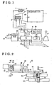
- Fig. 1 is a block view schematically illustrating an apparatus for controlling an automatic shift operation in a transmission according to an embodiment of the present invention
- Fig. 2 is a conceptual diagram illustrating an automatically shifting mechanism according to the embodiment of the present invention
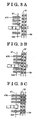
- Figs. 3A, 3B and 3C are diagrams illustrating an operation of a sleeve and a synchronizer ring according to the embodiment of the present invention
- Fig. 4 is an expansive view illustrating relevant portions of synchronizer ring teeth of the synchronizer ring and sleeve teeth of the sleeve according to the embodiment of the present invention.
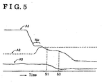
- Fig. 5 is a diagram for explaining variations of a shift stroke, a select stroke and a rotational speed of an input shaft according to the embodiment of the present invention.
- An apparatus for controlling an automatic shift operation in a transmission for a vehicle is provided for a manual transmission in which a shift stage can be switched in response to a manual operation of a shift lever by a driver.
- the apparatus for controlling an automatic shift operation in a transmission for a vehicle includes a vehicle driving-power source 1 for activating a vehicle to drive; a transmission 2 for transmitting a driving power from the driving-power source 1 to wheels of the vehicle, a driving power of a level adequate for a shift stage selected in the transmission 2; a clutch 3 to be engaged, or, as appropriate, disengaged, for transmitting, or, as appropriate, interrupting, the driving power from the driving-power source 1 to the transmission 2; a clutch actuator 4 for operating the clutch 3, an ECU 6; and an automatically shifting mechanism 8.
- the vehicle-driving power source 1 according to the embodiment of the present invention is an internal combustion engine. However, the vehicle-driving power source 1 is not limited to such an engine, and a motor can also be applied.
- the apparatus for controlling an automatic shift operation in a transmission for a vehicle further includes a shift sensor 11 for detecting a shift range over which a shift lever 10 should be positioned in accordance with an intention of a driver to shift; a select stroke sensor 13 for detecting a select-directional stroke position of the automatically shifting mechanism 8; a shift stroke sensor 14 for detecting a shift-directional stroke position of the automatically shifting mechanism 8; a steering switch 15 equipped at a driver's seat and manually operated by a driver who requires a gear ratio change in the transmission 2; a clutch sensor 16 for detecting a degree of engagement, or disengagement, of the clutch 3, or of a load applied to the clutch 3; a vehicle speed sensor 17 for detecting a vehicle speed; an acceleration opening degree sensor 19 for detecting a degree of an acceleration opening of an acceleration element such as an accelerator pedal, an acceleration element which is operated manually by a driver; a throttle opening degree sensor 20 for detecting a degree of opening of a throttle valve; and an engine rotational speed sensor 22 for detecting a
- a motor rotational speed sensor for detecting a rotational speed of the motor can be substituted for the engine rotational speed sensor 22.
- a clutch pedal does not necessarily have to be mounted at the vehicle, if needed, a clutch pedal can be mounted at a driver's seat.
- signals transmitted from the shift sensor 11, the select stroke sensor 13, the shift stroke sensor 14, the steering switch 15 and the clutch sensor 16 are respectively input to the ECU 6.
- Signals transmitted from the vehicle speed sensor 17, the acceleration opening degree sensor 19, the throttle opening degree sensor 20 and the engine rotational speed sensor 22 are input into an Engine-ECU 25, respectively, and then transmitted to the ECU 6.
- the ECU 6 accordingly outputs control signals to the automatically shifting mechanism 8 on the basis of these input signals and operates either both the automatically shifting mechanism 8 and the clutch actuator 4, or just the automatically shifting mechanism 8.
- a fully automatic system or an automatic shift system can be secured.
- the ECU 6 incorporates an input processing circuit 6a, an output processing circuit 6b, a central processing unit (abbreviated to "CPU” hereinafter) 6c and a memory storage 6d.
- the CPU 6c functions as a first processing unit 6m for implementing a first process and a second processing unit 6n for implementing a second process.
- the automatically shifting mechanism 8 has a structure built up with a driving-power source 30 equipped with a driving-power operating member 31, a synchronizer ring 32 operated for changing a gear ratio in the transmission 2, i.e., operated for changing a shift stage in the transmission 2; and a driving-power transmitting mechanism 33 positioned between the driving-power operating member 31 and the synchronizer ring 32.
- the driving-power operating member 31 of the driving-power source 30 is movable, both in a forward direction denoted by an arrow A1, and in a rearward direction denoted by an arrow A2.
- the driving-power operating member 31 is arm-shaped and is integrally provided with a first contact portion 34 and a second contact portion 35, contact portions positioned opposite one another and having a spacing therebetween.
- the first contact portion 34 is operated when the driving-power source 30 is activated for a forward operation, while the second contact portion 35 is operated when the driving-power source 30 is activated for a rearward operation.
- the driving-power transmitting mechanism 33 has a structure built up with a movable member 40, a fork shaft 45 and a sleeve 47.
- the movable member 40 includes a first engagement member 37, a speed reduction mechanism 38 and a second engagement member 39.
- the first engagement member 37 can be engaged with the driving-power operating member 31 of the driving-power source 30.
- the fork shaft 45 includes both a third engagement member 42, and a fourth engagement member 43, each of which is engageable with the second engagement member 39 of the movable member 40, and a fork 44.
- the sleeve 47 is engaged with the fork 44 of the fork shaft 45 and operates the synchronizer ring 32.
- the sleeve 47 moves the synchronizer ring 32 in a direction of a shift stage to be selected, a movement of the sleeve 47 which results in a shift operation in the transmission 2.
- the first engagement member 37 of the movable member 40 is arranged between the first contact portion 34 and the second contact portion 35 of the driving-power operating member 31.
- the transmission 2 includes an input shaft 51 with a first gear 50 mounted thereon, and an output shaft 53 with a second gear 52 mounted thereon.
- the input shaft 51 is arranged substantially in parallel to the output shaft 53.
- the driving-power operating member 31 moves in a forward direction, i.e., in the direction of arrow A1.
- the first contact portion 34 of the driving-power operating member 31 impacts on an engagement surface 37a of the first engagement portion 37, and further the driving-power operating member 31 moves the first engagement portion 37 to the extent of a predetermined stroke in the direction of arrow A1, thus maintaining the state of impact.
- the movement of the first engagement member 37 in the direction of arrow A1 can be decelerated by the speed reduction mechanism 38.
- the second engagement member 39 moves in the direction of arrow A1 and then impacts the third engagement portion 42.
- the fork shaft 45 moves, along with the fork 44, in the direction of arrow A1.
- the sleeve 47, engaged with the fork 44, then moves in the same direction, whereupon the synchronizer ring 32 moves for the purpose of selecting a shift stage in the transmission 2.
- a driving force transmitted from the vehicle driving-power source 1 to the input shaft 51 is further transmitted to the output shaft 53 via the first and second gears 50 and 52.
- the output shaft 53 then starts rotating about an axis thereof.
- the driving force is then transmitted to the wheels of a vehicle from the rotating output shaft 53, whereupon the vehicle starts moving.
- the synchronizer ring 32 is integrally provided with plural synchronizer ring teeth 320 formed on an outer surface of the synchronizer ring 32 and arranged in a circumferential direction thereof.
- the plural synchronizer ring teeth 320 are formed with a certain distance interposed between each of the adjacent teeth 320.
- the sleeve 47 i.e., an opposing member, is integrally provided with plural sleeve teeth 470, i.e., opposing teeth, formed on an inner surface of the sleeve 47 and arranged in a circumferential direction thereof.
- the plural sleeve teeth 470 are formed with a certain distance interposed between each of the adjacent teeth 470.
- the sleeve 47 serves as the opposing member of the synchronizer ring 32.
- the sleeve 47 When the sleeve 47 is operated to move in a direction for shifting, the sleeve 47 moves or advances in an axial direction thereof.
- the synchronizer ring 32 pushed by the sleeve 47, frictionally contacts with a cone surface of the first gear 50, whereupon the first gear 50 starts rotating in response to the frictional contact with the synchronizer ring 32.
- the sleeve 47 then moves or advances further in the direction for shifting, as illustrated in Fig.
- the sleeve teeth 470 of the sleeve 47 are brought into engagement with the synchronizer ring teeth 320 of the synchronizer ring 32, whereupon the synchronizer ring 32 prevents the sleeve 47 from moving further toward the synchronizer ring 32. In this way, the sleeve 47 pushes the synchronizer ring 32, resulting in rotational speeds of the sleeve 47 and the first gear 50 becoming the same, and thus ensuring synchronization.
- the sleeve 47 moves further toward the synchronizer ring 32. As illustrated in Fig. 3C , the sleeve teeth 470 of the sleeve 47 pass through the synchronizer ring teeth 320 of the synchronizer ring 32, and the sleeve teeth 470 are brought into engagement with teeth of the first gear 50, whereupon a shift operation is completed.
- a shift-up side balk point appears when a shift-up operation is performed, e.g., when a first shift stage is shifted up to a second shift stage, while a shift-down side balk point appears when a shift-down operation is performed, e.g., when the second shift stage is shifted down to the first shift stage.
- Fig. 5 represents variations of a shift stoke, a select stroke and a rotational speed of the input shaft 51, each of which is represented in the diagram by the vertical axis, over a period of time elapsed, represented by the horizontal axis.
- a characteristic line A1 in Fig. 5 represents the shift stroke, i.e., a stroke of the sleeve 47 moving from a reference position, at the time of a shift-up operation.
- a characteristic line A2 represents the select stroke, and a characteristic line A3 represents the rotational speed of the input shaft 51.
- the shift stroke varies as the shift operation proceeds.
- a Nu range illustrated by the characteristic line A1 in which the shift stroke does not substantially change, corresponds to a neutral range.
- synchronization commences at a time S1 and terminates at a time S3. Namely, synchronization is secured by the sleeve 47 and the synchronizer ring 32 during a period of time defined between the times S1 and S3.
- the rotational speed of the input shaft 51 varies to a degree which is adequate for the next shift stage to be selected. Therefore, "a balk point" is defined as a shift stroke, i.e., a position of the sleeve 47, at a time when the rotational speed of the input shaft 51 influenced by an external force of other elements varies toward a target rotational speed.
- the shift stroke of the sleeve 47 When the shift stroke of the sleeve 47 reaches a balk point during a shift operation, the rotational speed of the input shaft 51 is synchronized with that of the output shaft 53, and as a result shock may occur in response to actions of a vehicle. Moreover, if, prior to termination of synchronization, the shift stroke of the sleeve 47 progresses excessively, abnormal noise may occur as a result of clashing of gears. In order to inhibit such occurrences, the ECU 6 employs a balk point at the time of shifting.
- each of the plural synchronizer ring teeth 320 has a short synchronizer ring chamfer surface 321, i.e., a first synchronizing chamfer surface (a short one, hereinafter referred to as a short synchronizing chamfer surface) and a long synchronizer ring chamfer surface 322, i.e., a second synchronizing chamfer surface (a long one, hereinafter referred to as a long synchronizing chamfer surface), two chamfer surfaces which face one another back to back.
- a short synchronizing chamfer surface a short one, hereinafter referred to as a short synchronizing chamfer surface
- a long synchronizer ring chamfer surface i.e., a second synchronizing chamfer surface (a long one, hereinafter referred to as a long synchronizing chamfer surface)
- two chamfer surfaces which face one another back to back.
- Each of the plural synchronizer ring teeth 320 also has a short synchronizer ring side surface 325 (hereinafter referred to as a short synchronizing side surface) and a long synchronizer ring side surface 326 (hereinafter referred to as a short synchronizing side surface), two side surfaces which face one another back to back. Both the synchronizing surfaces 325 and 326 are defined along a central line Pc.
- the long synchronizing side surface 326 is adjacent to the short synchronizing chamfer surface 321, while the short synchronizing side surface 325 is adjacent to the long synchronizing chamfer surface 322.
- a spacing 32r is defined between each of the adjacent synchronizer ring teeth 320.
- each of the plural sleeve teeth 470 (i.e., opposing teeth) of the sleeve 47 (i.e., opposing member) has a short sleeve chamfer surface 471, i.e., a first opposing chamfer surface (a short one) and a long sleeve chamfer surface 472, i.e., a second opposing chamfer surface (a long one), two chamfer surfaces which face one another back to back.
- Each of the plural sleeve teeth 470 of the sleeve 47 also has a long sleeve side surface 476 and a short sleeve side surface 475, two side surfaces which face one another back to back.
- Both of the sleeve side surfaces 475 and 476 are defined along a central line Ps.
- the long sleeve side surface 476 is adjacent to the short sleeve chamfer surface 471, while the short sleeve side surface 475 is adjacent to the long sleeve chamfer surface 472.
- a spacing 47r is defined between each of the adjacent sleeve teeth 470.
- a tip angle defined between the central line Pc of each of the synchronizer ring teeth 320 and the short synchronizing chamfer surface 321 is denoted by ⁇ 1
- a tip angle defined between the central line Pc and the long synchronizing chamfer surface 322 is denoted by ⁇ 2.
- a distance defined between the central line Pc and the long synchronizing side surface 326 is denoted by L1
- a distance defined between the central line Pc and the short synchronizing side surface 325 is denoted by L2.
- a tip angle defined between the central line Ps of each of the sleeve teeth 470 and the short sleeve chamfer surface 471 is denoted by ⁇ 3, while a tip angle defined between the central line Ps and the long sleeve chamfer surface 472 is denoted by ⁇ 4.
- a distance defined between the central line Ps and the long sleeve side surface 476 is denoted by L3, while a distance defined between the central line Ps and the short sleeve side surface 475 is denoted by L4.
- a central line Pr is defined at a substantially intermediate point in the spacing 47r between the two adjacent sleeve teeth 470.
- a distance ⁇ is defined between the central line Pr and the central line Pc of each of the synchronizer ring teeth 320.
- the distance ⁇ functions as a parameter for determining a relative rotational position between the synchronizer ring 32 and the sleeve 47.
- the values denoted by ⁇ 1, ⁇ 2, ⁇ 3, ⁇ 4, L1, L2 and ⁇ are defined in an expanded view in Fig. 4
- the central lines Ps and Pc are also defined in the expanded view in Fig. 4 .
- the synchronizer ring teeth 320 approaches the sleeve teeth 470.
- the synchronizer ring teeth 320 come into contact with the sleeve teeth 470 via a surface denoted by (1) in Fig. 4 .
- the long synchronizing chamber surfaces 322 of the synchronizer ring teeth 320 come into contact with the long sleeve chamfer surfaces 472 of the sleeve teeth 470.
- the sleeve teeth 470 approaches the synchronizer ring teeth 320.
- the sleeve teeth 470 come into contact with the synchronizer ring teeth 320 via a surface denoted by (2) in Fig. 4 .
- the short sleeve chamfer surfaces 471 of the sleeve teeth 470 come into contact with the short synchronizing chamfer surfaces 321 of the synchronizer ring teeth 320.
- synchronization may be initiated at either the surface denoted by (1) and that denoted by (2), and likewise in a case of down-shifting, synchronization may be initiated at either of the two surfaces denoted by (1) and (2).
- a balk point tends to vary in accordance with relative rotational speeds, regardless of whether up-shifting or down-shifting is being performed.
- a set value C1 appropriate to a shift-up side balk point is predetermined, while a set value C2 appropriate to a shift-down side balk point is also predetermined.
- Both of these set values C1 and C2 can be stored in the memory storage 6d of the ECU 6, but can also be stored at a different portion.
- Each of the set values C1 and C2 is only calculated on the basis of a design value and can be applied as a parameter for determining an actual balk point. In other words, each of the set values C1 and C2 does not always correspond to an actual balk point.
- C1-C2 C3.
- the set values C1, C2 and by extension C3 ate predetermined on the basis of the values denoted by ⁇ 1, ⁇ 2, ⁇ 3, ⁇ 4, L1, L2 and ⁇ .
- ⁇ 1, ⁇ 2, ⁇ 3, ⁇ 4, L1, L2 and ⁇ are not substantial.
- at least one of the following conditions should be satisfied: a first condition in which a formula: ⁇ 1 ⁇ ⁇ 2 is effected, and a second condition in which a fornmla: ⁇ 3 ⁇ ⁇ 4 is effected.
- a balk point can be obtained in accordance with the following methods 1 and 2, as non-limiting examples.
- the first processing unit 6m of the ECU 6 implements a process in which a shift-up side balk point D1, which appears in response to an actual shift-up operation (e.g., from a first shift stage to a second shift stage), is actually obtained.
- the second processing unit 6n of the ECU 6 then implements a process in which a shift-down side balk point D2' is determined as a predicted value without the need for an actual shift-down operation for the purpose of obtaining the shift-down side balk point.
- the shift-down side balk point D2' is determined in accordance with one of the following formulae 1 and 2 on the basis of the shift-up side balk point D1.
- the predicted value should be denoted with a mark ['].
- D ⁇ 2 ⁇ ⁇ D ⁇ 1 - C ⁇ 3
- D ⁇ 2 ⁇ ⁇ D ⁇ 1 + C ⁇ 3
- the shift-down side balk point D2' is obtained by formula 1 when the shift operation proceeds in a positive direction within a simulated coordinate system, while it is obtained by formula 2 when the shift operation proceeds in a negative direction on a simulated coordinate system.
- the first processing unit 6m of the ECU 6 implements a process in which a shift-down balk point D2, which appears in response to an actual shift-down operation (e.g., from the second shift stage to the first shift stage), is actually obtained.
- the second processing unit 6n of the ECU 6 then implements a process in which a shift-up side balk point D1' is determined as a predicted value, without the need for an actual shift-up operation for the purpose of obtaining the shift-up side balk point.
- the shift-up side balk point D1' is determined in accordance with one of the following formulae 3 and 4 on the basis of the shift-down side balk point D2.
- D ⁇ 1 ⁇ ⁇ D ⁇ 2 - C ⁇ 3
- D ⁇ 1 ⁇ ⁇ D ⁇ 2 + C ⁇ 3
- the shift-up side balk point D1' is obtained by formula 3 when the shift operation proceeds in a negative direction within a simulated coordinate system, while it is obtained by formula 4 when the shift operation proceeds in a positive direction on a simulated coordinate system.
- a first balk point, one of the shift-up side balk point and the shift-down side balk point is initially obtained by actually performing one of a shift-up operation and a shift-down operation, and a second balk point, the other one thereof, is then determined by use of the set values C1, C2 and C3, on the basis of the first balk point.
- a second shift operation, the other one of the shift-up operation and the shift-down operation is not needed for the purpose of obtaining the second balk point, whether it be either the shift-up side balk point or the shift-down side balk point.
- a set value C4 relevant to a shift-up side balk point is predetermined, while a set value C5 relevant to a shift-down side balk point is also predetermined.
- Both of the set values C4 and C5 are stored in the memory storage 6d of the ECU 6, but they can also be stored at a different portion.
- Each of the set value C4 and C5 is calculated on the basis of the design value and can be applied as a parameter for determining an actual balk point. In other words, each of the set values C4 and C5 does not always correspond to an actual balk point.
- C4-C5 C6.
- the set values C4, C5 and C6 are predetermined on the basis of the values denoted with ⁇ 1, ⁇ 2, ⁇ 3, ⁇ 4, L1, L2 and ⁇ .
- ⁇ 1, ⁇ 2, ⁇ 3, ⁇ 4, L1, L2 and ⁇ are not substantial.
- at least one of the following conditions should be satisfied: a first condition in which a formula: ⁇ 1 ⁇ ⁇ 2 is effected, and a second condition in which a formula: ⁇ 3 ⁇ ⁇ 4 is effected.
- a balk point can be obtained in accordance with the following methods 1 and 2, as non-limiting examples, in terms of a shift operation between a second shift stage and a third shift stage.
- the first processing unit 6m of the ECU 6 implements a process in which a shift-up side balk point D3, which appears in response to an actual shift-up operation (e.g., from a second shift stage to a third shift stage), is actually obtained.
- the second processing unit 6n of the ECU 6 then implements a process in which a shift-down side balk point D4' is determined as a predicted value without the need for an actual shift-down operation for the purpose of obtaining the shift-down side balk point.
- the shift-down side balk point D4' is determined in accordance with one of the following formulae 5 and 6 on the basis of the shift-up side balk point D3.
- the predicted value should be denoted with a mark ['].
- D ⁇ 4 ⁇ ⁇ D ⁇ 3 - C ⁇ 6
- D ⁇ 4 ⁇ ⁇ D ⁇ 3 + C ⁇ 6
- the shift-down side balk point D4' is determined by formula 5 when the shift operation proceeds in a positive direction within a simulated coordinate system, and it is determined by formula 6 when the shift operation proceeds in a negative direction on a simulated coordinate system.
- the first processing unit 6m of the ECU 6 implements a process in which a shift-down balk point D4, which appears in response to an actual shift-down operation (e.g., from the third shift stage to the second shift stage), is actually obtained.
- the second processing unit 6n of the ECU 6 then implements a process in which a shift-up side balk point D3' is obtained as a predicted value without the need for an actual shift-up operation for the purpose of obtaining the shift-up side balk point.
- the shift-up side balk point D3' is determined in accordance with one of the following formulae 7 and 8 on the basis of the shift-down side balk point D4.
- D ⁇ 3 ⁇ ⁇ D ⁇ 4 - C ⁇ 3
- D ⁇ 3 ⁇ ⁇ D ⁇ 4 + C ⁇ 3
- the shift-up side balk point D3' is obtained by formula 7 when the shift operation proceeds in a negative direction within a simulated coordinate system, and it is obtained by formula 8 when the shift operation proceeds in a positive direction on a simulated coordinate system.
- a first balk point, one of the shift-up side balk point and the shift-down side balk point is initially obtained by actually performing one of a shift-up operation and a shift-down operation, and a second balk point, the other one thereof, is then determined by use of the set values C4, C5 and C6, on the basis of the first balk point.
- a second shift operation, the other one of the shift-up operation and the shift-down operation is not needed for the purpose of obtaining the second balk point, whether it be either the shift-up side balk point or the shift-down side balk point.
- the above description covers a shift operation between the second shift stage and the third shift stage, the above description can in principle be equally applied to other shift operations such as a shift operation between a third shift stage and a fourth shift stage.
- the above description can be applied for a shift operation between the fourth shift stage and a fifth shift stage.
- both of a shift-up side balk point and a shift-down side balk point can be determined for an abbreviated period of time, without the need for an actual shift down operation to accompany an actual shift up operation, or vice versa.
- the automatic shift operation controlling apparatus for a vehicle is not limited to the configuration or structure illustrated in Figs. 1 and 2 , and can be applied to other configurations or structures.
- the steering switch 15 is not indispensable for performing the embodiment of the present invention.
- the speed reduction mechanism 38 and the driving-power transmitting mechanism 33 are not limited to the structure illustrated in Fig. 2 , respectively, and other structures are possible.
Abstract
Description
- This invention generally relates to an automatic shift operation controlling apparatus for a vehicle and a method of detecting a balk point in an automatic shift operation controlling apparatus for a.vehicle.
-
JP2002-147590A EP1205691A1 ) discloses an apparatus for controlling an automatic shift operation for a vehicle, an apparatus which includes basic elements in a conventionally used manual transmission and automatically changes a shift stage in the manual transmission. This apparatus further includes a motor having a driving-power operating member, a synchronizer ring serving as a shift-operating member for switching a gear ratio in the transmission, and a driving-power transmitting mechanism positioned between the driving-power operating member of the motor and the synchronizer ring. When a shift operation takes place in the transmission, a driving power of the motor is transmitted to a sleeve, whereupon the synchronizer ring is operated in response to a movement of the sleeve. Accordingly, a rotation of the synchronizer ring is substantially synchronized with a rotation of the sleeve, and an automatic shift operation thereby achieved. - Compared with an apparatus for changing a shift stage in a transmission by a manual operation of a driver, the above-described apparatus, in which an automatic shift operation takes place, provides a much-improved level of convenience in a driving operation. With regard to the synchronizer ring in this apparatus, a plurality of synchronizer ring teeth is arranged in a circumferential direction of the synchronizer ring. With regard to the sleeve in this apparatus, a plurality of sleeve teeth (i.e., opposing teeth) is arranged in a circumferential direction of the sleeve. At the event of changing a gear ratio in the transmission, the plurality of sleeve teeth is meshed with the plurality of synchronizer ring teeth.
- A shift-up side balk point appears when a shift-up operation takes place in the transmission, while a shift-down side balk point appears when a shift-down operation takes place in the transmission. A balk point determination method is known from
US 6070117 . As far as an automatic shift operation controlling apparatus applied in a transmission is concerned, requirements have been imposed for identifying a shift-up side balk point and a shift-down side balk point. Especially, in an automatic shift operation controlling apparatus applied in a transmission, automatic operations of mechanical components take place in the transmission in order to secure a gear ratio change in the transmission. In this regard and in contrast to manual transmissions, especially for this type of automatic shift operation controlling apparatus applied in a transmission, requirements have been imposed for identifying a shift-up side balk point and a shift-down side balk point. "A balk point" could in practical terms be regarded as the same for every individual vehicle in an identical model of vehicle. However, in order to achieve an enhanced level of high precision in determining a balk point, it should be recognized that, because of several factors including dimensional tolerance, a balk point can, and often does, vary from individual vehicle to individual vehicle even within the same category of model of vehicle. - In the light of the foregoing, at a time that vehicles are delivered from factories, by actually performing a shift operation for the purpose of shifting up in a transmission, a shift-up side balk point is determined in the case of every vehicle, while by actually performing a shift operation for the purpose of shifting down in a transmission, a shift-down side balk point is determined in the case of every vehicle. The shift-up side balk point and shift-down side balk point thus determined are then stored in, for example, a memory of an automatic shift operation controlling apparatus applied in a transmission.
- However, as far as the above-described conventional method of determining the shift-up side balk point and the shift-down side balk point is concerned, actual shift operations are necessary for both shifting up and shifting down in the case of each of plural shift stages, plural shift stages which are, in general, designed into a transmission. In these circumstances, an unnecessary operation time would be taken merely on determining the shift-up side balk point and the shift-down side balk point,
- The present invention has been made in view of the above circumstances, and provides an apparatus for controlling an automatic shift operation in a transmission for a vehicle, an apparatus which is capable of curtailing to an abbreviated period the time required for determining both of an shift-up side balk point and a shift-down side balk point, and provides also a method of detecting a balk point in the apparatus for controlling an automatic shift operation in a transmission for a vehicle.
- According to an aspect of the present invention, an automatic shift operation controlling apparatus for a vehicle includes a synchronizer ring having plural synchronizer ring teeth formed on an outer surface of the synchronizer ring and arranged in a circumferential direction of the synchronizer ring, and an opposing member having plural opposing teeth formed on an inner surface of the opposing member and arranged in a circumferential direction of the opposing member, the plural opposing teeth engageable with the plural synchronizer ring teeth at a time of a change in a gear ratio in a transmission. A shift-up side balk point appears at a time of a shift-up operation, and a different shift-down side balk point appears at a time of a shift-down operation. The apparatus is characterized in comprising: a first processing unit configured to determine in actual practice a first balk point, which is one of the shift-up side balk point and the shift-down side balk point, by implementing one of the shift-up operation and the shift-down operation; and a second processing unit configured to anticipate, on a basis of the first balk point, a predicted value of a second balk point which is the other one of the shift-up side balk point and the shift-down side balk point,
- Further, each of the plural synchronizer ring teeth can include a first synchronizing chamber surface and a second synchronizing chamfer surface which face one another back to back, and each of the plural opposing member teeth includes a first opposing chamfer surface and a second opposing chamfer surface which face one another back to back. The chamfer surface can be a chamfered inclined surface.
- Still further, an angle defined between the first synchronizing chamfer surface and a central line of each of the plural synchronizer ring teeth is denoted by α1, an angle defined between the second synchronizing chamfer surface and the central line of the each of the plural synchronizer ring teeth is denoted by α2, an angle defined between the first opposing chamfer surface and a central line of each of the plural sleeve teeth is denoted by α3, and an angle defined between the second opposing chamfer surface and the central line of the each of the plural sleeve teeth is denoted by α4. In such a case, at least one of a first condition, in which α1≠α2 is effected, and a second condition, in which α3≠α4 is effected; should be satisfied. Formula α1≠α2 substantially corresponds to α1/α2 ≠ 1.0. This principle is applied to formula. α3≠α4.
- The foregoing and additional features and characteristics of the present invention will become more apparent from the following detailed description considered with reference to the accompanying drawings, wherein;
-
Fig. 1 is a block view schematically illustrating an apparatus for controlling an automatic shift operation in a transmission according to an embodiment of the present invention; -
Fig. 2 is a conceptual diagram illustrating an automatically shifting mechanism according to the embodiment of the present invention; -
Figs. 3A, 3B and 3C are diagrams illustrating an operation of a sleeve and a synchronizer ring according to the embodiment of the present invention; -
Fig. 4 is an expansive view illustrating relevant portions of synchronizer ring teeth of the synchronizer ring and sleeve teeth of the sleeve according to the embodiment of the present invention; and -
Fig. 5 is a diagram for explaining variations of a shift stroke, a select stroke and a rotational speed of an input shaft according to the embodiment of the present invention. - An embodiment of the present invention will be described in detail below with reference to the accompanying drawings. An apparatus for controlling an automatic shift operation in a transmission for a vehicle is provided for a manual transmission in which a shift stage can be switched in response to a manual operation of a shift lever by a driver.
- Referring initially to
Fig. 1 , the apparatus for controlling an automatic shift operation in a transmission for a vehicle according to the embodiment of the present invention includes a vehicle driving-power source 1 for activating a vehicle to drive; atransmission 2 for transmitting a driving power from the driving-power source 1 to wheels of the vehicle, a driving power of a level adequate for a shift stage selected in thetransmission 2; aclutch 3 to be engaged, or, as appropriate, disengaged, for transmitting, or, as appropriate, interrupting, the driving power from the driving-power source 1 to thetransmission 2; a clutch actuator 4 for operating theclutch 3, anECU 6; and an automatically shiftingmechanism 8. The vehicle-drivingpower source 1 according to the embodiment of the present invention is an internal combustion engine. However, the vehicle-drivingpower source 1 is not limited to such an engine, and a motor can also be applied. - The apparatus for controlling an automatic shift operation in a transmission for a vehicle according to the embodiment further includes a
shift sensor 11 for detecting a shift range over which ashift lever 10 should be positioned in accordance with an intention of a driver to shift; aselect stroke sensor 13 for detecting a select-directional stroke position of the automatically shiftingmechanism 8; ashift stroke sensor 14 for detecting a shift-directional stroke position of the automatically shiftingmechanism 8; a steering switch 15 equipped at a driver's seat and manually operated by a driver who requires a gear ratio change in thetransmission 2; a clutch sensor 16 for detecting a degree of engagement, or disengagement, of theclutch 3, or of a load applied to theclutch 3; avehicle speed sensor 17 for detecting a vehicle speed; an accelerationopening degree sensor 19 for detecting a degree of an acceleration opening of an acceleration element such as an accelerator pedal, an acceleration element which is operated manually by a driver; a throttleopening degree sensor 20 for detecting a degree of opening of a throttle valve; and an enginerotational speed sensor 22 for detecting a rotational speed of the engine (i.e., the vehicle driving-power source 1), i.e., for detecting a rotational speed of a crankshaft. - When a motor is applied, instead of the engine, as the vehicle driving-
power source 1, a motor rotational speed sensor for detecting a rotational speed of the motor can be substituted for the enginerotational speed sensor 22. Further, although a clutch pedal does not necessarily have to be mounted at the vehicle, if needed, a clutch pedal can be mounted at a driver's seat. - As illustrated in
Fig. 1 , signals transmitted from theshift sensor 11, theselect stroke sensor 13, theshift stroke sensor 14, the steering switch 15 and the clutch sensor 16 are respectively input to theECU 6. Signals transmitted from thevehicle speed sensor 17, the accelerationopening degree sensor 19, the throttleopening degree sensor 20 and the enginerotational speed sensor 22 are input into an Engine-ECU 25, respectively, and then transmitted to theECU 6. TheECU 6 accordingly outputs control signals to the automatically shiftingmechanism 8 on the basis of these input signals and operates either both the automatically shiftingmechanism 8 and the clutch actuator 4, or just the automatically shiftingmechanism 8. Thus, a fully automatic system or an automatic shift system can be secured. - As further illustrated in
Fig. 1 , theECU 6 incorporates an input processing circuit 6a, anoutput processing circuit 6b, a central processing unit (abbreviated to "CPU" hereinafter) 6c and amemory storage 6d. TheCPU 6c functions as afirst processing unit 6m for implementing a first process and a second processing unit 6n for implementing a second process. - Next, described below, with reference to
Fig. 2 , is the automatically shiftingmechanism 8. - The automatically shifting
mechanism 8 has a structure built up with a driving-power source 30 equipped with a driving-power operating member 31, asynchronizer ring 32 operated for changing a gear ratio in thetransmission 2, i.e., operated for changing a shift stage in thetransmission 2; and a driving-power transmitting mechanism 33 positioned between the driving-power operating member 31 and thesynchronizer ring 32. - As the driving-
power source 30 according to the embodiment of the present invention, a device such as a motor or a hydraulically driven-type device (e.g., an oil pressure device) can be applied. The driving-power operating member 31 of the driving-power source 30 is movable, both in a forward direction denoted by an arrow A1, and in a rearward direction denoted by an arrow A2. The driving-power operating member 31 is arm-shaped and is integrally provided with afirst contact portion 34 and asecond contact portion 35, contact portions positioned opposite one another and having a spacing therebetween. Thefirst contact portion 34 is operated when the driving-power source 30 is activated for a forward operation, while thesecond contact portion 35 is operated when the driving-power source 30 is activated for a rearward operation. - The driving-
power transmitting mechanism 33, as illustrated inFig. 2 , has a structure built up with amovable member 40, afork shaft 45 and asleeve 47. Themovable member 40 includes afirst engagement member 37, aspeed reduction mechanism 38 and asecond engagement member 39. Thefirst engagement member 37 can be engaged with the driving-power operating member 31 of the driving-power source 30. Thefork shaft 45 includes both athird engagement member 42, and afourth engagement member 43, each of which is engageable with thesecond engagement member 39 of themovable member 40, and afork 44. Thesleeve 47 is engaged with thefork 44 of thefork shaft 45 and operates thesynchronizer ring 32. Thesleeve 47 moves thesynchronizer ring 32 in a direction of a shift stage to be selected, a movement of thesleeve 47 which results in a shift operation in thetransmission 2. Thefirst engagement member 37 of themovable member 40 is arranged between thefirst contact portion 34 and thesecond contact portion 35 of the driving-power operating member 31. In the above description, theshift fork shaft 45, thefork 44, thesleeve 47 and thesynchronizer ring 32 have all been described in the singular in order to simplify the description. However, each of these components can be described in a multiple quantity. - Moreover, as illustrated in
Fig. 2 , thetransmission 2 includes aninput shaft 51 with afirst gear 50 mounted thereon, and anoutput shaft 53 with asecond gear 52 mounted thereon. Theinput shaft 51 is arranged substantially in parallel to theoutput shaft 53. - When the driving-
power source 30 is activated, or rotated, in one direction, the driving-power operating member 31 moves in a forward direction, i.e., in the direction of arrow A1. In this case, thefirst contact portion 34 of the driving-power operating member 31 impacts on anengagement surface 37a of thefirst engagement portion 37, and further the driving-power operating member 31 moves thefirst engagement portion 37 to the extent of a predetermined stroke in the direction of arrow A1, thus maintaining the state of impact. The movement of thefirst engagement member 37 in the direction of arrow A1 can be decelerated by thespeed reduction mechanism 38. Following the movement of thefirst engagement member 37 in the direction of arrow A1, thesecond engagement member 39 moves in the direction of arrow A1 and then impacts thethird engagement portion 42. Following the impact of thesecond engagement member 39 with thethird engagement portion 42, thefork shaft 45 moves, along with thefork 44, in the direction of arrow A1. Thesleeve 47, engaged with thefork 44, then moves in the same direction, whereupon thesynchronizer ring 32 moves for the purpose of selecting a shift stage in thetransmission 2. - When a shift stage has been selected in the
transmission 2 as described above, a driving force transmitted from the vehicle driving-power source 1 to theinput shaft 51 is further transmitted to theoutput shaft 53 via the first andsecond gears output shaft 53 then starts rotating about an axis thereof. The driving force is then transmitted to the wheels of a vehicle from therotating output shaft 53, whereupon the vehicle starts moving. - Next, a general concept of a mesh-engagement of the
synchronizer ring 32 will be described below with reference toFigs. 3A, 3B and 3C . Thesynchronizer ring 32 is integrally provided with pluralsynchronizer ring teeth 320 formed on an outer surface of thesynchronizer ring 32 and arranged in a circumferential direction thereof. The pluralsynchronizer ring teeth 320 are formed with a certain distance interposed between each of theadjacent teeth 320. Thesleeve 47, i.e., an opposing member, is integrally provided withplural sleeve teeth 470, i.e., opposing teeth, formed on an inner surface of thesleeve 47 and arranged in a circumferential direction thereof. Theplural sleeve teeth 470 are formed with a certain distance interposed between each of theadjacent teeth 470. Thesleeve 47 serves as the opposing member of thesynchronizer ring 32. - When the
sleeve 47 is operated to move in a direction for shifting, thesleeve 47 moves or advances in an axial direction thereof. Thesynchronizer ring 32, pushed by thesleeve 47, frictionally contacts with a cone surface of thefirst gear 50, whereupon thefirst gear 50 starts rotating in response to the frictional contact with thesynchronizer ring 32. When thesleeve 47 then moves or advances further in the direction for shifting, as illustrated inFig. 3B , thesleeve teeth 470 of thesleeve 47 are brought into engagement with thesynchronizer ring teeth 320 of thesynchronizer ring 32, whereupon thesynchronizer ring 32 prevents thesleeve 47 from moving further toward thesynchronizer ring 32. In this way, thesleeve 47 pushes thesynchronizer ring 32, resulting in rotational speeds of thesleeve 47 and thefirst gear 50 becoming the same, and thus ensuring synchronization. - After the synchronization has been achieved, the
sleeve 47 moves further toward thesynchronizer ring 32. As illustrated inFig. 3C , thesleeve teeth 470 of thesleeve 47 pass through thesynchronizer ring teeth 320 of thesynchronizer ring 32, and thesleeve teeth 470 are brought into engagement with teeth of thefirst gear 50, whereupon a shift operation is completed. - In the above described apparatus according to the embodiment of the present invention, a shift-up side balk point appears when a shift-up operation is performed, e.g., when a first shift stage is shifted up to a second shift stage, while a shift-down side balk point appears when a shift-down operation is performed, e.g., when the second shift stage is shifted down to the first shift stage.
-
Fig. 5 represents variations of a shift stoke, a select stroke and a rotational speed of theinput shaft 51, each of which is represented in the diagram by the vertical axis, over a period of time elapsed, represented by the horizontal axis. A characteristic line A1 inFig. 5 represents the shift stroke, i.e., a stroke of thesleeve 47 moving from a reference position, at the time of a shift-up operation. A characteristic line A2 represents the select stroke, and a characteristic line A3 represents the rotational speed of theinput shaft 51. As is evident from the characteristic line A1, the shift stroke varies as the shift operation proceeds. A Nu range illustrated by the characteristic line A1, in which the shift stroke does not substantially change, corresponds to a neutral range. - As illustrated by the characteristic line A1, synchronization commences at a time S1 and terminates at a time S3. Namely, synchronization is secured by the
sleeve 47 and thesynchronizer ring 32 during a period of time defined between the times S1 and S3. At the time S1, as illustrated by the characteristic line A3, the rotational speed of theinput shaft 51 varies to a degree which is adequate for the next shift stage to be selected. Therefore, "a balk point" is defined as a shift stroke, i.e., a position of thesleeve 47, at a time when the rotational speed of theinput shaft 51 influenced by an external force of other elements varies toward a target rotational speed. - When the shift stroke of the
sleeve 47 reaches a balk point during a shift operation, the rotational speed of theinput shaft 51 is synchronized with that of theoutput shaft 53, and as a result shock may occur in response to actions of a vehicle. Moreover, if, prior to termination of synchronization, the shift stroke of thesleeve 47 progresses excessively, abnormal noise may occur as a result of clashing of gears. In order to inhibit such occurrences, theECU 6 employs a balk point at the time of shifting. - As illustrated in
Fig. 4 , each of the pluralsynchronizer ring teeth 320 has a short synchronizerring chamfer surface 321, i.e., a first synchronizing chamfer surface (a short one, hereinafter referred to as a short synchronizing chamfer surface) and a long synchronizerring chamfer surface 322, i.e., a second synchronizing chamfer surface (a long one, hereinafter referred to as a long synchronizing chamfer surface), two chamfer surfaces which face one another back to back. Each of the pluralsynchronizer ring teeth 320 also has a short synchronizer ring side surface 325 (hereinafter referred to as a short synchronizing side surface) and a long synchronizer ring side surface 326 (hereinafter referred to as a short synchronizing side surface), two side surfaces which face one another back to back. Both the synchronizing surfaces 325 and 326 are defined along a central line Pc. The longsynchronizing side surface 326 is adjacent to the shortsynchronizing chamfer surface 321, while the shortsynchronizing side surface 325 is adjacent to the longsynchronizing chamfer surface 322. Aspacing 32r is defined between each of the adjacentsynchronizer ring teeth 320. - As further illustrated in
Fig. 4 , each of the plural sleeve teeth 470 (i.e., opposing teeth) of the sleeve 47 (i.e., opposing member) has a shortsleeve chamfer surface 471, i.e., a first opposing chamfer surface (a short one) and a longsleeve chamfer surface 472, i.e., a second opposing chamfer surface (a long one), two chamfer surfaces which face one another back to back. Each of theplural sleeve teeth 470 of thesleeve 47 also has a longsleeve side surface 476 and a shortsleeve side surface 475, two side surfaces which face one another back to back. Both of the sleeve side surfaces 475 and 476 are defined along a central line Ps. The longsleeve side surface 476 is adjacent to the shortsleeve chamfer surface 471, while the shortsleeve side surface 475 is adjacent to the longsleeve chamfer surface 472. Aspacing 47r is defined between each of theadjacent sleeve teeth 470. - As still further illustrated in
Fig. 4 , a tip angle defined between the central line Pc of each of thesynchronizer ring teeth 320 and the shortsynchronizing chamfer surface 321 is denoted byα 1, while a tip angle defined between the central line Pc and the longsynchronizing chamfer surface 322 is denoted byα 2. A distance defined between the central line Pc and the long synchronizingside surface 326 is denoted by L1, while a distance defined between the central line Pc and the shortsynchronizing side surface 325 is denoted by L2. A tip angle defined between the central line Ps of each of thesleeve teeth 470 and the shortsleeve chamfer surface 471 is denoted byα 3, while a tip angle defined between the central line Ps and the longsleeve chamfer surface 472 is denoted by α 4. A distance defined between the central line Ps and the longsleeve side surface 476 is denoted by L3, while a distance defined between the central line Ps and the shortsleeve side surface 475 is denoted by L4. Moreover, in terms of thesleeve 47, a central line Pr is defined at a substantially intermediate point in thespacing 47r between the twoadjacent sleeve teeth 470. A distance β is defined between the central line Pr and the central line Pc of each of thesynchronizer ring teeth 320. The distance β functions as a parameter for determining a relative rotational position between thesynchronizer ring 32 and thesleeve 47. Hereinafter, the values denoted byα 1,α 2,α 3, α 4, L1, L2 and β are defined in an expanded view inFig. 4 , and the central lines Ps and Pc are also defined in the expanded view inFig. 4 . - Assuming that the
synchronizer ring 32 rotates in a direction of arrow B1 inFig. 4 , when, during a time of synchronization, thesynchronizer ring 32 rotates at a faster rate than that of thesleeve 47, thesynchronizer ring teeth 320 approaches thesleeve teeth 470. In this case, thesynchronizer ring teeth 320 come into contact with thesleeve teeth 470 via a surface denoted by (1) inFig. 4 . At the surface denoted by (1), the long synchronizing chamber surfaces 322 of thesynchronizer ring teeth 320 come into contact with the long sleeve chamfer surfaces 472 of thesleeve teeth 470. - On the other hand and on the same assumption, when, during a time of synchronization, the
sleeve 47 rotates at a faster rate than that of thesynchronizer ring 32, thesleeve teeth 470 approaches thesynchronizer ring teeth 320. In this case, thesleeve teeth 470 come into contact with thesynchronizer ring teeth 320 via a surface denoted by (2) inFig. 4 . At the surface denoted with (2), the short sleeve chamfer surfaces 471 of thesleeve teeth 470 come into contact with the shortsynchronizing chamfer surfaces 321 of thesynchronizer ring teeth 320. - As described above, in consequence of the difference between the relative rotational speeds of the
synchronizer ring 32 and thesleeve 47, in the event of up-shifting, synchronization may be initiated at either the surface denoted by (1) and that denoted by (2), and likewise in a case of down-shifting, synchronization may be initiated at either of the two surfaces denoted by (1) and (2). In other words, a balk point tends to vary in accordance with relative rotational speeds, regardless of whether up-shifting or down-shifting is being performed. - In the light of the foregoing, according to the embodiment of the present invention, with reference to a design value based upon dimensions of the automatic shift operation controlling apparatus for a vehicle, a set value C1 appropriate to a shift-up side balk point is predetermined, while a set value C2 appropriate to a shift-down side balk point is also predetermined. Both of these set values C1 and C2 can be stored in the
memory storage 6d of theECU 6, but can also be stored at a different portion. Each of the set values C1 and C2 is only calculated on the basis of a design value and can be applied as a parameter for determining an actual balk point. In other words, each of the set values C1 and C2 does not always correspond to an actual balk point. Hereinafter, the following relation can be established: C1-C2=C3. - The set values C1, C2 and by extension C3 ate predetermined on the basis of the values denoted by α1,
α 2,α 3, α 4, L1, L2 and β. Experience has shown that differences in the respective set values C1, C2 and C3 among individual vehicles of an identical vehicle model are not substantial. In such an event, at least one of the following conditions should be satisfied: a first condition in which a formula:α 1 ≠α 2 is effected, and a second condition in which a fornmla:α 3 ≠ α 4 is effected. - According to the embodiment of the present invention, a balk point can be obtained in accordance with the following
methods - The
first processing unit 6m of theECU 6 implements a process in which a shift-up side balk point D1, which appears in response to an actual shift-up operation (e.g., from a first shift stage to a second shift stage), is actually obtained. The second processing unit 6n of theECU 6 then implements a process in which a shift-down side balk point D2' is determined as a predicted value without the need for an actual shift-down operation for the purpose of obtaining the shift-down side balk point. In detail, in this process, the shift-down side balk point D2' is determined in accordance with one of the followingformulae 

- The shift-down side balk point D2' is obtained by
formula 1 when the shift operation proceeds in a positive direction within a simulated coordinate system, while it is obtained byformula 2 when the shift operation proceeds in a negative direction on a simulated coordinate system. - The
first processing unit 6m of theECU 6 implements a process in which a shift-down balk point D2, which appears in response to an actual shift-down operation (e.g., from the second shift stage to the first shift stage), is actually obtained. The second processing unit 6n of theECU 6 then implements a process in which a shift-up side balk point D1' is determined as a predicted value, without the need for an actual shift-up operation for the purpose of obtaining the shift-up side balk point. In detail, in this process, the shift-up side balk point D1' is determined in accordance with one of the followingformulae 3 and 4 on the basis of the shift-down side balk point D2.

- The shift-up side balk point D1' is obtained by
formula 3 when the shift operation proceeds in a negative direction within a simulated coordinate system, while it is obtained by formula 4 when the shift operation proceeds in a positive direction on a simulated coordinate system. - As described above, according to the embodiment of the present invention, a first balk point, one of the shift-up side balk point and the shift-down side balk point, is initially obtained by actually performing one of a shift-up operation and a shift-down operation, and a second balk point, the other one thereof, is then determined by use of the set values C1, C2 and C3, on the basis of the first balk point. In this case, a second shift operation, the other one of the shift-up operation and the shift-down operation, is not needed for the purpose of obtaining the second balk point, whether it be either the shift-up side balk point or the shift-down side balk point.
- Although the above description covers a shift operation between the first shift stage and the second shift stage, the above description can in principle be equally applied to other shift operations such as a shift operation between a second shift stage and a third shift stage.
- With regard to a shift operation between the second shift stage and the third shift stage according to the embodiment of the present invention, in the same manner as described above, a set value C4 relevant to a shift-up side balk point is predetermined, while a set value C5 relevant to a shift-down side balk point is also predetermined. Both of the set values C4 and C5 are stored in the
memory storage 6d of theECU 6, but they can also be stored at a different portion. Each of the set value C4 and C5 is calculated on the basis of the design value and can be applied as a parameter for determining an actual balk point. In other words, each of the set values C4 and C5 does not always correspond to an actual balk point. Hereinafter, the following relation can be established: C4-C5=C6. - The set values C4, C5 and C6 are predetermined on the basis of the values denoted with
α 1,α 2,α 3, α 4, L1, L2 and β. Experience has shown that differences in the respective set values C1, C2 and C3 among individual vehicles of an identical vehicle model are not substantial. In such an event, at least one of the following conditions should be satisfied: a first condition in which a formula:α 1 ≠α 2 is effected, and a second condition in which a formula:α 3 ≠ α 4 is effected. - According to the embodiment of the present invention, a balk point can be obtained in accordance with the following
methods - The
first processing unit 6m of theECU 6 implements a process in which a shift-up side balk point D3, which appears in response to an actual shift-up operation (e.g., from a second shift stage to a third shift stage), is actually obtained. The second processing unit 6n of theECU 6 then implements a process in which a shift-down side balk point D4' is determined as a predicted value without the need for an actual shift-down operation for the purpose of obtaining the shift-down side balk point. In detail, in this process, the shift-down side balk point D4' is determined in accordance with one of the followingformulae 5 and 6 on the basis of the shift-up side balk point D3. The predicted value should be denoted with a mark ['].

- The shift-down side balk point D4' is determined by formula 5 when the shift operation proceeds in a positive direction within a simulated coordinate system, and it is determined by
formula 6 when the shift operation proceeds in a negative direction on a simulated coordinate system. - The
first processing unit 6m of theECU 6 implements a process in which a shift-down balk point D4, which appears in response to an actual shift-down operation (e.g., from the third shift stage to the second shift stage), is actually obtained. The second processing unit 6n of theECU 6 then implements a process in which a shift-up side balk point D3' is obtained as a predicted value without the need for an actual shift-up operation for the purpose of obtaining the shift-up side balk point. In detail, in this process, the shift-up side balk point D3' is determined in accordance with one of the followingformulae 

- The shift-up side balk point D3' is obtained by
formula 7 when the shift operation proceeds in a negative direction within a simulated coordinate system, and it is obtained byformula 8 when the shift operation proceeds in a positive direction on a simulated coordinate system. - As described above, according to the embodiment of the present invention, a first balk point, one of the shift-up side balk point and the shift-down side balk point, is initially obtained by actually performing one of a shift-up operation and a shift-down operation, and a second balk point, the other one thereof, is then determined by use of the set values C4, C5 and C6, on the basis of the first balk point. In this case, a second shift operation, the other one of the shift-up operation and the shift-down operation, is not needed for the purpose of obtaining the second balk point, whether it be either the shift-up side balk point or the shift-down side balk point.
- Although the above description covers a shift operation between the second shift stage and the third shift stage, the above description can in principle be equally applied to other shift operations such as a shift operation between a third shift stage and a fourth shift stage. When the apparatus is applied for a five-speed manual transmission, the above description can be applied for a shift operation between the fourth shift stage and a fifth shift stage.
- As described above, according to the embodiment of the present invention, at a time that vehicles are delivered from factories, both of a shift-up side balk point and a shift-down side balk point can be determined for an abbreviated period of time, without the need for an actual shift down operation to accompany an actual shift up operation, or vice versa.
- The automatic shift operation controlling apparatus for a vehicle according to the embodiment of the present invention is not limited to the configuration or structure illustrated in
Figs. 1 and 2 , and can be applied to other configurations or structures. For example, the steering switch 15 is not indispensable for performing the embodiment of the present invention. Moreover, thespeed reduction mechanism 38 and the driving-power transmitting mechanism 33 are not limited to the structure illustrated inFig. 2 , respectively, and other structures are possible.
Claims (6)
- An automatic shift operation controlling apparatus for a vehicle comprising a synchronizer ring (32) having plural synchronizer ring teeth (320) formed on an outer surface of the synchronizer ring (32) and arranged in a circumferential direction of the synchronizer ring (32), and an opposing member (47) having plural opposing teeth (470) formed on an inner surface of the opposing member (47) and arranged in a circumferential direction of the opposing member (47), the plural opposing teeth (470) engageable with the plural synchronizer ring teeth (320) at a time of a change in a gear ratio in a transmission (2), wherein a shift-up side balk point appears at a time of a shift-up operation, and a shift-down side balk point appears at a time of a shift-down operation, wherein the shift-up side balk point is different from the shift-down side balk point,
characterized in that the apparatus comprises:a first processing unit (6m) configured to determine in actual practice a first balk point, which is one of the shift-up side balk point and the shift-down side balk point, by implementing the respective shift-up operation or shift-down operation; anda second processing unit (6n) configured to anticipate, on a basis of the first balk point, a predicted value of a second balk point which is the other of the shift-up side balk point and the shift-down side balk point. - The automatic shift operation controlling apparatus for a vehicle according to claim 1, wherein each of the plural synchronizer ring teeth (320) includes a first synchronizing chamfer surface (321) and a second synchronizing chamber surface (322) which face one another back to back, and each of the plural opposing member teeth (470) includes a first opposing chamfer surface (471) and a second opposing chamfer surface (472) which face one another back to back.
- The automatic shift operation controlling apparatus for a vehicle according to claim 2, wherein an angle defined between the first synchronizing chamfer surface (321) and a central line (Pc) of each of the plural synchronizer ring teeth (320) is denoted by α1, an angle defined between the second synchronizing chamfer surface (322) and the central line (Pc) of the each of the plural synchronizer ring teeth (320) is denoted by α2, an angle defined between the first opposing chamfer surface (471) and a central line (Ps) of each of the plural sleeve teeth (470) is denoted by α3, and an angle defined between the second opposing chamfer surface (472) and the central line (Ps) of the each of the plural sleeve teeth (470) is denoted by α4, wherein at least one of a first condition, in which α1≠α2 is effected, and a second condition, in which α3≠α4 is effected, is satisfied.
- The automatic shift operation controlling apparatus for a vehicle according to any preceding claim, wherein the predicted value of the second balk point is anticipated on the basis of the first balk point and at least one set value, the at least one set value depends on at least one dimension for designing the apparatus.
- A method of detecting a balk point in an automatic shift operation controlling apparatus for a vehicle including an apparatus including a synchronizer ring (32) having plural synchronizer ring teeth (320) formed on an outer surface of the synchronizer ring (32) and arranged in a circumferential direction of the synchronizer ring (32), and an opposing member (47) having plural opposing member teeth (470) formed on an inner surface of the opposing member (47) and arranged in a circumferential direction of the opposing member (47), the plural opposing member teeth (470) engageable with the plural synchronizer ring teeth (320) at a time of a change in a gear ratio in the transmission (2), wherein a shift-up side balk point appears at a time of a shift-up operation, and a shift-down side balk point appears at a time of a shift-down operation, wherein the shift-up side balk point is different from the shift-down side balk point,
characterized in that the method comprises the steps of:determining in actual practice a first balk point, which is one of the shift-up side balk point and the shift-down side balk point, by performing the respective shift-up operation or shift-down operation; andanticipating, on a basis of the first balk point, a predicted value of a second balk point which is the other of the shift-up side balk point and the shift-down side balk point. - A method according to claim 5, wherein a first processing unit (6m) performs a first process for determining in actual practice the first balk point by implementing one of the shift-up operation and the shift-down operation, and a second processing unit (6n) performs a second process for anticipating the second balk point without a need for an other one of the shift-up operation and the shift-down operation.
Priority Applications (1)
| Application Number | Priority Date | Filing Date | Title |
|---|---|---|---|
| PL05075787T PL1584848T3 (en) | 2004-04-05 | 2005-04-05 | Automatic shift operation controlling apparatus for a vehicle and method of detecting a balk point in the same |
Applications Claiming Priority (2)
| Application Number | Priority Date | Filing Date | Title |
|---|---|---|---|
| JP2004111345 | 2004-04-05 | ||
| JP2004111345A JP4500086B2 (en) | 2004-04-05 | 2004-04-05 | Automatic transmission for vehicle and bokeh point detection method in automatic transmission for vehicle |
Publications (2)
| Publication Number | Publication Date |
|---|---|
| EP1584848A1 EP1584848A1 (en) | 2005-10-12 |
| EP1584848B1 true EP1584848B1 (en) | 2008-07-16 |
Family
ID=34909476
Family Applications (1)
| Application Number | Title | Priority Date | Filing Date |
|---|---|---|---|
| EP05075787A Not-in-force EP1584848B1 (en) | 2004-04-05 | 2005-04-05 | Automatic shift operation controlling apparatus for a vehicle and method of detecting a balk point in the same |
Country Status (5)
| Country | Link |
|---|---|
| EP (1) | EP1584848B1 (en) |
| JP (1) | JP4500086B2 (en) |
| AT (1) | ATE401516T1 (en) |
| DE (1) | DE602005008127D1 (en) |
| PL (1) | PL1584848T3 (en) |
Family Cites Families (6)
| Publication number | Priority date | Publication date | Assignee | Title |
|---|---|---|---|---|
| JPH02217629A (en) * | 1989-02-14 | 1990-08-30 | Mazda Motor Corp | Structure of syncronized engaging device |
| JPH09273571A (en) * | 1996-04-01 | 1997-10-21 | Mazda Motor Corp | Synchromesh for transmission |
| JPH1122816A (en) * | 1997-06-30 | 1999-01-26 | Aisin Seiki Co Ltd | Speed change control device for synchromesh transmission |
| JP3313327B2 (en) * | 1998-07-30 | 2002-08-12 | アイシン・エーアイ株式会社 | Shift control device for synchromesh transmission |
| JP2000329159A (en) * | 1999-05-20 | 2000-11-28 | Aisin Ai Co Ltd | Synchronizer ring |
| JP2002071016A (en) * | 2000-08-28 | 2002-03-08 | Aisin Ai Co Ltd | Gear box for synchromesh transmission |
-
2004
- 2004-04-05 JP JP2004111345A patent/JP4500086B2/en not_active Expired - Fee Related
-
2005
- 2005-04-05 AT AT05075787T patent/ATE401516T1/en not_active IP Right Cessation
- 2005-04-05 EP EP05075787A patent/EP1584848B1/en not_active Not-in-force
- 2005-04-05 DE DE602005008127T patent/DE602005008127D1/en active Active
- 2005-04-05 PL PL05075787T patent/PL1584848T3/en unknown
Also Published As
| Publication number | Publication date |
|---|---|
| PL1584848T3 (en) | 2009-04-30 |
| JP2005291475A (en) | 2005-10-20 |
| ATE401516T1 (en) | 2008-08-15 |
| DE602005008127D1 (en) | 2008-08-28 |
| EP1584848A1 (en) | 2005-10-12 |
| JP4500086B2 (en) | 2010-07-14 |
Similar Documents
| Publication | Publication Date | Title |
|---|---|---|
| KR100318246B1 (en) | Automatic mechanical shift control device and method | |
| EP1347195B1 (en) | Twin-Clutch transmission system | |
| EP2035727B8 (en) | System and method for matching engine speed to vehicle speed with a manual transmission | |
| JP5822615B2 (en) | Automatic clutch control device and shift control method thereof | |
| US9057440B2 (en) | Control unit for synchronous engaging device | |
| JPH0621646B2 (en) | Automatic mechanical transmission system | |
| EP2481956A1 (en) | Shift device for vehicle | |
| JP4701957B2 (en) | Shift end determination device | |
| JP2007113608A (en) | Speed change control device | |
| EP2481948A1 (en) | Shift device for vehicle | |
| CN113924433A (en) | Transmission and meshing clutch | |
| JP4792883B2 (en) | Control device for multiple clutch transmission | |
| EP2151609A1 (en) | Dual clutch transmission | |
| JP4616625B2 (en) | Automatic transmission control device | |
| EP1508468B1 (en) | Control apparatus and control method for a changeover gear | |
| JP6010076B2 (en) | Vehicle transmission | |
| EP1584848B1 (en) | Automatic shift operation controlling apparatus for a vehicle and method of detecting a balk point in the same | |
| JP2013087778A (en) | Dual clutch type automatic transmission and shift control method thereof | |
| EP3220015B1 (en) | Variable speed control system | |
| JP2008128438A (en) | Shift control device for transmission | |
| JP2014173681A (en) | Shift operation device of automatic transmission | |
| JP2010169210A (en) | Control device for vehicular transmission | |
| JP2010071424A (en) | Control device of transmission | |
| JP2008101643A (en) | Controller of vehicle | |
| JP6224482B2 (en) | Shifting device for automatic transmission |
Legal Events
| Date | Code | Title | Description |
|---|---|---|---|
| PUAI | Public reference made under article 153(3) epc to a published international application that has entered the european phase |
Free format text: ORIGINAL CODE: 0009012 |
|
| AK | Designated contracting states |
Kind code of ref document: A1 Designated state(s): AT BE BG CH CY CZ DE DK EE ES FI FR GB GR HU IE IS IT LI LT LU MC NL PL PT RO SE SI SK TR |
|
| AX | Request for extension of the european patent |
Extension state: AL BA HR LV MK YU |
|
| 17P | Request for examination filed |
Effective date: 20051017 |
|
| AKX | Designation fees paid |
Designated state(s): AT BE BG CH CY CZ DE DK EE ES FI FR GB GR HU IE IS IT LI LT LU MC NL PL PT RO SE SI SK TR |
|
| 17Q | First examination report despatched |
Effective date: 20061207 |
|
| GRAP | Despatch of communication of intention to grant a patent |
Free format text: ORIGINAL CODE: EPIDOSNIGR1 |
|
| GRAS | Grant fee paid |
Free format text: ORIGINAL CODE: EPIDOSNIGR3 |
|
| GRAA | (expected) grant |
Free format text: ORIGINAL CODE: 0009210 |
|
| AK | Designated contracting states |
Kind code of ref document: B1 Designated state(s): AT BE BG CH CY CZ DE DK EE ES FI FR GB GR HU IE IS IT LI LT LU MC NL PL PT RO SE SI SK TR |
|
| REG | Reference to a national code |
Ref country code: GB Ref legal event code: FG4D |
|
| REG | Reference to a national code |
Ref country code: CH Ref legal event code: EP |
|
| REF | Corresponds to: |
Ref document number: 602005008127 Country of ref document: DE Date of ref document: 20080828 Kind code of ref document: P |
|
| REG | Reference to a national code |
Ref country code: IE Ref legal event code: FG4D |
|
| NLV1 | Nl: lapsed or annulled due to failure to fulfill the requirements of art. 29p and 29m of the patents act | ||
| PG25 | Lapsed in a contracting state [announced via postgrant information from national office to epo] |
Ref country code: NL Free format text: LAPSE BECAUSE OF FAILURE TO SUBMIT A TRANSLATION OF THE DESCRIPTION OR TO PAY THE FEE WITHIN THE PRESCRIBED TIME-LIMIT Effective date: 20080716 Ref country code: IS Free format text: LAPSE BECAUSE OF FAILURE TO SUBMIT A TRANSLATION OF THE DESCRIPTION OR TO PAY THE FEE WITHIN THE PRESCRIBED TIME-LIMIT Effective date: 20081116 Ref country code: LT Free format text: LAPSE BECAUSE OF FAILURE TO SUBMIT A TRANSLATION OF THE DESCRIPTION OR TO PAY THE FEE WITHIN THE PRESCRIBED TIME-LIMIT Effective date: 20080716 |
|
| PG25 | Lapsed in a contracting state [announced via postgrant information from national office to epo] |
Ref country code: BG Free format text: LAPSE BECAUSE OF FAILURE TO SUBMIT A TRANSLATION OF THE DESCRIPTION OR TO PAY THE FEE WITHIN THE PRESCRIBED TIME-LIMIT Effective date: 20081016 Ref country code: SI Free format text: LAPSE BECAUSE OF FAILURE TO SUBMIT A TRANSLATION OF THE DESCRIPTION OR TO PAY THE FEE WITHIN THE PRESCRIBED TIME-LIMIT Effective date: 20080716 Ref country code: FI Free format text: LAPSE BECAUSE OF FAILURE TO SUBMIT A TRANSLATION OF THE DESCRIPTION OR TO PAY THE FEE WITHIN THE PRESCRIBED TIME-LIMIT Effective date: 20080716 Ref country code: PT Free format text: LAPSE BECAUSE OF FAILURE TO SUBMIT A TRANSLATION OF THE DESCRIPTION OR TO PAY THE FEE WITHIN THE PRESCRIBED TIME-LIMIT Effective date: 20081216 Ref country code: ES Free format text: LAPSE BECAUSE OF FAILURE TO SUBMIT A TRANSLATION OF THE DESCRIPTION OR TO PAY THE FEE WITHIN THE PRESCRIBED TIME-LIMIT Effective date: 20081027 Ref country code: AT Free format text: LAPSE BECAUSE OF FAILURE TO SUBMIT A TRANSLATION OF THE DESCRIPTION OR TO PAY THE FEE WITHIN THE PRESCRIBED TIME-LIMIT Effective date: 20080716 |
|
| PG25 | Lapsed in a contracting state [announced via postgrant information from national office to epo] |
Ref country code: BE Free format text: LAPSE BECAUSE OF FAILURE TO SUBMIT A TRANSLATION OF THE DESCRIPTION OR TO PAY THE FEE WITHIN THE PRESCRIBED TIME-LIMIT Effective date: 20080716 |
|
| PG25 | Lapsed in a contracting state [announced via postgrant information from national office to epo] |
Ref country code: EE Free format text: LAPSE BECAUSE OF FAILURE TO SUBMIT A TRANSLATION OF THE DESCRIPTION OR TO PAY THE FEE WITHIN THE PRESCRIBED TIME-LIMIT Effective date: 20080716 Ref country code: DK Free format text: LAPSE BECAUSE OF FAILURE TO SUBMIT A TRANSLATION OF THE DESCRIPTION OR TO PAY THE FEE WITHIN THE PRESCRIBED TIME-LIMIT Effective date: 20080716 |
|
| REG | Reference to a national code |
Ref country code: PL Ref legal event code: T3 |
|
| PLBE | No opposition filed within time limit |
Free format text: ORIGINAL CODE: 0009261 |
|
| STAA | Information on the status of an ep patent application or granted ep patent |
Free format text: STATUS: NO OPPOSITION FILED WITHIN TIME LIMIT |
|
| PG25 | Lapsed in a contracting state [announced via postgrant information from national office to epo] |
Ref country code: RO Free format text: LAPSE BECAUSE OF FAILURE TO SUBMIT A TRANSLATION OF THE DESCRIPTION OR TO PAY THE FEE WITHIN THE PRESCRIBED TIME-LIMIT Effective date: 20080716 Ref country code: SK Free format text: LAPSE BECAUSE OF FAILURE TO SUBMIT A TRANSLATION OF THE DESCRIPTION OR TO PAY THE FEE WITHIN THE PRESCRIBED TIME-LIMIT Effective date: 20080716 |
|
| 26N | No opposition filed |
Effective date: 20090417 |
|
| REG | Reference to a national code |
Ref country code: CH Ref legal event code: PL |
|
| PG25 | Lapsed in a contracting state [announced via postgrant information from national office to epo] |
Ref country code: SE Free format text: LAPSE BECAUSE OF FAILURE TO SUBMIT A TRANSLATION OF THE DESCRIPTION OR TO PAY THE FEE WITHIN THE PRESCRIBED TIME-LIMIT Effective date: 20081016 Ref country code: CH Free format text: LAPSE BECAUSE OF NON-PAYMENT OF DUE FEES Effective date: 20090430 Ref country code: LI Free format text: LAPSE BECAUSE OF NON-PAYMENT OF DUE FEES Effective date: 20090430 |
|
| REG | Reference to a national code |
Ref country code: IE Ref legal event code: MM4A |
|
| PG25 | Lapsed in a contracting state [announced via postgrant information from national office to epo] |
Ref country code: IE Free format text: LAPSE BECAUSE OF NON-PAYMENT OF DUE FEES Effective date: 20090405 Ref country code: MC Free format text: LAPSE BECAUSE OF NON-PAYMENT OF DUE FEES Effective date: 20090430 |
|
| PG25 | Lapsed in a contracting state [announced via postgrant information from national office to epo] |
Ref country code: GR Free format text: LAPSE BECAUSE OF FAILURE TO SUBMIT A TRANSLATION OF THE DESCRIPTION OR TO PAY THE FEE WITHIN THE PRESCRIBED TIME-LIMIT Effective date: 20081017 |
|
| PG25 | Lapsed in a contracting state [announced via postgrant information from national office to epo] |
Ref country code: LU Free format text: LAPSE BECAUSE OF NON-PAYMENT OF DUE FEES Effective date: 20090405 |
|
| PG25 | Lapsed in a contracting state [announced via postgrant information from national office to epo] |
Ref country code: HU Free format text: LAPSE BECAUSE OF FAILURE TO SUBMIT A TRANSLATION OF THE DESCRIPTION OR TO PAY THE FEE WITHIN THE PRESCRIBED TIME-LIMIT Effective date: 20090117 |
|
| PG25 | Lapsed in a contracting state [announced via postgrant information from national office to epo] |
Ref country code: CY Free format text: LAPSE BECAUSE OF FAILURE TO SUBMIT A TRANSLATION OF THE DESCRIPTION OR TO PAY THE FEE WITHIN THE PRESCRIBED TIME-LIMIT Effective date: 20080716 |
|
| REG | Reference to a national code |
Ref country code: FR Ref legal event code: PLFP Year of fee payment: 12 |
|
| REG | Reference to a national code |
Ref country code: DE Ref legal event code: R084 Ref document number: 602005008127 Country of ref document: DE |
|
| REG | Reference to a national code |
Ref country code: GB Ref legal event code: 746 Effective date: 20170126 |
|
| REG | Reference to a national code |
Ref country code: FR Ref legal event code: PLFP Year of fee payment: 13 |
|
| REG | Reference to a national code |
Ref country code: FR Ref legal event code: PLFP Year of fee payment: 14 |
|
| PGFP | Annual fee paid to national office [announced via postgrant information from national office to epo] |
Ref country code: CZ Payment date: 20190315 Year of fee payment: 15 Ref country code: FR Payment date: 20190313 Year of fee payment: 15 Ref country code: PL Payment date: 20190301 Year of fee payment: 15 |
|
| PGFP | Annual fee paid to national office [announced via postgrant information from national office to epo] |
Ref country code: TR Payment date: 20190327 Year of fee payment: 15 |
|
| PGFP | Annual fee paid to national office [announced via postgrant information from national office to epo] |
Ref country code: DE Payment date: 20190326 Year of fee payment: 15 Ref country code: IT Payment date: 20190419 Year of fee payment: 15 |
|
| PGFP | Annual fee paid to national office [announced via postgrant information from national office to epo] |
Ref country code: GB Payment date: 20190403 Year of fee payment: 15 |
|
| PG25 | Lapsed in a contracting state [announced via postgrant information from national office to epo] |
Ref country code: CZ Free format text: LAPSE BECAUSE OF NON-PAYMENT OF DUE FEES Effective date: 20200405 |
|
| REG | Reference to a national code |
Ref country code: DE Ref legal event code: R119 Ref document number: 602005008127 Country of ref document: DE |
|
| PG25 | Lapsed in a contracting state [announced via postgrant information from national office to epo] |
Ref country code: DE Free format text: LAPSE BECAUSE OF NON-PAYMENT OF DUE FEES Effective date: 20201103 Ref country code: FR Free format text: LAPSE BECAUSE OF NON-PAYMENT OF DUE FEES Effective date: 20200430 |
|
| GBPC | Gb: european patent ceased through non-payment of renewal fee |
Effective date: 20200405 |
|
| PG25 | Lapsed in a contracting state [announced via postgrant information from national office to epo] |
Ref country code: GB Free format text: LAPSE BECAUSE OF NON-PAYMENT OF DUE FEES Effective date: 20200405 |
|
| PG25 | Lapsed in a contracting state [announced via postgrant information from national office to epo] |
Ref country code: IT Free format text: LAPSE BECAUSE OF NON-PAYMENT OF DUE FEES Effective date: 20200405 |
|
| PG25 | Lapsed in a contracting state [announced via postgrant information from national office to epo] |
Ref country code: TR Free format text: LAPSE BECAUSE OF NON-PAYMENT OF DUE FEES Effective date: 20200405 |
|
| PG25 | Lapsed in a contracting state [announced via postgrant information from national office to epo] |
Ref country code: PL Free format text: LAPSE BECAUSE OF NON-PAYMENT OF DUE FEES Effective date: 20200405 |