EP1347195B1 - Twin-Clutch transmission system - Google Patents
Twin-Clutch transmission system Download PDFInfo
- Publication number
- EP1347195B1 EP1347195B1 EP03251540A EP03251540A EP1347195B1 EP 1347195 B1 EP1347195 B1 EP 1347195B1 EP 03251540 A EP03251540 A EP 03251540A EP 03251540 A EP03251540 A EP 03251540A EP 1347195 B1 EP1347195 B1 EP 1347195B1
- Authority
- EP
- European Patent Office
- Prior art keywords
- gear
- gear ratio
- ratio
- revolution speed
- engine revolution
- Prior art date
- Legal status (The legal status is an assumption and is not a legal conclusion. Google has not performed a legal analysis and makes no representation as to the accuracy of the status listed.)
- Expired - Lifetime
Links
- 230000005540 biological transmission Effects 0.000 title claims description 77
- 238000000034 method Methods 0.000 claims description 4
- 238000002485 combustion reaction Methods 0.000 claims description 3
- 230000007935 neutral effect Effects 0.000 description 18
- 230000003247 decreasing effect Effects 0.000 description 3
- 238000010586 diagram Methods 0.000 description 3
- 230000000284 resting effect Effects 0.000 description 3
- 238000010276 construction Methods 0.000 description 1
- 238000012986 modification Methods 0.000 description 1
- 230000004048 modification Effects 0.000 description 1
- 238000005192 partition Methods 0.000 description 1
- 230000000149 penetrating effect Effects 0.000 description 1
- 238000004904 shortening Methods 0.000 description 1
Images


Classifications
-
- B—PERFORMING OPERATIONS; TRANSPORTING
- B60—VEHICLES IN GENERAL
- B60W—CONJOINT CONTROL OF VEHICLE SUB-UNITS OF DIFFERENT TYPE OR DIFFERENT FUNCTION; CONTROL SYSTEMS SPECIALLY ADAPTED FOR HYBRID VEHICLES; ROAD VEHICLE DRIVE CONTROL SYSTEMS FOR PURPOSES NOT RELATED TO THE CONTROL OF A PARTICULAR SUB-UNIT
- B60W10/00—Conjoint control of vehicle sub-units of different type or different function
- B60W10/04—Conjoint control of vehicle sub-units of different type or different function including control of propulsion units
- B60W10/06—Conjoint control of vehicle sub-units of different type or different function including control of propulsion units including control of combustion engines
-
- B—PERFORMING OPERATIONS; TRANSPORTING
- B60—VEHICLES IN GENERAL
- B60W—CONJOINT CONTROL OF VEHICLE SUB-UNITS OF DIFFERENT TYPE OR DIFFERENT FUNCTION; CONTROL SYSTEMS SPECIALLY ADAPTED FOR HYBRID VEHICLES; ROAD VEHICLE DRIVE CONTROL SYSTEMS FOR PURPOSES NOT RELATED TO THE CONTROL OF A PARTICULAR SUB-UNIT
- B60W10/00—Conjoint control of vehicle sub-units of different type or different function
- B60W10/02—Conjoint control of vehicle sub-units of different type or different function including control of driveline clutches
-
- B—PERFORMING OPERATIONS; TRANSPORTING
- B60—VEHICLES IN GENERAL
- B60W—CONJOINT CONTROL OF VEHICLE SUB-UNITS OF DIFFERENT TYPE OR DIFFERENT FUNCTION; CONTROL SYSTEMS SPECIALLY ADAPTED FOR HYBRID VEHICLES; ROAD VEHICLE DRIVE CONTROL SYSTEMS FOR PURPOSES NOT RELATED TO THE CONTROL OF A PARTICULAR SUB-UNIT
- B60W10/00—Conjoint control of vehicle sub-units of different type or different function
- B60W10/10—Conjoint control of vehicle sub-units of different type or different function including control of change-speed gearings
- B60W10/11—Stepped gearings
- B60W10/113—Stepped gearings with two input flow paths, e.g. double clutch transmission selection of one of the torque flow paths by the corresponding input clutch
-
- B—PERFORMING OPERATIONS; TRANSPORTING
- B60—VEHICLES IN GENERAL
- B60W—CONJOINT CONTROL OF VEHICLE SUB-UNITS OF DIFFERENT TYPE OR DIFFERENT FUNCTION; CONTROL SYSTEMS SPECIALLY ADAPTED FOR HYBRID VEHICLES; ROAD VEHICLE DRIVE CONTROL SYSTEMS FOR PURPOSES NOT RELATED TO THE CONTROL OF A PARTICULAR SUB-UNIT
- B60W30/00—Purposes of road vehicle drive control systems not related to the control of a particular sub-unit, e.g. of systems using conjoint control of vehicle sub-units
- B60W30/18—Propelling the vehicle
- B60W30/1819—Propulsion control with control means using analogue circuits, relays or mechanical links
-
- F—MECHANICAL ENGINEERING; LIGHTING; HEATING; WEAPONS; BLASTING
- F16—ENGINEERING ELEMENTS AND UNITS; GENERAL MEASURES FOR PRODUCING AND MAINTAINING EFFECTIVE FUNCTIONING OF MACHINES OR INSTALLATIONS; THERMAL INSULATION IN GENERAL
- F16H—GEARING
- F16H3/00—Toothed gearings for conveying rotary motion with variable gear ratio or for reversing rotary motion
- F16H3/006—Toothed gearings for conveying rotary motion with variable gear ratio or for reversing rotary motion power being selectively transmitted by either one of the parallel flow paths
-
- F—MECHANICAL ENGINEERING; LIGHTING; HEATING; WEAPONS; BLASTING
- F16—ENGINEERING ELEMENTS AND UNITS; GENERAL MEASURES FOR PRODUCING AND MAINTAINING EFFECTIVE FUNCTIONING OF MACHINES OR INSTALLATIONS; THERMAL INSULATION IN GENERAL
- F16H—GEARING
- F16H61/00—Control functions within control units of change-speed- or reversing-gearings for conveying rotary motion ; Control of exclusively fluid gearing, friction gearing, gearings with endless flexible members or other particular types of gearing
- F16H61/68—Control functions within control units of change-speed- or reversing-gearings for conveying rotary motion ; Control of exclusively fluid gearing, friction gearing, gearings with endless flexible members or other particular types of gearing specially adapted for stepped gearings
- F16H61/684—Control functions within control units of change-speed- or reversing-gearings for conveying rotary motion ; Control of exclusively fluid gearing, friction gearing, gearings with endless flexible members or other particular types of gearing specially adapted for stepped gearings without interruption of drive
- F16H61/688—Control functions within control units of change-speed- or reversing-gearings for conveying rotary motion ; Control of exclusively fluid gearing, friction gearing, gearings with endless flexible members or other particular types of gearing specially adapted for stepped gearings without interruption of drive with two inputs, e.g. selection of one of two torque-flow paths by clutches
-
- B—PERFORMING OPERATIONS; TRANSPORTING
- B60—VEHICLES IN GENERAL
- B60W—CONJOINT CONTROL OF VEHICLE SUB-UNITS OF DIFFERENT TYPE OR DIFFERENT FUNCTION; CONTROL SYSTEMS SPECIALLY ADAPTED FOR HYBRID VEHICLES; ROAD VEHICLE DRIVE CONTROL SYSTEMS FOR PURPOSES NOT RELATED TO THE CONTROL OF A PARTICULAR SUB-UNIT
- B60W2510/00—Input parameters relating to a particular sub-units
- B60W2510/06—Combustion engines, Gas turbines
- B60W2510/0638—Engine speed
-
- B—PERFORMING OPERATIONS; TRANSPORTING
- B60—VEHICLES IN GENERAL
- B60W—CONJOINT CONTROL OF VEHICLE SUB-UNITS OF DIFFERENT TYPE OR DIFFERENT FUNCTION; CONTROL SYSTEMS SPECIALLY ADAPTED FOR HYBRID VEHICLES; ROAD VEHICLE DRIVE CONTROL SYSTEMS FOR PURPOSES NOT RELATED TO THE CONTROL OF A PARTICULAR SUB-UNIT
- B60W2540/00—Input parameters relating to occupants
- B60W2540/16—Ratio selector position
-
- F—MECHANICAL ENGINEERING; LIGHTING; HEATING; WEAPONS; BLASTING
- F16—ENGINEERING ELEMENTS AND UNITS; GENERAL MEASURES FOR PRODUCING AND MAINTAINING EFFECTIVE FUNCTIONING OF MACHINES OR INSTALLATIONS; THERMAL INSULATION IN GENERAL
- F16H—GEARING
- F16H61/00—Control functions within control units of change-speed- or reversing-gearings for conveying rotary motion ; Control of exclusively fluid gearing, friction gearing, gearings with endless flexible members or other particular types of gearing
- F16H61/02—Control functions within control units of change-speed- or reversing-gearings for conveying rotary motion ; Control of exclusively fluid gearing, friction gearing, gearings with endless flexible members or other particular types of gearing characterised by the signals used
- F16H61/0202—Control functions within control units of change-speed- or reversing-gearings for conveying rotary motion ; Control of exclusively fluid gearing, friction gearing, gearings with endless flexible members or other particular types of gearing characterised by the signals used the signals being electric
- F16H61/0204—Control functions within control units of change-speed- or reversing-gearings for conveying rotary motion ; Control of exclusively fluid gearing, friction gearing, gearings with endless flexible members or other particular types of gearing characterised by the signals used the signals being electric for gearshift control, e.g. control functions for performing shifting or generation of shift signal
- F16H61/0213—Control functions within control units of change-speed- or reversing-gearings for conveying rotary motion ; Control of exclusively fluid gearing, friction gearing, gearings with endless flexible members or other particular types of gearing characterised by the signals used the signals being electric for gearshift control, e.g. control functions for performing shifting or generation of shift signal characterised by the method for generating shift signals
- F16H2061/0216—Calculation or estimation of post shift values for different gear ratios, e.g. by using engine performance tables
-
- F—MECHANICAL ENGINEERING; LIGHTING; HEATING; WEAPONS; BLASTING
- F16—ENGINEERING ELEMENTS AND UNITS; GENERAL MEASURES FOR PRODUCING AND MAINTAINING EFFECTIVE FUNCTIONING OF MACHINES OR INSTALLATIONS; THERMAL INSULATION IN GENERAL
- F16H—GEARING
- F16H2200/00—Transmissions for multiple ratios
- F16H2200/003—Transmissions for multiple ratios characterised by the number of forward speeds
- F16H2200/0052—Transmissions for multiple ratios characterised by the number of forward speeds the gear ratios comprising six forward speeds
-
- F—MECHANICAL ENGINEERING; LIGHTING; HEATING; WEAPONS; BLASTING
- F16—ENGINEERING ELEMENTS AND UNITS; GENERAL MEASURES FOR PRODUCING AND MAINTAINING EFFECTIVE FUNCTIONING OF MACHINES OR INSTALLATIONS; THERMAL INSULATION IN GENERAL
- F16H—GEARING
- F16H2306/00—Shifting
- F16H2306/18—Preparing coupling or engaging of future gear
-
- F—MECHANICAL ENGINEERING; LIGHTING; HEATING; WEAPONS; BLASTING
- F16—ENGINEERING ELEMENTS AND UNITS; GENERAL MEASURES FOR PRODUCING AND MAINTAINING EFFECTIVE FUNCTIONING OF MACHINES OR INSTALLATIONS; THERMAL INSULATION IN GENERAL
- F16H—GEARING
- F16H63/00—Control outputs from the control unit to change-speed- or reversing-gearings for conveying rotary motion or to other devices than the final output mechanism
- F16H63/40—Control outputs from the control unit to change-speed- or reversing-gearings for conveying rotary motion or to other devices than the final output mechanism comprising signals other than signals for actuating the final output mechanisms
- F16H63/46—Signals to a clutch outside the gearbox
-
- Y—GENERAL TAGGING OF NEW TECHNOLOGICAL DEVELOPMENTS; GENERAL TAGGING OF CROSS-SECTIONAL TECHNOLOGIES SPANNING OVER SEVERAL SECTIONS OF THE IPC; TECHNICAL SUBJECTS COVERED BY FORMER USPC CROSS-REFERENCE ART COLLECTIONS [XRACs] AND DIGESTS
- Y10—TECHNICAL SUBJECTS COVERED BY FORMER USPC
- Y10T—TECHNICAL SUBJECTS COVERED BY FORMER US CLASSIFICATION
- Y10T74/00—Machine element or mechanism
- Y10T74/19—Gearing
- Y10T74/19219—Interchangeably locked
- Y10T74/19228—Multiple concentric clutch shafts
-
- Y—GENERAL TAGGING OF NEW TECHNOLOGICAL DEVELOPMENTS; GENERAL TAGGING OF CROSS-SECTIONAL TECHNOLOGIES SPANNING OVER SEVERAL SECTIONS OF THE IPC; TECHNICAL SUBJECTS COVERED BY FORMER USPC CROSS-REFERENCE ART COLLECTIONS [XRACs] AND DIGESTS
- Y10—TECHNICAL SUBJECTS COVERED BY FORMER USPC
- Y10T—TECHNICAL SUBJECTS COVERED BY FORMER US CLASSIFICATION
- Y10T74/00—Machine element or mechanism
- Y10T74/19—Gearing
- Y10T74/19219—Interchangeably locked
- Y10T74/19233—Plurality of counter shafts
-
- Y—GENERAL TAGGING OF NEW TECHNOLOGICAL DEVELOPMENTS; GENERAL TAGGING OF CROSS-SECTIONAL TECHNOLOGIES SPANNING OVER SEVERAL SECTIONS OF THE IPC; TECHNICAL SUBJECTS COVERED BY FORMER USPC CROSS-REFERENCE ART COLLECTIONS [XRACs] AND DIGESTS
- Y10—TECHNICAL SUBJECTS COVERED BY FORMER USPC
- Y10T—TECHNICAL SUBJECTS COVERED BY FORMER US CLASSIFICATION
- Y10T74/00—Machine element or mechanism
- Y10T74/19—Gearing
- Y10T74/19219—Interchangeably locked
- Y10T74/19251—Control mechanism
- Y10T74/19256—Automatic
- Y10T74/1926—Speed responsive
Definitions
- the present invention relates to a twin-clutch transmission system which comprises a first clutch for selecting a gear ratio in a first gear-ratio group and a second clutch for selecting a gear ratio in a second gear-ratio group.
- Japanese Patent Provisional Publication No. 8-320054 discloses a twin-clutch transmission which comprises two gear-ratio groups, for which clutches are provided, respectively. During when a gear ratio of one of the two gear-ratio groups is selected, the clutch for the other gear-ratio group is put in a neutral position.
- shifting is executed by the following manner:
- DE 100 36 820 A discloses a transmission system in accordance with the preamble of claim 1 and a method in accordance with the preamble of claim 6.
- the present invention provides a transmission system as set forth in claim 1.
- the invention also provides a method of controlling a twin-clutch transmission, as set forth in claim 6.
- FIGs. 1 through 6 there is shown an embodiment of a twin clutch transmission system according to the present invention.
- an input side of a gear transmission 3 is connected to an internal combustion engine E through a first clutch C1 and a second clutch C2.
- An output side of gear transmission 3 is connected to driving wheels 6 through a final ring gear 4 and a differential gear 5.
- First clutch C1 is a clutch for selecting the odd-number-speed gear-ratio group (first-speed gear, third-speed gear, and fifth-speed gear) and a reverse-speed gear from forward six speeds and one reverse-speed of gear transmission 3.
- Second clutch C2 is a clutch for selecting an even-number-speed gear-ratio group (second-speed gear, fourth-speed gear, and sixth-speed gear) from forward six gears and one reverse gear of gear transmission 3.
- Gear transmission 3 receives driving torque of engine E through one of first clutch C1 and second clutch C2, and outputs the driving torque through gears and shafts according to a selected gear ratio and through final ring gear 4 and differential gear 5 to driving wheels 6.
- a transmission control unit (TCU) 7 and an engine control unit (ECU) 8 are communicated with each other so as to bidirectionally transmit information.
- the twin-clutch transmission system comprises an input revolution speed sensor 9 acting as engine speed detecting means, a clutch position sensor 10, an output revolution speed sensor 11, a gear position sensor 12 acting as selected gear-ratio detecting means, a brake switch 13, a shift lever switch 14, a mode switch 15, a clutch actuator 16, and a shift actuator 17.
- Input revolution speed sensor 9 detects an input revolution speed of first clutch C1 when first clutch C1 is engaged, and an input revolution speed of second clutch C2 when second clutch C2 is engaged. Input revolution speed sensor 9 is coupled to transmission control unit 7 and outputs a signal indicative of the detected revolution speed to transmission control unit 7.
- Clutch position sensor 10 detects whether first clutch C1 is in an engaged state or in a disengaged state and whether second clutch C2 is in an engaged state or in a disengaged state. Clutch position sensor 10 is coupled to transmission control unit 7 and outputs a signal indicative of the states of first and second clutches C1 and C2 to transmission control unit 7.
- Output revolution speed sensor 11 detects an output revolution speed of gear transmission 3. Output revolution speed sensor 11 is coupled to transmission control unit 7 and outputs a signal indicative of the output revolution speed to transmission control unit 7.
- Gear position sensor 12 detects a selected gear position corresponding to a gear ratio selected by the operation of shift actuator 17. Gear position sensor 12 is coupled to transmission control unit 7 and outputs a signal indicative of the selected gear ratio to transmission control unit 7.
- Brake switch 13 detects whether a braking operation is being executed or not. Brake switch 13 is coupled to transmission control unit 7 and outputs a signal indicative of the braking operation to transmission control unit 7.
- Shift lever switch 14 detects an operational position of a shift lever manipulated by a driver. Shift lever switch 14 is coupled to transmission control unit 7 and outputs a signal indicative of the shift lever operation position to transmission control unit 7.
- Mode switch 15 detects a shift mode selected by the driver. Mode switch 15 is coupled to transmission control unit 7 and outputs a signal indicative of the shift mode to transmission control unit 7.
- Clutch actuator 16 is coupled to first and second clutches C1 and C2 and transmission control unit 7, and executes an engagement/disengagement control and a clutch changeover control of first and second clutches C1 and C2 on a control command outputted from transmission control unit 7.
- Shift actuator 17 is coupled to gear transmission 3 and transmission control unit 7, and controls a 1st-3rd shift fork (not shown), a 5th-R shift fork, a 2nd-4th shift fork,and a 6th shift fork, on the basis of a control command outputted from transmission control unit 7.
- an accelerator opening sensor 18 a throttle opening sensor 19 and an electrically controlled throttle unit 20 as shown in Fig. 1.
- Accelerator opening sensor 18 detects an accelerator manipulated quantity. Accelerator opening sensor 18 is coupled to engine control unit 8 and outputs a signal indicative of the accelerator manipulated quantity to engine control unit 8.
- Throttle opening sensor 18 detects an opening degree of a throttle valve of electrically control throttle unit 20 and outputs a signal indicative of the opening degree of the throttle valve to engine control unit.
- Electrically controlled throttle unit 20 is coupled to engine control unit 20, and controls the opening of the throttle value disposed in an intake-air line of engine E on the basis of a control command outputted from engine control unit 8.
- Transmission control unit 7 sends a demanded driving torque to engine control unit 8.
- Engine control unit 8 controls electrically controlled throttle unit 20 and varies the ignition timing of engine E according to the demanded driving torque to realize the demanded driving torque.
- Fig. 2 is a skeleton view showing the twin-clutch transmission system of the embodiment according to the present invention.
- Engine E is connected to first clutch C1 and second clutch C2 disposed in a clutch case 21.
- Gear transmission 3 is disposed in a transmission case 22 and connected to first and second clutches C1 and C2. Further, gear transmission 3 is connected to driving wheels 6 through final ring gear 4 and differential gear 5.
- a clutch input member 24 is commonly used by first and second clutches C1 and C2 and connected to an engine output shaft 23 of engine E. Clutch input member 24 is disposed in clutch case 21. First clutch C1 is provided between clutch input member 24 and a first clutch output member 25. Second clutch C2 is provided between clutch input member 24 and a second clutch output member 26. First clutch output member 25 is connected to a first hollow input shaft 27, which is connected to a first input shaft 31 in a manner described below. Second clutch output member 26 is connected to a second input shaft 32 which is disposed in a hollow portion of first hollow input shaft 27.
- First hollow and second input shaft 27 and 32 which are coaxially arranged, extend from clutch case 21 to transmission case 22 upon penetrating a partition wall.
- First input shaft 31 acts as a transmission input shaft when first clutch C1 is engaged and when one of the odd-number-speed gear ratios or reverse gear is selected.
- Second input shaft 32 acts as a transmission input shaft when second clutch C2 is engaged and when one of even-number-speed gears is selected.
- First and second input shafts 31 and 32 and a common output shaft 33 are arranged in parallel in transmission case 22.
- first hollow input shaft 27 The rotational driving force of first hollow input shaft 27 is transmitted to first input shaft 31 through a first input gear 34 connected to first hollow input shaft 27, a second input gear 36 connected to an idle shaft 35, and a third input gear 37 connected to input shaft 31.
- Second input gear (idle gear) 36 is engaged with first input gear 34 and third input gear 37.
- a first-speed drive gear 41, a third-speed drive gear 43, a fifth-speed drive gear 45,and a reverse drive gear 47 are rotatably connected to first input shaft 31.
- a second-speed drive gear 42, a fourth-speed drive gear 44,and a sixth-speed drive gear 46 are rotatably connected to second input gear 32.
- a first-second-speed driven gear 48, a third-fourth-speed driven gear 49, a fifth-sixth-speed driven gear 50, and a reverse driven gear 51 are fixed to or integrally formed with output shaft 33.
- a reverse idle gear 53 is fixedly connected to an idle shaft 52 and is engaged with a reverse drive gear 47 and a reverse driven gear 51.
- a 1st-3rd speed synchromesh mechanism 54 for executing a changeover among a neutral position, a 1st-speed drive gear position,and a 3rd-speed drive gear position, and a 5th-R speed synchromesh mechanism 55 for executing a changeover among a neutral position, a 5th-speed drive gear position, and a reverse drive gear position.
- 1st-3rd speed synchromesh mechanism 54 comprises a sleeve 54a engaged with a 1st-3rd speed shift fork (not shown).
- 5th-R speed synchromesh mechanism 55 comprises a sleeve 55a engaged with a 5th-R speed shift fork (not shown).
- 2nd-4th speed synchromesh mechanism 56 for executing a changeover among a neutral position, a 2nd-speed drive gear position, and a 4th-speed drive gear position
- a 6th speed synchromesh mechanism 55 for executing a changeover between a neutral position and a 6th-speed drive gear position.
- 2nd-4th speed synchromesh mechanism 56 comprises a sleeve 56a engaged with a 2nd-4th speed shift fork (not shown).
- 6th speed synchromesh mechanism 57 comprises a sleeve 57a engaged with a 6th speed shift fork (not shown).
- a final gear 58 is fixed to or integrally connected to an end portion of output shaft 33.
- Final gear 58 and final ring gear 4 are engaged with a final idle gear 50 fixedly connected to idle shaft 59.
- the rotational driving force of output shaft 33 is transmitted through final gear 58 and final idle gear 60 to final ring gear 4.
- Fig. 3A shows a fundamental engagement table of clutches C1 and C2 according to the selected gear ratio (speed gear).
- First clutch C1 is engaged when first speed is selected.
- Second clutch C2 is engaged when second speed is selected.
- First clutch C1 is engaged when third-speed gear is selected.
- Second clutch C2 is engaged when fourth speed is selected.
- First clutch C1 is engaged when fifth-speed gear is selected.
- Second clutch C2 is engaged when sixth speed is selected.
- First clutch C1 is engaged when reverse speed is selected.
- first clutch C1 is engaged when a gear ratio of the odd-number-speed gear-ratio group (including reverse speed) is selected
- second clutch C1 is engaged when a gear ratio of the even-number-speed gear-ratio group is selected. Accordingly, when upshift is sequentially executed, first and second clutches C1 and C2 are alternately engaged. Similarly, when downshift is sequentially executed, first and second clutches C1 and C2 are alternately engaged.
- a torque flow at 3rd-speed gear ratio of the odd-number speed gear-ratio group will be discussed with reference to Fig. 3B.
- first clutch C1 is engaged, and sleeve 54a of 1st-3rd speed synchromesh mechanism 54 is moved from the neutral position to a position for selecting 3rd-speed drive gear 43.
- the engine torque is transmitted in the order of engine output shaft 23 ⁇ clutch input member 24 ⁇ first clutch C1 ⁇ first clutch output member 25 ⁇ first hollow input shaft 27 ⁇ first input gear 34 ⁇ second input gear 36 ⁇ third input gear 37 ⁇ first input shaft 31. Further, the engine torque is transmitted from first input shaft 31 to final ring gear 4 through 1st-3rd speed synchromech mechanism 54, 3rd-speed drive gear 43, 3rd-4th speed driven gear 49, output shaft 33, final gear 58,and final idle gear 60 in the order of mention.
- a torque flow at 4th-speed gear ratio of the even-number-speed gear-ratio group will be discussed with reference to Fig. 3C.
- second clutch C2 is engaged, and sleeve 56a of 2nd-4th speed synchromesh mechanism 56 is moved from the neutral position to a position for selecting 4th-speed drive gear 44.
- the engine torque is transmitted in the order of engine output shaft 23 ⁇ clutch input member 24 ⁇ second clutch C2 ⁇ second input shaft 32 ⁇ 2nd-4th speed synchromech mechanism 56 ⁇ 4th-speed drive gear 44 ⁇ 3rd-4th speed driven gear 49 ⁇ output shaft 33 ⁇ final gear 58 ⁇ final idle gear 60.
- Fig. 4 is a flowchart showing pre-shift control processing executed by transmission control unit 7.
- transmission control unit 7 determines whether or not the vehicle is traveling.
- the routine proceeds to step S2.
- the routine proceeds to step S11.
- the determination as to whether the vehicle is traveling is executed by checking that the vehicle speed is not zero, that the selected shift lever position is not N, P, or R, and that at least one of first and second clutches C1 and C2 is in full engagement state.
- control unit 7 reads a present engine revolution speed.
- control unit 7 reads a present gear ratio.
- control unit 7 determines whether or not estimated engine revolution speed NextdwnN is greater than or equal to an over-revving engine revolution speed.
- the routine proceeds to step S6.
- the routine proceeds to step S8.
- the over-revving engine revolution speed represents overspeeding of engine E and is out of a normal engine revolution speed range within which engine E is operated.
- an under-revving engine revolution speed represents underspeeding of engine E and is out of the normal engine revolution speed range. If the engine revolution speed becomes the under-revving engine revolution speed, engine E will stall.
- control unit 7 executes a pre-upshift control for maintaining the obtained gear ratio by disengaging the clutch (one of first and second clutches C1 and C2) for selecting the gear-ratio group including a gear ratio obtained by upshifting from the present gear ratio and stroking a shift fork so as to select a planned upshifted gear ratio. Thereafter, the routine proceeds to step S7 to terminate the present routine.
- Step S6 functions as a pre-upshift control section of a pre-shift control means.
- control unit 7 determines whether or not estimated engine revolution speed NextupN is smaller than or equal to the over-revving engine revolution speed.
- the routine proceeds to step S10.
- the determination at step S9 is negative (Next up N > under-revving engine revolution speed)
- the routine proceeds to step S11.
- control unit 7 executes a pre-downshift control for maintaining the obtained gear ratio by disengaging the clutch (one of first and second clutches C1 and C2) for selecting the gear-ratio group including the gear ratio obtained by downshifting from the present gear ratio and stroking a shift fork so as to select a planned downshift gear ratio. Thereafter, the routine proceeds to step S7 to terminate the present routine.
- Step S10 functions as a pre-downshift control section of a pre-shift control means.
- control unit 7 terminates the present routine without executing the pre-shift control.
- step S1 When the vehicle is traveling under a low-load condition such that the vehicle speed is gradually increased although the accelerator opening is constant, the program in Fig. 3 proceeds in the order of step S1 ⁇ step S2 ⁇ step S3 ⁇ step S4, and control unit 7 calculates estimated engine revolution speed NextdwnN at a large value at step S4.
- control unit 7 calculates, at step S4, estimated engine revolution speed NextdwnN so that the estimated speed engine revolution speed NextdwnN is greater than or equal to the over-revving engine revolution speed. Accordingly, the affirmative determination is made at step S5, and the program proceeds through step S5 to step S6.
- control unit 7 executes a pre-upshift control wherein the clutch (one of first and second clutches C1 and C2) for selecting the gear ratio group including a next upshifted gear ratio is disengaged and the shift fork is stroked to select a new gear ratio achieved by the next upshift prior to the next upshift operation.
- step S1 the program in Fig. 3 proceeds from step S1 to step S8 in the order of step S1 ⁇ step S2 ⁇ steep S3 ⁇ step S4 ⁇ step S5 ⁇ step S8.
- control unit 7 calculates estimated engine revolution speed NextupN, which is the engine revolution speed if the upshift is executed under this vehicle travel condition, so as to take a small value. Thereafter, when the next downshift will be executed in near future as the vehicle speed is decreased to a limit zone of the present selected gear ratio, control unit 7 calculates estimated engine revolution speed NextupN so that the estimated engine revolution speed NextupN is smaller than or equal to the under-revving engine revolution speed at step S8. Accordingly, the affirmative determination is made at step S9, and the program proceeds through step S9 to step S10.
- control unit 7 executes a pre-downshift control wherein the clutch (one of first and second clutches C1 and C2) for selecting the gear ratio group including a next downshifted gear ratio is disengaged and the shift fork is stroked to select a new gear ratio achieved by the next downshift prior to the next downshift operation.
- this pre-downshift control this gear ratio selecting state is maintained.
- the 2nd ⁇ 3rd upshift control without the pre-upshift control is executed as follows.
- the 2nd ⁇ 3rd upshift control with the pre-upshift control according to the present invention is executed as follows.
- the shift time of the 2nd ⁇ 3rd upshift without the pre-shift control ranges from the time t1 at which the 2nd ⁇ 3rd upshift command is outputted to the time t2 at which the changeover of clutches C1 and C2 is terminated, as shown in Fig. 6.
- This shift time taken by the 2nd ⁇ 3rd upshift without the pre-shift control includes all of time periods needed for the disengagement of first clutch C1, the movement of sleeve 54a from the neutral position to the third speed position, and the changeover of clutches C1 and C2.
- the shift time thereof ranges from the time t1 at which the 2nd ⁇ 3rd upshift command is outputted to the time t2 at which the changeover of clutches C1 and C2 is terminated, as shown in Fig. 5.
- This shift time taken by the 2nd ⁇ 3rd upshift with the pre-shift control according to the present invention includes only a time period needed for the changeover of clutches C1 and C2.
- the operations denoted by 1) and 2) have been already executed by means of the pre-shift control, prior to the output of the shift command. Accordingly, the shift time of the 2nd ⁇ 3rd upshift with the pre-shift control does not include the time period needed for the disengagement of first clutch C1 and the movement of sleeve 54a from the neutral position to the third speed position.
- the present invention by checking the inexecutable shift pattern before the shifting is executed, and by executing the pre-shift control at a possible shift pattern, it becomes possible to largely shorten the shift time (shift period) as compared with that by the shift without the pre-shift control.
- This arrangement enables the shift time of the shift with pre-shift control to be generally the same as a time period for the changeover shift of a general automatic transmission.
- first and second clutches C1 and C2 a hydraulic clutch, which hydraulically controls the engagement force of the clutch, and an electromagnetic clutch, which is capable of directly controlling the engagement force of the clutch may be employed.
- a hydraulic clutch which hydraulically controls the engagement force of the clutch
- an electromagnetic clutch which is capable of directly controlling the engagement force of the clutch
Landscapes
- Engineering & Computer Science (AREA)
- Mechanical Engineering (AREA)
- Chemical & Material Sciences (AREA)
- Combustion & Propulsion (AREA)
- Transportation (AREA)
- General Engineering & Computer Science (AREA)
- Automation & Control Theory (AREA)
- Control Of Transmission Device (AREA)
Description
- The present invention relates to a twin-clutch transmission system which comprises a first clutch for selecting a gear ratio in a first gear-ratio group and a second clutch for selecting a gear ratio in a second gear-ratio group.
- Japanese Patent Provisional Publication No. 8-320054 discloses a twin-clutch transmission which comprises two gear-ratio groups, for which clutches are provided, respectively. During when a gear ratio of one of the two gear-ratio groups is selected, the clutch for the other gear-ratio group is put in a neutral position.
- In reply to a shift command generated by an operation of a shift lever, shifting is executed by the following manner:
- 1. The clutch for the gear-ratio group in a resting state is disengaged.
- 2. A desired gear ratio in the rest-state gear-ratio group is selected.
- 3. The clutch for an operating-state gear-ratio group is disengaged and the clutch for the resting-state gear-ratio group is engaged. This is so-called changeover of the clutches.
- 4. A used gear-ratio of the operating-state gear-ratio group is put in a neutral position.
- 5. After recognizing that the used gear-ratio is put in the neutral position, the clutch for the resting-state gear-ratio group is engaged.
- 6. The desired gear ratio of the resting-state gear-ratio group is put in the engaged state.
- However, this twin-clutch transmission is required to further quickly execute a shift operation.
- DE 100 36 820 A discloses a transmission system in accordance with the preamble of
claim 1 and a method in accordance with the preamble ofclaim 6. - It is an object of the present invention to provide an improved twin-clutch transmission system which is capable of shortening a shift time by employing a pre-shift control.
- The present invention provides a transmission system as set forth in
claim 1. - The invention also provides a method of controlling a twin-clutch transmission, as set forth in
claim 6. - The objects and features of this invention will become understood from the following description with reference to the accompanying drawings.
-
- Fig. 1 is a schematic view showing a transmission system of a twin-clutch transmission of an embodiment according to the present invention.
- Fig. 2 is a skeleton diagram showing the twin-clutch transmission of the embodiment.
- Fig. 3A is a fundamental engagement operation table of clutches of the twin-clutch transmission of Fig.1; Fig. 3B is a skeleton diagram showing a torque flow in the twin-clutch transmission when third gear ratio of an odd-number speed gear-ratio group is selected; and Fig. 3C is a skeleton diagram showing a torque flow in the twin-clutch transmission when fourth gear ratio of an even-number-speed gear-ratio group is selected.
- Fig. 4 is a flowchart showing a pre-shift control processing which is executed by a transmission control unit of the twin-clutch transmission of Fig. 1.
- Fig. 5 is time charts of a shift command, a shift actuator operation, and engagement/disengagement operations of both clutches during 2nd→3rd upshift with the pre-shift control.
- Fig. 6 is time charts of a shift command, a shift actuator operation,and engagement/disengagement operations of both clutches during 2nd→3rd upshift without the pre-shift control.
- Referring to Figs. 1 through 6, there is shown an embodiment of a twin clutch transmission system according to the present invention.
- As shown in Fig. 1, an input side of a
gear transmission 3 is connected to an internal combustion engine E through a first clutch C1 and a second clutch C2. An output side ofgear transmission 3 is connected to drivingwheels 6 through afinal ring gear 4 and adifferential gear 5. - First clutch C1 is a clutch for selecting the odd-number-speed gear-ratio group (first-speed gear, third-speed gear, and fifth-speed gear) and a reverse-speed gear from forward six speeds and one reverse-speed of
gear transmission 3. Second clutch C2 is a clutch for selecting an even-number-speed gear-ratio group (second-speed gear, fourth-speed gear, and sixth-speed gear) from forward six gears and one reverse gear ofgear transmission 3. -
Gear transmission 3 receives driving torque of engine E through one of first clutch C1 and second clutch C2, and outputs the driving torque through gears and shafts according to a selected gear ratio and throughfinal ring gear 4 anddifferential gear 5 to drivingwheels 6. - Referring to an electronic control system of the twin-clutch transmission system, as shown in Fig. 1, a transmission control unit (TCU) 7 and an engine control unit (ECU) 8 are communicated with each other so as to bidirectionally transmit information.
- Referring to a transmission control system, as shown in Fig. 1, the twin-clutch transmission system comprises an input
revolution speed sensor 9 acting as engine speed detecting means, aclutch position sensor 10, an outputrevolution speed sensor 11, agear position sensor 12 acting as selected gear-ratio detecting means, abrake switch 13, ashift lever switch 14, amode switch 15, aclutch actuator 16, and ashift actuator 17. - Input
revolution speed sensor 9 detects an input revolution speed of first clutch C1 when first clutch C1 is engaged, and an input revolution speed of second clutch C2 when second clutch C2 is engaged. Inputrevolution speed sensor 9 is coupled totransmission control unit 7 and outputs a signal indicative of the detected revolution speed totransmission control unit 7. -
Clutch position sensor 10 detects whether first clutch C1 is in an engaged state or in a disengaged state and whether second clutch C2 is in an engaged state or in a disengaged state.Clutch position sensor 10 is coupled totransmission control unit 7 and outputs a signal indicative of the states of first and second clutches C1 and C2 totransmission control unit 7. - Output
revolution speed sensor 11 detects an output revolution speed ofgear transmission 3. Outputrevolution speed sensor 11 is coupled totransmission control unit 7 and outputs a signal indicative of the output revolution speed totransmission control unit 7. -
Gear position sensor 12 detects a selected gear position corresponding to a gear ratio selected by the operation ofshift actuator 17.Gear position sensor 12 is coupled totransmission control unit 7 and outputs a signal indicative of the selected gear ratio totransmission control unit 7. -
Brake switch 13 detects whether a braking operation is being executed or not.Brake switch 13 is coupled totransmission control unit 7 and outputs a signal indicative of the braking operation totransmission control unit 7. - Shift
lever switch 14 detects an operational position of a shift lever manipulated by a driver.Shift lever switch 14 is coupled totransmission control unit 7 and outputs a signal indicative of the shift lever operation position totransmission control unit 7. -
Mode switch 15 detects a shift mode selected by the driver.Mode switch 15 is coupled totransmission control unit 7 and outputs a signal indicative of the shift mode totransmission control unit 7. -
Clutch actuator 16 is coupled to first and second clutches C1 and C2 andtransmission control unit 7, and executes an engagement/disengagement control and a clutch changeover control of first and second clutches C1 and C2 on a control command outputted fromtransmission control unit 7. -
Shift actuator 17 is coupled togear transmission 3 andtransmission control unit 7, and controls a 1st-3rd shift fork (not shown), a 5th-R shift fork, a 2nd-4th shift fork,and a 6th shift fork, on the basis of a control command outputted fromtransmission control unit 7. - Referring to an engine control system of the twin-clutch transmission system, there is provided an
accelerator opening sensor 18, athrottle opening sensor 19, and an electrically controlledthrottle unit 20 as shown in Fig. 1. -
Accelerator opening sensor 18 detects an accelerator manipulated quantity.Accelerator opening sensor 18 is coupled toengine control unit 8 and outputs a signal indicative of the accelerator manipulated quantity toengine control unit 8. -
Throttle opening sensor 18 detects an opening degree of a throttle valve of electrically controlthrottle unit 20 and outputs a signal indicative of the opening degree of the throttle valve to engine control unit. - Electrically controlled
throttle unit 20 is coupled toengine control unit 20, and controls the opening of the throttle value disposed in an intake-air line of engine E on the basis of a control command outputted fromengine control unit 8. -
Transmission control unit 7 sends a demanded driving torque toengine control unit 8.Engine control unit 8 controls electrically controlledthrottle unit 20 and varies the ignition timing of engine E according to the demanded driving torque to realize the demanded driving torque. - Fig. 2 is a skeleton view showing the twin-clutch transmission system of the embodiment according to the present invention.
- Engine E is connected to first clutch C1 and second clutch C2 disposed in a
clutch case 21.Gear transmission 3 is disposed in atransmission case 22 and connected to first and second clutches C1 and C2. Further,gear transmission 3 is connected to drivingwheels 6 throughfinal ring gear 4 anddifferential gear 5. - A
clutch input member 24 is commonly used by first and second clutches C1 and C2 and connected to anengine output shaft 23 of engine E.Clutch input member 24 is disposed inclutch case 21. First clutch C1 is provided betweenclutch input member 24 and a firstclutch output member 25. Second clutch C2 is provided betweenclutch input member 24 and a secondclutch output member 26. Firstclutch output member 25 is connected to a firsthollow input shaft 27, which is connected to afirst input shaft 31 in a manner described below. Secondclutch output member 26 is connected to asecond input shaft 32 which is disposed in a hollow portion of firsthollow input shaft 27. - First hollow and
second input shaft clutch case 21 totransmission case 22 upon penetrating a partition wall.First input shaft 31 acts as a transmission input shaft when first clutch C1 is engaged and when one of the odd-number-speed gear ratios or reverse gear is selected.Second input shaft 32 acts as a transmission input shaft when second clutch C2 is engaged and when one of even-number-speed gears is selected. First andsecond input shafts common output shaft 33 are arranged in parallel intransmission case 22. - The rotational driving force of first
hollow input shaft 27 is transmitted tofirst input shaft 31 through afirst input gear 34 connected to firsthollow input shaft 27, asecond input gear 36 connected to anidle shaft 35, and athird input gear 37 connected to inputshaft 31. Second input gear (idle gear) 36 is engaged withfirst input gear 34 andthird input gear 37. - A first-
speed drive gear 41, a third-speed drive gear 43, a fifth-speed drive gear 45,and areverse drive gear 47 are rotatably connected tofirst input shaft 31. A second-speed drive gear 42, a fourth-speed drive gear 44,and a sixth-speed drive gear 46 are rotatably connected tosecond input gear 32. A first-second-speed drivengear 48, a third-fourth-speed drivengear 49, a fifth-sixth-speed drivengear 50, and a reverse drivengear 51 are fixed to or integrally formed withoutput shaft 33. A reverseidle gear 53 is fixedly connected to anidle shaft 52 and is engaged with areverse drive gear 47 and a reverse drivengear 51. - Provided on
first input shaft 31 are a 1st-3rdspeed synchromesh mechanism 54 for executing a changeover among a neutral position, a 1st-speed drive gear position,and a 3rd-speed drive gear position, and a 5th-Rspeed synchromesh mechanism 55 for executing a changeover among a neutral position, a 5th-speed drive gear position, and a reverse drive gear position. 1st-3rdspeed synchromesh mechanism 54 comprises asleeve 54a engaged with a 1st-3rd speed shift fork (not shown). 5th-Rspeed synchromesh mechanism 55 comprises asleeve 55a engaged with a 5th-R speed shift fork (not shown). - Provided on
second input shaft 32 are a 2nd-4thspeed synchromesh mechanism 56 for executing a changeover among a neutral position, a 2nd-speed drive gear position, and a 4th-speed drive gear position, and a 6thspeed synchromesh mechanism 55 for executing a changeover between a neutral position and a 6th-speed drive gear position. 2nd-4thspeed synchromesh mechanism 56 comprises asleeve 56a engaged with a 2nd-4th speed shift fork (not shown). 6thspeed synchromesh mechanism 57 comprises asleeve 57a engaged with a 6th speed shift fork (not shown). - A
final gear 58 is fixed to or integrally connected to an end portion ofoutput shaft 33.Final gear 58 andfinal ring gear 4 are engaged with a finalidle gear 50 fixedly connected toidle shaft 59. The rotational driving force ofoutput shaft 33 is transmitted throughfinal gear 58 and finalidle gear 60 tofinal ring gear 4. - Subsequently, the manner of operation of the transmission of the first embodiment will be discussed hereinafter.
- Fig. 3A shows a fundamental engagement table of clutches C1 and C2 according to the selected gear ratio (speed gear). First clutch C1 is engaged when first speed is selected. Second clutch C2 is engaged when second speed is selected. First clutch C1 is engaged when third-speed gear is selected. Second clutch C2 is engaged when fourth speed is selected. First clutch C1 is engaged when fifth-speed gear is selected. Second clutch C2 is engaged when sixth speed is selected. First clutch C1 is engaged when reverse speed is selected.
- That is, first clutch C1 is engaged when a gear ratio of the odd-number-speed gear-ratio group (including reverse speed) is selected, and second clutch C1 is engaged when a gear ratio of the even-number-speed gear-ratio group is selected. Accordingly, when upshift is sequentially executed, first and second clutches C1 and C2 are alternately engaged. Similarly, when downshift is sequentially executed, first and second clutches C1 and C2 are alternately engaged.
- A torque flow at 3rd-speed gear ratio of the odd-number speed gear-ratio group will be discussed with reference to Fig. 3B. When the 3rd-speed gear ratio is selected, first clutch C1 is engaged, and
sleeve 54a of 1st-3rdspeed synchromesh mechanism 54 is moved from the neutral position to a position for selecting 3rd-speed drive gear 43. - By this selection of the 3rd-speed, the engine torque is transmitted in the order of
engine output shaft 23 →clutch input member 24 → first clutch C1 → firstclutch output member 25 → firsthollow input shaft 27 →first input gear 34 →second input gear 36 →third input gear 37 →first input shaft 31. Further, the engine torque is transmitted fromfirst input shaft 31 tofinal ring gear 4 through 1st-3rdspeed synchromech mechanism 54, 3rd-speed drive gear 43, 3rd-4th speed drivengear 49,output shaft 33,final gear 58,and finalidle gear 60 in the order of mention. - A torque flow at 4th-speed gear ratio of the even-number-speed gear-ratio group will be discussed with reference to Fig. 3C. When 4th-speed gear ratio is selected, second clutch C2 is engaged, and
sleeve 56a of 2nd-4thspeed synchromesh mechanism 56 is moved from the neutral position to a position for selecting 4th-speed drive gear 44. - By this selection of 4th-speed gear ratio, the engine torque is transmitted in the order of
engine output shaft 23 →clutch input member 24 → second clutch C2 →second input shaft 32 → 2nd-4thspeed synchromech mechanism 56 → 4th-speed drive gear 44 → 3rd-4th speed drivengear 49 →output shaft 33 →final gear 58 → finalidle gear 60. - Fig. 4 is a flowchart showing pre-shift control processing executed by
transmission control unit 7. - At step S1 in the flowchart of Fig. 4,
transmission control unit 7 determines whether or not the vehicle is traveling. When the determination at step S1 is affirmative, the routine proceeds to step S2. When the determination at step S1 is negative, the routine proceeds to step S11. The determination as to whether the vehicle is traveling is executed by checking that the vehicle speed is not zero, that the selected shift lever position is not N, P, or R, and that at least one of first and second clutches C1 and C2 is in full engagement state. - At step S2 subsequent to the execution of step S1,
control unit 7 reads a present engine revolution speed. At step S3 subsequent to the execution of step S2,control unit 7 reads a present gear ratio. - At step S4 subsequent to the execution of step S3,
control unit 7 calculates an estimated engine revolution speed NextdwnN which is an estimated engine revolution speed generated in the event that a downshift is executed from the present gear ratio to the adjacent gear ratio and the vehicle is traveling at the downshifted gear ratio. More specifically, estimated engine revolution speed NextdwnN is calculated using the present engine revolution speed, the present gear ratio, and the next gear ratio achieved by a downshift. Estimated engine revolution speed NextdwnN is obtained using the following expression. Step S4 functions as a first calculating section of an estimated engine revolution speed calculating means.
- At step
S5 control unit 7 determines whether or not estimated engine revolution speed NextdwnN is greater than or equal to an over-revving engine revolution speed. When the determination at step S5 is affirmative (NextdwnN ≥ over-revving engine revolution speed), the routine proceeds to step S6. When the determination at step S5 is negative (NextdwnN < over-revving engine revolution speed), the routine proceeds to step S8. The over-revving engine revolution speed represents overspeeding of engine E and is out of a normal engine revolution speed range within which engine E is operated. Similarly, an under-revving engine revolution speed represents underspeeding of engine E and is out of the normal engine revolution speed range. If the engine revolution speed becomes the under-revving engine revolution speed, engine E will stall. - At step
S6 control unit 7 executes a pre-upshift control for maintaining the obtained gear ratio by disengaging the clutch (one of first and second clutches C1 and C2) for selecting the gear-ratio group including a gear ratio obtained by upshifting from the present gear ratio and stroking a shift fork so as to select a planned upshifted gear ratio. Thereafter, the routine proceeds to step S7 to terminate the present routine. Step S6 functions as a pre-upshift control section of a pre-shift control means. - At step S8 subsequent to the negative determination at step S5,
control unit 8 calculates an estimated engine revolution speed NextupN which is obtained when an upshift from the present gear ratio to the adjacent gear ratio is executed and when the vehicle is traveling at the adjacent gear ratio. More specifically, estimated engine revolution speed NextupN is calculated using the present engine revolution speed, a present gear ratio, and the next gear ratio achieved by upshift. Estimated engine revolution speed NextupN is obtained using the following expression. Step S8 functions as a second calculating section of the estimated engine revolution speed calculating means.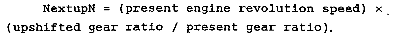
- At step
S9 control unit 7 determines whether or not estimated engine revolution speed NextupN is smaller than or equal to the over-revving engine revolution speed. When the determination at step S9 is affirmative (NextupN s under-revving engine revolution speed), the routine proceeds to step S10. When the determination at step S9 is negative (Next up N > under-revving engine revolution speed), the routine proceeds to step S11. - At step
S10 control unit 7 executes a pre-downshift control for maintaining the obtained gear ratio by disengaging the clutch (one of first and second clutches C1 and C2) for selecting the gear-ratio group including the gear ratio obtained by downshifting from the present gear ratio and stroking a shift fork so as to select a planned downshift gear ratio. Thereafter, the routine proceeds to step S7 to terminate the present routine. Step S10 functions as a pre-downshift control section of a pre-shift control means. - At step S11 subsequent to the negative determination at step S1 or the negative determination at step S9,
control unit 7 terminates the present routine without executing the pre-shift control. - When the vehicle is traveling under a low-load condition such that the vehicle speed is gradually increased although the accelerator opening is constant, the program in Fig. 3 proceeds in the order of step S1 → step S2 → step S3 → step S4, and
control unit 7 calculates estimated engine revolution speed NextdwnN at a large value at step S4. - In the event that the next upshift will be executed in near future as the vehicle speed is increased to a limit zone of the present selected gear ratio,
control unit 7 calculates, at step S4, estimated engine revolution speed NextdwnN so that the estimated speed engine revolution speed NextdwnN is greater than or equal to the over-revving engine revolution speed. Accordingly, the affirmative determination is made at step S5, and the program proceeds through step S5 to step S6. - At step S6,
control unit 7 executes a pre-upshift control wherein the clutch (one of first and second clutches C1 and C2) for selecting the gear ratio group including a next upshifted gear ratio is disengaged and the shift fork is stroked to select a new gear ratio achieved by the next upshift prior to the next upshift operation. By executing this pre-upshift control, this gear ratio selecting state is maintained. - In the event that the vehicle travels under a high-load condition in that the vehicle speed is gradually decreased although the throttle opening is kept constant, the program in Fig. 3 proceeds from step S1 to step S8 in the order of step S1 → step S2 → steep S3 → step S4 → step S5 → step S8.
- At step
S8 control unit 7 calculates estimated engine revolution speed NextupN, which is the engine revolution speed if the upshift is executed under this vehicle travel condition, so as to take a small value. Thereafter, when the next downshift will be executed in near future as the vehicle speed is decreased to a limit zone of the present selected gear ratio,control unit 7 calculates estimated engine revolution speed NextupN so that the estimated engine revolution speed NextupN is smaller than or equal to the under-revving engine revolution speed at step S8. Accordingly, the affirmative determination is made at step S9, and the program proceeds through step S9 to step S10. - At step
S10 control unit 7 executes a pre-downshift control wherein the clutch (one of first and second clutches C1 and C2) for selecting the gear ratio group including a next downshifted gear ratio is disengaged and the shift fork is stroked to select a new gear ratio achieved by the next downshift prior to the next downshift operation. By executing this pre-downshift control, this gear ratio selecting state is maintained. - Herein, there will be discussed a comparison between a shift time in 2nd→3rd upshift control with the pre-upshift control shown in Fig. 5 and 2nd→3rd upshift without the pre-upshift control shown in Fig. 6.
- As shown in Fig. 6, the 2nd→3rd upshift control without the pre-upshift control is executed as follows.
- When a 2nd→3rd upshift command is outputted according to the operation of the shift lever at time t1, the following operations are sequentially executed.
- 1) First clutch C1 for the odd-number speed gear-ratio group is disengaged. The odd-number-speed gear-ratio group is a resting gear transmission line when the second-speed gear ratio is selected.
- 2)
Sleeve 54a of 1st-3rdspeed synchromesh mechanism 54 included in the odd-number-speed gear-ratio group is moved from the neutral position to the third speed selecting position. - 3) Then, second clutch C2 for the even-number-speed gear-ratio group is disengaged and first clutch C1 for the odd-number-speed gear-ratio group is engaged. That is, a so-called changeover of clutches C1 and C2 is executed. The terminated point of this changeover of clutches C1 and C2 is defined as time t3.
- 4) After the changeover of clutches C1 and C2 is executed,
sleeve 56a of 2nd-4thspeed synchromesh mechanism 56 for selecting the second-speed is returned to the neutral position. - 5) After
sleeve 56a is returned to the neutral position, second clutch C2 for the even-number-speed gear-ratio group is engaged for the next shift. - By executing these operations, the upshift from the second speed to the third speed is completed.
- Subsequently, as shown in Fig. 5, the 2nd→3rd upshift control with the pre-upshift control according to the present invention is executed as follows.
- When estimated engine revolution speed NextdwnN becomes greater than or equal to the over-revving engine revolution speed, the following operations are sequentially executed.
- 1) At time t0 when it is determined that estimated engine revolution speed NextdwnN becomes greater than or equal to the over-revving engine revolution speed, that is, when it is determined that the downshift is not to be executed, first clutch C1 for the odd-number-speed gear-ratio group is disengaged.
- 2)
Sleeve 54a of 1st-3rdspeed synchromesh mechanism 54 included in the odd-number-speed gear-ratio group is moved from the neutral position to the third speed selecting position. - 3) When the 2nd→3rd upshift command is outputted according to the operation of the shift lever at the time t1, second clutch C2 for the even-number-speed gear-ratio group is disengaged, and first clutch C1 for the odd-number-speed gear-ratio group is engaged. That is, the changeover of clutches C1 and C2 is executed. The terminated point of this changeover of clutches C1 and C2 is denoted by time t2 in Fig. 5.
- 4) After the changeover of clutches C1 and C2 is executed,
sleeve 56a of 2nd-4thspeed synchromesh mechanism 56 for selecting the second speed is returned to the neutral position. - 5) After
sleeve 56a is returned to the neutral position, second clutch C2 for the even-number-speed gear-ratio group in the resting state is engaged for the next shift. - By executing these operations, the upshift from the second speed to the third speed is completed.
- As discussed above, the shift time of the 2nd→3rd upshift without the pre-shift control ranges from the time t1 at which the 2nd→3rd upshift command is outputted to the time t2 at which the changeover of clutches C1 and C2 is terminated, as shown in Fig. 6. This shift time taken by the 2nd→3rd upshift without the pre-shift control includes all of time periods needed for the disengagement of first clutch C1, the movement of
sleeve 54a from the neutral position to the third speed position, and the changeover of clutches C1 and C2. - In contrast to this, in case that the 2nd→3rd upshift with the pre-shift control according to the present invention is executed, the shift time thereof ranges from the time t1 at which the 2nd→3rd upshift command is outputted to the time t2 at which the changeover of clutches C1 and C2 is terminated, as shown in Fig. 5.
- This shift time taken by the 2nd→3rd upshift with the pre-shift control according to the present invention includes only a time period needed for the changeover of clutches C1 and C2. In other words, the operations denoted by 1) and 2) have been already executed by means of the pre-shift control, prior to the output of the shift command. Accordingly, the shift time of the 2nd→3rd upshift with the pre-shift control does not include the time period needed for the disengagement of first clutch C1 and the movement of
sleeve 54a from the neutral position to the third speed position. - That is, according to the present invention, by checking the inexecutable shift pattern before the shifting is executed, and by executing the pre-shift control at a possible shift pattern, it becomes possible to largely shorten the shift time (shift period) as compared with that by the shift without the pre-shift control. This arrangement enables the shift time of the shift with pre-shift control to be generally the same as a time period for the changeover shift of a general automatic transmission.
- Advantages assured by the shift control according to the present invention will be discussed hereinafter.
- (1) In the twin-clutch transmission comprising first clutch C1 for the odd-number-speed gear-ratio group and second clutch C2 for the even-number-speed gear-ratio group, an adjacent upshift gear ratio or adjacent downshift gear ratio relative to the present gear ratio is detected, and estimated engine revolution speed NextupN or NextdwnN is calculated in the case that the vehicle travels at the gear ratio of at least one of adjacent upshift gear ratio or adjacent downshift gear ratio. Further, when estimated engine revolution speed NextupN or NextdwnN is out of the normal operation engine revolution speed range,
control unit 7 determines that there is no shift to the gear ratio corresponding to the estimated engine revolution speed. According to this determination, the pre-shift control for disengaging the clutch for selecting the gear-ratio group including the other gear ratio is executed. This arrangement enables a time period needed for disengaging the clutch to be decreased and shortens the shift time of the twin-clutch transmission system according to the present invention. - (2) The shift control system according to the present invention comprises step S4 for calculating estimated engine revolution speed NextdwnN in the event that the vehicle travels at a downshifted gear ratio, and the step S8 for calculating estimated engine revolution speed NextupN in the event that the vehicle travels at a upshifted gear ratio, the step S6 for disengaging the clutch for selecting the gear ratio group including the upshifted gear ratio, and the step S10 for disengaging the clutch for selecting the gear ratio group including the downshifted gear ratio. Therefore, it becomes possible to execute the pre-shift control prior to the upshift and downshift. This shortens the time period for the upshift and the downshift of the twin-clutch transmission.
- (3) At step S6 or S10, the pre-shift control for maintaining the gear ratio selecting state is executed by disengaging the clutch for the gear ratio group including the gear ratio obtained by upshifting or downshifting the present gear ratio is disengaged, and by stroking a shift fork so as to select the next upshift gear ratio or next downshift gear ratio. Therefore, both of the time period for disengaging the clutch and the time period for moving the shift fork from the neutral position to the desired gear ratio are shortened, and the shift time is further shortened.
- Although the invention has been described above by reference to a certain embodiment of the invention, the invention is not limited to the embodiment described above. Modifications and variations of the embodiments described above will occur to those skilled in the art, in light of the above teaching. For example, as first and second clutches C1 and C2, a hydraulic clutch, which hydraulically controls the engagement force of the clutch, and an electromagnetic clutch, which is capable of directly controlling the engagement force of the clutch may be employed. Further, although the embodiment has shown and described a forward six-speed and reverse one-speed transmission, the construction of the transmission and the setting of gear ratios of the transmission are not limited by the embodiment.
- The scope of the invention is defined with reference to the following claims.
Claims (6)
- A transmission system comprising:a twin-clutch transmission (3, C1, C2) comprising
a first shaft (31) having gears for producing a first gear-ratio group,
a second shaft (32) having gears for producing a second gear-ratio group,
a first clutch (C1) being capable of connecting the first shaft (31) to an internal combustion engine (E) so as to the be selectable of one gear ratio of the first gear-ratio group,
a second clutch (C2) being capable of connecting the second shaft (32) to the engine so as to be selectable of one gear ratio of the second gear-ratio group;
an engine revolution speed detector (9) detecting an engine revolution speed;
a gear ratio detector (12) detecting a present gear ratio selected from the gear ratios of the first and second gear-ratio groups; and
a control unit (7) coupled to the transmission (3, C1, C2), the engine revolution speed detector (9), and the gear ratio detector (12), the control unit being configured
to calculate an estimated downshift engine revolution speed (NextdupN) produced in the event that a downshift-side gear ratio adjacent to the present gear ratio is selected by executing downshift, on the basis of the present engine revolution speed, the present gear ratio, and the adjacent downshift-side gear ratio, and to determine whether the estimated downshift engine revolution speed (NextdwnN) is out of a normal engine revolution speed range, and
to calculate an estimated upshift engine revolution speed (NextdwnN) produced in the event that an upshift-side gear ratio adjacent to the present gear ratio is selected by executing upshift, on the basis of the present engine revolution speed, the present gear ratio, and the adjacent upshift-side gear ratio, and to determine whether the estimated upshift engine revolution speed (NextupN) is out of the normal engine revolution speed range,
characterised in that the control unit (7) is further configured
to execute a pre-upshift control (S6) only when the estimated downshift engine revolution speed (NextdwnN) is greater than or equal to an over-revving engine revolution speed which is an upper limit of the normal operation speed range, and
to execute a pre-downshift control (S10) only when the estimated upshift engine revolution speed (NextupN) is smaller than or equal to an under-revving engine revolution speed which is a lower limit of the normal operation speed range,
wherein the pre-upshift control includes the operations of disengaging one of the first and second clutches (C1, C2), being the clutch which is engaged to select the gear-ratio group including the upshift-side gear ratio adjacent to the present gear ratio, and of selecting the appropriate upshift gear, and
wherein the pre-downshift control includes the operations of disengaging one of the first and second clutches (C1, C2), being the clutch which is engaged to select the gear-ratio group including the downshift-side gear ratio adjacent to the present gear ratio, and of selecting the appropriate downshift gear. - A transmission system as claimed in any preceding claim 1, wherein the control unit includes a transmission control unit which is communicated with an engine control unit for controlling the engine.
- A transmission system as claimed in any preceding claims 1 or 2, wherein the first gear-ratio group includes a first-speed gear ratio, a third-speed gear ratio, a fifth-speed gear ratio, and a reverse gear ratio, and the second gear-ratio group includes a second-speed gear ratio, a fourth-speed gear ratio, and a sixth-speed gear ratio.
- A transmission system as claimed in any preceding claim, wherein the twin-clutch transmission comprises a shift actuator (17) employed for selecting a desired gear ratio.
- A transmission system as claimed in any preceding claim, wherein the estimated engine revolution speed is obtained by the following expression:

- A method of controlling a twin-clutch transmission which comprises a first shaft having gears for producing a first gear-ratio group, a second shaft having gears for producing a second gear-ratio group, a first clutch (C1) being capable of connecting the first shaft to an internal combustion engine so as to be selectable of one gear ratio of the first gear-ratio group, and a second clutch (C2) being capable of connecting the second shaft to the engine so as to be selectable of one gear ratio of the second gear-ratio group, the method comprising:detecting an engine revolution speed;detecting a present gear ratio selected from the gear ratios of the first and second gear-ratio groups;calculating an estimated downshift engine revolution speed (NextdwnN) produced in the event that a downshift-side gear ratio adjacent to the present gear ratio is selected by executing downshift, on the basis of the present engine revolution speed, the present gear ratio, and the adjacent downshift-side gear ratio, and determining whether the estimated downshift engine revolution speed (NextdwnN) is out of a normal engine revolution speed range, andcalculating an estimated upshift engine revolution speed (NextdupN) produced in the event that an upshift-side gear ratio adjacent to the present gear ratio is selected by executing upshift, on the basis of the present engine revolution speed, the present gear ratio, and the adjacent upshift-side gear ratio, and determining whether the estimated upshift engine revolution speed (NextupN) is out of the normal engine revolution speed range,characterised by the further steps ofexecuting a pre-upshift control only when the estimated downshift engine revolution speed (NextdwnN) is greater than or equal to an over-revving engine revolution speed which is an upper limit of the normal operating speed range, andexecuting a pre-downshift control only when the estimated upshift engine revolution speed (NextupN) is smaller than or equal to an under-revving engine revolution speed which is a lower limit of the normal operation speed range,wherein the pre-upshift control includes the operations of disengaging one of the first and second clutches (C1, C2), being the clutch which is engaged to select the gear-ratio group including the upshift-side gear ratio adjacent to the present gear ratio, and of selecting the appropriate upshift gear, andwherein the pre-downshift control includes the operations of disengaging one of the first and second clutches (C1, C2), being the clutch which is engaged to select the gear-ratio group including the downshift-side gear ratio adjacent to the present gear ratio, and of selecting the appropriate downshift gear.
Applications Claiming Priority (2)
| Application Number | Priority Date | Filing Date | Title |
|---|---|---|---|
| JP2002075291A JP3738740B2 (en) | 2002-03-19 | 2002-03-19 | Twin clutch gear transmission |
| JP2002075291 | 2002-03-19 |
Publications (2)
| Publication Number | Publication Date |
|---|---|
| EP1347195A1 EP1347195A1 (en) | 2003-09-24 |
| EP1347195B1 true EP1347195B1 (en) | 2007-04-25 |
Family
ID=27785212
Family Applications (1)
| Application Number | Title | Priority Date | Filing Date |
|---|---|---|---|
| EP03251540A Expired - Lifetime EP1347195B1 (en) | 2002-03-19 | 2003-03-13 | Twin-Clutch transmission system |
Country Status (4)
| Country | Link |
|---|---|
| US (1) | US6679134B2 (en) |
| EP (1) | EP1347195B1 (en) |
| JP (1) | JP3738740B2 (en) |
| DE (1) | DE60313385T2 (en) |
Families Citing this family (51)
| Publication number | Priority date | Publication date | Assignee | Title |
|---|---|---|---|---|
| US4797899A (en) * | 1986-12-15 | 1989-01-10 | Maxim Integrated Products, Inc. | Integrated dual charge pump power supply including power down feature and rs-232 transmitter/receiver |
| EP1352187B1 (en) * | 2001-01-12 | 2006-08-09 | ZF Sachs AG | Method for the operation of a multiple clutching device and a power shift transmission |
| WO2002086343A1 (en) * | 2001-04-23 | 2002-10-31 | Luk Lamellen Und Kupplungsbau Beteiligungs Kg | Vehicle with an overspeed protector |
| JP3826888B2 (en) * | 2003-02-05 | 2006-09-27 | 日産自動車株式会社 | Shift control device for multi-stage automatic transmission |
| JP3952977B2 (en) * | 2003-03-19 | 2007-08-01 | 日産自動車株式会社 | Shift control device for multi-stage automatic transmission |
| JP2005325996A (en) * | 2004-04-15 | 2005-11-24 | Nissan Motor Co Ltd | Parking mechanism for vehicular meshing automatic transmission |
| JP2006029476A (en) * | 2004-07-16 | 2006-02-02 | Nissan Motor Co Ltd | Driving force transmitting device |
| DE102004039273B4 (en) * | 2004-08-13 | 2018-12-27 | Zf Friedrichshafen Ag | Dual-clutch transmission and method for controlling or regulating switching operations on a dual-clutch transmission |
| JP4492958B2 (en) * | 2005-03-31 | 2010-06-30 | 本田技研工業株式会社 | Automatic transmission |
| KR100716626B1 (en) * | 2005-08-26 | 2007-05-09 | 현대자동차주식회사 | Double Clutch Transmission control method for auto transmission car |
| JP4828929B2 (en) | 2005-12-19 | 2011-11-30 | 日立オートモティブシステムズ株式会社 | Automatic transmission control device, control method, and automatic transmission |
| JP2007198562A (en) * | 2006-01-30 | 2007-08-09 | Hitachi Ltd | Controller, control method for automatic transmission, and automatic transmission device |
| JP2007232047A (en) * | 2006-02-28 | 2007-09-13 | Hitachi Ltd | Device and method for controlling automobile |
| JP5144019B2 (en) * | 2006-03-15 | 2013-02-13 | 愛知機械工業株式会社 | Twin clutch type automatic transmission and control method thereof |
| JP4584856B2 (en) * | 2006-03-29 | 2010-11-24 | ジヤトコ株式会社 | Shift control device for automatic transmission |
| JP4640250B2 (en) * | 2006-04-27 | 2011-03-02 | 日産自動車株式会社 | Transmission control device for twin-clutch automatic manual transmission |
| US7556585B2 (en) * | 2006-06-19 | 2009-07-07 | Caterpillar Inc. | Machine drive line overspeed protection method |
| JP2008190701A (en) * | 2007-02-08 | 2008-08-21 | Hitachi Ltd | Method and device for controlling automatic transmission |
| JP5192166B2 (en) * | 2007-03-28 | 2013-05-08 | 株式会社小松製作所 | Construction vehicle |
| JP4924173B2 (en) * | 2007-04-17 | 2012-04-25 | 日産自動車株式会社 | Control device for vehicle shift |
| JP5211373B2 (en) * | 2007-05-15 | 2013-06-12 | 株式会社 神崎高級工機製作所 | Dual clutch transmission for work vehicles |
| JP2009041601A (en) | 2007-08-07 | 2009-02-26 | Hitachi Ltd | Controller and control method for automatic transmission |
| JP4941833B2 (en) | 2007-08-17 | 2012-05-30 | 株式会社 神崎高級工機製作所 | Dual clutch transmission |
| JP5251318B2 (en) * | 2007-12-05 | 2013-07-31 | 日産自動車株式会社 | Automatic manual transmission shift control device |
| DE602007005499D1 (en) | 2007-12-18 | 2010-05-06 | Fiat Ricerche | Electrohydraulic control device for a motor vehicle transmission with at least five forward gears and one reverse gear |
| FR2933759B1 (en) * | 2008-07-10 | 2011-01-14 | Renault Sas | METHOD AND DEVICE FOR CONTROLLING THE TRANSMISSION OF A MOTORPOWER GROUP OF A MOTOR VEHICLE |
| JP5232565B2 (en) * | 2008-08-04 | 2013-07-10 | アイシン・エーアイ株式会社 | Dual clutch transmission |
| JP5260227B2 (en) * | 2008-10-10 | 2013-08-14 | 日立オートモティブシステムズ株式会社 | Shift control method for automatic transmission for vehicle |
| WO2010055905A1 (en) * | 2008-11-14 | 2010-05-20 | 本田技研工業株式会社 | Transmission |
| JP4782188B2 (en) * | 2008-12-24 | 2011-09-28 | 株式会社日立ニコトランスミッション | Twin-clutch transmission for pneumatic vehicles |
| WO2010100747A1 (en) * | 2009-03-05 | 2010-09-10 | トヨタ自動車株式会社 | Shift control unit of vehicle |
| ITBO20090159A1 (en) * | 2009-03-18 | 2010-09-19 | Ferrari Spa | CONTROL METHOD FOR THE PERFORMANCE OF AN ASCENDING GEAR SHIFT IN AN AUTOMATIC MANUAL TRANSMISSION PROVIDED WITH A DOUBLE CLUTCH CHANGE |
| US8573084B2 (en) * | 2009-04-22 | 2013-11-05 | GM Global Technology Operations LLC | Dual clutch transmission |
| EP2474759B1 (en) | 2009-09-01 | 2017-04-26 | Hitachi Nico Transmission Co., Ltd. | Twin clutch type hybrid transmission |
| DE102010018532B3 (en) * | 2010-04-27 | 2011-07-07 | GETRAG FORD Transmissions GmbH, 50735 | Method for switching a dual-clutch transmission |
| EP2578901B1 (en) | 2010-06-01 | 2015-05-06 | Hitachi Nico Transmission Co., Ltd. | Twin clutch type transmission |
| JP5733022B2 (en) * | 2011-05-24 | 2015-06-10 | スズキ株式会社 | Twin clutch automatic transmission control system |
| KR101822056B1 (en) | 2011-05-31 | 2018-01-25 | 콘티넨탈 오토모티브 시스템 주식회사 | Apparatus and method for controlling transmission of dual transmintting clutch |
| KR101305842B1 (en) | 2011-06-09 | 2013-09-06 | 기아자동차주식회사 | Double Clutch Transmission Control Method for Vehicle |
| KR101316314B1 (en) * | 2011-06-09 | 2013-10-08 | 기아자동차주식회사 | Double Clutch Transmission Control Method for Vehicle |
| KR101305852B1 (en) | 2011-06-09 | 2013-09-06 | 현대자동차주식회사 | Transmission Control Method for Vehicle |
| EP2828621B1 (en) | 2012-03-23 | 2017-09-06 | Pacific Rim Engineered Products (1987) Ltd. | Gear engagement mechanism for transmissions and related methods |
| WO2013138941A1 (en) | 2012-03-23 | 2013-09-26 | Pacific Rim Engineered Products (1987) Ltd. | Dual clutch type power transmission with alternative torque transmission path providing alternative ratios |
| DE102012210512A1 (en) * | 2012-06-21 | 2013-12-24 | Zf Friedrichshafen Ag | Method for controlling a dual-clutch transmission |
| JP6278332B2 (en) * | 2013-04-22 | 2018-02-14 | スズキ株式会社 | Transmission control device |
| CN105240515B (en) * | 2015-11-17 | 2017-07-28 | 安徽江淮汽车集团股份有限公司 | A kind of wet-type dual-clutch transmission synchronization control method |
| CN106931153B (en) * | 2015-12-31 | 2018-07-17 | 上海汽车集团股份有限公司 | Gear box control unit and its shift fork pre-hung shelves method |
| JP6212581B2 (en) * | 2016-02-29 | 2017-10-11 | 本田技研工業株式会社 | Automatic transmission and control method of automatic transmission |
| US20180094723A1 (en) * | 2016-10-05 | 2018-04-05 | GM Global Technology Operations LLC | System for rationalizing measured gear ratio values in a vehicle propulsion control system |
| CN108194629B (en) * | 2017-12-18 | 2019-11-12 | 东南大学 | Internal combustion engine vehicle motor assists double clutch shifting systems and its control method |
| US11873895B2 (en) * | 2022-01-31 | 2024-01-16 | Brp-Rotax Gmbh & Co. Kg | Method for controlling a powertrain of a vehicle having a dual-clutch transmission |
Family Cites Families (18)
| Publication number | Priority date | Publication date | Assignee | Title |
|---|---|---|---|---|
| JPS58149448A (en) * | 1982-02-27 | 1983-09-05 | Toyota Motor Corp | Speed change controlling method of vehicular automatic transmission |
| GB2098679B (en) | 1982-04-27 | 1985-03-20 | Automotive Products Plc | Control system for an automatic transmission |
| JPH04282066A (en) * | 1991-03-07 | 1992-10-07 | Kawasaki Heavy Ind Ltd | Speed change control device for multistage transmission |
| GB9505174D0 (en) | 1995-03-15 | 1995-05-03 | Automotive Products Plc | Vehicle transmissions |
| JPH08320054A (en) | 1995-05-24 | 1996-12-03 | Toyota Motor Corp | Gear transmission |
| JP3446444B2 (en) * | 1996-01-24 | 2003-09-16 | トヨタ自動車株式会社 | Shift control device for automatic transmission for vehicle |
| JP3492843B2 (en) * | 1996-03-28 | 2004-02-03 | 日産ディーゼル工業株式会社 | Automatic transmission for vehicles |
| JPH09317864A (en) * | 1996-05-27 | 1997-12-12 | Toyota Motor Corp | Automatic transmission controller |
| DE19711820A1 (en) | 1996-08-08 | 1998-09-24 | Volkswagen Ag | Method for shifting a double clutch transmission and double clutch transmission |
| DE19631983C1 (en) | 1996-08-08 | 1998-02-12 | Volkswagen Ag | Method for shifting a double clutch transmission and double clutch transmission with synchronizing device |
| JPH10299884A (en) | 1997-04-25 | 1998-11-13 | Toyota Motor Corp | Controller for twin clutch type gear transmission |
| JPH10318361A (en) * | 1997-05-21 | 1998-12-04 | Toyota Motor Corp | Shift control device for twin clutch type automatic transmission |
| JP3570192B2 (en) * | 1998-01-13 | 2004-09-29 | トヨタ自動車株式会社 | Automatic transmission jump downshift control device |
| DE10036820A1 (en) | 1999-08-10 | 2002-02-07 | Daimler Chrysler Ag | Dual coupling multi-gear drive has controller predicting future gear change and/or gear ratio for at least some regions of operation taking into account parameter characteristic driving mode |
| DE19939818C1 (en) * | 1999-08-21 | 2001-01-25 | Daimler Chrysler Ag | Automobile drive transmission control method uses 2 parallel clutches controlled via electronic drive control during gear changing |
| JP4663840B2 (en) * | 2000-03-03 | 2011-04-06 | いすゞ自動車株式会社 | Engine overrun prevention device for automatic transmission |
| US6427550B1 (en) * | 2001-01-12 | 2002-08-06 | New Venture Gear, Inc. | Twin clutch automated transaxle |
| US6463821B1 (en) * | 2001-06-29 | 2002-10-15 | Daimlerchrysler Corporation | Method of controlling a transmission having a dual clutch system |
-
2002
- 2002-03-19 JP JP2002075291A patent/JP3738740B2/en not_active Expired - Fee Related
-
2003
- 2003-03-06 US US10/379,797 patent/US6679134B2/en not_active Expired - Fee Related
- 2003-03-13 EP EP03251540A patent/EP1347195B1/en not_active Expired - Lifetime
- 2003-03-13 DE DE60313385T patent/DE60313385T2/en not_active Expired - Lifetime
Also Published As
| Publication number | Publication date |
|---|---|
| US20030178278A1 (en) | 2003-09-25 |
| DE60313385D1 (en) | 2007-06-06 |
| EP1347195A1 (en) | 2003-09-24 |
| JP3738740B2 (en) | 2006-01-25 |
| US6679134B2 (en) | 2004-01-20 |
| DE60313385T2 (en) | 2008-01-03 |
| JP2003269592A (en) | 2003-09-25 |
Similar Documents
| Publication | Publication Date | Title |
|---|---|---|
| EP1347195B1 (en) | Twin-Clutch transmission system | |
| EP2065623B1 (en) | Vehicle shift control apparatus | |
| JP4432984B2 (en) | Control device for automatic transmission | |
| US7384374B2 (en) | Tip-in/tip-out gear shift control for a powershift automatic transmission | |
| US8340877B2 (en) | Engine speed synchronizer and engine speed synchronization method for manual transmission with engine clutch | |
| JP5485370B2 (en) | Control device for automatic transmission | |
| EP1460317A2 (en) | Automatic shift control apparatus and method for manual transmission | |
| US6547698B2 (en) | Control system for automatic vehicle transmissions | |
| EP2063151B1 (en) | Abnormal-period automatic shift control apparatus of automated manual transmission | |
| EP0300792B1 (en) | Automatic change gear control means | |
| JPH10318361A (en) | Shift control device for twin clutch type automatic transmission | |
| JPH0492159A (en) | Speed change control device of automatic transmission | |
| JP5962778B2 (en) | Automatic transmission starting clutch control device | |
| JP2006132562A (en) | Shift control device in clutch one-sided wear for twin clutch type manual transmission | |
| JP2004293737A (en) | Control device and control method for automobile | |
| JP2006132574A (en) | Shift control device in failure of twin clutch manual transmission | |
| JP5512336B2 (en) | Control device for automatic transmission | |
| JP4007321B2 (en) | Automotive control device | |
| WO2003033290A1 (en) | Control apparatus and control method for a changeover gear | |
| KR0162511B1 (en) | Control apparatus for hydraulically operated vehicular transmission | |
| JPH08159266A (en) | Gear shift oil pressure control device for automatic transmission | |
| JP2005180628A (en) | Automatic gear shifting controller for manual transmission | |
| JPH07259975A (en) | Speed change control device for automatic transmission | |
| JP3223232B2 (en) | Control device for automatic transmission for vehicles | |
| JP2003336736A (en) | Automatic transmission for vehicle |
Legal Events
| Date | Code | Title | Description |
|---|---|---|---|
| PUAI | Public reference made under article 153(3) epc to a published international application that has entered the european phase |
Free format text: ORIGINAL CODE: 0009012 |
|
| 17P | Request for examination filed |
Effective date: 20030411 |
|
| AK | Designated contracting states |
Kind code of ref document: A1 Designated state(s): AT BE BG CH CY CZ DE DK EE ES FI FR GB GR HU IE IT LI LU MC NL PT RO SE SI SK TR |
|
| AX | Request for extension of the european patent |
Extension state: AL LT LV MK |
|
| 17Q | First examination report despatched |
Effective date: 20040402 |
|
| AKX | Designation fees paid |
Designated state(s): DE FR GB |
|
| RIC1 | Information provided on ipc code assigned before grant |
Ipc: F16D 48/06 20060101AFI20060914BHEP Ipc: F16H 61/16 20060101ALI20060914BHEP Ipc: B60W 10/02 20060101ALI20060914BHEP Ipc: B60W 10/10 20060101ALI20060914BHEP |
|
| GRAP | Despatch of communication of intention to grant a patent |
Free format text: ORIGINAL CODE: EPIDOSNIGR1 |
|
| RAP1 | Party data changed (applicant data changed or rights of an application transferred) |
Owner name: NISSAN MOTOR COMPANY LIMITED |
|
| GRAS | Grant fee paid |
Free format text: ORIGINAL CODE: EPIDOSNIGR3 |
|
| GRAA | (expected) grant |
Free format text: ORIGINAL CODE: 0009210 |
|
| AK | Designated contracting states |
Kind code of ref document: B1 Designated state(s): DE FR GB |
|
| REG | Reference to a national code |
Ref country code: GB Ref legal event code: FG4D |
|
| REF | Corresponds to: |
Ref document number: 60313385 Country of ref document: DE Date of ref document: 20070606 Kind code of ref document: P |
|
| ET | Fr: translation filed | ||
| PLBE | No opposition filed within time limit |
Free format text: ORIGINAL CODE: 0009261 |
|
| STAA | Information on the status of an ep patent application or granted ep patent |
Free format text: STATUS: NO OPPOSITION FILED WITHIN TIME LIMIT |
|
| 26N | No opposition filed |
Effective date: 20080128 |
|
| PGFP | Annual fee paid to national office [announced via postgrant information from national office to epo] |
Ref country code: FR Payment date: 20100324 Year of fee payment: 8 |
|
| PGFP | Annual fee paid to national office [announced via postgrant information from national office to epo] |
Ref country code: GB Payment date: 20100310 Year of fee payment: 8 |
|
| PGFP | Annual fee paid to national office [announced via postgrant information from national office to epo] |
Ref country code: DE Payment date: 20100415 Year of fee payment: 8 |
|
| GBPC | Gb: european patent ceased through non-payment of renewal fee |
Effective date: 20110313 |
|
| REG | Reference to a national code |
Ref country code: FR Ref legal event code: ST Effective date: 20111130 |
|
| PG25 | Lapsed in a contracting state [announced via postgrant information from national office to epo] |
Ref country code: DE Free format text: LAPSE BECAUSE OF NON-PAYMENT OF DUE FEES Effective date: 20111001 Ref country code: FR Free format text: LAPSE BECAUSE OF NON-PAYMENT OF DUE FEES Effective date: 20110331 |
|
| REG | Reference to a national code |
Ref country code: DE Ref legal event code: R119 Ref document number: 60313385 Country of ref document: DE Effective date: 20111001 |
|
| PG25 | Lapsed in a contracting state [announced via postgrant information from national office to epo] |
Ref country code: GB Free format text: LAPSE BECAUSE OF NON-PAYMENT OF DUE FEES Effective date: 20110313 |