EP1584831B1 - One-way clutch spring - Google Patents
One-way clutch spring Download PDFInfo
- Publication number
- EP1584831B1 EP1584831B1 EP04701118A EP04701118A EP1584831B1 EP 1584831 B1 EP1584831 B1 EP 1584831B1 EP 04701118 A EP04701118 A EP 04701118A EP 04701118 A EP04701118 A EP 04701118A EP 1584831 B1 EP1584831 B1 EP 1584831B1
- Authority
- EP
- European Patent Office
- Prior art keywords
- spring
- base
- way clutch
- tongues
- tongue
- Prior art date
- Legal status (The legal status is an assumption and is not a legal conclusion. Google has not performed a legal analysis and makes no representation as to the accuracy of the status listed.)
- Expired - Lifetime
Links
- 210000002105 tongue Anatomy 0.000 claims description 49
- 238000005452 bending Methods 0.000 description 10
- 238000006073 displacement reaction Methods 0.000 description 10
- 230000005540 biological transmission Effects 0.000 description 6
- 230000005856 abnormality Effects 0.000 description 3
- 230000001771 impaired effect Effects 0.000 description 2
- 239000002184 metal Substances 0.000 description 1
- 229910001220 stainless steel Inorganic materials 0.000 description 1
- 239000010935 stainless steel Substances 0.000 description 1
Images


Classifications
-
- F—MECHANICAL ENGINEERING; LIGHTING; HEATING; WEAPONS; BLASTING
- F16—ENGINEERING ELEMENTS AND UNITS; GENERAL MEASURES FOR PRODUCING AND MAINTAINING EFFECTIVE FUNCTIONING OF MACHINES OR INSTALLATIONS; THERMAL INSULATION IN GENERAL
- F16D—COUPLINGS FOR TRANSMITTING ROTATION; CLUTCHES; BRAKES
- F16D41/00—Freewheels or freewheel clutches
- F16D41/06—Freewheels or freewheel clutches with intermediate wedging coupling members between an inner and an outer surface
- F16D41/069—Freewheels or freewheel clutches with intermediate wedging coupling members between an inner and an outer surface the intermediate members wedging by pivoting or rocking, e.g. sprags
- F16D41/07—Freewheels or freewheel clutches with intermediate wedging coupling members between an inner and an outer surface the intermediate members wedging by pivoting or rocking, e.g. sprags between two cylindrical surfaces
-
- F—MECHANICAL ENGINEERING; LIGHTING; HEATING; WEAPONS; BLASTING
- F16—ENGINEERING ELEMENTS AND UNITS; GENERAL MEASURES FOR PRODUCING AND MAINTAINING EFFECTIVE FUNCTIONING OF MACHINES OR INSTALLATIONS; THERMAL INSULATION IN GENERAL
- F16D—COUPLINGS FOR TRANSMITTING ROTATION; CLUTCHES; BRAKES
- F16D41/00—Freewheels or freewheel clutches
- F16D41/06—Freewheels or freewheel clutches with intermediate wedging coupling members between an inner and an outer surface
- F16D41/069—Freewheels or freewheel clutches with intermediate wedging coupling members between an inner and an outer surface the intermediate members wedging by pivoting or rocking, e.g. sprags
-
- F—MECHANICAL ENGINEERING; LIGHTING; HEATING; WEAPONS; BLASTING
- F16—ENGINEERING ELEMENTS AND UNITS; GENERAL MEASURES FOR PRODUCING AND MAINTAINING EFFECTIVE FUNCTIONING OF MACHINES OR INSTALLATIONS; THERMAL INSULATION IN GENERAL
- F16D—COUPLINGS FOR TRANSMITTING ROTATION; CLUTCHES; BRAKES
- F16D41/00—Freewheels or freewheel clutches
- F16D41/06—Freewheels or freewheel clutches with intermediate wedging coupling members between an inner and an outer surface
- F16D2041/0605—Spring details
Definitions
- the present invention relates to a one-way clutch spring to be placed in an annular space between an outer ring and an inner ring of a one-way clutch as it is mentioned in the preamble of the patent claim.
- the present invention thus relates to a one-way clutch spring which is placed between an inner ring and an outer ring, in which engagement members are placed respectively that exert a wedge function to transmit a power between the inner and outer rings, and that cancel the wedge function to interrupt the power transmission between the inner and outer rings, and which urges the engagement member, and more particularly to a one-way clutch spring which can reduce a drag torque (friction torque) of the engagement members that is generated when a power of a one-way clutch is transmitted or interrupted.
- a one-way clutch is usually placed between the inner and outer rings.
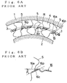
- Fig. 6(A) is a partial section view of a one-way clutch configured by a cage 3, a spring (ribbon spring) 16, and sprags 5 serving as engagement members
- Fig. 6(B) is an enlarged view of portion R in Fig. 6(A).
- the one-way clutch in order to enable the cage 3 to synchronize with the rotation of the outer ring, it is often to employ a configuration where a flange portion which is not illustrated, and which radially elongates is disposed in, for example, an end portion of the cage 3 to provide a fastening zone, and the cage is pressingly inserted into the outer ring 1.
- One or two cages 3 an outer cage and an inner cage are used.
- the engagement members 5 (hereinafter, referred to as sprags 5) are placed in pocket 16p which are disposed on the spring 16 circumferentially at regular intervals, and urged in the engagement direction (wedge function direction) by tongues 16c disposed in the spring 16.
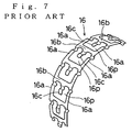
- Fig. 7 is a partial perspective view of the spring 16
- Fig. 8(A) is a plan view which is developed in the circumference direction of the spring 16
- Fig. 8(B) is a section view taken along the line A-A of Fig. 8(A) and a partial section view showing a state where the spring is actually placed in a one-way clutch (the sprags 5 are not placed).
- a thin metal plate member for example, stainless steel
- bases 16a, 16a which are annular when incorporated
- columns 16b, 16b, ... which connect the base 16a and the base 16a
- pockets 16p, 16p, ... which are formed between the base 16a, 16a, ... and the columns 16b and disposed circumferentially at regular intervals
- tongues 16c, 16c, ... which elongate from center portions of the columns 16b toward the pockets are formed by press working.
- the configuration where the tongues 16c have tongues 16c which are previously inward bent before the spring 16 is placed in an annular space 4 has been conventionally known (see Japanese Utility Model Application (Kokai) No. HEI2-76234 ).
- each of the tongues 16c three meandering bends (16d, 16e, 16f) are formed from a basal end portion of the column 16d.
- the height d 2 of a tip end portion of the tongue 16c to the base 16a is smaller than the height d 1 of the second meandering bend 16e to the base 16a, and, in a state where the sprag 5 is urged, the height d 2 of the tip end portion of the tongue 16c to the base 16a is larger than d 1 .
- a drag torque (friction torque) is inevitably generated in power transmission and interruption between inner and outer rings.
- the drag torque depends on a spring force (spring constant) of a tongue of a spring which urges a sprag in the engagement direction.
- spring force spring constant
- the engagement property of a sprag is good, but the drag torque is large.
- the urging force of the tongue is excessively small, the engagement property of the sprag is impaired, and an engagement failure occurs. Therefore, a one-way clutch in which a drag torque is made as small as possible while maintaining the engagement property is requested.
- the invention has been conducted in order to cope with the above-discussed problems. It is an object of the invention to provide a one-way clutch spring which has a high engagement property, and in which a drag torque (friction torque) is considerably lower than the conventional one.
- the height of the tongue to the base, the radii of curvature of the meandering bends which are formed in the column basal end portion of the tongue, the height of the apex of the lowest positioned bend to the base, and the like are largely related to the degree of the urging force exerted on the sprag by the tongue, and that of a drag torque which is generated between the inner and outer rings in power transmission and interruption between the inner and outer rings.
- the drag torque can be made smaller than a conventional one while a force urging a sprag is not weakened and a meshing failure in a wedge function and wedge cancellation function of the sprag does not occur.
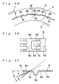
- Fig. 1(A) is a partial section view of a one-way clutch in which the one-way clutch spring of the invention is used
- Fig. 1(B) is an enlarged view of portion P of Fig. 1(A).
- the one-way clutch comprises: a cage 3 which is placed in an annular space 4 between an outer ring 1 and an inner ring 2; sprags 5, 5, ... of an engagement member to be placed in pockets 3p, 3p, ... which are disposed in the cage 3 circumferentially at regular intervals; and a one-way clutch spring 6 (hereinafter, referred to merely as spring 6) which holds the sprags 5, 5, ... to pockets 6p, 6p, ....
- Fig. 2(A) is a partial front view showing a placement state of the spring 6 from which sprags 5 are removed away
- Fig. 2(B) is a partial plan view as seen in the direction of W in Fig. 2(A)
- Fig. 2(C) is an enlarged view of portion Q of Fig. 2(A).
- the spring 6 is configured by: a base 6a, 6a which is annular when it is placed in the annular portion 4; columns 6b which connect the base 6a, 6a; the pockets 6p which are formed by the base 6a and the columns 6b; and tongues 6c which elongate toward the pockets 6p from the columns 6b.
- another cage (not shown) may be disposed at the inner side.
- the configuration of the spring 6 is basically identical with that shown in Figs. 5 to 7.
- urge in the engagement direction is conducted by the tongues 6c, 6c, ... which elongate to the pockets 6p from the columns 6b of the spring 6.
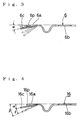
- Each of the tongues 6c which elongate into the pockets 6p is formed so that it has smooth bends 6d, 6e, 6f which are previously bent at a basal end portion of the column 6b before it is placed in the annular space 4, and an initial bending angle ⁇ to the annular base 6a is 25° ⁇ 5°, namely, in the range of 20° to 30°.
- the smooth meandering bends 6d, 6e, 6f are formed in the tongue 6c of the spring 6 which urges the sprag 5, and the sprag 5 is placed in the pocket 6p while the inclination angle ⁇ is a value in the range, whereby the displacement angle ⁇ when the sprag 5 is in contact with the tongue 6c is set so that a spring constant which will be described later is attained. Therefore, an adequate urging force is applied to the sprag 5, and the drag torque can be reduced in the case that a power is transmitted and interrupted between the outer ring 1 and the inner ring 2.
- the sprags 5, 5, ... are placed in the pockets 6p, 6p, ... of the spring 6.
- the sprag 5 makes contact as shown in Fig. 2(C). Therefore, the inclination angle ⁇ between the base 6a and the tongue 6c is increased in the range where the displacement angle ⁇ is the addition of "10° ⁇ 5°" to the inclination angle ⁇ in the case where the sprag 5 makes no contact, or the spring constant of the tongue 6c is increased in the range of 5° to 15° rather than 20° to 30°.
- the bend and the initial inclination angle are disposed so that the inclination angle ⁇ formed by the base 6a and the tongue 6c is in the range of 5° to 15°, and a spring constant is provided so that the displacement angle ⁇ of the tongue 6c of the spring 6 in which the sprag 5 is placed is in the range of 15° to 25°.
- the drag torque in engagement and disengagement states of the sprag 5 tends to be increased by the degree corresponding to the increased displacement amount.
- the inclination angle ( ⁇ + ⁇ ) indicated by the two-dot chain line in Fig. 4 is identical with the angle in the case where the sprag 15 butts against the tongue 16c as shown in Figs. 6(A) and 6(B).
- Fig. 3 shows various angles of the tongue 6c which elongates toward the pocket 6p in the one-way clutch spring 6, to the base 6a.
- “reference” means, for example, repetition of one million, and a repetition number which is required by the user.
- the conventional reference is the case where a spring constant was set so that the displacement angle of the tongues 6c was about 15° to 25° when the sprags 5 were urged while the initial bending angle of the tongues 6c was 5° to 15°.
- the drag torque is smaller than the conventional one, and there is no problem in power transmission and interruption due to engagement and cancellation of the sprags 5.
- Fig. 5 is an enlarged view of portion Q of Fig. 2(A).
- the tongues 6c which elongate into the pockets 6p have smooth meandering bends which are previously bent toward a side that will be inside, at a basal end portion of the column 6b before the sprags 5, 5, ... are placed in the annular space 4. Namely, a first bend 6d, a second bend 6e, and a third bend 6f as seen from the column 6d is formed in each of the tongues 6c.
- all the centers of curvature (Od, Oe, Of) of the bends (6d, 6e, 6f) are positioned on the side of the inner ring 2 with respect to the annular base 6a constituting the spring.
- the bending is performed so that the height h 2 of a tip end portion of the tongue 6c to the base 6a is larger than the height h 1 of the apex of the second bend 6e to the base.
- the radii of curvature R of the three bends (6d, 6e, 6f) are in the range of 0.2 to 0.6 mm. Namely, from the results of experiments, it was found that, when the radii of curvature of these bends (6d, 6e, 6f) are larger than values of this range, the spring constants of the tongues 6 become small, the force of urging the sprags 5 is weakened, and the drag torque becomes large, and, when the radii of curvature of the bends (6d, 6e, 6f) are smaller than values of this range, the spring constants of the tongues 6 become large, the force of urging the sprags 5 is strengthened, and the drag torque becomes large.
Landscapes
- Engineering & Computer Science (AREA)
- General Engineering & Computer Science (AREA)
- Mechanical Engineering (AREA)
- One-Way And Automatic Clutches, And Combinations Of Different Clutches (AREA)
- Springs (AREA)
- Mechanical Operated Clutches (AREA)
- Power Steering Mechanism (AREA)
- Clamps And Clips (AREA)
Abstract
Description
- The present invention relates to a one-way clutch spring to be placed in an annular space between an outer ring and an inner ring of a one-way clutch as it is mentioned in the preamble of the patent claim.
- Such a one-way clutch spring is known from patent abstracts of Japan volume 1995, No. 07, August 31, 1995 and
JP 07-103261 A - The present invention thus relates to a one-way clutch spring which is placed between an inner ring and an outer ring, in which engagement members are placed respectively that exert a wedge function to transmit a power between the inner and outer rings, and that cancel the wedge function to interrupt the power transmission between the inner and outer rings, and which urges the engagement member, and more particularly to a one-way clutch spring which can reduce a drag torque (friction torque) of the engagement members that is generated when a power of a one-way clutch is transmitted or interrupted.
- When power transmission and interruption between an inner ring and an outer ring are to be repeated, a one-way clutch is usually placed between the inner and outer rings.
- Fig. 6(A) is a partial section view of a one-way clutch configured by a
cage 3, a spring (ribbon spring) 16, and sprags 5 serving as engagement members, and Fig. 6(B) is an enlarged view of portion R in Fig. 6(A). In the one-way clutch, in order to enable thecage 3 to synchronize with the rotation of the outer ring, it is often to employ a configuration where a flange portion which is not illustrated, and which radially elongates is disposed in, for example, an end portion of thecage 3 to provide a fastening zone, and the cage is pressingly inserted into theouter ring 1. One or two cages 3 (an outer cage and an inner cage) are used. In any case, the engagement members 5 (hereinafter, referred to as sprags 5) are placed inpocket 16p which are disposed on thespring 16 circumferentially at regular intervals, and urged in the engagement direction (wedge function direction) bytongues 16c disposed in thespring 16. - Fig. 7 is a partial perspective view of the
spring 16, Fig. 8(A) is a plan view which is developed in the circumference direction of thespring 16, and Fig. 8(B) is a section view taken along the line A-A of Fig. 8(A) and a partial section view showing a state where the spring is actually placed in a one-way clutch (thesprags 5 are not placed). - In the
spring 16, a thin metal plate member (for example, stainless steel), andbases columns base 16a and thebase 16a,pockets base columns 16b and disposed circumferentially at regular intervals, andtongues columns 16b toward the pockets are formed by press working. In this case, the configuration where thetongues 16c havetongues 16c which are previously inward bent before thespring 16 is placed in anannular space 4 has been conventionally known (see Japanese Utility Model Application (Kokai)No. HEI2-76234 - In each of the
tongues 16c, three meandering bends (16d, 16e, 16f) are formed from a basal end portion of thecolumn 16d. In such a case, usually, it is most frequent that, as shown in Fig. 9, the height d2 of a tip end portion of thetongue 16c to thebase 16a is smaller than the height d1 of the second meanderingbend 16e to thebase 16a, and, in a state where thesprag 5 is urged, the height d2 of the tip end portion of thetongue 16c to thebase 16a is larger than d1. - In a one-way clutch, a drag torque (friction torque) is inevitably generated in power transmission and interruption between inner and outer rings. In a one-way clutch, the drag torque depends on a spring force (spring constant) of a tongue of a spring which urges a sprag in the engagement direction. Specifically, when an urging force of a tongue is made large (a spring constant is made large), the engagement property of a sprag is good, but the drag torque is large. By contrast, when the urging force of the tongue is excessively small, the engagement property of the sprag is impaired, and an engagement failure occurs. Therefore, a one-way clutch in which a drag torque is made as small as possible while maintaining the engagement property is requested. Recently, from the viewpoint of energy saving, friction loss must be reduced, and, also in a sprag type one-way clutch, a drag torque must be reduced as far as possible. In a one-way clutch for a torque converter or the like, disengage type sprags are used, but reduction of a drag torque in a low rotation zone is not sufficient.
- The invention has been conducted in order to cope with the above-discussed problems. It is an object of the invention to provide a one-way clutch spring which has a high engagement property, and in which a drag torque (friction torque) is considerably lower than the conventional one.
- This object is obtained by a one-way clutch spring indicated in the patent claim.
- In the one-way clutch spring of the present invention the height of the tongue to the base, the radii of curvature of the meandering bends which are formed in the column basal end portion of the tongue, the height of the apex of the lowest positioned bend to the base, and the like are largely related to the degree of the urging force exerted on the sprag by the tongue, and that of a drag torque which is generated between the inner and outer rings in power transmission and interruption between the inner and outer rings. When a one-way clutch spring is configured by the above means, the drag torque can be made smaller than a conventional one while a force urging a sprag is not weakened and a meshing failure in a wedge function and wedge cancellation function of the sprag does not occur.
-
- Fig. 1 shows a one-way clutch in which the one-way clutch spring of the invention is used, Fig. 1(A) is a partial section view, and Fig. 1(B) is an enlarged view of portion P of Fig. 1(A).
- Fig. 2 shows the one-way clutch spring of the invention, Fig. 2(A) is a partial front view, Fig. 2(B) is a plan view as seen in the direction of W in Fig. 2(A), and Fig. 2(C) is an enlarged view of portion Q of Fig. 2(A).
- Fig. 3 is a view showing various angles of a tongue which elongates toward a pocket in a one-way clutch spring, to a base.
- Fig. 4 is a view showing inclination angles of a tongue to a base before a sprag is placed in a pocket of a one-way clutch spring, and in the case where the placed sprag is urged.
- Fig. 5 shows an embodiment of the invention, and is an enlarged view of portion Q of Fig. 2(A).
- Fig. 6 shows a conventional one-way clutch configured by a cage, a spring, and sprags serving as engagement members, Fig. 6(A) is a partial section view, and Fig. 6(B) is an enlarged view of portion R in Fig. 6(A).
- Fig. 7 is a partial perspective view of a spring used in a conventional one-way clutch.
- Fig. 8 shows a conventional spring used in a one-way clutch, Fig. 8(A) is a plan view which is developed in the circumference direction, and Fig. 8(B) is a section view taken along the line A-A of Fig. 8(A).
- Fig. 9 shows a part of a conventional spring in a state where sprags are not placed, and a view showing portion R of Fig. 6(A).
- Hereinafter, a specific embodiment of the invention will be described with reference to drawings.
- Fig. 1(A) is a partial section view of a one-way clutch in which the one-way clutch spring of the invention is used, and Fig. 1(B) is an enlarged view of portion P of Fig. 1(A).
- The one-way clutch comprises: a
cage 3 which is placed in anannular space 4 between anouter ring 1 and aninner ring 2;sprags pockets cage 3 circumferentially at regular intervals; and a one-way clutch spring 6 (hereinafter, referred to merely as spring 6) which holds thesprags pockets - Fig. 2(A) is a partial front view showing a placement state of the
spring 6 from whichsprags 5 are removed away, Fig. 2(B) is a partial plan view as seen in the direction of W in Fig. 2(A), and Fig. 2(C) is an enlarged view of portion Q of Fig. 2(A). - The
spring 6 is configured by: abase annular portion 4;columns 6b which connect thebase pockets 6p which are formed by thebase 6a and thecolumns 6b; andtongues 6c which elongate toward thepockets 6p from thecolumns 6b. - In this case, in addition to the
cage 3, another cage (not shown) may be disposed at the inner side. The configuration of thespring 6 is basically identical with that shown in Figs. 5 to 7. When thesprags tongues pockets 6p from thecolumns 6b of thespring 6. - Each of the
tongues 6c which elongate into thepockets 6p is formed so that it hassmooth bends column 6b before it is placed in theannular space 4, and an initial bending angle α to theannular base 6a is 25° ±5°, namely, in the range of 20° to 30°. - As described above, the smooth meandering
bends tongue 6c of thespring 6 which urges thesprag 5, and thesprag 5 is placed in thepocket 6p while the inclination angle α is a value in the range, whereby the displacement angle γ when thesprag 5 is in contact with thetongue 6c is set so that a spring constant which will be described later is attained. Therefore, an adequate urging force is applied to thesprag 5, and the drag torque can be reduced in the case that a power is transmitted and interrupted between theouter ring 1 and theinner ring 2. - Next, the
sprags pockets spring 6. When they are mounted in theannular space 4 between theouter ring 1 and theinner ring 2, thesprag 5 makes contact as shown in Fig. 2(C). Therefore, the inclination angle β between thebase 6a and thetongue 6c is increased in the range where the displacement angle γ is the addition of "10° ±5°" to the inclination angle α in the case where thesprag 5 makes no contact, or the spring constant of thetongue 6c is increased in the range of 5° to 15° rather than 20° to 30°. - Conventionally, as shown in Fig. 4, before placement in the
annular space 4, the bend and the initial inclination angle are disposed so that the inclination angle α formed by thebase 6a and thetongue 6c is in the range of 5° to 15°, and a spring constant is provided so that the displacement angle γ of thetongue 6c of thespring 6 in which thesprag 5 is placed is in the range of 15° to 25°. - Therefore, the drag torque in engagement and disengagement states of the
sprag 5 tends to be increased by the degree corresponding to the increased displacement amount. The inclination angle (α + γ) indicated by the two-dot chain line in Fig. 4 is identical with the angle in the case where the sprag 15 butts against thetongue 16c as shown in Figs. 6(A) and 6(B). - Fig. 3 shows various angles of the
tongue 6c which elongates toward thepocket 6p in the one-way clutch spring 6, to thebase 6a. - In the completion of the one-
way clutch spring 6 of the invention, tests were conducted while the initial bending angle (spring constant) of thetongues 6c was changed to several kinds (four kinds), thesprags 5 were fitted into thepockets 6p, and the urging force of thetongues 6c against thesprags 5 was changed. Results are listed in Table 1 below.(Table 1) Displacement angle of tongues Initial bending angle of tongues α Idling torque ratio* Locking property Employment 25° or more 5° or less 1 or more Abnormality occurs before reference Disabled 20° ±5° 10° ±5° 1 No problem Enabled 10° ±5° 25° ±5° 0.4 - 0.6 No problem Enabled 5° or less 30° or more 0.4 or less Abnormality occurs before reference Disabled * The idling torque is a drag torque during idling, and "Idling torque ratio" is a ratio which is 1 in the case where the displacement angle of tongues is 20° ±5° and the initial bending angle of tongues is 10° ±5°. - As shown in Table 1, in the case where a spring constant was set so that the displacement angle of the
tongues 6c was 25° or more when thesprags 5 were urged while the initial bending angle of thetongues 6c was 5° or less, the drag torque was larger than the conventional one. In the case where the displacement angle of thetongues 6c was 5° or less when thesprags 5 were urged while the initial bending angle was 30° or larger, the drag torque was 0.4 or less when the conventional one was 1. In the both cases, however, abnormality occurred before the reference. - Namely, the engagement function (transmission of power) and cancellation function (interruption of power) of the
sprags 5 failed to occur in accordance with each other. - In this case, "reference" means, for example, repetition of one million, and a repetition number which is required by the user. However, the conventional reference is the case where a spring constant was set so that the displacement angle of the
tongues 6c was about 15° to 25° when thesprags 5 were urged while the initial bending angle of thetongues 6c was 5° to 15°. As in this case, when a spring constant is set so that the displacement angle of thetongues 6c is about 5° to 15° when thesprags 5 are urged while the initial bending angle of thetongues 6c is 20° to 25°, the drag torque is smaller than the conventional one, and there is no problem in power transmission and interruption due to engagement and cancellation of thesprags 5. - Fig. 5 is an enlarged view of portion Q of Fig. 2(A). The
tongues 6c which elongate into thepockets 6p have smooth meandering bends which are previously bent toward a side that will be inside, at a basal end portion of thecolumn 6b before thesprags annular space 4. Namely, afirst bend 6d, asecond bend 6e, and athird bend 6f as seen from thecolumn 6d is formed in each of thetongues 6c. - Furthermore, all the centers of curvature (Od, Oe, Of) of the bends (6d, 6e, 6f) are positioned on the side of the
inner ring 2 with respect to theannular base 6a constituting the spring. The bending is performed so that the height h2 of a tip end portion of thetongue 6c to thebase 6a is larger than the height h1 of the apex of thesecond bend 6e to the base. - The radii of curvature R of the three bends (6d, 6e, 6f) are in the range of 0.2 to 0.6 mm. Namely, from the results of experiments, it was found that, when the radii of curvature of these bends (6d, 6e, 6f) are larger than values of this range, the spring constants of the
tongues 6 become small, the force of urging thesprags 5 is weakened, and the drag torque becomes large, and, when the radii of curvature of the bends (6d, 6e, 6f) are smaller than values of this range, the spring constants of thetongues 6 become large, the force of urging thesprags 5 is strengthened, and the drag torque becomes large. - According to the invention set forth in
claim 3 of the one-way clutch spring of the invention, about 30% reduction of a drag torque with respect to a spring in which conventional sprags are placed can be realized. There is no problem in engagement and cancellation of sprags and the like, durability is not impaired, and only a change of molds for processing the tongues for a tongue bending R portion is required. Therefore, an excessive cost increase does not occur.
Claims (1)
- A one-way clutch spring (6) to be placed in an annular space between an outer ring and an inner ring of a one-way clutch in which annular space engagement elements are placed, which spring (6) comprises- an annular base (6a),- pockets (6p) formed in the base (6a) in which the engagement elements are to be placed, and- tongues (6c) which extend into said pockets (6p) respectively, wherein- each tongue (6c) has a first bend (6d), a second bend (6e) and a third bend (6f),- said bends (6d, 6e, 6f) being meandering with all centers of curvature being positioned on one side of the base (6a),characterized in that- the height (h2) of the tip end portion of each tongue (6c) over the base (6a) is larger than the height (h1) of the apex of the second bend (6e) over the base (6a) and- the radii of curvature of all bends (6d, 6e, 6f) are in the range of 0,2 to 0,6 mm.
Applications Claiming Priority (5)
| Application Number | Priority Date | Filing Date | Title |
|---|---|---|---|
| JP2003003630 | 2003-01-09 | ||
| JP2003003630A JP2004263705A (en) | 2003-01-09 | 2003-01-09 | Spring for one-way clutch |
| JP2003007826A JP2004263709A (en) | 2003-01-16 | 2003-01-16 | Spring for one-way clutch |
| JP2003007826 | 2003-01-16 | ||
| PCT/JP2004/000132 WO2004063589A1 (en) | 2003-01-09 | 2004-01-09 | One-way clutch spring |
Publications (3)
| Publication Number | Publication Date |
|---|---|
| EP1584831A1 EP1584831A1 (en) | 2005-10-12 |
| EP1584831A4 EP1584831A4 (en) | 2006-04-12 |
| EP1584831B1 true EP1584831B1 (en) | 2007-11-14 |
Family
ID=32716378
Family Applications (1)
| Application Number | Title | Priority Date | Filing Date |
|---|---|---|---|
| EP04701118A Expired - Lifetime EP1584831B1 (en) | 2003-01-09 | 2004-01-09 | One-way clutch spring |
Country Status (5)
| Country | Link |
|---|---|
| US (1) | US7389864B2 (en) |
| EP (1) | EP1584831B1 (en) |
| KR (1) | KR20050086958A (en) |
| DE (1) | DE602004010064T2 (en) |
| WO (1) | WO2004063589A1 (en) |
Cited By (1)
| Publication number | Priority date | Publication date | Assignee | Title |
|---|---|---|---|---|
| CN110291304A (en) * | 2017-03-08 | 2019-09-27 | 博格华纳公司 | With the pawl clutch for inhibiting ratcheting feature |
Families Citing this family (7)
| Publication number | Priority date | Publication date | Assignee | Title |
|---|---|---|---|---|
| DE102005046896A1 (en) * | 2005-09-30 | 2007-04-05 | Schaeffler Kg | Free wheel clutch has inner ring and outer ring wherein throttle has sprags, and retainer with several cases is arranged between inner ring and outer ring |
| EP1921339B1 (en) * | 2006-11-09 | 2014-06-18 | Paul Müller GmbH & Co. KG Unternehmensbeteiligungen | Freewheel with strip element |
| DE112011101462A5 (en) * | 2010-04-29 | 2013-02-07 | Schaeffler Technologies AG & Co. KG | Freewheel, especially for a crank-CVT transmission |
| WO2015171503A1 (en) * | 2014-05-05 | 2015-11-12 | Lifetime Brands, Inc. | Handle for kitchen devices |
| EP3299653B1 (en) | 2016-09-23 | 2020-11-25 | Volvo Car Corporation | Decoupler assembly |
| US10738842B2 (en) * | 2018-12-07 | 2020-08-11 | Schaeffler Technologies AG & Co. KG | Clutch assembly |
| CN112324816B (en) * | 2020-11-06 | 2022-01-21 | 洛阳轴承研究所有限公司 | Inclined strut type overrunning clutch |
Family Cites Families (7)
| Publication number | Priority date | Publication date | Assignee | Title |
|---|---|---|---|---|
| DE1132390B (en) * | 1957-03-25 | 1962-06-28 | Borg Warner | One-way clutch |
| FR2610378B1 (en) * | 1987-01-29 | 1989-08-18 | Skf France | FREE WHEEL DEVICE WITH PUNCH CAMS |
| JP2504134B2 (en) | 1988-09-12 | 1996-06-05 | 日本電気株式会社 | Method for measuring trap level concentration at polycrystalline grain boundaries |
| JPH0276234U (en) * | 1988-11-29 | 1990-06-12 | ||
| JP2594884Y2 (en) * | 1992-04-23 | 1999-05-10 | エヌティエヌ株式会社 | Ribbon spring for one-way clutch |
| JP3009810B2 (en) * | 1993-09-30 | 2000-02-14 | 光洋精工株式会社 | Method of manufacturing ribbon spring for one-way clutch |
| US6892868B2 (en) * | 2001-07-05 | 2005-05-17 | Koyo Seiko Co., Ltd. | One-way clutch |
-
2004
- 2004-01-09 US US10/541,682 patent/US7389864B2/en not_active Expired - Lifetime
- 2004-01-09 DE DE602004010064T patent/DE602004010064T2/en not_active Expired - Lifetime
- 2004-01-09 EP EP04701118A patent/EP1584831B1/en not_active Expired - Lifetime
- 2004-01-09 KR KR1020057012706A patent/KR20050086958A/en not_active Application Discontinuation
- 2004-01-09 WO PCT/JP2004/000132 patent/WO2004063589A1/en active IP Right Grant
Cited By (2)
| Publication number | Priority date | Publication date | Assignee | Title |
|---|---|---|---|---|
| CN110291304A (en) * | 2017-03-08 | 2019-09-27 | 博格华纳公司 | With the pawl clutch for inhibiting ratcheting feature |
| CN110291304B (en) * | 2017-03-08 | 2021-12-03 | 博格华纳公司 | Ratchet clutch with pawl inhibiting feature |
Also Published As
| Publication number | Publication date |
|---|---|
| EP1584831A4 (en) | 2006-04-12 |
| DE602004010064T2 (en) | 2008-09-11 |
| EP1584831A1 (en) | 2005-10-12 |
| US7389864B2 (en) | 2008-06-24 |
| US20060118379A1 (en) | 2006-06-08 |
| DE602004010064D1 (en) | 2007-12-27 |
| WO2004063589A1 (en) | 2004-07-29 |
| KR20050086958A (en) | 2005-08-30 |
Similar Documents
| Publication | Publication Date | Title |
|---|---|---|
| EP1584831B1 (en) | One-way clutch spring | |
| US5180043A (en) | Splined assembly | |
| US3760921A (en) | Clutch disc and method of making | |
| EP1557338B1 (en) | Extensible shaft for steering of vehicle | |
| US6158265A (en) | Method of forming retaining members on a housing | |
| GB2076112A (en) | Slip couplings | |
| EP1653099B1 (en) | Power transmission mechanism of shaft and hub | |
| EP1391626B1 (en) | One-way clutch | |
| US20060042903A1 (en) | Clutch housing and method of manufacturing thereof | |
| US5415258A (en) | One-way clutch having an outer ring whose internal portion is as hard as its periphery | |
| US20030190993A1 (en) | Multiple plate clutch device | |
| US4911273A (en) | One-way clutch with cage-displacement limiting mechanism | |
| EP1798435A1 (en) | Sealing device | |
| JPH0567836U (en) | Wave coil spring | |
| EP0298249B1 (en) | Sliding universal joint | |
| GB2050536A (en) | Freewheel or unidirectional clutch | |
| US8448768B2 (en) | Clutch tooth index and step for multiple cast clutches in one housing | |
| US8016511B2 (en) | Metallic structural part joined from at least two components | |
| US6929106B2 (en) | Multiplate clutch | |
| JP3816544B2 (en) | Wave spring | |
| JP3730736B2 (en) | One-way clutch having a cage with a bearing function | |
| US6868950B2 (en) | Splined annular member and automatic transmission | |
| EP1273816B1 (en) | One-way clutch | |
| WO2017010284A1 (en) | Disc spring | |
| JP4136266B2 (en) | One-way clutch |
Legal Events
| Date | Code | Title | Description |
|---|---|---|---|
| PUAI | Public reference made under article 153(3) epc to a published international application that has entered the european phase |
Free format text: ORIGINAL CODE: 0009012 |
|
| 17P | Request for examination filed |
Effective date: 20050805 |
|
| AK | Designated contracting states |
Kind code of ref document: A1 Designated state(s): AT BE BG CH CY CZ DE DK EE ES FI FR GB GR HU IE IT LI LU MC NL PT RO SE SI SK TR |
|
| AX | Request for extension of the european patent |
Extension state: AL LT LV MK |
|
| A4 | Supplementary search report drawn up and despatched |
Effective date: 20060301 |
|
| DAX | Request for extension of the european patent (deleted) | ||
| RBV | Designated contracting states (corrected) |
Designated state(s): DE FR GB |
|
| RAP1 | Party data changed (applicant data changed or rights of an application transferred) |
Owner name: JTEKT CORPORATION |
|
| 17Q | First examination report despatched |
Effective date: 20060704 |
|
| GRAP | Despatch of communication of intention to grant a patent |
Free format text: ORIGINAL CODE: EPIDOSNIGR1 |
|
| GRAS | Grant fee paid |
Free format text: ORIGINAL CODE: EPIDOSNIGR3 |
|
| GRAA | (expected) grant |
Free format text: ORIGINAL CODE: 0009210 |
|
| AK | Designated contracting states |
Kind code of ref document: B1 Designated state(s): DE FR GB |
|
| REG | Reference to a national code |
Ref country code: GB Ref legal event code: FG4D |
|
| REF | Corresponds to: |
Ref document number: 602004010064 Country of ref document: DE Date of ref document: 20071227 Kind code of ref document: P |
|
| ET | Fr: translation filed | ||
| PGFP | Annual fee paid to national office [announced via postgrant information from national office to epo] |
Ref country code: GB Payment date: 20080125 Year of fee payment: 5 |
|
| PLBE | No opposition filed within time limit |
Free format text: ORIGINAL CODE: 0009261 |
|
| STAA | Information on the status of an ep patent application or granted ep patent |
Free format text: STATUS: NO OPPOSITION FILED WITHIN TIME LIMIT |
|
| 26N | No opposition filed |
Effective date: 20080815 |
|
| GBPC | Gb: european patent ceased through non-payment of renewal fee |
Effective date: 20090109 |
|
| PG25 | Lapsed in a contracting state [announced via postgrant information from national office to epo] |
Ref country code: GB Free format text: LAPSE BECAUSE OF NON-PAYMENT OF DUE FEES Effective date: 20090109 |
|
| REG | Reference to a national code |
Ref country code: DE Ref legal event code: R082 Ref document number: 602004010064 Country of ref document: DE Representative=s name: KILIAN KILIAN & PARTNER, DE Ref country code: DE Ref legal event code: R082 Ref document number: 602004010064 Country of ref document: DE Representative=s name: KILIAN KILIAN & PARTNER MBB PATENTANWAELTE, DE |
|
| REG | Reference to a national code |
Ref country code: FR Ref legal event code: PLFP Year of fee payment: 12 |
|
| PGFP | Annual fee paid to national office [announced via postgrant information from national office to epo] |
Ref country code: FR Payment date: 20150108 Year of fee payment: 12 |
|
| REG | Reference to a national code |
Ref country code: FR Ref legal event code: ST Effective date: 20160930 |
|
| PG25 | Lapsed in a contracting state [announced via postgrant information from national office to epo] |
Ref country code: FR Free format text: LAPSE BECAUSE OF NON-PAYMENT OF DUE FEES Effective date: 20160201 |
|
| PGFP | Annual fee paid to national office [announced via postgrant information from national office to epo] |
Ref country code: DE Payment date: 20221130 Year of fee payment: 20 |
|
| REG | Reference to a national code |
Ref country code: DE Ref legal event code: R071 Ref document number: 602004010064 Country of ref document: DE |