EP1584702B1 - Abscheidungsreparatur von hohlen Gegenständen - Google Patents
Abscheidungsreparatur von hohlen Gegenständen Download PDFInfo
- Publication number
- EP1584702B1 EP1584702B1 EP05252127A EP05252127A EP1584702B1 EP 1584702 B1 EP1584702 B1 EP 1584702B1 EP 05252127 A EP05252127 A EP 05252127A EP 05252127 A EP05252127 A EP 05252127A EP 1584702 B1 EP1584702 B1 EP 1584702B1
- Authority
- EP
- European Patent Office
- Prior art keywords
- insert
- airfoil
- surface portion
- component
- damage site
- Prior art date
- Legal status (The legal status is an assumption and is not a legal conclusion. Google has not performed a legal analysis and makes no representation as to the accuracy of the status listed.)
- Expired - Lifetime
Links
- 230000008439 repair process Effects 0.000 title claims abstract description 29
- 230000008021 deposition Effects 0.000 title claims description 10
- 239000000463 material Substances 0.000 claims abstract description 47
- 238000000034 method Methods 0.000 claims description 37
- 238000000151 deposition Methods 0.000 claims description 15
- 229910000601 superalloy Inorganic materials 0.000 claims description 9
- 150000003839 salts Chemical class 0.000 claims description 8
- 238000003754 machining Methods 0.000 claims description 5
- 150000003841 chloride salts Chemical class 0.000 claims description 4
- 150000004673 fluoride salts Chemical class 0.000 claims description 4
- 238000011065 in-situ storage Methods 0.000 claims description 4
- PNEYBMLMFCGWSK-UHFFFAOYSA-N aluminium oxide Inorganic materials [O-2].[O-2].[O-2].[Al+3].[Al+3] PNEYBMLMFCGWSK-UHFFFAOYSA-N 0.000 claims description 3
- 238000009718 spray deposition Methods 0.000 claims description 3
- 239000000919 ceramic Substances 0.000 claims description 2
- 238000005328 electron beam physical vapour deposition Methods 0.000 claims description 2
- 239000000446 fuel Substances 0.000 claims description 2
- 238000000465 moulding Methods 0.000 claims description 2
- 239000007921 spray Substances 0.000 claims description 2
- 238000009966 trimming Methods 0.000 claims description 2
- 238000005240 physical vapour deposition Methods 0.000 claims 1
- 239000000758 substrate Substances 0.000 claims 1
- 238000003466 welding Methods 0.000 description 5
- 238000001816 cooling Methods 0.000 description 4
- 230000008569 process Effects 0.000 description 4
- PUZPDOWCWNUUKD-UHFFFAOYSA-M sodium fluoride Chemical compound [F-].[Na+] PUZPDOWCWNUUKD-UHFFFAOYSA-M 0.000 description 4
- 238000000859 sublimation Methods 0.000 description 4
- 230000008022 sublimation Effects 0.000 description 4
- 238000005219 brazing Methods 0.000 description 3
- GUTLYIVDDKVIGB-UHFFFAOYSA-N cobalt atom Chemical compound [Co] GUTLYIVDDKVIGB-UHFFFAOYSA-N 0.000 description 3
- 150000001875 compounds Chemical class 0.000 description 3
- 239000000945 filler Substances 0.000 description 3
- 239000000203 mixture Substances 0.000 description 3
- 239000010936 titanium Substances 0.000 description 3
- FAPWRFPIFSIZLT-UHFFFAOYSA-M Sodium chloride Chemical compound [Na+].[Cl-] FAPWRFPIFSIZLT-UHFFFAOYSA-M 0.000 description 2
- 239000010941 cobalt Substances 0.000 description 2
- 229910017052 cobalt Inorganic materials 0.000 description 2
- 238000005516 engineering process Methods 0.000 description 2
- 239000007788 liquid Substances 0.000 description 2
- PQXKHYXIUOZZFA-UHFFFAOYSA-M lithium fluoride Chemical compound [Li+].[F-] PQXKHYXIUOZZFA-UHFFFAOYSA-M 0.000 description 2
- ORUIBWPALBXDOA-UHFFFAOYSA-L magnesium fluoride Chemical compound [F-].[F-].[Mg+2] ORUIBWPALBXDOA-UHFFFAOYSA-L 0.000 description 2
- 229910001635 magnesium fluoride Inorganic materials 0.000 description 2
- 238000004519 manufacturing process Methods 0.000 description 2
- 230000000149 penetrating effect Effects 0.000 description 2
- 235000013024 sodium fluoride Nutrition 0.000 description 2
- 239000011775 sodium fluoride Substances 0.000 description 2
- XLYOFNOQVPJJNP-UHFFFAOYSA-N water Substances O XLYOFNOQVPJJNP-UHFFFAOYSA-N 0.000 description 2
- YPFNIPKMNMDDDB-UHFFFAOYSA-K 2-[2-[bis(carboxylatomethyl)amino]ethyl-(2-hydroxyethyl)amino]acetate;iron(3+) Chemical compound [Fe+3].OCCN(CC([O-])=O)CCN(CC([O-])=O)CC([O-])=O YPFNIPKMNMDDDB-UHFFFAOYSA-K 0.000 description 1
- DGAQECJNVWCQMB-PUAWFVPOSA-M Ilexoside XXIX Chemical compound C[C@@H]1CC[C@@]2(CC[C@@]3(C(=CC[C@H]4[C@]3(CC[C@@H]5[C@@]4(CC[C@@H](C5(C)C)OS(=O)(=O)[O-])C)C)[C@@H]2[C@]1(C)O)C)C(=O)O[C@H]6[C@@H]([C@H]([C@@H]([C@H](O6)CO)O)O)O.[Na+] DGAQECJNVWCQMB-PUAWFVPOSA-M 0.000 description 1
- PXHVJJICTQNCMI-UHFFFAOYSA-N Nickel Chemical compound [Ni] PXHVJJICTQNCMI-UHFFFAOYSA-N 0.000 description 1
- RTAQQCXQSZGOHL-UHFFFAOYSA-N Titanium Chemical compound [Ti] RTAQQCXQSZGOHL-UHFFFAOYSA-N 0.000 description 1
- 239000002253 acid Substances 0.000 description 1
- 150000007513 acids Chemical class 0.000 description 1
- 239000000654 additive Substances 0.000 description 1
- 229910045601 alloy Inorganic materials 0.000 description 1
- 239000000956 alloy Substances 0.000 description 1
- 229910010293 ceramic material Inorganic materials 0.000 description 1
- 238000001311 chemical methods and process Methods 0.000 description 1
- 238000006243 chemical reaction Methods 0.000 description 1
- 239000011248 coating agent Substances 0.000 description 1
- 238000000576 coating method Methods 0.000 description 1
- 238000011109 contamination Methods 0.000 description 1
- 229910052593 corundum Inorganic materials 0.000 description 1
- 238000005336 cracking Methods 0.000 description 1
- 238000011161 development Methods 0.000 description 1
- 230000018109 developmental process Effects 0.000 description 1
- 238000005553 drilling Methods 0.000 description 1
- 230000003628 erosive effect Effects 0.000 description 1
- 238000011049 filling Methods 0.000 description 1
- 238000010304 firing Methods 0.000 description 1
- 230000009969 flowable effect Effects 0.000 description 1
- 238000010438 heat treatment Methods 0.000 description 1
- 230000006872 improvement Effects 0.000 description 1
- 238000007689 inspection Methods 0.000 description 1
- 238000009434 installation Methods 0.000 description 1
- 238000005495 investment casting Methods 0.000 description 1
- 239000006193 liquid solution Substances 0.000 description 1
- 239000006194 liquid suspension Substances 0.000 description 1
- 230000008018 melting Effects 0.000 description 1
- 238000002844 melting Methods 0.000 description 1
- 238000003801 milling Methods 0.000 description 1
- 238000012986 modification Methods 0.000 description 1
- 230000004048 modification Effects 0.000 description 1
- NJPPVKZQTLUDBO-UHFFFAOYSA-N novaluron Chemical compound C1=C(Cl)C(OC(F)(F)C(OC(F)(F)F)F)=CC=C1NC(=O)NC(=O)C1=C(F)C=CC=C1F NJPPVKZQTLUDBO-UHFFFAOYSA-N 0.000 description 1
- 239000002245 particle Substances 0.000 description 1
- 239000013618 particulate matter Substances 0.000 description 1
- 230000035515 penetration Effects 0.000 description 1
- 238000002360 preparation method Methods 0.000 description 1
- 238000012545 processing Methods 0.000 description 1
- 239000011253 protective coating Substances 0.000 description 1
- 238000002407 reforming Methods 0.000 description 1
- 238000007569 slipcasting Methods 0.000 description 1
- 229910052708 sodium Inorganic materials 0.000 description 1
- 239000011734 sodium Substances 0.000 description 1
- 239000011780 sodium chloride Substances 0.000 description 1
- 238000005507 spraying Methods 0.000 description 1
- 238000005979 thermal decomposition reaction Methods 0.000 description 1
- 229910052719 titanium Inorganic materials 0.000 description 1
- 230000008016 vaporization Effects 0.000 description 1
- 238000013022 venting Methods 0.000 description 1
- 229910001845 yogo sapphire Inorganic materials 0.000 description 1
Images


Classifications
-
- B—PERFORMING OPERATIONS; TRANSPORTING
- B23—MACHINE TOOLS; METAL-WORKING NOT OTHERWISE PROVIDED FOR
- B23P—METAL-WORKING NOT OTHERWISE PROVIDED FOR; COMBINED OPERATIONS; UNIVERSAL MACHINE TOOLS
- B23P6/00—Restoring or reconditioning objects
- B23P6/002—Repairing turbine components, e.g. moving or stationary blades, rotors
- B23P6/007—Repairing turbine components, e.g. moving or stationary blades, rotors using only additive methods, e.g. build-up welding
-
- C—CHEMISTRY; METALLURGY
- C23—COATING METALLIC MATERIAL; COATING MATERIAL WITH METALLIC MATERIAL; CHEMICAL SURFACE TREATMENT; DIFFUSION TREATMENT OF METALLIC MATERIAL; COATING BY VACUUM EVAPORATION, BY SPUTTERING, BY ION IMPLANTATION OR BY CHEMICAL VAPOUR DEPOSITION, IN GENERAL; INHIBITING CORROSION OF METALLIC MATERIAL OR INCRUSTATION IN GENERAL
- C23C—COATING METALLIC MATERIAL; COATING MATERIAL WITH METALLIC MATERIAL; SURFACE TREATMENT OF METALLIC MATERIAL BY DIFFUSION INTO THE SURFACE, BY CHEMICAL CONVERSION OR SUBSTITUTION; COATING BY VACUUM EVAPORATION, BY SPUTTERING, BY ION IMPLANTATION OR BY CHEMICAL VAPOUR DEPOSITION, IN GENERAL
- C23C4/00—Coating by spraying the coating material in the molten state, e.g. by flame, plasma or electric discharge
- C23C4/01—Selective coating, e.g. pattern coating, without pre-treatment of the material to be coated
-
- C—CHEMISTRY; METALLURGY
- C23—COATING METALLIC MATERIAL; COATING MATERIAL WITH METALLIC MATERIAL; CHEMICAL SURFACE TREATMENT; DIFFUSION TREATMENT OF METALLIC MATERIAL; COATING BY VACUUM EVAPORATION, BY SPUTTERING, BY ION IMPLANTATION OR BY CHEMICAL VAPOUR DEPOSITION, IN GENERAL; INHIBITING CORROSION OF METALLIC MATERIAL OR INCRUSTATION IN GENERAL
- C23C—COATING METALLIC MATERIAL; COATING MATERIAL WITH METALLIC MATERIAL; SURFACE TREATMENT OF METALLIC MATERIAL BY DIFFUSION INTO THE SURFACE, BY CHEMICAL CONVERSION OR SUBSTITUTION; COATING BY VACUUM EVAPORATION, BY SPUTTERING, BY ION IMPLANTATION OR BY CHEMICAL VAPOUR DEPOSITION, IN GENERAL
- C23C4/00—Coating by spraying the coating material in the molten state, e.g. by flame, plasma or electric discharge
- C23C4/02—Pretreatment of the material to be coated, e.g. for coating on selected surface areas
-
- F—MECHANICAL ENGINEERING; LIGHTING; HEATING; WEAPONS; BLASTING
- F01—MACHINES OR ENGINES IN GENERAL; ENGINE PLANTS IN GENERAL; STEAM ENGINES
- F01D—NON-POSITIVE DISPLACEMENT MACHINES OR ENGINES, e.g. STEAM TURBINES
- F01D5/00—Blades; Blade-carrying members; Heating, heat-insulating, cooling or antivibration means on the blades or the members
- F01D5/005—Repairing methods or devices
-
- F—MECHANICAL ENGINEERING; LIGHTING; HEATING; WEAPONS; BLASTING
- F01—MACHINES OR ENGINES IN GENERAL; ENGINE PLANTS IN GENERAL; STEAM ENGINES
- F01D—NON-POSITIVE DISPLACEMENT MACHINES OR ENGINES, e.g. STEAM TURBINES
- F01D5/00—Blades; Blade-carrying members; Heating, heat-insulating, cooling or antivibration means on the blades or the members
- F01D5/12—Blades
- F01D5/14—Form or construction
- F01D5/18—Hollow blades, i.e. blades with cooling or heating channels or cavities; Heating, heat-insulating or cooling means on blades
- F01D5/187—Convection cooling
-
- F—MECHANICAL ENGINEERING; LIGHTING; HEATING; WEAPONS; BLASTING
- F05—INDEXING SCHEMES RELATING TO ENGINES OR PUMPS IN VARIOUS SUBCLASSES OF CLASSES F01-F04
- F05D—INDEXING SCHEME FOR ASPECTS RELATING TO NON-POSITIVE-DISPLACEMENT MACHINES OR ENGINES, GAS-TURBINES OR JET-PROPULSION PLANTS
- F05D2240/00—Components
- F05D2240/10—Stators
- F05D2240/12—Fluid guiding means, e.g. vanes
- F05D2240/122—Fluid guiding means, e.g. vanes related to the trailing edge of a stator vane
-
- F—MECHANICAL ENGINEERING; LIGHTING; HEATING; WEAPONS; BLASTING
- F05—INDEXING SCHEMES RELATING TO ENGINES OR PUMPS IN VARIOUS SUBCLASSES OF CLASSES F01-F04
- F05D—INDEXING SCHEME FOR ASPECTS RELATING TO NON-POSITIVE-DISPLACEMENT MACHINES OR ENGINES, GAS-TURBINES OR JET-PROPULSION PLANTS
- F05D2240/00—Components
- F05D2240/20—Rotors
- F05D2240/30—Characteristics of rotor blades, i.e. of any element transforming dynamic fluid energy to or from rotational energy and being attached to a rotor
- F05D2240/304—Characteristics of rotor blades, i.e. of any element transforming dynamic fluid energy to or from rotational energy and being attached to a rotor related to the trailing edge of a rotor blade
-
- Y—GENERAL TAGGING OF NEW TECHNOLOGICAL DEVELOPMENTS; GENERAL TAGGING OF CROSS-SECTIONAL TECHNOLOGIES SPANNING OVER SEVERAL SECTIONS OF THE IPC; TECHNICAL SUBJECTS COVERED BY FORMER USPC CROSS-REFERENCE ART COLLECTIONS [XRACs] AND DIGESTS
- Y10—TECHNICAL SUBJECTS COVERED BY FORMER USPC
- Y10T—TECHNICAL SUBJECTS COVERED BY FORMER US CLASSIFICATION
- Y10T29/00—Metal working
- Y10T29/49—Method of mechanical manufacture
- Y10T29/49316—Impeller making
- Y10T29/49318—Repairing or disassembling
-
- Y—GENERAL TAGGING OF NEW TECHNOLOGICAL DEVELOPMENTS; GENERAL TAGGING OF CROSS-SECTIONAL TECHNOLOGIES SPANNING OVER SEVERAL SECTIONS OF THE IPC; TECHNICAL SUBJECTS COVERED BY FORMER USPC CROSS-REFERENCE ART COLLECTIONS [XRACs] AND DIGESTS
- Y10—TECHNICAL SUBJECTS COVERED BY FORMER USPC
- Y10T—TECHNICAL SUBJECTS COVERED BY FORMER US CLASSIFICATION
- Y10T29/00—Metal working
- Y10T29/49—Method of mechanical manufacture
- Y10T29/49718—Repairing
- Y10T29/49732—Repairing by attaching repair preform, e.g., remaking, restoring, or patching
Definitions
- the invention relates to the restoration of turbomachine parts. More particularly, the invention relates to the restoration of worn or damaged gas turbine engine fan, compressor and turbine blades and vanes made of nickel-, cobalt-, iron-, or titanium-based superalloys.
- the components of gas turbine engines are subject to wear and damage. Even moderate wear and damage of certain components may interfere with optimal operation of the engine. Particular areas of concern involve the airfoils of various blades and vanes. Wear and damage may interfere with their aerodynamic efficiency, produce dynamic force imbalances, and even structurally compromise the worn/damaged parts in more extreme cases. A limited reconditioning is commonly practiced for slightly worn or damaged airfoils wherein additional material is removed below the wear/damage to provide the airfoil with a relatively efficient and clean sectional profile albeit smaller than the original or prior profile.
- U.S. Patent No. 4,822,248 discloses use of a plasma torch to deposit nickel- or cobalt-based superalloy material.
- U.S. Patent No. 5,732,467 identifies the use of high velocity oxy-fuel (HVOF) and low pressure plasma spray (LPPS) techniques for repairing cracks in such turbine elements.
- HVOF high velocity oxy-fuel
- LPPS low pressure plasma spray
- U.S. Patent No. 5,783,318 also identifies LPPS techniques in addition to laser welding and plasma transferred are welding.
- U.S. Patent No. 6,049,978 identifies further use of HVOF techniques. Such techniques have offered a limited ability to build up replacement material to restore an original or near original cross-section. However, the structural properties of the replacement material may be substantially limited relative to those of the base material.
- the deposited repair material may, in major part, replace the first material.
- the component may be an internally-cooled gas turbine engine turbine section element.
- the repair material may be selected from the group consisting of Ni-, Co-, Fe-, or Ti-based superalloys.
- the component may be a blade having an airfoil and the damage site may be along a leading edge of the airfoil or a tip of the airfoil.
- the first material maybe lost to a depth of at least 2.0 mm.
- the depositing may involve at least one of: plasma spray deposition; high velocity oxy-fucl deposition; low pressure plasma spray deposition; and electron beam physical vapor deposition.
- Deposited repair material may be machined to restore an external contour of the airfoil.
- the placing may involve forming in situ or trimming a pre-formed insert.
- the removing may involve at least one of chemically removing and thermally removing.
- a sacrificial insert for restoring a turbine airfoil element having an internal space comprising: a first surface portion for registering the insert with an intact internal surface of the turbine airfoil element; and a second surface portion having a shape effective to re-form an internal surface portion of the element bounding the internal space; characterised in that the insert is arranged such that the second surface portion at least partially protrudes from an intact portion of the turbine airfoil element when, in use, the first surface portion is registered with the intact internal surface.
- the insert may consist essentially of one or more salts or of one or more ceramics.
- the insert may consist in major part of one or more salts selected from the group consisting of chlorides and fluorides.
- the insert may consist in major part of alumina.
- the first and second surface portions may include associated portions of pressure and suction side faces of the insert and may define surface enhancements to be replaced/restored.
- FIG. 1 shows a turbine element (e.g., a gas turbine engine turbine section blade 22).
- the exemplary blade 22 includes an airfoil 24 extending from a root 26 at a platform 28 to a tip 30.
- the airfoil has leading and trailing edges 32 and 34 separating pressure and suction sides 36 and 38.
- the platform has an outboard portion 40 for forming an inboard boundary/wall of a core flowpath through the turbine engine.
- a mounting portion or blade root 42 depends centrally from the underside of the platform 40 for fixing the blade in a disk of the turbine engine.
- all or some portion e.g., the platform 40 and airfoil 24
- a cooling passageway network may extend through the blade from one or more inlets in the root to multiple outlets along the blade sides, edges, tip, and/or root.
- Exemplary blades may be made from nickel- or cobalt-based superalloys.
- FIG. 2 shows portions of the cooling passageway network.
- the illustrated blade and network are illustrative. Those skilled in the art will recognize that other component envelope and passageway configurations are possible.
- the network includes a leading passageway or cavity 50, a second cavity 52 aft thereof, a third cavity 54 aft thereof, and a fourth cavity or trailing edge slot 56 yet further aft
- FIG. 3 shows an implementation wherein the leading cavity 50 directs a cooling flow 60 from inboard to outboard and incrementally exiting through a spanwise series of leading edge cooling outlet passageways 62 in a leading edge wall portion 64.
- the second cavity 52 is separated from the leading cavity 50 by a wall portion 66.
- the exemplary second and third cavities are legs of a single passageway separated by a wall portion 68, with the second cavity 52 carrying a flow 68 in an outboard direction and the third cavity 54 returning the flow in an inboard direction.
- the second and third cavities may contain pedestal stubs 70 or other surface enhancements extending from pressure and suction side surfaces of respective pressure and suction side wall portions 72 and 74 ( FIG. 2 ). Alternatively or additionally, pedestals (not shown) may extend between the sides.
- the inboard flow through the third cavity 54 incrementally exits aft through apertures 80 in a wall 82 dividing the third cavity from the slot 56.
- the slot 56 extends to the trailing edge and has a number of pedestals 84 extending between pressure and suction side surfaces of the respective pressure and suction side wall portions.
- the tip 30 has a tip cavity or pocket 90 separated from the internal cavities by a wall 92 and having outlet passageways 94 therein for venting air from the flow 68.
- FIG. 4 shows localized damage such as is associated with foreign object damage (FOD) nicking or chipping the airfoil proximate the leading edge to create a damaged leading portion penetrating to and exposing the leading cavity 50.
- the exemplary damaged surface 96 includes portions along leading portions of the walls 72 and 74.
- the airfoil may be subject to more general damage such as wear or erosion. Even when the damage itself does not penetrate the leading cavity, the penetration may be close enough to the leading cavity that repair attempts may penetrate the cavity. For example, it may be desired to true damage surfaces prior to repair as is described in US patent application US 2004172825 . Such truing may penetrate the cavity.
- repair material may be deposited in association with a cavity or other part internal space.
- the damage site is advantageously cleaned of contamination.
- Protective coatings may be locally or globally removed. Further removal of base material may provide an advantageous base surface for receiving deposition.
- the remaining base material of the blade is ground to a preset configuration such as providing an angled leading facet or base surface 120 ( FIG. 5 ).
- the exemplary base surface 120 has portions on opposite sides of an exposed opening to the leading cavity (e.g., portions along the pressure and suction side wall portions 72 and 74).
- a sacrificial element 130 is placed within the leading cavity.
- An exemplary sacrificial element is formed in situ by injecting a flowable material into the cavity and permitting the material to harden.
- exemplary material is an aqueous paste (e.g., a salt-based filler compound) which dries in place.
- aqueous paste e.g., a salt-based filler compound
- Advantageous composition of the filler compounds and advantageous filling techniques, as well as subsequent removal techniques may depend upon the part material and the cavity shape and dimensions.
- filler material may be applied by spraying (e.g., gas plasma, plasma, etc.).
- a slip casting process may be used.
- a slip is a liquid suspension and/or solution containing particulate matter.
- the opening at the damage site may be plugged or covered (e.g., via a tape mask) to locally close the cavity.
- the liquid may then be introduced to the cavity (e.g., via pouring through the root of a blade). As the liquid evaporates, the particulate is left behind forming a crust on the surface of the cavity. Additives may give the crust enhanced structural integrity if the flocculated particles don't have sufficient structural integrity themselves. This crust can be baked at a low temperature to obtain the structural integrity if needed.
- the plug/cap/mask may be removed.
- Chlorides and fluorides or their mixtures may be used that sublimate upon heating above a sublimation temperature under vacuum. This permits their removal (described below) via sublimation. Salts and other compounds soluble in water, acids, or sodium solutions could be used for removal via dissolving and/or chemical reaction.
- sublimable materials may be advantageous due to limited exposed surface area for dissolving.
- Sodium fluoride will start to sublimate in the vicinity of 850C; magnesium fluoride at 980C; and a double salt of sodium fluoride and magnesium fluoride at 900C.
- lithium fluoride may advantageously be used due to a lower sublimation temperature in the vicinity of 750C.
- sodium chloride may advantageously be used due to either its ease of dissolving in water or its much lower sublimation temperature in the vicinity of 700C.
- the element 130 has an exterior surface with a portion 132 contacting an intact portion of a cavity-defining surface 134 and a portion 136 exposed.
- the portion 136 advantageously complements the lost portion of the cavity-defining surface and protrudes beyond an opening in the damaged cavity.
- the protrusion may be sculpted to have the desired shape.
- the sacrificial element may be formed prior to the machining of the base surface or other treatment.
- repair material 150 is deposited atop the base surface 120 and element surface portion 136 to gradually build up to at least partially replace the lost material and, preferably, more than replace it.
- Deposition may be as described in US patent applications US 2004 172825 , US 2004192826 , 2004172827 , and US 2005 205415 or otherwise.
- the deposited material may be trimmed back to an external surface contour 152 corresponding to the contour of the lost material ( FIG. 6 ) such as via machining and the element 130 may be destructively removed such as by chemical processes (e.g., dissolving, reacting, and the like) and/or thermal processes (e.g., melting, vaporizing, thermal decomposition, and the like).
- thermal processes e.g., melting, vaporizing, thermal decomposition, and the like.
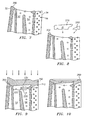
- FIG. 7 shows damage to the tip area of the blade of FIG. 3 .
- a tip portion has been removed completely between the leading and trailing edges 32 and 34 penetrating to the cavities 52, and 54 and the slot 56, although other damage is possible.
- a damaged surface is shown as 200. Material may be removed from below the surface 200 to create one or more facets 202 ( FIG. 8 ) or other prepared surfaces for receiving deposition material.
- FIG. 8 shows pre-formed insert elements 210 and 212 which may be inserted (e.g., partially into the opening(s) to the cavities created at the damage site by the damage and/or by subsequent machining).
- Exemplary inserts are molded from the aforementioned salts (e.g., chlorides, fluorides or their mixtures) or other materials heretofore or subsequently used for to manufacture investment casting cores and shells (e.g., Al 2 O 3 ).
- the inserts may be made using existing or subsequent core-manufacturing technology (e.g., molding and firing of ceramic materials).
- FIG. 9 shows the inserts 210 and 212 in place.
- the exemplary insert 210 is a main insert for restoring the inboard surface of the end wall 92 along the cavities 52 and 54.
- the exemplary insert 212 is a trailing slot insert for restoring the inboard surface of the end wall along the slot 56.
- the inserts When associated with flat cavities having generally parallel sides, the inserts may be flat having corresponding side surfaces, a portion of each of which may engage an intact portion of the associated cavity-defining surface and a remaining portion of which protrudes.
- the side surfaces may have blind or through apertures corresponding to surface area enhancements (e.g., pedestals, posts, trip strips, wall portions and the like to be replaced or restored)
- the exemplary first insert 210 has a perimeter surface portion 220 dimensioned to be positioned within the associated cavities 52 and 54.
- the perimeter portion 220 may itself have portions such as 222 defining blind slots for engaging associated intact pedestals or other intact structure.
- the perimeter has a second portion 230 along the protruding portion of the insert for reforming the inboard surface of the wall 92 of FIG. 3 .
- the second insert may be similxly formed.
- inserts may be preformed in their final conditions in which case it may be appropriate to machine the damaged area down to a single predetermined configuration regardless of the extent of the damage as long as such damage is within a wide range appropriate for repair with such insert.
- inserts may initially be maximally sized or otherwise oversized.
- an insert could be up to a near positive of an entire passageway network or portion thereof. With relatively minimal machining or other preparation of the damage site a portion of the insert may be cut off for installation. This portion may correspond to the portion necessary to protrude from the damaged area and a small portion sufficient to extend into the undamaged area and register the insert. The remainder of the insert could be discarded or even used for other repairs of other areas of the same or a similar airfoil.
- FIG. 9 further shows repair material 250 deposited atop the base surface defined by the facets 202 and the surfaces of the inserts protruding from the airfoil. After deposition, as with the leading edge repair, the tip area may be machined to restore the final surface contour of the airfoil, including milling of the tip pocket and drilling of the passageways 94. The insert may be removed and additional processing (if any) performed.
Landscapes
- Engineering & Computer Science (AREA)
- Chemical & Material Sciences (AREA)
- Mechanical Engineering (AREA)
- Metallurgy (AREA)
- Plasma & Fusion (AREA)
- Physics & Mathematics (AREA)
- Chemical Kinetics & Catalysis (AREA)
- Materials Engineering (AREA)
- General Engineering & Computer Science (AREA)
- Organic Chemistry (AREA)
- Turbine Rotor Nozzle Sealing (AREA)
- Physical Vapour Deposition (AREA)
- Application Of Or Painting With Fluid Materials (AREA)
- Furnace Housings, Linings, Walls, And Ceilings (AREA)
- Separation Using Semi-Permeable Membranes (AREA)
- Structures Of Non-Positive Displacement Pumps (AREA)
Claims (25)
- Verfahren zur Wiederaufbereitung einer Komponente (22), die einen internen Raum (50, 52, 54, 56) aufweist und welche erstes Material von einer Schadensseite (96, 200) verloren hat, umfassend:Platzieren zumindest eines ersten Flächenbereichs (132, 220) eines Opferelements (130, 210, 212) innerhalb des internen Raums;Abscheiden eines Reparaturmaterials (150, 250) zumindest teilweise anstelle des ersten Materials; undEntfernen des Opferelements,dadurch gekennzeichnet, dass:das Opferelement einen zweiten Flächenbereich (136, 230) aufweist, der eine Form aufweist, die dazu ausgebildet ist, einen internen Flächenbereich der Komponente, der den internen Raum begrenzt, umzugestalten;wobei das Platzieren den zweiten Flächenbereich dazu veranlasst, zumindest teilweise von einem intakten Bereich der Komponente hervorzustehen; undwobei das Ablegen des Reparaturmaterials das Ablegen des Reparaturmaterials oben auf den zweiten Flächenbereich beinhaltet.
- Verfahren nach Anspruch 1, wobei:die Schadensseite sich zu dem internen Raum erstreckt.
- Verfahren nach Anspruch 1 oder 2, wobei:der zweite Flächenbereich (136, 230) des Opferelements zumindest ein internes Merkmal aufweist, das aus der Gruppe ausgewählt ist, die aus Absätzen, Stäben, und Nockenstreifen besteht.
- Verfahren nach einem der vorangehenden Ansprüche, wobei:das Verfahren des Weiteren das Entfernen von Zusatzmaterial zumindest teilweise von der Schadensseite umfasst, um eine Basisfläche (202) zu erzeugen; unddas Ablegen das Reparaturmaterial (10, 250) oben auf der Basisfläche zumindest teilweise anstelle des ersten Materials und des Zusatzmaterials ablegt.
- Verfahren nach einem der vorangehenden Ansprüche, wobei:das abgelegte Reparaturmaterial (150, 250) im Hauptteil das erste Material ersetzt.
- Verfahren nach einem der vorangehenden Ansprüche, wobei:die Komponente (22) ein intern gekühltes Gasturbinenmaschinen-Turbinenbereichselements ist.
- Verfahren nach einem der vorangehenden Ansprüche, wobei das Reparaturmaterial (150, 250) aus der Gruppe ausgewählt ist, die aus Ni-, Co-, Fe-, oder Ti-basierten Superlegierungen besteht.
- Verfahren nach einem der vorangehenden Ansprüche, wobei die Komponente (22) ein Substratmaterial umfasst, das aus der Gruppe ausgewählt ist, die aus Ni-, Co-, Fe-, oder Ti-basierten Superlegierungen besteht.
- Verfahren nach einem der vorangehenden Ansprüche, wobei die Komponente (22) eine Laufschaufel ist, die ein Strömungsprofil (24) aufweist, und wobei die Schadensseite (56) entlang einer Vorderkante (32) des Strömungsprofils ist.
- Verfahren nach einem der Ansprüche 1 bis 8, wobei die Komponente (22) eine Laufschaufel ist, die ein Strömungsprofil (24) aufweist, und wobei die Schadensseite (200) entlang einer Spitze (30) des Strömungsprofils ist.
- Verfahren nach einem der Ansprüche 1 bis 8, wobei die Komponente (22) eine Laufschaufel ist, die ein Strömungsprofil (24) aufweist, und wobei die Schadensseite entlang einer Hinterkante (34) des Strömungsprofils ist.
- Verfahren nach einem der Ansprüche 1 bis 8, wobei die Komponente (22) eine Laufschaufel ist, die eine Plattform (28) und ein Strömungsprofil (24) aufweist, und wobei die Schadensseite entlang der Plattform ist.
- Verfahren nach einem der vorangehenden Ansprüche, wobei das erste Material zu einer Tiefe von zumindest 2,0 mm verschwunden ist.
- Verfahren nach einem der vorangehenden Ansprüche, wobei das Abscheiden zumindest eines umfasst aus:Plasmasprühabscheiden; Hochgeschwindigkeits-Flammspritzabscheiden (HVOF); Niederdruck-Plasmasprühabscheiden (LPPS); und physikalisches Elektronstrahl-Dampfabscheiden (EB PVD).
- Verfahren nach einem der vorangehenden Ansprüche, des Weiteren umfassend:Bearbeiten des abgelegten Reparaturmaterials (150, 250), um eine äußere Kontur der Komponente (22) wiederherzustellen.
- Verfahren nach einem der vorangehenden Ansprüche, wobei das Platzieren in-Situ-Formen umfasst.
- Verfahren nach einem der Ansprüche 1 bis 15, wobei das Platzieren das Trimmen eines vorgeformten Einsatzes (130; 210, 212) umfasst.
- Verfahren nach Anspruch 17, des Weiteren umfassend:Formen des Einsatzes durch Formpressen.
- Verfahren nach einem der vorangehenden Ansprüche, wobei das Entfernen zumindest eines von chemikalischem Entfernen und thermischem Entfernen umfasst.
- Opfereinsatz (210) zur Wiederherstellung eines Turbinenströmungsprofilelements (220), das einen internen Raum (50; 52, 54, 56) aufweist, umfassend:einen ersten Flächenbereich (220) zum Eingreifen des Einsatzes mit einer in-takten internen Fläche (202) des Turbinenströmungsprofilelements;und dadurch gekennzeichnet, dassein zweiter Flächenbereich (230) eine Form aufweist, die dazu ausgebildet ist, einen internen Flächenbereich des Elements, das den internen Raum begrenzt, umzugestalten;der Einsatz derart angeordnet ist, dass der zweite Flächenbereich zumindest teilweise von einem intakten Bereich des Turbinenströmungsprofilelements hervorsteht, wenn im Betrieb der erste Flächenbereich mit der intakten internen Fläche im Eingriff ist.
- Einsatz nach Anspruch 20, im Wesentlichen bestehend aus:einem oder mehreren Salzen; odereiner oder mehreren Keramiken.
- Einsatz nach Anspruch 20 oder 21, bestehend im Hauptteil aus einem oder mehr Salzen, die aus einer Gruppe ausgewählt sind, die aus Chloriden und Fluoriden besteht.
- Einsatz nach Anspruch 20 oder 21, bestehend im Hauptteil aus Aluminium.
- Einsatz nach einem der Ansprüche 20 bis 23, wobei:der erste und der zweite Flächenbereich zugehörige Bereiche von Druck- und Saugseitenflächen des Einsatzes beinhalten.
- Einsatz nach einem der Ansprüche 20 bis 24, wobei:der erste und der zweite Flächenbereich eine oder mehrere interne Flächenerweiterungen aufweisen.
Applications Claiming Priority (2)
| Application Number | Priority Date | Filing Date | Title |
|---|---|---|---|
| US818962 | 1997-03-14 | ||
| US10/818,962 US20050217110A1 (en) | 2004-04-06 | 2004-04-06 | Deposition repair of hollow items |
Publications (2)
| Publication Number | Publication Date |
|---|---|
| EP1584702A1 EP1584702A1 (de) | 2005-10-12 |
| EP1584702B1 true EP1584702B1 (de) | 2011-01-19 |
Family
ID=34912695
Family Applications (1)
| Application Number | Title | Priority Date | Filing Date |
|---|---|---|---|
| EP05252127A Expired - Lifetime EP1584702B1 (de) | 2004-04-06 | 2005-04-05 | Abscheidungsreparatur von hohlen Gegenständen |
Country Status (9)
| Country | Link |
|---|---|
| US (1) | US20050217110A1 (de) |
| EP (1) | EP1584702B1 (de) |
| JP (1) | JP4121516B2 (de) |
| CN (1) | CN1680068A (de) |
| AT (1) | ATE496151T1 (de) |
| CA (1) | CA2503800A1 (de) |
| DE (1) | DE602005025956D1 (de) |
| SG (1) | SG115822A1 (de) |
| UA (1) | UA90841C2 (de) |
Families Citing this family (30)
| Publication number | Priority date | Publication date | Assignee | Title |
|---|---|---|---|---|
| US7540083B2 (en) * | 2005-09-28 | 2009-06-02 | Honeywell International Inc. | Method to modify an airfoil internal cooling circuit |
| US7552855B2 (en) * | 2005-10-13 | 2009-06-30 | United Technologies Corporation | Hole repair technique and apparatus |
| SG134184A1 (en) * | 2006-01-16 | 2007-08-29 | United Technologies Corp | Chordwidth restoration of a trailing edge of a turbine airfoil by laser clad |
| US20100257733A1 (en) * | 2006-07-20 | 2010-10-14 | Honeywell International, Inc. | High pressure single crystal turbine blade tip repair with laser cladding |
| EP1889680A1 (de) * | 2006-08-16 | 2008-02-20 | Siemens Aktiengesellschaft | Verfahren zum Schweissen von Turbinenbauteilen unter Verwendung eines in einem Hohlraum des Bauteiles eingeführten keramischen Kerns |
| US20090028707A1 (en) * | 2007-07-26 | 2009-01-29 | United Technologies Corporation | Apparatus and method for repairing airfoil tips |
| US8578579B2 (en) * | 2007-12-11 | 2013-11-12 | General Electric Company | System and method for adaptive machining |
| US20090193656A1 (en) * | 2008-02-04 | 2009-08-06 | General Electric Company | Steam turbine bucket with erosion durability |
| DE102008007820A1 (de) * | 2008-02-05 | 2009-08-06 | Mtu Aero Engines Gmbh | Verfahren zur Reparatur eines metallischen Hohlkörpers |
| US20090324841A1 (en) * | 2008-05-09 | 2009-12-31 | Siemens Power Generation, Inc. | Method of restoring near-wall cooled turbine components |
| DE102011089699B4 (de) * | 2011-12-22 | 2013-09-12 | Lufthansa Technik Ag | Vorrichtung zum Rekonturieren einer Gasturbinenschaufel |
| WO2014158245A1 (en) | 2013-03-14 | 2014-10-02 | Hodgson Benedict N | Airfoil with leading edge reinforcement |
| US20150132143A1 (en) * | 2013-11-11 | 2015-05-14 | Gerald J. Bruck | Welding process and reduced restraint weld joint |
| CN103831574B (zh) * | 2013-12-10 | 2016-03-23 | 贵州黎阳航空动力有限公司 | 空心涡轮叶片叶身堵盖修复工艺 |
| EP3061556B1 (de) | 2015-02-26 | 2018-08-15 | Rolls-Royce Corporation | Verfahren zur reparatur von zwei dünnwandigen metallischen komponenten mithilfe von lötmaterial und hergestelltes komponent davon |
| EP3061557B1 (de) | 2015-02-26 | 2018-04-18 | Rolls-Royce Corporation | Reparatur von zwei dünnwandigen metallischen bauteilen mit gerichteter energieablagerungs-materialzugabe |
| US20160354953A1 (en) * | 2015-06-03 | 2016-12-08 | United Technologies Corporation | Repair or remanufacture of cooled components with an oxidation resistant braze |
| US10544683B2 (en) | 2016-08-30 | 2020-01-28 | Rolls-Royce Corporation | Air-film cooled component for a gas turbine engine |
| US20180073390A1 (en) | 2016-09-13 | 2018-03-15 | Rolls-Royce Corporation | Additively deposited gas turbine engine cooling component |
| US10689984B2 (en) | 2016-09-13 | 2020-06-23 | Rolls-Royce Corporation | Cast gas turbine engine cooling components |
| US10487660B2 (en) * | 2016-12-19 | 2019-11-26 | General Electric Company | Additively manufactured blade extension with internal features |
| US10625342B2 (en) * | 2017-02-22 | 2020-04-21 | General Electric Company | Method of repairing turbine component |
| EP3441181A1 (de) * | 2017-08-09 | 2019-02-13 | General Electric Company | Verfahren zur behandlung von aus äquiaxialem material oder direktional erstarrter struktur geformten komponenten sowie behandelte komponenten |
| CN108213832B (zh) * | 2017-12-29 | 2020-08-18 | 西安交通大学 | 一种实现单晶或定向晶合金叶片内流道复形的修复方法 |
| US11338396B2 (en) | 2018-03-08 | 2022-05-24 | Rolls-Royce Corporation | Techniques and assemblies for joining components |
| US11090771B2 (en) | 2018-11-05 | 2021-08-17 | Rolls-Royce Corporation | Dual-walled components for a gas turbine engine |
| US11305363B2 (en) | 2019-02-11 | 2022-04-19 | Rolls-Royce Corporation | Repair of through-hole damage using braze sintered preform |
| US11692446B2 (en) | 2021-09-23 | 2023-07-04 | Rolls-Royce North American Technologies, Inc. | Airfoil with sintered powder components |
| US11524350B1 (en) * | 2021-10-04 | 2022-12-13 | General Electric Company | Backwall strike braze repair |
| US20240410312A1 (en) * | 2023-06-09 | 2024-12-12 | Pratt & Whitney Canada Corp. | High Entropy Alloy Repair of Nickel and Cobalt Superalloys |
Family Cites Families (26)
| Publication number | Priority date | Publication date | Assignee | Title |
|---|---|---|---|---|
| US3576065A (en) * | 1969-03-24 | 1971-04-27 | Chromalloy American Corp | Repair of apertured machine components |
| US4008844A (en) * | 1975-01-06 | 1977-02-22 | United Technologies Corporation | Method of repairing surface defects using metallic filler material |
| US4073639A (en) * | 1975-01-06 | 1978-02-14 | United Technologies Corporation | Metallic filler material |
| US4743462A (en) * | 1986-07-14 | 1988-05-10 | United Technologies Corporation | Method for preventing closure of cooling holes in hollow, air cooled turbine engine components during application of a plasma spray coating |
| US4726104A (en) * | 1986-11-20 | 1988-02-23 | United Technologies Corporation | Methods for weld repairing hollow, air cooled turbine blades and vanes |
| US5106010A (en) * | 1990-09-28 | 1992-04-21 | Chromalloy Gas Turbine Corporation | Welding high-strength nickel base superalloys |
| DE69330018T2 (de) * | 1992-05-06 | 2001-06-21 | United Technologies Corp., Hartford | Wärmebehandlung und verfahren zum reparieren eines superlegierungskörpers auf kobalt-basis |
| US5783318A (en) | 1994-06-22 | 1998-07-21 | United Technologies Corporation | Repaired nickel based superalloy |
| US5511721A (en) * | 1994-11-07 | 1996-04-30 | General Electric Company | Braze blocking insert for liquid phase brazing operations |
| US5640767A (en) * | 1995-01-03 | 1997-06-24 | Gen Electric | Method for making a double-wall airfoil |
| US5553370A (en) * | 1995-02-09 | 1996-09-10 | Pepe; John | Method for repair of steam turbine blades |
| JP3745427B2 (ja) * | 1995-11-14 | 2006-02-15 | Smc株式会社 | 真空圧制御用スロー排気バルブ |
| US5902647A (en) * | 1996-12-03 | 1999-05-11 | General Electric Company | Method for protecting passage holes in a metal-based substrate from becoming obstructed, and related compositions |
| US6049978A (en) * | 1996-12-23 | 2000-04-18 | Recast Airfoil Group | Methods for repairing and reclassifying gas turbine engine airfoil parts |
| US5794338A (en) * | 1997-04-04 | 1998-08-18 | General Electric Company | Method for repairing a turbine engine member damaged tip |
| US6329633B1 (en) * | 1998-11-20 | 2001-12-11 | United Technologies Corporation | Method and material for processing a component for laser machining |
| US6251315B1 (en) * | 1998-11-20 | 2001-06-26 | United Technologies Corporation | Method for disposing a laser blocking material on the interior of an airfoil |
| US6547210B1 (en) * | 2000-02-17 | 2003-04-15 | Wright Medical Technology, Inc. | Sacrificial insert for injection molding |
| US6460754B1 (en) * | 2000-08-02 | 2002-10-08 | Gen Electric | Prevention of braze alloy flow and stopoff material therefor |
| US6427327B1 (en) * | 2000-11-29 | 2002-08-06 | General Electric Company | Method of modifying cooled turbine components |
| EP1350860A1 (de) * | 2002-04-04 | 2003-10-08 | ALSTOM (Switzerland) Ltd | Verfahren zum Abdecken von Kühlungsöffnungen eines Gasturbinebauteils |
| US6754955B1 (en) * | 2003-01-30 | 2004-06-29 | General Electric Company | Method or repairing trailing edge portions of partitions in turbine diaphragms |
| US7509734B2 (en) * | 2003-03-03 | 2009-03-31 | United Technologies Corporation | Repairing turbine element |
| US7216428B2 (en) * | 2003-03-03 | 2007-05-15 | United Technologies Corporation | Method for turbine element repairing |
| US20060248718A1 (en) * | 2005-05-06 | 2006-11-09 | United Technologies Corporation | Superalloy repair methods and inserts |
| US7761989B2 (en) * | 2005-11-22 | 2010-07-27 | United Technologies Corporation | Methods for repairing gas turbine engine components |
-
2004
- 2004-04-06 US US10/818,962 patent/US20050217110A1/en not_active Abandoned
-
2005
- 2005-04-04 CA CA002503800A patent/CA2503800A1/en not_active Abandoned
- 2005-04-05 AT AT05252127T patent/ATE496151T1/de not_active IP Right Cessation
- 2005-04-05 UA UAA200503189A patent/UA90841C2/ru unknown
- 2005-04-05 DE DE602005025956T patent/DE602005025956D1/de not_active Expired - Lifetime
- 2005-04-05 JP JP2005108140A patent/JP4121516B2/ja not_active Expired - Fee Related
- 2005-04-05 SG SG200502022A patent/SG115822A1/en unknown
- 2005-04-05 EP EP05252127A patent/EP1584702B1/de not_active Expired - Lifetime
- 2005-04-06 CN CNA2005100640526A patent/CN1680068A/zh active Pending
Also Published As
| Publication number | Publication date |
|---|---|
| ATE496151T1 (de) | 2011-02-15 |
| EP1584702A1 (de) | 2005-10-12 |
| SG115822A1 (en) | 2005-10-28 |
| CN1680068A (zh) | 2005-10-12 |
| CA2503800A1 (en) | 2005-10-06 |
| US20050217110A1 (en) | 2005-10-06 |
| DE602005025956D1 (de) | 2011-03-03 |
| JP2005299652A (ja) | 2005-10-27 |
| UA90841C2 (ru) | 2010-06-10 |
| JP4121516B2 (ja) | 2008-07-23 |
Similar Documents
| Publication | Publication Date | Title |
|---|---|---|
| EP1584702B1 (de) | Abscheidungsreparatur von hohlen Gegenständen | |
| EP1759799B1 (de) | Verfahren zur Formgebung oder Herstellung von Turbinenmotorelementen | |
| US7966707B2 (en) | Method for repairing superalloy components using inserts | |
| US7216428B2 (en) | Method for turbine element repairing | |
| EP1721697B2 (de) | Reparaturverfahren für Superlegierungen und Inserts | |
| CA1285127C (en) | Methods for weld repairing hollow, air cooled turbine blades and vanes | |
| JP4689120B2 (ja) | タービン羽根のエアフォイルを交換する方法 | |
| EP1880793A2 (de) | Reparatur einer Hochdruck-Einzelturbinenschaufelspitze mittels Laserplattierung | |
| EP1350860A1 (de) | Verfahren zum Abdecken von Kühlungsöffnungen eines Gasturbinebauteils | |
| EP1884306A1 (de) | Reparatur von Gasturbinenbauteilen aus Superlegierungen durch Hybridschweißen | |
| JP2003056359A (ja) | タービンブレードを補修する方法 | |
| JP2007040303A (ja) | タービン構成要素の一部を回復させる方法 | |
| CN113522700A (zh) | 用于涂覆具有开孔的基底的方法 | |
| EP3100819A1 (de) | Reparatur oder neufertigung von gekühlten komponenten mit oxidationsbeständiger hartlötstelle | |
| WO2025221991A1 (en) | Abrasive tip coating | |
| CN120714816A (zh) | 掩蔽系统 |
Legal Events
| Date | Code | Title | Description |
|---|---|---|---|
| PUAI | Public reference made under article 153(3) epc to a published international application that has entered the european phase |
Free format text: ORIGINAL CODE: 0009012 |
|
| AK | Designated contracting states |
Kind code of ref document: A1 Designated state(s): AT BE BG CH CY CZ DE DK EE ES FI FR GB GR HU IE IS IT LI LT LU MC NL PL PT RO SE SI SK TR |
|
| AX | Request for extension of the european patent |
Extension state: AL BA HR LV MK YU |
|
| 17P | Request for examination filed |
Effective date: 20060323 |
|
| AKX | Designation fees paid |
Designated state(s): AT BE BG CH CY CZ DE DK EE ES FI FR GB GR HU IE IS IT LI LT LU MC NL PL PT RO SE SI SK TR |
|
| 17Q | First examination report despatched |
Effective date: 20090422 |
|
| GRAP | Despatch of communication of intention to grant a patent |
Free format text: ORIGINAL CODE: EPIDOSNIGR1 |
|
| GRAS | Grant fee paid |
Free format text: ORIGINAL CODE: EPIDOSNIGR3 |
|
| GRAA | (expected) grant |
Free format text: ORIGINAL CODE: 0009210 |
|
| AK | Designated contracting states |
Kind code of ref document: B1 Designated state(s): AT BE BG CH CY CZ DE DK EE ES FI FR GB GR HU IE IS IT LI LT LU MC NL PL PT RO SE SI SK TR |
|
| REG | Reference to a national code |
Ref country code: GB Ref legal event code: FG4D |
|
| REG | Reference to a national code |
Ref country code: CH Ref legal event code: EP |
|
| REG | Reference to a national code |
Ref country code: IE Ref legal event code: FG4D |
|
| REF | Corresponds to: |
Ref document number: 602005025956 Country of ref document: DE Date of ref document: 20110303 Kind code of ref document: P |
|
| REG | Reference to a national code |
Ref country code: DE Ref legal event code: R096 Ref document number: 602005025956 Country of ref document: DE Effective date: 20110303 |
|
| REG | Reference to a national code |
Ref country code: NL Ref legal event code: VDEP Effective date: 20110119 |
|
| LTIE | Lt: invalidation of european patent or patent extension |
Effective date: 20110119 |
|
| PG25 | Lapsed in a contracting state [announced via postgrant information from national office to epo] |
Ref country code: GR Free format text: LAPSE BECAUSE OF FAILURE TO SUBMIT A TRANSLATION OF THE DESCRIPTION OR TO PAY THE FEE WITHIN THE PRESCRIBED TIME-LIMIT Effective date: 20110420 Ref country code: IS Free format text: LAPSE BECAUSE OF FAILURE TO SUBMIT A TRANSLATION OF THE DESCRIPTION OR TO PAY THE FEE WITHIN THE PRESCRIBED TIME-LIMIT Effective date: 20110519 Ref country code: PT Free format text: LAPSE BECAUSE OF FAILURE TO SUBMIT A TRANSLATION OF THE DESCRIPTION OR TO PAY THE FEE WITHIN THE PRESCRIBED TIME-LIMIT Effective date: 20110519 Ref country code: LT Free format text: LAPSE BECAUSE OF FAILURE TO SUBMIT A TRANSLATION OF THE DESCRIPTION OR TO PAY THE FEE WITHIN THE PRESCRIBED TIME-LIMIT Effective date: 20110119 Ref country code: SE Free format text: LAPSE BECAUSE OF FAILURE TO SUBMIT A TRANSLATION OF THE DESCRIPTION OR TO PAY THE FEE WITHIN THE PRESCRIBED TIME-LIMIT Effective date: 20110119 Ref country code: ES Free format text: LAPSE BECAUSE OF FAILURE TO SUBMIT A TRANSLATION OF THE DESCRIPTION OR TO PAY THE FEE WITHIN THE PRESCRIBED TIME-LIMIT Effective date: 20110430 |
|
| PG25 | Lapsed in a contracting state [announced via postgrant information from national office to epo] |
Ref country code: AT Free format text: LAPSE BECAUSE OF FAILURE TO SUBMIT A TRANSLATION OF THE DESCRIPTION OR TO PAY THE FEE WITHIN THE PRESCRIBED TIME-LIMIT Effective date: 20110119 Ref country code: CY Free format text: LAPSE BECAUSE OF FAILURE TO SUBMIT A TRANSLATION OF THE DESCRIPTION OR TO PAY THE FEE WITHIN THE PRESCRIBED TIME-LIMIT Effective date: 20110119 Ref country code: PL Free format text: LAPSE BECAUSE OF FAILURE TO SUBMIT A TRANSLATION OF THE DESCRIPTION OR TO PAY THE FEE WITHIN THE PRESCRIBED TIME-LIMIT Effective date: 20110119 Ref country code: NL Free format text: LAPSE BECAUSE OF FAILURE TO SUBMIT A TRANSLATION OF THE DESCRIPTION OR TO PAY THE FEE WITHIN THE PRESCRIBED TIME-LIMIT Effective date: 20110119 Ref country code: BE Free format text: LAPSE BECAUSE OF FAILURE TO SUBMIT A TRANSLATION OF THE DESCRIPTION OR TO PAY THE FEE WITHIN THE PRESCRIBED TIME-LIMIT Effective date: 20110119 Ref country code: BG Free format text: LAPSE BECAUSE OF FAILURE TO SUBMIT A TRANSLATION OF THE DESCRIPTION OR TO PAY THE FEE WITHIN THE PRESCRIBED TIME-LIMIT Effective date: 20110419 Ref country code: SI Free format text: LAPSE BECAUSE OF FAILURE TO SUBMIT A TRANSLATION OF THE DESCRIPTION OR TO PAY THE FEE WITHIN THE PRESCRIBED TIME-LIMIT Effective date: 20110119 Ref country code: FI Free format text: LAPSE BECAUSE OF FAILURE TO SUBMIT A TRANSLATION OF THE DESCRIPTION OR TO PAY THE FEE WITHIN THE PRESCRIBED TIME-LIMIT Effective date: 20110119 |
|
| PG25 | Lapsed in a contracting state [announced via postgrant information from national office to epo] |
Ref country code: EE Free format text: LAPSE BECAUSE OF FAILURE TO SUBMIT A TRANSLATION OF THE DESCRIPTION OR TO PAY THE FEE WITHIN THE PRESCRIBED TIME-LIMIT Effective date: 20110119 Ref country code: DK Free format text: LAPSE BECAUSE OF FAILURE TO SUBMIT A TRANSLATION OF THE DESCRIPTION OR TO PAY THE FEE WITHIN THE PRESCRIBED TIME-LIMIT Effective date: 20110119 |
|
| PLBE | No opposition filed within time limit |
Free format text: ORIGINAL CODE: 0009261 |
|
| STAA | Information on the status of an ep patent application or granted ep patent |
Free format text: STATUS: NO OPPOSITION FILED WITHIN TIME LIMIT |
|
| PG25 | Lapsed in a contracting state [announced via postgrant information from national office to epo] |
Ref country code: MC Free format text: LAPSE BECAUSE OF NON-PAYMENT OF DUE FEES Effective date: 20110430 Ref country code: RO Free format text: LAPSE BECAUSE OF FAILURE TO SUBMIT A TRANSLATION OF THE DESCRIPTION OR TO PAY THE FEE WITHIN THE PRESCRIBED TIME-LIMIT Effective date: 20110119 Ref country code: CZ Free format text: LAPSE BECAUSE OF FAILURE TO SUBMIT A TRANSLATION OF THE DESCRIPTION OR TO PAY THE FEE WITHIN THE PRESCRIBED TIME-LIMIT Effective date: 20110119 Ref country code: SK Free format text: LAPSE BECAUSE OF FAILURE TO SUBMIT A TRANSLATION OF THE DESCRIPTION OR TO PAY THE FEE WITHIN THE PRESCRIBED TIME-LIMIT Effective date: 20110119 |
|
| REG | Reference to a national code |
Ref country code: CH Ref legal event code: PL |
|
| 26N | No opposition filed |
Effective date: 20111020 |
|
| PG25 | Lapsed in a contracting state [announced via postgrant information from national office to epo] |
Ref country code: IT Free format text: LAPSE BECAUSE OF FAILURE TO SUBMIT A TRANSLATION OF THE DESCRIPTION OR TO PAY THE FEE WITHIN THE PRESCRIBED TIME-LIMIT Effective date: 20110119 |
|
| REG | Reference to a national code |
Ref country code: FR Ref legal event code: ST Effective date: 20111230 |
|
| PG25 | Lapsed in a contracting state [announced via postgrant information from national office to epo] |
Ref country code: CH Free format text: LAPSE BECAUSE OF NON-PAYMENT OF DUE FEES Effective date: 20110430 Ref country code: FR Free format text: LAPSE BECAUSE OF NON-PAYMENT OF DUE FEES Effective date: 20110502 Ref country code: LI Free format text: LAPSE BECAUSE OF NON-PAYMENT OF DUE FEES Effective date: 20110430 |
|
| REG | Reference to a national code |
Ref country code: IE Ref legal event code: MM4A |
|
| REG | Reference to a national code |
Ref country code: DE Ref legal event code: R097 Ref document number: 602005025956 Country of ref document: DE Effective date: 20111020 |
|
| PG25 | Lapsed in a contracting state [announced via postgrant information from national office to epo] |
Ref country code: IE Free format text: LAPSE BECAUSE OF NON-PAYMENT OF DUE FEES Effective date: 20110405 |
|
| PGFP | Annual fee paid to national office [announced via postgrant information from national office to epo] |
Ref country code: DE Payment date: 20120419 Year of fee payment: 8 |
|
| PGFP | Annual fee paid to national office [announced via postgrant information from national office to epo] |
Ref country code: GB Payment date: 20120404 Year of fee payment: 8 |
|
| REG | Reference to a national code |
Ref country code: AT Ref legal event code: MK05 Ref document number: 496151 Country of ref document: AT Kind code of ref document: T Effective date: 20110119 |
|
| PG25 | Lapsed in a contracting state [announced via postgrant information from national office to epo] |
Ref country code: LU Free format text: LAPSE BECAUSE OF NON-PAYMENT OF DUE FEES Effective date: 20110405 |
|
| PG25 | Lapsed in a contracting state [announced via postgrant information from national office to epo] |
Ref country code: TR Free format text: LAPSE BECAUSE OF FAILURE TO SUBMIT A TRANSLATION OF THE DESCRIPTION OR TO PAY THE FEE WITHIN THE PRESCRIBED TIME-LIMIT Effective date: 20110119 |
|
| PG25 | Lapsed in a contracting state [announced via postgrant information from national office to epo] |
Ref country code: HU Free format text: LAPSE BECAUSE OF FAILURE TO SUBMIT A TRANSLATION OF THE DESCRIPTION OR TO PAY THE FEE WITHIN THE PRESCRIBED TIME-LIMIT Effective date: 20110119 |
|
| GBPC | Gb: european patent ceased through non-payment of renewal fee |
Effective date: 20130405 |
|
| PG25 | Lapsed in a contracting state [announced via postgrant information from national office to epo] |
Ref country code: DE Free format text: LAPSE BECAUSE OF NON-PAYMENT OF DUE FEES Effective date: 20131101 Ref country code: GB Free format text: LAPSE BECAUSE OF NON-PAYMENT OF DUE FEES Effective date: 20130405 |
|
| REG | Reference to a national code |
Ref country code: DE Ref legal event code: R119 Ref document number: 602005025956 Country of ref document: DE Effective date: 20131101 |