EP1584448A1 - Sealing device for applying a plastic foil on a substrate material. - Google Patents
Sealing device for applying a plastic foil on a substrate material. Download PDFInfo
- Publication number
- EP1584448A1 EP1584448A1 EP05102334A EP05102334A EP1584448A1 EP 1584448 A1 EP1584448 A1 EP 1584448A1 EP 05102334 A EP05102334 A EP 05102334A EP 05102334 A EP05102334 A EP 05102334A EP 1584448 A1 EP1584448 A1 EP 1584448A1
- Authority
- EP
- European Patent Office
- Prior art keywords
- substrate material
- punching
- unit
- sealing
- sealing plate
- Prior art date
- Legal status (The legal status is an assumption and is not a legal conclusion. Google has not performed a legal analysis and makes no representation as to the accuracy of the status listed.)
- Granted
Links
Images


Classifications
-
- B—PERFORMING OPERATIONS; TRANSPORTING
- B65—CONVEYING; PACKING; STORING; HANDLING THIN OR FILAMENTARY MATERIAL
- B65B—MACHINES, APPARATUS OR DEVICES FOR, OR METHODS OF, PACKAGING ARTICLES OR MATERIALS; UNPACKING
- B65B61/00—Auxiliary devices, not otherwise provided for, for operating on sheets, blanks, webs, binding material, containers or packages
-
- B—PERFORMING OPERATIONS; TRANSPORTING
- B65—CONVEYING; PACKING; STORING; HANDLING THIN OR FILAMENTARY MATERIAL
- B65B—MACHINES, APPARATUS OR DEVICES FOR, OR METHODS OF, PACKAGING ARTICLES OR MATERIALS; UNPACKING
- B65B51/00—Devices for, or methods of, sealing or securing package folds or closures; Devices for gathering or twisting wrappers, or necks of bags
- B65B51/10—Applying or generating heat or pressure or combinations thereof
- B65B51/14—Applying or generating heat or pressure or combinations thereof by reciprocating or oscillating members
-
- Y—GENERAL TAGGING OF NEW TECHNOLOGICAL DEVELOPMENTS; GENERAL TAGGING OF CROSS-SECTIONAL TECHNOLOGIES SPANNING OVER SEVERAL SECTIONS OF THE IPC; TECHNICAL SUBJECTS COVERED BY FORMER USPC CROSS-REFERENCE ART COLLECTIONS [XRACs] AND DIGESTS
- Y10—TECHNICAL SUBJECTS COVERED BY FORMER USPC
- Y10T—TECHNICAL SUBJECTS COVERED BY FORMER US CLASSIFICATION
- Y10T156/00—Adhesive bonding and miscellaneous chemical manufacture
- Y10T156/12—Surface bonding means and/or assembly means with cutting, punching, piercing, severing or tearing
- Y10T156/1317—Means feeding plural workpieces to be joined
- Y10T156/1343—Cutting indefinite length web after assembly with discrete article
-
- Y—GENERAL TAGGING OF NEW TECHNOLOGICAL DEVELOPMENTS; GENERAL TAGGING OF CROSS-SECTIONAL TECHNOLOGIES SPANNING OVER SEVERAL SECTIONS OF THE IPC; TECHNICAL SUBJECTS COVERED BY FORMER USPC CROSS-REFERENCE ART COLLECTIONS [XRACs] AND DIGESTS
- Y10—TECHNICAL SUBJECTS COVERED BY FORMER USPC
- Y10T—TECHNICAL SUBJECTS COVERED BY FORMER US CLASSIFICATION
- Y10T156/00—Adhesive bonding and miscellaneous chemical manufacture
- Y10T156/12—Surface bonding means and/or assembly means with cutting, punching, piercing, severing or tearing
- Y10T156/1378—Cutter actuated by or secured to bonding element
Definitions
- the invention relates to a sealing unit for applying a plastic film to a flat substrate material by means of heat and pressure with a sealing plate with active surface and a relative to this movable counter-jaws, wherein the sealing unit is a punching unit with punching knife and counter plate for the subsequent introduction of punch cuts at selected locations in the planar substrate material is connected downstream in the region of the applied plastic film.
- Sealing units of the aforementioned type are known in the practice of packaging manufacturers.
- a filling machine is for making and filling a liquid package known from a tube of packing material continuously under filling and closing will be produced.
- the packing material in this known example is a plastic-coated, flat carrier material, paper or cardboard is used as a carrier material.
- Opening devices of these known packages consist of a hole through the surface Substrate material, with the hole on the inside of the pack with a plastic film and on the outside is closed with a tear tab. Tear tab and plastic film are together welded so that when tearing the tear tab to open the pack of the area within the punched hole of the inner plastic film to form the pouring opening being torn out with.
- the invention is therefore based on the object, the sealing unit of the type described above to improve so that no more fibers on the punch cuts, neither from the substrate still being torn out of the plastic, but creating clean cuts without any protrusions.
- the sealing plate of the sealing unit has raised and recessed areas on its active, counter-jaw-facing surface and the position of the recessed areas in the sealing plate corresponds to the position of the punching knife (s), so that the punched cut comes to rest there in the substrate material at the selected locations, where due to the recessed areas of the sealing plate almost no heating of the substrate material with his coatings.
- the punching unit and coordinated control of both units is such that the selected locations in the substrate material in the sealing unit over the recessed areas and then in the punching unit to be under the punching knife (s).
- the sealing unit and the punching unit can be two separate devices arranged one behind the other in the manner described above are that the substrate material, whether it is now arcuate or web-shaped, first in the sealing unit and then fed into the punching unit.
- the time that elapses to the substrate material from the sealing unit to the punching unit amounts to between one second and three Minutes and is preferably two seconds.
- the substrate material in The sealing unit is heated to sealing temperature, that is about 160 ° C, and that after the the time the substrate material has been processed, while still being processed in the punching unit a relatively high temperature such that the plastic layer or layers or relatively high temperature has such that the plastic layer or layers or films or movies are still relatively soft.
- sealing temperature that is about 160 ° C
- a relatively high temperature such that the plastic layer or layers or relatively high temperature has such that the plastic layer or layers or films or movies are still relatively soft.
- the substrate material in the sealing unit over the recessed areas and then in the punching unit under the punching knife is with “over” and “under” meant less a local direction, but the position for the intervention (with appropriate Effect) of the recessed areas on the one hand and the punching knife on the other hand on the substrate material.
- the substrate material also comes locally lie over the recessed areas, i. the sealing plate approaches the substrate material of down and push it up against the counter-jaw.
- the punching unit preferably comes in the punching unit, the substrate material under the or the punching blades to lie, i. the punch blade moves from above the substrate material through this down a bit to reach the punching.
- Machines could also be other directions of movement of the sealing plate and the punching knife be cheap.
- the sealing unit is a separate device from the punching unit, both have to Units are controlled in a coordinated manner, so that the substrate material at the selected locations is spared against an increase in temperature and the or the punching knife only in these cold work remaining areas, because it should be avoided that a punching knife in a substrate material penetrates with high temperature. Therefore, the coordinated control of the units primarily local, hence the position of the punching knife to the cold remained areas is properly aligned in the substrate material. Only secondarily, it is in the coordinated control by a temporal influence.
- Preferred machines in practice contain both units in a processing line, in which a web-shaped, planar Substrate material is advanced intermittently, first in the sealing unit and then in the punching unit.
- the recessed areas in the active surface form a pattern which is an illustration of the pattern of the punching knife (s) of the Punching unit on the same scale, so that both patterns are congruent.
- the sealing plate acts in this way as a stencil, which on the substrate material a temperature pattern like generates a thermal image.
- This pattern of recessed areas of the seal plate is true substantially the same position as the punching knife (s) - with one exception, which will be explained below.
- a punching knife and also its effect are considerably narrower than the groove-like depressions or recesses in the Sealing plate.
- the invention is further characterized in that the recessed portion of the Sealing plate is wider than the punching knife of the punch, and the punched cuts of the punching pattern encompasses all sides. In compliance with this condition, it is ensured that the punching knife or the Punching tool cuts only in cold areas of the substrate material and no fraying anywhere is to be feared.
- the sealing plate consists of metal and is milled on its active surface to form the recessed areas, preferably the active surface is coated with an abrasion-resistant plastic material
- the sealing unit can be and in particular to make the sealing plate simple, inexpensive and effective. It has proved to be particularly favorable to use as metal for the sealing plate aluminum.
- the deepened Areas then give a particular pattern of grooves, with the raised areas of course formed by the remaining material (e.g., aluminum).
- the active surface of the sealing plate is preferably with the mentioned coated abrasion-resistant plastic material, which is in advantageous embodiments Teflon. After application of heat and pressure by means of the sealing plate then dissolves their active surface easier again from the plastic film, i. the clipping or the attached outer patch.
- the substrate material may be any at least partially plastic coated substrate be, e.g. Cardboard or paper.
- the problem with fraying or punching with fibers arises whenever a plastic film on a substrate at a temperature in the Range of softening temperature of the plastic to be punched.
- the substrate material it may be plate or arcuate parts.
- the flat substrate material is in web form is intermittently movable by drive means from the sealing unit into the punching unit.
- Such Device in which both units are combined, is particularly useful Used as an opening unit for a filling machine, this opening unit is provided in the conveying direction of the web-shaped substrate material in front of the filling machine.
- the sealing unit to an opening unit belongs to a liquid filling machine and the substrate material a carrier sheet provided with a plurality of plastic layers with score lines for production a pack with pull tab and the pattern of the punching knife is a circle.
- They are liquid packs in the form of a cuboid well known. It is also known, such To produce liquid packages of plastic-coated cardboard as a substrate material, from the cardboard web, which is moved intermittently through the filling machine, ultimately filled and sealed pack is carried away.
- This pack also has a pouring spout, which consists of a hole inserted in the topsoil of the pack, which from above, the later Outside of the pack, is closed by a pull tab and preferably by is sealed inside by another plastic film (edge protection of the cutting lines).
- a pouring spout which consists of a hole inserted in the topsoil of the pack, which from above, the later Outside of the pack, is closed by a pull tab and preferably by is sealed inside by another plastic film (edge protection of the cutting lines).
- An upstream paper machine produces the web with the package blanks, these being Web of the packaging material as a carrier has the mentioned cardboard, preferably with a plurality of Layers is covered.
- the various coatings substrate sheet punched to form the hole is provided with the various coatings substrate sheet punched to form the hole, and in a circular hole is then the Pattern of the punching knife corresponding to a circle.
- the coated substrate sheet is also with various, known "score lines" provided to from the filled with the liquid content and then sealed by sealing tube to form the packs by folding.
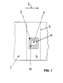
- Figure 1 shows the view of a broken piece of a web-shaped carrier material or substrate material 1.
- the web of this material 1 is in the conveying direction 2 in Figures 1 to 4 of promoted intermittently to the left to the right.
- two score lines are indicated, which are transverse to the Conveying direction 2 of the substrate material and a part of the blank of the subsequent packaging represent.
- the top wall 4 of the package are formed, in the later the opening device and so that the hole 5 are arranged.
- the pouring hole 5 is obtained by introducing the punched cut 6 in the substrate material.
- the punched cut 6 is indicated by the two dashed lines which differs through the coated substrate material but not through the two go through outer layers.
- the punched cut 6 also passes through the externally applied patches of the plastic film 7 therethrough.
- the outside of the later beverage package of this particular embodiment to think in the direction of the viewer on the figures above the substrate material 1 and in the cross-sectional view of the substrate material 1 of Figure 5 below; the inside So in the figures 2, 3 and 5 above and in the plan view of Figures 1 and 2 behind the aborted Share.
- sealing unit is the stained Plastic film 7 sealed before punching out of the hole 5, but in the example 1 in a conventional manner, in which a sealing plate, not shown, with smoother planar surface is shown as well as the counter-jaw 9 of the sealing unit 8 in This has the consequence that the entire hatched in Figure 1 area of the plastic film. 7 brought by the sealing to the softening temperature and the punching cut 6 (in in FIG 1, not shown) frayed and provided with fibrous supernatants.
- hole 5 can repeatedly cause leaks in the area of the pouring opening come. If you ignore the non-hatched area of the hole 5 in Figure 1 can be seen, one recognizes the square sealing surface 10, which is practically below the entire plastic film 7 is located.
- FIG. 1 In order to avoid the disadvantages associated therewith, that in FIG Substrate material 1 arranged sealing plate 11, which supported according to arrow 12 from below, stored and fixed, groove-like recessed areas 13 and adjacent raised areas 14. You go assume that the raised areas 14 are formed by standing during the milling process, then you can in the production of the sealing plate at selected locations, the recessed areas 13 mill out with the desired width to form a pattern.
- the width of the recessed areas 13 is about 2 to 20 mm, preferably 5 to 15 mm, and the recess creates a height difference from 0.5 to 4 mm, preferably 1.5 to 3 mm and most preferably 2 mm.
- the teflon coating is then so applied that it affects both the sublime and the recessed areas 13, 14 is, as shown in Figure 2 but not shown.
- the line of the punched cut 6 runs approximately after a circle, so that the pattern of a Circle results.
- This circular pattern is not only followed by the punching knife 15 and thus also the Line of the punched cut 6, but also the recessed areas 13.
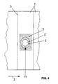
- the web-shaped substrate material 1 extends through both the sealing unit 8 of FIG. 2 and the punching unit 16 through and is continuously moved intermittently in the conveying direction 2.
- the plastic film 7 in the form of the outer patch is indicated in FIG. 2 by a line in the region of the sealing unit 8 below the Material 1 shown because the plastic film 7 are sealed to the outside of the material 1 should.
- FIG. 5 schematically shows a broken cross-section through the generally designated 1 Substrate material.
- the substrate sheet 22 in this embodiment is a board web and as a relatively thick web about in the middle with a hatching from top left to shown at the bottom right. Down from this middle panel 22, the outer layers are laid up, up the inner layers, considering the later packaging.
- An aluminum layer 23 is placed on the inside and an aluminized layer 24 on the outside, both by a cross hatching are shown. Outward then follows the print layer 25 with a hatching two phase-shifted sinusoidal lines.
- packaging externally to be provided with a pressure and if this on an aluminised Layer 24 in the form of the pressure layer 25 applies, then you can as in this particular embodiment achieve a gloss effect.
- a plastic layer preferably made of Polyethylene (PE). This is designated on both sides with 26 and practically not with a hatching Mistake.
- the inner one Polyethylene layer 28 is by a hatching with alternating lines from the bottom left to marked top right and intermediate points.
Abstract
Description
Die Erfindung betrifft eine Siegeleinheit zum Aufbringen einer Kunststoffolie auf ein flächiges Substratmaterial mittels Wärme und Druck mit einer Siegelplatte mit aktiver Oberfläche und einem relativ zu dieser bewegbaren Gegenbacken, wobei der Siegeleinheit eine Stanzeinheit mit Stanzmesser und Gegenplatte zum nachfolgenden Einbringen von Stanzschnitten an ausgewählten Stellen in das flächige Substratmaterial im Bereich der aufgebrachten Kunststoffolie nachgeschaltet ist.The invention relates to a sealing unit for applying a plastic film to a flat substrate material by means of heat and pressure with a sealing plate with active surface and a relative to this movable counter-jaws, wherein the sealing unit is a punching unit with punching knife and counter plate for the subsequent introduction of punch cuts at selected locations in the planar substrate material is connected downstream in the region of the applied plastic film.
Siegeleinheiten der vorstehend genannten Art sind in der Praxis von Verpackungsherstellern bekannt. Bei einem Beispiel ist eine Füllmaschine zum Herstellen und Füllen einer Flüssigkeitspackung bekannt, die aus einem Schlauch aus Packungsmaterial fortlaufend unter Befüllen und Verschließen hergestellt wird. Das Packungsmaterial ist bei diesem bekannten Beispiel ein mit Kunststoff beschichtetes, flächiges Trägermaterial, wobei Papier oder Karton als Trägermaterial eingesetzt wird. Öffnungsvorrichtungen dieser bekannten Packungen bestehen aus einem Loch durch das flächige Substratmaterial, wobei das Loch auf der Innenseite der Packung mit einem Kunststoffilm und auf der Außenseite mit einer Aufreißlasche verschlossen ist. Aufreißlasche und Kunststoffolie sind miteinander verschweißt, so daß beim Aufreißen der Aufreißlasche zum Öffnen der Packung der Bereich innerhalb des ausgestanzten Loches der inneren Kunststoffolie unter Bildung der Ausgießöffnung mit herausgerissen wird.Sealing units of the aforementioned type are known in the practice of packaging manufacturers. In one example, a filling machine is for making and filling a liquid package known from a tube of packing material continuously under filling and closing will be produced. The packing material in this known example is a plastic-coated, flat carrier material, paper or cardboard is used as a carrier material. Opening devices of these known packages consist of a hole through the surface Substrate material, with the hole on the inside of the pack with a plastic film and on the outside is closed with a tear tab. Tear tab and plastic film are together welded so that when tearing the tear tab to open the pack of the area within the punched hole of the inner plastic film to form the pouring opening being torn out with.
Früher hatte man die Aufreißlasche auf die äußere Kunststoffolie der Packung über das Loch direkt aufgeschweißt. Es hat sich dann mit Nachteil beim Aufreißen der Aufreißlasche gezeigt, daß die äußere Kunststoffolie fleckenförmig derart mit abgerissen wurde, daß man außen teilweise den beschichteten, bedruckten Karton, teilweise den bloßen Karton und teilweise Kunststoffetzen sah, die für den Endverbraucher beim Ansetzen der Packung zum Trinken ein schlechtes Mundgefühl erzeugten.Previously, you had the pull tab on the outer plastic film of the pack directly over the hole welded. It has then proved to be a disadvantage when tearing open the tear tab that the outer plastic film was stained with demolished so that outside partially coated, printed cardboard, partly the bare cardboard and partially plastic nets saw the created a poor mouthfeel for the end user when putting the pack on to drink.
Deshalb ist man schon dazu übergegangen, einen weiteren Kunststoffilm im Bereich des späteren Loches, dieses mit Abstand umgebend, auf die äußere Kunststoffschicht der Packung aufzusiegeln. Bei diesem Kunststoffilm oder der Kunststoffolie, die in englischsprachigen Fachkreisen prepatch genannt wird, handelt es sich um eine sogenannte OPP-Folie, die durchsichtig ist und sich pakkungsseitig nach unten gut auf die auf dem Trägermaterial aufliegende Kunststoffschicht aufbringen läßt und sich mit dieser gut verbindet, während sie nach außen hin zu der Aufreißlasche nur schälfähige schwache Verbindungskräfte entwickelt, insbesondere dann, wenn die Aufreißlasche ein mit Polyethylen (PE) beschichtetes Aluminium ist. Das flächige Substratmaterial wird mitsamt dieser aufgebrachten Kunststoff- oder Prepatch-Folie aus OPP-Film durchgestanzt. Wird danach die Aufreißlasche zum Öffnen der Packung entfernt, dann entstehen mit Vorteil nicht mehr die fleckenförmigen kleinen Bereiche mit bloßem Karton, beschichtetem Karton und Kunststoffetzen. Vielmehr ergibt sich jetzt durch das Aufbringen dieser Prepatch-Kunststoffolie, dieses Kunststoffflickens oder -ausschnittes für den Endverbraucher, wenn er die Flüssigkeit aus der Packung trinkt, ein gutes Mundgefühl.Therefore, one has already gone over to another plastic film in the area of the later Surround the hole with a gap, seal it on the outer plastic layer of the package. In this plastic film or plastic film prepatch in English-speaking professional circles is called, it is a so-called OPP film, which is transparent and pakkungsseitig Apply well to the plastic layer resting on the substrate leaves and connects with this well, while she outwardly peel to the pull-tab weak connection forces developed, especially if the tear tab with a Polyethylene (PE) coated aluminum is. The flat substrate material is together with this applied plastic or prepatch film punched out of OPP film. After that, the tear tab removed to open the pack, then arise no longer the spot-shaped small areas with bare cardboard, coated cardboard and plastic nets. Much more Now results from the application of this prepatch plastic film, this plastic or cut-out for the end user, if he drinks the liquid from the pack, a good one Mouthfeel.
Bei der Herstellung solcher Packungen mit dieser Art von flächigem Substratmaterial wird eine Siegeleinheit der eingangs genannten Art verwendet, um den Flecken oder die Kunststoffolie auf die spätere Außenseite des Substratmaterials aufzusiegeln, wobei danach sogleich die beschriebene Durchstanzung des gesamten Substratmaterials unter Bildung des Ausgießloches erfolgt. Deshalb ist der Siegeleinheit eine Stanzeinheit nachgeschaltet, in welcher ein entsprechend geformtes Stanzmesser durch das gesamte Substratmaterial mit den verschiedenen Kunststoffschichten und -folien hindurchgedrückt wird.In the manufacture of such packages with this type of sheet substrate material is a sealing unit of the type mentioned above to the stain or the plastic film on the later aufzusiegeln later outside of the substrate material, after which immediately described Punching the entire substrate material to form the Ausgießloches takes place. Therefore the sealing unit is followed by a punching unit, in which a correspondingly shaped Punching knife through the entire substrate material with the various plastic layers and Foils is pushed through.
Bei diesem Stanzvorgang ergibt sich nun beim Stand der Technik ein Problem dadurch, daß das Substratmaterial in der Siegeleinheit zum Aufbringen der Kunststoffolie auf Siegeltemperatur gebracht wird und kurz danach die für den Stanzschnitt ausgewählte Stelle in die Stanzeinheit geführt wird, so daß sich das Stanzmesser durch ein sich noch auf fast Siegeltemperatur befindliches Substratmaterial hindurchdrücken muß. Mit Nachteil fransen die Schnittlinien, welche durch das Stanzmesser erzeugt werden, mehr oder weniger stark aus, und es bleiben hier und da bloße Kunststoff-oder Kartonschnipsel oder -fasern fetzenartig hängen. Übersiegelt man derart mangelhaft geschnittene Öffnungen mit einer Aufreißlasche, dann ergeben sich hier und da Undichtigkeiten und unbrauchbare Packungen mit Leckage. Bei einem größeren Sammelgebinde von Packungen genügen ein bis drei undichte Packungen, um das gesamte Sammelgebinde unbrauchbar und unverkäuflich zu machen. Man hat daher die verschiedensten Versuche unternommen, diese Ausfransungen neben den Stanzmessern zu vermeiden. So hat man z.B. festgestellt, daß ein Stanzstempel mit kreisrundem Messer in sehr scharfem Neu-Zustand eine gewisse Zeit lang saubere Schnitte produziert. Nach 150 Betriebsstunden war das Stanzmesser aber so unscharf und abgenutzt, daß sich wieder die Ausfransungen ergaben. Mit weiterem Nachteil sammeln sich die überstehenden Fetzen, Fransen und Schnipsel im Abführschacht der Maschine, wodurch sich Verstopfungen ergaben. Der häufige Austausch von Stanzwerkzeugen stellt mit weiterem Nachteil eine für den Packungshersteller unerträgliche Kostensteigerung dar.In this punching process now arises in the prior art, a problem in that the Substrate material brought in the sealing unit for applying the plastic film to sealing temperature and shortly thereafter the selected location for the punching cut led into the punching unit is, so that the punching knife by a still close to sealing temperature befindliches substrate material must push through. At a disadvantage fringe the cutting lines, which by the punching knife produced, more or less strong, and it remains here and there mere plastic or Scrap cardboard or fibers like scraps. Sealed so poorly cut Openings with a pull-tab, then arise here and there leaks and unusable Packages with leakage. For a larger collection of packs suffice one to three leaking packages, around the entire collection container useless and unsalable close. It has therefore made a variety of attempts, these frays next to avoid the punching knives. So you have, for example found that a punch with circular Knife in very hot new condition produces clean cuts for a while. After 150 hours of operation, the punching knife was so fuzzy and worn that again the fraying resulted. With further disadvantage, the protruding rags, fringes accumulate and snippets in the discharge chute of the machine, resulting in blockages. The frequent Replacement of punching tools poses a further disadvantage for the pack manufacturer unbearable cost increase.
Der Erfindung liegt daher die Aufgabe zugrunde, die Siegeleinheit der eingangs beschriebenen Art so zu verbessern, daß an den Stanzschnitten nicht mehr Fasern, weder aus dem Trägermaterial noch aus dem Kunststoff, herausgerissen werden, sondern saubere Schnitte ohne Überstände entstehen. The invention is therefore based on the object, the sealing unit of the type described above to improve so that no more fibers on the punch cuts, neither from the substrate still being torn out of the plastic, but creating clean cuts without any protrusions.
Die Lösung dieser Aufgabe gelingt erfindungsgemäß dadurch, daß die Siegelplatte der Siegeleinheit an ihrer aktiven, den Gegenbacken zugewandten Oberfläche erhabene und vertiefte Bereiche hat und die Lage der vertieften Bereiche in der Siegelplatte der Lage des/der Stanzmesser/s entspricht, so daß der Stanzschnitt an den ausgewählten Stellen dort in dem Substratmaterial zu liegen kommt, wo infolge der vertieften Bereiche der Siegelplatte nahezu keine Erwärmung des Substratmaterials mit seinen Beschichtungen erfolgte. Man muß zunächst davon ausgehen, daß mit der speziell ausgestalteten Siegelplatte mit den erhabenen und vertieften Bereichen in deren aktiver Oberfläche die Kunststoffolie in einem größeren Oberflächenbereich des Substratmaterials aufgesiegelt wird, wo nachfolgend in der Stanzeinheit Stanzschnitte eingefügt werden sollen, und um diese herum. Diese Stanzschnitte gelingen mit besonders guter Qualität, d.h. als scharfe Schnitte ohne Ausfransungen, wenn das Stanzmesser durch kühlere Bereiche des Substratmaterials hindurchgetrieben wird. Wenn nun durch entsprechend geschickte Ausgestaltung der Siegelplatte in bestimmter Lage an ausgewählten Stellen vertiefte Bereiche vorgesehen werden, die in dem nachfolgenden Schritt in der Stanzeinheit dem Schneidvorgang angeboten werden, dann kann das Stanzmesser in Bereiche des Substratmaterials eindringen, welche nicht auf eine höhere Temperatur gebracht wurden, wie sie in anderen (erhabenen) Bereichen für das Aufbringen der Kunststoffolie an sich notwendig ist. Die Kunststoffolie kann also mit nützlicher Haftung auf das Substratmaterial aufgebracht werden, wobei (durch die vertieften Bereiche in der Siegelplatte) an ausgewählten Stellen kühlere Bereiche erzeugt werden, weil eben infolge der vertieften Bereiche der Siegelplatte dort nahezu keine Erwärmung erfolgte. Überraschenderweise hat sich gezeigt, daß auf diese Weise hergestellte Stanzschnitte scharf und ohne Ausfransungen auch dann hergestellt werden konnten, wenn das Schneidmesser viele Betriebsstunden im Betrieb war. Man ist durch die so ausgestaltete Siegelplatte mit den vertieften Bereichen überraschend in der Lage, Schnitte ohne Überstände auch bei beschichtetem Substratmaterial zu erzeugen.The solution of this object succeeds according to the invention in that the sealing plate of the sealing unit has raised and recessed areas on its active, counter-jaw-facing surface and the position of the recessed areas in the sealing plate corresponds to the position of the punching knife (s), so that the punched cut comes to rest there in the substrate material at the selected locations, where due to the recessed areas of the sealing plate almost no heating of the substrate material with his coatings. One must first assume that with the specially designed Sealing plate with the raised and recessed areas in the active surface of the Plastic film is sealed in a larger surface area of the substrate material, where Subsequently, in the punching unit punched cuts are to be inserted, and around them. These Die cuts succeed with particularly good quality, i. as sharp cuts without fraying, when the punch blade is driven through cooler areas of the substrate material. If now by appropriately skillful design of the sealing plate in a specific location on selected Provide in-depth areas to be provided in the subsequent step in the Punching unit are offered to the cutting process, then the punching knife in areas of the Substrate material penetrate, which were not brought to a higher temperature, as in other (raised) areas for the application of the plastic film itself is necessary. The Plastic film can therefore be applied with useful adhesion to the substrate material, wherein (through the recessed areas in the sealing plate) produces cooler areas at selected locations be, because just because of the recessed areas of the sealing plate there almost no warming took place. Surprisingly, it has been shown that punch cuts made in this way sharp and without fraying could be made even if the cutting blade many operating hours were in operation. One is through the thus configured sealing plate with the recessed Areas surprisingly able to cuts without supernatants even with coated substrate material to create.
Bei vorteilhafterer weiterer Ausgestaltung der Erfindung ist vorgesehen, daß in vorbestimmtem Abstand in Förderrichtung des Substratmaterials hinter der Siegeleinheit die Stanzeinheit angeordnet ist und eine koordinierte Ansteuerung beider Einheiten derart erfolgt, daß die ausgewählten Stellen in dem Substratmaterial in der Siegeleinheit über die vertieften Bereiche und danach in der Stanzeinheit unter das/die Stanzmesser zu liegen kommen. Die Siegeleinheit und die Stanzeinheit können zwei separate Geräte sein, die in der vorbeschriebenen Weise hintereinander derart angeordnet sind, daß das Substratmaterial, ob dies nun bogenförmig oder bahnförmig ist, zuerst in die Siegeleinheit und danach in die Stanzeinheit geführt wird. Die Zeit, die verstreicht, um das Substratmaterial von der Siegeleinheit in die Stanzeinheit zu fördern, beläuft sich zwischen einer Sekunde und drei Minuten und liegt bevorzugt bei zwei Sekunden. Wesentlich ist dabei, daß das Substratmaterial in der Siegeleinheit auf Siegeltemperatur erhitzt wird, das sind etwa 160°C, und daß nach der verstrichenen Zeit das Substratmaterial, wenn es in der Stanzeinheit bearbeitet wird, immer noch eine verhältnismäßig hohe Temperatur derart hat, daß die Kunststoffschicht oder -schichten bzw. - verhältnismäßig hohe Temperatur derart hat, daß die Kunststoffschicht oder -schichten bzw. -folien oder -filme immer noch verhältnismäßig weich sind. Dann nämlich gäbe es die vorstehend beschriebenen Ausfransungen, würde nicht die erfindungsgemäß ausgestaltete Siegelplatte verwendet.In a further advantageous embodiment of the invention, it is provided that at a predetermined distance arranged in the conveying direction of the substrate material behind the sealing unit, the punching unit and coordinated control of both units is such that the selected locations in the substrate material in the sealing unit over the recessed areas and then in the punching unit to be under the punching knife (s). The sealing unit and the punching unit can be two separate devices arranged one behind the other in the manner described above are that the substrate material, whether it is now arcuate or web-shaped, first in the sealing unit and then fed into the punching unit. The time that elapses to the substrate material from the sealing unit to the punching unit amounts to between one second and three Minutes and is preferably two seconds. It is essential that the substrate material in The sealing unit is heated to sealing temperature, that is about 160 ° C, and that after the the time the substrate material has been processed, while still being processed in the punching unit a relatively high temperature such that the plastic layer or layers or relatively high temperature has such that the plastic layer or layers or films or movies are still relatively soft. For then there would be those described above Fraying, would not use the inventively designed seal plate.
Wenn davon die Rede ist, daß das Substratmaterial in der Siegeleinheit über den vertieften Bereichen und danach in der Stanzeinheit unter dem Stanzmesser liegt, dann ist hier mit "über" und "unter" weniger eine örtliche Richtung gemeint, sondern die Position für den Eingriff (mit entsprechender Wirkung) der vertieften Bereiche einerseits und des Stanzmessers andererseits auf das Substratmaterial. Bei einer bevorzugten Ausführungsform kommt aber auch örtlich das Substratmaterial über die vertieften Bereiche zu liegen, d.h. die Siegelplatte nähert sich dem Substratmaterial von unten und drückt es nach oben gegen den Gegenbacken. Bei dieser oder bei einer anderen bevorzugten Ausführungsform kommt bevorzugt auch in der Stanzeinheit das Substratmaterial unter das bzw. die Stanzmesser zu liegen, d.h. das Stanzmesser bewegt sich von oberhalb des Substratmaterials durch dieses nach unten ein Stück weit hindurch, um die Stanzung zu erreichen. Bei anderen Maschinen könnten aber auch andere Bewegungsrichtungen der Siegelplatte und des Stanzmessers günstig sein.When it is said that the substrate material in the sealing unit over the recessed areas and then in the punching unit under the punching knife, then here is with "over" and "under" meant less a local direction, but the position for the intervention (with appropriate Effect) of the recessed areas on the one hand and the punching knife on the other hand on the substrate material. In a preferred embodiment, however, the substrate material also comes locally lie over the recessed areas, i. the sealing plate approaches the substrate material of down and push it up against the counter-jaw. In this or another preferred Embodiment preferably comes in the punching unit, the substrate material under the or the punching blades to lie, i. the punch blade moves from above the substrate material through this down a bit to reach the punching. For others Machines could also be other directions of movement of the sealing plate and the punching knife be cheap.
Ob nun die Siegeleinheit ein von der Stanzeinheit getrenntes Gerät ist, es müssen doch beide Einheiten koordiniert angesteuert werden, damit das Substratmaterial an den ausgewählten Stellen gegen eine Temperaturerhöhung verschont bleibt und das oder die Stanzmesser nur in diesen kalt gebliebenen Bereichen arbeiten, denn es soll vermieden werden, daß ein Stanzmesser in ein Substratmaterial mit hoher Temperatur eindringt. Deshalb ist die koordinierte Ansteuerung der Einheiten in erster Linie örtlich gemeint, damit die Position der Stanzmesser zu den kalt gebliebenen Bereichen in dem Substratmaterial richtig ausgerichtet wird. Erst in zweiter Linie handelt es sich bei der koordinierten Ansteuerung um eine zeitliche Beeinflussung. Bevorzugte Maschinen in der Praxis beinhalten aber beide Einheiten in einer Bearbeitungslinie, in welcher ein bahnförmiges, flächiges Substratmaterial intermittierend vorbewegt wird, zuerst in die Siegeleinheit und danach in die Stanzeinheit. Da allein schon wegen des Platzes in der Maschine die beiden Einheiten verhältnismäßig dicht beieinander liegen, ergibt sich auch, daß die Zeit zwischen dem Aufenthalt in der Siegeleinheit bis zu dem Aufenthalt in der Stanzeinheit zu kurz ist, als daß die durch die Siegelplatte erhöhte Temperatur des Substratmaterials sich von der einen Einheit zur anderen wesentlich abkühlt.Whether the sealing unit is a separate device from the punching unit, both have to Units are controlled in a coordinated manner, so that the substrate material at the selected locations is spared against an increase in temperature and the or the punching knife only in these cold work remaining areas, because it should be avoided that a punching knife in a substrate material penetrates with high temperature. Therefore, the coordinated control of the units primarily local, hence the position of the punching knife to the cold remained areas is properly aligned in the substrate material. Only secondarily, it is in the coordinated control by a temporal influence. Preferred machines in practice but contain both units in a processing line, in which a web-shaped, planar Substrate material is advanced intermittently, first in the sealing unit and then in the punching unit. Just because of the space in the machine, the two units relatively close to each other, it also follows that the time between the stay in the sealing unit is too short to stay in the punching unit, as that increased by the sealing plate Temperature of the substrate material is substantially cooled from one unit to another.
Erfindungsgemäß ist weiterhin vorgesehen, daß die vertieften Bereiche in der aktiven Oberfläche der Siegelplatte ein Muster bilden, welches eine Abbildung des Musters des/der Stanzmesser(s) der Stanzeinheit in gleichem Maßstab ist, so daß beide Muster deckungsgleich sind. Die Siegelplatte wirkt auf diese Weise wie eine Schablone, die auf dem Substratmaterial ein Temperaturmuster wie ein thermisches Bild erzeugt. Dieses Muster der vertieften Bereiche der Siegelplatte stimmt in den wesentlichen Maßen mit der Position des oder der Stanzmesser(s) überein - mit einer Ausnahme, die nachfolgend erläutert wird. Durch diese Übereinstimmung und Deckungsgleichheit der Muster in den beiden Einheiten wird sichergestellt, daß das Stanzmesser - in welcher Form, Lage oder Anordnung auch immer - das Substratmaterial nur in den kühl gebliebenen Bereichen stanzt. Dadurch sind mit Vorteil die Ausfransungen vermieden, so daß es in der Stanzeinheit der Maschine auch nicht die eingangs erwähnten nachteiligen Verstopfungen gibt.According to the invention it is further provided that the recessed areas in the active surface the sealing plate form a pattern which is an illustration of the pattern of the punching knife (s) of the Punching unit on the same scale, so that both patterns are congruent. The sealing plate acts in this way as a stencil, which on the substrate material a temperature pattern like generates a thermal image. This pattern of recessed areas of the seal plate is true substantially the same position as the punching knife (s) - with one exception, which will be explained below. By this coincidence and congruence of the patterns in The two units ensure that the punching knife - in what shape, position or arrangement however, the substrate material is only punched in the cool areas. Thereby are avoided with advantage the fraying, so that it is not in the punching unit of the machine mentioned in the beginning disadvantageous blockages.
Die vorstehend erwähnte Ausnahme besteht darin, daß ein Stanzmesser und auch seine Wirkung (der Schnitt) erheblich schmaler sind als die nutenartigen Vertiefungen oder Ausnehmungen in der Siegelplatte. Die Erfindung ist nämlich ferner dadurch gekennzeichnet, daß der vertiefte Bereich der Siegelplatte breiter ist als das Stanzmesser der Stanze, und die Stanzschnitte des Stanzmusters allseitig umgreift. Bei Einhaltung dieser Bedingung ist sichergestellt, daß das Stanzmesser oder das Stanzwerkzeug nur in kalte Bereiche des Substratmaterials schneidet und nirgends ein Ausfransen zu befürchten ist.The exception mentioned above is that a punching knife and also its effect (the section) are considerably narrower than the groove-like depressions or recesses in the Sealing plate. The invention is further characterized in that the recessed portion of the Sealing plate is wider than the punching knife of the punch, and the punched cuts of the punching pattern encompasses all sides. In compliance with this condition, it is ensured that the punching knife or the Punching tool cuts only in cold areas of the substrate material and no fraying anywhere is to be feared.
Wenn bei weiterer vorteilhafter Ausgestaltung der Erfindung die Siegelplatte aus Metall besteht und an ihrer aktiven Oberfläche zur Bildung der vertieften Bereiche ausgefräst ist, wobei vorzugsweise die aktive Oberfläche mit einem abriebfesten Kunststoffmaterial überzogen ist, läßt sich die Siegeleinheit und insbesondere die Siegelplatte einfach, preiswert und wirkungsvoll herstellen. Es hat sich als besonders günstig erwiesen, als Metall für die Siegelplatte Aluminium einzusetzen. Die vertieften Bereiche ergeben dann ein bestimmtes Muster von Nuten, wobei die erhabenen Bereiche selbstverständlich durch das stehengebliebene Material (z.B. Aluminium) gebildet werden.If, in a further advantageous embodiment of the invention, the sealing plate consists of metal and is milled on its active surface to form the recessed areas, preferably the active surface is coated with an abrasion-resistant plastic material, the sealing unit can be and in particular to make the sealing plate simple, inexpensive and effective. It has proved to be particularly favorable to use as metal for the sealing plate aluminum. The deepened Areas then give a particular pattern of grooves, with the raised areas of course formed by the remaining material (e.g., aluminum).
Für ein günstiges Versiegeln wird die aktive Oberfläche der Siegelplatte vorzugsweise mit dem erwähnten abriebfesten Kunststoffmaterial überzogen, bei welchem es sich bei vorteilhaften Ausführungsformen um Teflon handelt. Nach dem Aufbringen von Wärme und Druck mittels der Siegelplatte löst sich dann deren aktive Oberfläche leichter wieder von der Kunststoffolie, d.h. dem Ausschnitt oder dem angebrachten äußeren Flecken.For a favorable sealing, the active surface of the sealing plate is preferably with the mentioned coated abrasion-resistant plastic material, which is in advantageous embodiments Teflon. After application of heat and pressure by means of the sealing plate then dissolves their active surface easier again from the plastic film, i. the clipping or the attached outer patch.
Das Substratmaterial kann irgendein wenigstens teilweise mit Kunststoff beschichtetes Trägermaterial sein, z.B. Karton oder Papier. Das Problem mit dem Ausfransen oder dem Stanzen mit Fasern ergibt sich immer dann, wenn eine Kunststoffolie auf einem Trägermaterial bei einer Temperatur im Bereich der Erweichungstemperatur des Kunststoffes gestanzt werden soll. Bei dem Substratmaterial kann es sich um platten- oder bogenförmige Teile handeln.The substrate material may be any at least partially plastic coated substrate be, e.g. Cardboard or paper. The problem with fraying or punching with fibers arises whenever a plastic film on a substrate at a temperature in the Range of softening temperature of the plastic to be punched. In the substrate material it may be plate or arcuate parts.
Besonders bevorzugt ist es erfindungsgemäß aber, wenn das flächige Substratmaterial in Bahnform durch Antriebsmittel von der Siegeleinheit in die Stanzeinheit intermittierend bewegbar ist. Eine solche Vorrichtung, bei welcher beide Einheiten zusammengefaßt sind, wird in besonders zweckmäßiger Weise als Öffnungsaggregat für eine Füllmaschine verwendet, wobei dieses Öffnungsaggregat in Förderrichtung des bahnförmigen Substratmaterials vor der Füllmaschine vorgesehen wird.However, it is particularly preferred according to the invention if the flat substrate material is in web form is intermittently movable by drive means from the sealing unit into the punching unit. Such Device in which both units are combined, is particularly useful Used as an opening unit for a filling machine, this opening unit is provided in the conveying direction of the web-shaped substrate material in front of the filling machine.
So hat es sich z.B. erfindungsgemäß als günstig erwiesen, wenn die Siegeleinheit zu einem Öffnungsaggregat für eine Füllmaschine für Flüssigkeitspackungen gehört und das Substratmaterial eine mit mehreren Kunststoffschichten versehene Trägermaterialbahn mit Kerblinien zur Erzeugung einer Packung mit Aufreißlasche ist und das Muster der Stanzmesser ein Kreis ist. Es sind Flüssigkeitspackungen in Form ähnlich einem Quader hinlänglich bekannt. Es ist auch bekannt, solche Flüssigkeitspackungen aus mit Kunststoff beschichtetem Karton als Substratmaterial herzustellen, wobei aus der Kartonbahn, die intermittierend durch die Füllmaschine bewegt wird, letztlich die gefüllte und verschlossene Packung abgefördert wird. Diese Packung hat auch eine Ausgießöffnung, die aus einem im Oberboden der Packung eingefügten Loch besteht, welches von oben, der späteren Außenseite der Packung, durch eine Aufreißlasche verschlossen wird und vorzugsweise von innen durch eine weitere Kunststoffolie abgedichtet wird (Kantenschutz der Schnittlinien).So it has, for example According to the invention proved to be favorable when the sealing unit to an opening unit belongs to a liquid filling machine and the substrate material a carrier sheet provided with a plurality of plastic layers with score lines for production a pack with pull tab and the pattern of the punching knife is a circle. They are liquid packs in the form of a cuboid well known. It is also known, such To produce liquid packages of plastic-coated cardboard as a substrate material, from the cardboard web, which is moved intermittently through the filling machine, ultimately filled and sealed pack is carried away. This pack also has a pouring spout, which consists of a hole inserted in the topsoil of the pack, which from above, the later Outside of the pack, is closed by a pull tab and preferably by is sealed inside by another plastic film (edge protection of the cutting lines).
Eine vorgeschaltete Papiermaschine erzeugt die Bahn mit den Packungszuschnitten, wobei diese Bahn des Verpackungsmaterials als Träger den erwähnten Karton hat, der mit vorzugsweise mehreren Schichten abgedeckt ist. Dazu gehört z.B. eine Aluminiumschicht und auf diese aufgelegte Polyethylenschichten. Vor dem Aufsiegeln der Aufreißlasche auf der Außenseite und der Kunststoffolie (Polyethylen) auf der Innenseite der späteren Packung auf das Loch, bevor also diese beiden letzten Beschichtungen erfolgen, wird die mit den verschiedenen Beschichtungen versehene Trägermaterialbahn unter Bildung des Loches durchgestanzt, und bei einem kreisförmigen Loch ist dann das Muster des Stanzmessers entsprechend ein Kreis. Die beschichtete Trägermaterialbahn ist auch mit verschiedenen, an sich bekannten "Kerblinien" versehen, um aus dem mit dem flüssigen Inhalt gefüllten und dann durch Siegeln verschlossenen Schlauch die Packungen durch Falten zu formen. In diesen Packungsherstellungs- bzw. -füllmaschinen trat das eingangs erwähnte Problem der Undichtigkeit seit Jahren zutage, ohne daß man werkzeugseitig eine vernünftige Lösung anbieten konnte. Erst die Erfindung mit der speziell ausgestalteten Siegelplatte und den vertieften Bereichen, mit deren Hilfe die Schnittbereiche kalt belassen werden können, hat die Probleme zu voller Zufriedenheit gelöst. Es können jetzt Flüssigkeitspackungen in großer Stückzahl pro Zeiteinheit mit leistungsstarken Füllmaschinen hergestellt und in Sammelgebinden zusammengefaßt werden, ohne daß sich auch nur eine Packung mit Leckage zeigt.An upstream paper machine produces the web with the package blanks, these being Web of the packaging material as a carrier has the mentioned cardboard, preferably with a plurality of Layers is covered. This includes e.g. an aluminum layer and polyethylene layers applied to it. Before sealing the tear tab on the outside and the plastic film (Polyethylene) on the inside of the later pack on the hole, so before those last two Coatings done, is provided with the various coatings substrate sheet punched to form the hole, and in a circular hole is then the Pattern of the punching knife corresponding to a circle. The coated substrate sheet is also with various, known "score lines" provided to from the filled with the liquid content and then sealed by sealing tube to form the packs by folding. In These packing manufacturing and filling machines came the aforementioned problem of leakage for years, without a tool-wise solution could offer. Only the invention with the specially designed sealing plate and the recessed areas, with their Helping the cutting areas to be left cold has the problems to the fullest satisfaction solved. It can now liquid packs in large quantities per unit of time with powerful Filling machines are manufactured and summarized in collection batches without getting even just a package with leakage shows.
Weitere Vorteile, Merkmale und Anwendungsmöglichkeiten der Erfindung ergeben sich aus der folgenden Beschreibung einer bevorzugten Ausführungsform in Verbindung mit den anliegenden Zeichnungen. Bei diesen zeigen:
Figur 1- die Draufsicht auf ein abgebrochenes Stück eines bahnförmigen Substratmaterials in Form einer mit Kunststoff beschichteten Kartonbahn nach Anbringung des äußeren Kunststofffleckens auf herkömmliche Weise mit nachfolgendem Ausstanzen eines Loches,
Figur 2- in einer Querschnittsansicht links die Siegeleinheit und rechts die Stanzeinheit vor dem Stanzen bei einer erfindungsgemäßen Ausführungsform,
Figur 3- in gleicher
Querschnittsansicht wie Figur 2 die Stanzeinheit kurz nach dem Stanzen des Loches, Figur 4- eine ähnliche
Ansicht wie Figur 1, hier jedoch mit dem erfindungsgemäß hergestellten Produkt, bei welchem der von oben auf die beschichtete Kartonbahn aufgebrachte äußere Kunststoffflecken um das in der Mitte ausgestanzte Loch herum einen siegelfreien Ringbereich hat, und Figur 5- eine Querschnittsansicht eines bevorzugten Substratmaterials mit gestrichelt gezeigter Stanzlinie und schematisch dazwischen angeordneter Linie zur Veranschaulichung, daß die äußeren Schichten miteinander versiegelt sind.
- FIG. 1
- the top view of a broken piece of a web-shaped substrate material in the form of a plastic-coated board web after attachment of the outer plastic spill in a conventional manner with subsequent punching a hole,
- FIG. 2
- in a cross-sectional view on the left the sealing unit and on the right the punching unit before punching in an embodiment according to the invention,
- FIG. 3
- in the same cross-sectional view as Figure 2, the punching unit shortly after punching the hole,
- FIG. 4
- a view similar to Figure 1, but here with the product according to the invention, in which the applied from the top of the coated board web outer plastic patch around the hole punched in the middle has a seal-free ring area, and
- FIG. 5
- a cross-sectional view of a preferred substrate material with a broken line shown in phantom and schematically arranged therebetween line to illustrate that the outer layers are sealed together.
Figur 1 zeigt den Blick auf ein abgebrochenes Stück eines bahnförmigen Trägermaterials oder Substratmaterials
1. Die Bahn dieses Materials 1 wird in Förderrichtung 2 in den Figuren 1 bis 4 von
links nach rechts intermittierend gefördert. Mit 3 sind zwei Kerblinien angedeutet, die sich quer zur
Förderrichtung 2 des Substratmaterials erstrecken und einen Teil des Zuschnitts der späteren Verpackung
darstellen. In dieser schematischen Darstellung der Figuren soll durch die beiden Kerblinien
3 die Oberwand 4 der Verpackung gebildet werden, in der später die Öffnungsvorrichtung und
damit auch das Loch 5 angeordnet sind. Das Ausgießloch 5 ergibt sich durch Einbringen des Stanzschnittes
6 in das Substratmaterial. In Figur 5 ist der Stanzschnitt 6 durch die zwei gestrichelten Linien
veranschaulicht, welche durch das beschichtete Substratmaterial, nicht aber durch die beiden
äußeren Schichten hindurchgehen.Figure 1 shows the view of a broken piece of a web-shaped carrier material or
Der Stanzschnitt 6 geht aber auch durch den außen aufgebrachten Flecken der Kunststoffolie 7
hindurch. Dabei ist die Außenseite der späteren Getränkeverpackung dieser speziellen Ausführungsform
in Blickrichtung des Betrachters auf die Figuren oberhalb des Substratmaterials 1 zu denken
und in der Querschnittsdarstellung des Substratmaterials 1 der Figur 5 unten; die Innenseite
also in den Figuren 2, 3 und 5 oben und bei der Draufsicht der Figuren 1 und 2 hinter den abgebrochenen
Teilen. In einer erst in Figur 2 allgemein mit 8 bezeichneten Siegeleinheit wird die fleckenförmige
Kunststoffolie 7 vor dem Herausstanzen des Loches 5 aufgesiegelt, allerdings bei dem Beispiel
der Figur 1 in herkömmlicher Weise, bei welcher eine nicht dargestellte Siegelplatte mit glatter
ebener Oberfläche ebenso dargestellt zu denken ist wie der Gegenbacken 9 der Siegeleinheit 8 in
Figur 2. Dies hat zur Folge, daß der gesamte in Figur 1 schraffierte Bereich der Kunststoffolie 7
durch das Aufsiegeln auf die Erweichungstemperatur gebracht ist und der Stanzschnitt 6 (in in Figur
1 nicht dargestellter Weise) ausgefranst und mit faserigen Überständen versehen ist. Bei dem herkömmlich
hergestellten Loch 5 kann es also immer wieder zu Undichtigkeiten im Bereich der Ausgießöffnung
kommen. Wenn man in Figur 1 den schraffurfreien Bereich des Loches 5 unbeachtet
läßt, erkennt man die quadratische Siegelfläche 10, die sich praktisch unter der gesamten Kunststoffolie
7 befindet.However, the punched cut 6 also passes through the externally applied patches of the
Zur Vermeidung der damit in Verbindung stehenden Nachteile weist die in Figur 2 unterhalb des
Substratmaterials 1 angeordnete Siegelplatte 11, die gemäß Pfeil 12 von unten abgestützt, gelagert
und befestigt ist, nutenartig vertiefte Bereiche 13 und daneben erhabene Bereiche 14 auf. Geht man
davon aus, daß die erhabenen Bereiche 14 beim Fräsvorgang durch Stehenlassen gebildet werden,
dann kann man bei der Herstellung der Siegelplatte an ausgewählten Stellen die vertieften Bereiche
13 mit gewünschter Breite zur Bildung eines Musters herausfräsen. Die Breite der vertieften Bereiche
13 beträgt etwa 2 bis 20 mm, vorzugsweise 5 bis 15 mm, und die Vertiefung schafft eine Höhendifferenz
von 0,5 bis 4 mm, vorzugsweise 1,5 bis 3 mm und ganz bevorzugt 2 mm. Die TeflonBeschichtung
wird danach so aufgebracht, daß sie sich sowohl auf den erhabenen als auch auf den
vertieften Bereichen 13, 14 befindet, wie in Figur 2 aber nicht dargestellt ist. Im Falle eines Ausgießloches
5 verläuft die Linie des Stanzschnittes 6 etwa nach einem Kreis, so daß sich das Muster eines
Kreises ergibt. Diesem Kreismuster folgen nicht nur das Stanzmesser 15 und damit auch die
Linie des Stanzschnittes 6, sondern auch die vertieften Bereiche 13. Das bahnförmige Substratmaterial
1 erstreckt sich sowohl durch die Siegeleinheit 8 der Figur 2 als auch durch die Stanzeinheit 16
hindurch und wird fortlaufend intermittierend in Förderrichtung 2 bewegt. Die Kunststoffolie 7 in Form
des äußeren Fleckens ist in Figur 2 durch einen Strich im Bereich der Siegeleinheit 8 unterhalb des
Materials 1 gezeigt, weil die Kunststoffolie 7 auf die Außenseite des Materials 1 aufgesiegelt werden
soll. Drückt man nun den beweglichen Gegenbacken 9 auf die Siegelplatte 11 mit dazwischen eingelegtem
Substratmaterial 1 mit Kunststoffolie 7, dann erwärmen sich die grau angelegten Bereiche
in dem Material 1, denn diese stehen den erhabenen Bereichen 14 der Siegelplatte 11 gegenüber.
Dazwischen ergeben sich die kalten Bereiche 17 in der Bahn des Substratmaterials 1.In order to avoid the disadvantages associated therewith, that in
Überträgt man diesen Gedanken auf die Darstellung der Figur 4, dann erkennt man einen fast kreisförmigen
Ringbereich mit einer Schraffur von links oben nach rechts unten, welches den kalten Bereich
17 darstellt. Dabei ist aber zu berücksichtigen, daß vor dem Ausstanzen des Loches 5 dieser
kalte Bereich 17 sich auch über die Stanzschnittlinie 6 hinaus ein Stück weit nach innen erstreckt,
denn der Stanzschnitt 6 muß auf beiden Seiten vollständig von kalten Bereichen 17 umgeben sein. If one transfers this idea to the representation of Figure 4, then one recognizes an almost circular one
Ring area with a hatching from top left to bottom right, which is the
In der Darstellung der Figur 2 sieht man dies deutlich daran, daß sich die kalten Bereiche 17 in dem
bahnförmigen Substratmaterial 1 fast mittig unter dem Stanzmesser 15 befinden. Wird das in diesem
Ausführungsbeispiel als Stempel ausgebildete Stanzmesser 15 in Richtung des Pfeiles 18 nach
unten durch das Substratmaterial 1 hindurchbewegt, dann wird nicht nur der Stanzschnitt 6 gelegt,
sondern man sieht auch den heißen Siegelbereich 19 der herausgestanzten Kreisscheibe 20 mit der
unten anhaftenden Kunststoffolie 7, und seitlich neben den beiden äußeren Stanzschnitten 6 schließen
sich wieder die in Figur 3 dargestellten weißen kalten Bereiche 17 im Trägermaterial 1 an. Auf
beiden Seiten des Stanzschnittes 6 liegen also Teile der kalten Bereiche 17 mit der Folge, daß der
Stanzschnitt 6 ganz durch kaltes Material hindurchgeführt wurde. Dadurch erreicht man den faserfreien
und fransenfreien, sauberen Stanzschnitt 6 in gewünschtem Muster, bei der hier gezeigten
Ausführungsform etwa in Form eines Kreises.In the illustration of Figure 2, this is clearly seen that the
In Figur 3 wird der Stempel mit dem Stanzmesser 15 dann in entgegengesetzter Richtung zum Bewegungspfeil
18 wieder nach oben gezogen, und es liegt dann der in Figur 4 in Draufsicht gezeigte
Zustand vor.In FIG. 3, the punch with the punching
Es versteht sich, daß die Gegenplatte 21 der Stanzeinheit 16 an ausgewählten Stellen die kreisförmige
Begrenzung des Loches aufweist, um mit dem Stanzmesser 15 eine Scherwirkung zum Ausstanzen
des Loches 5 zu erreichen.It is understood that the counter-plate 21 of the punching
Der Abstand in Förderrichtung 2 der Stanzeinheit 16 von der Siegeleinheit 8 ergibt sich gemäß Figur
2 aus dem senkrechten Abstand der Pfeile 9 und 18, die etwa in der jeweiligen Mittellinie der Einheit
liegen.The distance in the conveying
In Figur 5 sieht man schematisch einen abgebrochenen Querschnitt durch das allgemein mit 1 bezeichnete
Substratmaterial. Die Trägermaterialbahn 22 ist bei dieser Ausführungsform eine Kartonbahn
und als verhältnismäßig dicke Bahn etwa in der Mitte mit einer Schraffur von links oben nach
rechts unten dargestellt. Nach unten von dieser mittleren Bahn 22 sind die äußeren Schichten aufgelegt,
nach oben die inneren Schichten, wenn man die spätere Verpackung betrachtet. Eine Aluminiumschicht
23 ist innen und eine aluminiumbedampfte Schicht 24 außen aufgelegt, die beide durch
eine Kreuzschraffur dargestellt sind. Nach außen folgt dann die Druckschicht 25 mit einer Schraffurdarstellung
zweier phasenverschoben zueinander verlaufender Sinuslinien. Es ist bekannt, Verpakkungen
außen mit einem Druck zu versehen, und wenn man diesen auf eine aluminiumbedampfte
Schicht 24 in Form der Druckschicht 25 aufbringt, dann kann man wie bei dieser speziellen Ausführungsform
einen Glanzeffekt erreichen. Zum Schutz wird dann außen auf die Druckschicht 25 und
innen auf die Aluminiumschicht 23 jeweils eine Kunststoffschicht aufgebracht, vorzugsweise aus
Polyethylen (PE). Diese ist auf beiden Seiten mit 26 bezeichnet und praktisch nicht mit einer Schraffur
versehen. FIG. 5 schematically shows a broken cross-section through the generally designated 1
Substrate material. The
Bis zu dieser PE-Schicht 26 handelt es sich um das bahnförmige Substratmaterial 1. Auf dieses wird
danach in der Siegeleinheit 8 die fleckenförmige Kunststoffolie 7 mit Hilfe der speziellen Siegelplatte
14 aufgesiegelt. Der aufgesiegelte Zustand ist in Figur 5 gezeigt, und diese Kunststoffolie 7 ist mit
enger kurzer Schraffur von links oben nach rechts unten gekennzeichnet.Up to this
In diesem Zustand, d.h. Substratmaterial 1 plus Kunststoffolie 7, erfolgt die Stanzung, so daß sich
der als gestrichelte Linien dargestellte Stanzschnitt 6 ergibt. Das genannte Substratmaterial mit dem
Kunststoffflecken 7 weist nun ein Loch auf, welches später als Ausgießloch 5 verwendet werden
kann. Zuvor aber muß die Packung dicht sein. Dafür wird von außen ein Aufreißstreifen 27 aufgesiegelt,
der in Figur 5 eine Schraffur von links unten nach rechts oben zeigt. Es handelt sich bei dieser
Aufreißlasche 27 um mit Polyethylen beschichtetes Aluminium, wie an sich bekannt ist. Auf der
gegenüberliegenden Innenseite, in der Darstellung der Figur 5 also oben, wird eine weitere Polyethylenschicht
über das Loch aufgesiegelt und mit der Aufreißlasche 27 versiegelt. Die letztgenannte
Verbindung durch Versiegeln zwischen der inneren Polyethylenschicht 28 und der äußeren Aufreißlasche
27 ist in Figur 5 durch eine durchgezogene Linie 29 mit zwei Endpunkten dargestellt.
Reißt nämlich der Endverbraucher die Aufreißlasche 27 von der gefüllten Getränkepackung ab,
dann reißt er auch die innere Polyethylenschicht 28 im Bereich des Ausgießloches 5 auf, um Zugang
zu dem Packungsinhalt zu bekommen und das Ausgießloch 5 benutzen zu können. Die innere
Polyethylenschicht 28 ist durch eine Schraffur mit abwechselnden Strichen von links unten nach
rechts oben und dazwischenliegenden Punkten gekennzeichnet.In this condition, i.
Claims (7)
dadurch gekennzeichnet, daß die Siegelplatte (11) der Siegeleinheit (8) an ihrer aktiven, dem Gegenbacken (9) zugewandten Oberfläche erhabene (14) und vertiefte Bereiche (13) hat und die Lage der vertieften Bereiche (13) in der Siegelplatte (11) der Lage des/der Stanzmesser/s (15) entspricht, so daß der/die Stanzschnitt/e (6) an den ausgewählten Stellen dort in dem Substratmaterial (1) zu liegen kommt, wo infolge der vertieften Bereiche (13) der Siegelplatte (11) nahezu keine Erwärmung des Substratmaterials (1) mit seinen Beschichtungen erfolgte.Sealing unit (8) for applying a plastic film (7) to a sheet-like substrate material (1) by means of heat and pressure with a sealing plate (11) having an active surface and a relative to this movable counter-jaw (9), wherein the sealing unit (8) is a punching unit (16) with punching knife (15) and counter-plate (21) for subsequent introduction of punched cuts (6) at selected locations in the sheet-like substrate material (1) in the region of the applied plastic film (7) is connected downstream,
characterized in that the sealing plate (11) of the sealing unit (8) on its active, the counterjaw (9) facing surface raised (14) and recessed areas (13) and the position of the recessed areas (13) in the sealing plate (11 ) corresponds to the position of the punching blade (s) (15), so that the punching cut (s) (6) comes to rest at the selected locations in the substrate material (1) where, due to the recessed areas (13) of the sealing plate (11) there was almost no heating of the substrate material (1) with its coatings.
Priority Applications (1)
| Application Number | Priority Date | Filing Date | Title |
|---|---|---|---|
| PL05102334T PL1584448T3 (en) | 2004-04-08 | 2005-03-23 | Sealing device for applying a plastic foil on a substrate material. |
Applications Claiming Priority (2)
| Application Number | Priority Date | Filing Date | Title |
|---|---|---|---|
| DE102004017429 | 2004-04-08 | ||
| DE102004017429A DE102004017429A1 (en) | 2004-04-08 | 2004-04-08 | Sealing unit for applying a plastic film to a substrate material |
Publications (2)
| Publication Number | Publication Date |
|---|---|
| EP1584448A1 true EP1584448A1 (en) | 2005-10-12 |
| EP1584448B1 EP1584448B1 (en) | 2008-05-14 |
Family
ID=34895532
Family Applications (1)
| Application Number | Title | Priority Date | Filing Date |
|---|---|---|---|
| EP05102334A Not-in-force EP1584448B1 (en) | 2004-04-08 | 2005-03-23 | Sealing device for applying a plastic foil on a substrate material. |
Country Status (11)
| Country | Link |
|---|---|
| US (1) | US7422045B2 (en) |
| EP (1) | EP1584448B1 (en) |
| JP (1) | JP4762595B2 (en) |
| CN (1) | CN100509569C (en) |
| AT (1) | ATE395179T1 (en) |
| AU (1) | AU2005201093B2 (en) |
| BR (1) | BRPI0501173A (en) |
| DE (2) | DE102004017429A1 (en) |
| ES (1) | ES2306008T3 (en) |
| MX (1) | MXPA05003443A (en) |
| PL (1) | PL1584448T3 (en) |
Cited By (1)
| Publication number | Priority date | Publication date | Assignee | Title |
|---|---|---|---|---|
| CN113021921A (en) * | 2019-12-09 | 2021-06-25 | 苏州运宏电子有限公司 | Manufacturing method of inner shrinking rubber reinforced steel sheet |
Families Citing this family (7)
| Publication number | Priority date | Publication date | Assignee | Title |
|---|---|---|---|---|
| MY159095A (en) * | 2007-10-31 | 2016-12-15 | Novartis Ag | Packaging seal plate having a shaped face |
| US7614202B2 (en) * | 2007-11-27 | 2009-11-10 | Atlas Vac Machine Co., Llc | Sealer and interchangeable tooling therefor |
| CN101898434B (en) * | 2009-05-27 | 2013-01-02 | 比亚迪股份有限公司 | Preparation method of die-cutting product |
| CN103633103B (en) * | 2012-08-27 | 2018-06-01 | 秦皇岛柏泰六淳自动化设备有限公司 | The pressure head of Image Sensor encapsulation |
| US9119450B2 (en) | 2012-12-21 | 2015-09-01 | Novartis Ag | Contact lens package |
| CN106376227A (en) * | 2015-07-21 | 2017-02-01 | 上海徕木电子股份有限公司 | Manufacturing process for insulation shielding case |
| US11034474B2 (en) | 2016-10-31 | 2021-06-15 | Ross Industries, Inc. | Dual purpose seal head assembly, tray sealing system, and method therefor |
Citations (6)
| Publication number | Priority date | Publication date | Assignee | Title |
|---|---|---|---|---|
| US5452849A (en) * | 1988-05-19 | 1995-09-26 | Morgan Adhesives Co. | Easy open tab sealer for packages |
| DE4432718A1 (en) * | 1994-09-14 | 1996-03-21 | Tetra Laval Holdings & Finance | Plastic package with tear-off strap and mfg. tool |
| US5766385A (en) * | 1995-12-06 | 1998-06-16 | Velcro Industries B.V. | Separable fastener having die-cut protective cover with pull tab and method of making same |
| EP0848937A2 (en) * | 1996-12-21 | 1998-06-24 | Sunkyong Industries Co. | Apparatus for manufacturing medicinal pathes for percutaneous administration |
| EP1086899A1 (en) * | 1999-09-24 | 2001-03-28 | Molins Plc | Method and apparatus for producing bags having a recloseable fastener |
| US6649011B1 (en) * | 1998-08-20 | 2003-11-18 | Lts Lohmann Therapie-Systeme Ag | Method for producing adhesive blanks form an endless band and blanks obtained according to said method |
Family Cites Families (14)
| Publication number | Priority date | Publication date | Assignee | Title |
|---|---|---|---|---|
| US2467572A (en) * | 1946-02-08 | 1949-04-19 | Leaf Mfg Corp | Method and means for producing artificial flower leaves |
| US2822029A (en) * | 1955-07-08 | 1958-02-04 | Standard Safety Equipment Co | Dielectric heat sealing apparatus |
| BE644300A (en) | 1963-02-25 | 1900-01-01 | ||
| US3505152A (en) * | 1966-07-15 | 1970-04-07 | Anchor Hocking Glass Corp | Closure cap liner and method of making |
| US4735675A (en) * | 1982-04-26 | 1988-04-05 | Athena Controls Inc. | Heating device for sealing material to effect different bond strengths |
| JPS60134761U (en) * | 1984-02-17 | 1985-09-07 | 東洋製罐株式会社 | Packaging container with straw tab |
| JPS6239426A (en) * | 1985-08-15 | 1987-02-20 | オリヒロ株式会社 | Bagging lateral sealing mechanism |
| JPH07106728B2 (en) * | 1986-07-04 | 1995-11-15 | 四国化工機株式会社 | Container mouthpiece sealing device |
| AU3152795A (en) * | 1994-07-28 | 1996-02-22 | Victor B. Kley | Scanning probe microscope assembly |
| US6252226B1 (en) * | 1994-07-28 | 2001-06-26 | General Nanotechnology, L.L.C. | Nanometer scale data storage device and associated positioning system |
| US6337479B1 (en) * | 1994-07-28 | 2002-01-08 | Victor B. Kley | Object inspection and/or modification system and method |
| US6339217B1 (en) * | 1995-07-28 | 2002-01-15 | General Nanotechnology Llc | Scanning probe microscope assembly and method for making spectrophotometric, near-field, and scanning probe measurements |
| DE19503458B4 (en) * | 1995-02-03 | 2007-10-31 | Rüdiger Haaga GmbH | Device for closing a filling opening |
| JP2003011908A (en) * | 2001-06-26 | 2003-01-15 | Nihon Tetra Pak Kk | Lip sticking apparatus |
-
2004
- 2004-04-08 DE DE102004017429A patent/DE102004017429A1/en not_active Ceased
-
2005
- 2005-03-11 AU AU2005201093A patent/AU2005201093B2/en not_active Ceased
- 2005-03-21 US US11/084,961 patent/US7422045B2/en not_active Expired - Fee Related
- 2005-03-23 PL PL05102334T patent/PL1584448T3/en unknown
- 2005-03-23 ES ES05102334T patent/ES2306008T3/en active Active
- 2005-03-23 AT AT05102334T patent/ATE395179T1/en not_active IP Right Cessation
- 2005-03-23 EP EP05102334A patent/EP1584448B1/en not_active Not-in-force
- 2005-03-23 DE DE502005004072T patent/DE502005004072D1/en active Active
- 2005-03-30 BR BR0501173-6A patent/BRPI0501173A/en active Search and Examination
- 2005-03-31 MX MXPA05003443A patent/MXPA05003443A/en active IP Right Grant
- 2005-04-08 JP JP2005111617A patent/JP4762595B2/en not_active Expired - Fee Related
- 2005-04-08 CN CNB2005100650759A patent/CN100509569C/en not_active Expired - Fee Related
Patent Citations (6)
| Publication number | Priority date | Publication date | Assignee | Title |
|---|---|---|---|---|
| US5452849A (en) * | 1988-05-19 | 1995-09-26 | Morgan Adhesives Co. | Easy open tab sealer for packages |
| DE4432718A1 (en) * | 1994-09-14 | 1996-03-21 | Tetra Laval Holdings & Finance | Plastic package with tear-off strap and mfg. tool |
| US5766385A (en) * | 1995-12-06 | 1998-06-16 | Velcro Industries B.V. | Separable fastener having die-cut protective cover with pull tab and method of making same |
| EP0848937A2 (en) * | 1996-12-21 | 1998-06-24 | Sunkyong Industries Co. | Apparatus for manufacturing medicinal pathes for percutaneous administration |
| US6649011B1 (en) * | 1998-08-20 | 2003-11-18 | Lts Lohmann Therapie-Systeme Ag | Method for producing adhesive blanks form an endless band and blanks obtained according to said method |
| EP1086899A1 (en) * | 1999-09-24 | 2001-03-28 | Molins Plc | Method and apparatus for producing bags having a recloseable fastener |
Cited By (1)
| Publication number | Priority date | Publication date | Assignee | Title |
|---|---|---|---|---|
| CN113021921A (en) * | 2019-12-09 | 2021-06-25 | 苏州运宏电子有限公司 | Manufacturing method of inner shrinking rubber reinforced steel sheet |
Also Published As
| Publication number | Publication date |
|---|---|
| MXPA05003443A (en) | 2005-10-18 |
| EP1584448B1 (en) | 2008-05-14 |
| DE102004017429A1 (en) | 2005-10-27 |
| US7422045B2 (en) | 2008-09-09 |
| CN100509569C (en) | 2009-07-08 |
| AU2005201093B2 (en) | 2010-09-23 |
| PL1584448T3 (en) | 2008-09-30 |
| US20050223676A1 (en) | 2005-10-13 |
| JP4762595B2 (en) | 2011-08-31 |
| DE502005004072D1 (en) | 2008-06-26 |
| CN1680172A (en) | 2005-10-12 |
| AU2005201093A1 (en) | 2005-10-27 |
| ATE395179T1 (en) | 2008-05-15 |
| JP2005298067A (en) | 2005-10-27 |
| ES2306008T3 (en) | 2008-11-01 |
| BRPI0501173A (en) | 2005-11-16 |
Similar Documents
| Publication | Publication Date | Title |
|---|---|---|
| EP1584448B1 (en) | Sealing device for applying a plastic foil on a substrate material. | |
| DE60219109T2 (en) | Method and device for thermoforming, filling and sealing of undercut containers | |
| DE3442341A1 (en) | TRAY FOR ACCOMPANYING FOODSTUFFS AND METHOD AND DEVICE FOR THE PRODUCTION THEREOF | |
| DE2946739A1 (en) | LAYERED LAMINATED PACKAGING MATERIAL AND METHOD FOR THE PRODUCTION THEREOF | |
| DE102006017258A1 (en) | Method for producing a packaging and packaging machine | |
| EP2969478B1 (en) | Tubular bag, method and device for producing tubular bags | |
| EP0100016B1 (en) | Opening device for a parallelepiped package for a flowable material | |
| DE60004697T2 (en) | SYSTEMS FOR THE HOT FORMING OF MATERIAL RAILS FOR THE PRODUCTION OF CONTAINERS | |
| DE2407690A1 (en) | MULTI-LAYER CONTAINER LID | |
| CH650984A5 (en) | METHOD FOR PRODUCING PACKAGING, DEVICE FOR CARRYING OUT THE METHOD AND PACKAGING PRODUCED BY THE METHOD. | |
| DE102008045025B4 (en) | Device for producing folded packages | |
| DE60029984T2 (en) | METHOD FOR PRODUCING A PACKAGING CONTAINER WITH AN OPENING DEVICE | |
| EP2484603B1 (en) | Film and packaging made from it with opening aid | |
| DE60108658T2 (en) | PROCESS FOR PACKAGING DERIVABLE PRODUCTS | |
| DE1296084B (en) | Tearable pack made of relatively stiff carrier material laminated with plastic | |
| EP0049460B1 (en) | Packaging for liquids comprising a discharge opening | |
| EP0698454A1 (en) | Method and device as well as punchknife for making tearing perforations on corrugated paperboard products | |
| DE2823015C2 (en) | Packaging container made of foldable material | |
| DE69815817T2 (en) | Device for welding an adhesive strip onto a packaging film for liquid foods | |
| EP0410226B1 (en) | Apparatus for adhesive-free joining of layers of paper, thin carton, or similar materials | |
| EP1645526A2 (en) | Blister package and method for producing the same | |
| DE202012001026U1 (en) | Foil and packaging made from it with opening aid | |
| DE202011100666U1 (en) | Film and packaging made from such a film with a pressure-sensitive opening aid | |
| DE2934992C2 (en) | Collapsible packaging for liquids | |
| DE1479145C3 (en) | Method and device for the production of bags with a partitioned reinforced hanger |
Legal Events
| Date | Code | Title | Description |
|---|---|---|---|
| PUAI | Public reference made under article 153(3) epc to a published international application that has entered the european phase |
Free format text: ORIGINAL CODE: 0009012 |
|
| AK | Designated contracting states |
Kind code of ref document: A1 Designated state(s): AT BE BG CH CY CZ DE DK EE ES FI FR GB GR HU IE IS IT LI LT LU MC NL PL PT RO SE SI SK TR |
|
| AX | Request for extension of the european patent |
Extension state: AL BA HR LV MK YU |
|
| 17P | Request for examination filed |
Effective date: 20060107 |
|
| AKX | Designation fees paid |
Designated state(s): AT BE BG CH CY CZ DE DK EE ES FI FR GB GR HU IE IS IT LI LT LU MC NL PL PT RO SE SI SK TR |
|
| 17Q | First examination report despatched |
Effective date: 20070308 |
|
| GRAP | Despatch of communication of intention to grant a patent |
Free format text: ORIGINAL CODE: EPIDOSNIGR1 |
|
| RIN1 | Information on inventor provided before grant (corrected) |
Inventor name: POLSTER, STEFFEN |
|
| GRAS | Grant fee paid |
Free format text: ORIGINAL CODE: EPIDOSNIGR3 |
|
| GRAA | (expected) grant |
Free format text: ORIGINAL CODE: 0009210 |
|
| AK | Designated contracting states |
Kind code of ref document: B1 Designated state(s): AT BE BG CH CY CZ DE DK EE ES FI FR GB GR HU IE IS IT LI LT LU MC NL PL PT RO SE SI SK TR |
|
| REG | Reference to a national code |
Ref country code: GB Ref legal event code: FG4D Free format text: NOT ENGLISH |
|
| REG | Reference to a national code |
Ref country code: CH Ref legal event code: EP |
|
| REG | Reference to a national code |
Ref country code: IE Ref legal event code: FG4D Free format text: LANGUAGE OF EP DOCUMENT: GERMAN |
|
| REF | Corresponds to: |
Ref document number: 502005004072 Country of ref document: DE Date of ref document: 20080626 Kind code of ref document: P |
|
| REG | Reference to a national code |
Ref country code: SE Ref legal event code: TRGR |
|
| REG | Reference to a national code |
Ref country code: SE Ref legal event code: RPOT |
|
| PG25 | Lapsed in a contracting state [announced via postgrant information from national office to epo] |
Ref country code: SI Free format text: LAPSE BECAUSE OF FAILURE TO SUBMIT A TRANSLATION OF THE DESCRIPTION OR TO PAY THE FEE WITHIN THE PRESCRIBED TIME-LIMIT Effective date: 20080514 |
|
| REG | Reference to a national code |
Ref country code: PL Ref legal event code: T3 |
|
| REG | Reference to a national code |
Ref country code: SE Ref legal event code: RPOT |
|
| PG25 | Lapsed in a contracting state [announced via postgrant information from national office to epo] |
Ref country code: FI Free format text: LAPSE BECAUSE OF FAILURE TO SUBMIT A TRANSLATION OF THE DESCRIPTION OR TO PAY THE FEE WITHIN THE PRESCRIBED TIME-LIMIT Effective date: 20080514 |
|
| REG | Reference to a national code |
Ref country code: ES Ref legal event code: FG2A Ref document number: 2306008 Country of ref document: ES Kind code of ref document: T3 |
|
| PG25 | Lapsed in a contracting state [announced via postgrant information from national office to epo] |
Ref country code: IS Free format text: LAPSE BECAUSE OF FAILURE TO SUBMIT A TRANSLATION OF THE DESCRIPTION OR TO PAY THE FEE WITHIN THE PRESCRIBED TIME-LIMIT Effective date: 20080914 |
|
| REG | Reference to a national code |
Ref country code: IE Ref legal event code: FD4D |
|
| PG25 | Lapsed in a contracting state [announced via postgrant information from national office to epo] |
Ref country code: DK Free format text: LAPSE BECAUSE OF FAILURE TO SUBMIT A TRANSLATION OF THE DESCRIPTION OR TO PAY THE FEE WITHIN THE PRESCRIBED TIME-LIMIT Effective date: 20080514 Ref country code: IE Free format text: LAPSE BECAUSE OF FAILURE TO SUBMIT A TRANSLATION OF THE DESCRIPTION OR TO PAY THE FEE WITHIN THE PRESCRIBED TIME-LIMIT Effective date: 20080514 Ref country code: LT Free format text: LAPSE BECAUSE OF FAILURE TO SUBMIT A TRANSLATION OF THE DESCRIPTION OR TO PAY THE FEE WITHIN THE PRESCRIBED TIME-LIMIT Effective date: 20080514 Ref country code: CZ Free format text: LAPSE BECAUSE OF FAILURE TO SUBMIT A TRANSLATION OF THE DESCRIPTION OR TO PAY THE FEE WITHIN THE PRESCRIBED TIME-LIMIT Effective date: 20080514 |
|
| PG25 | Lapsed in a contracting state [announced via postgrant information from national office to epo] |
Ref country code: RO Free format text: LAPSE BECAUSE OF FAILURE TO SUBMIT A TRANSLATION OF THE DESCRIPTION OR TO PAY THE FEE WITHIN THE PRESCRIBED TIME-LIMIT Effective date: 20080514 Ref country code: SK Free format text: LAPSE BECAUSE OF FAILURE TO SUBMIT A TRANSLATION OF THE DESCRIPTION OR TO PAY THE FEE WITHIN THE PRESCRIBED TIME-LIMIT Effective date: 20080514 Ref country code: PT Free format text: LAPSE BECAUSE OF FAILURE TO SUBMIT A TRANSLATION OF THE DESCRIPTION OR TO PAY THE FEE WITHIN THE PRESCRIBED TIME-LIMIT Effective date: 20081014 |
|
| PLBE | No opposition filed within time limit |
Free format text: ORIGINAL CODE: 0009261 |
|
| STAA | Information on the status of an ep patent application or granted ep patent |
Free format text: STATUS: NO OPPOSITION FILED WITHIN TIME LIMIT |
|
| 26N | No opposition filed |
Effective date: 20090217 |
|
| PG25 | Lapsed in a contracting state [announced via postgrant information from national office to epo] |
Ref country code: BG Free format text: LAPSE BECAUSE OF FAILURE TO SUBMIT A TRANSLATION OF THE DESCRIPTION OR TO PAY THE FEE WITHIN THE PRESCRIBED TIME-LIMIT Effective date: 20080814 Ref country code: EE Free format text: LAPSE BECAUSE OF FAILURE TO SUBMIT A TRANSLATION OF THE DESCRIPTION OR TO PAY THE FEE WITHIN THE PRESCRIBED TIME-LIMIT Effective date: 20080514 |
|
| BERE | Be: lapsed |
Owner name: TETRA LAVAL HOLDINGS & FINANCE SA Effective date: 20090331 |
|
| PG25 | Lapsed in a contracting state [announced via postgrant information from national office to epo] |
Ref country code: MC Free format text: LAPSE BECAUSE OF NON-PAYMENT OF DUE FEES Effective date: 20090331 |
|
| REG | Reference to a national code |
Ref country code: CH Ref legal event code: PL |
|
| PG25 | Lapsed in a contracting state [announced via postgrant information from national office to epo] |
Ref country code: LI Free format text: LAPSE BECAUSE OF NON-PAYMENT OF DUE FEES Effective date: 20090331 Ref country code: CH Free format text: LAPSE BECAUSE OF NON-PAYMENT OF DUE FEES Effective date: 20090331 |
|
| PG25 | Lapsed in a contracting state [announced via postgrant information from national office to epo] |
Ref country code: BE Free format text: LAPSE BECAUSE OF NON-PAYMENT OF DUE FEES Effective date: 20090331 |
|
| PG25 | Lapsed in a contracting state [announced via postgrant information from national office to epo] |
Ref country code: AT Free format text: LAPSE BECAUSE OF NON-PAYMENT OF DUE FEES Effective date: 20090323 |
|
| PG25 | Lapsed in a contracting state [announced via postgrant information from national office to epo] |
Ref country code: GR Free format text: LAPSE BECAUSE OF FAILURE TO SUBMIT A TRANSLATION OF THE DESCRIPTION OR TO PAY THE FEE WITHIN THE PRESCRIBED TIME-LIMIT Effective date: 20080815 |
|
| PG25 | Lapsed in a contracting state [announced via postgrant information from national office to epo] |
Ref country code: LU Free format text: LAPSE BECAUSE OF NON-PAYMENT OF DUE FEES Effective date: 20090323 |
|
| PG25 | Lapsed in a contracting state [announced via postgrant information from national office to epo] |
Ref country code: HU Free format text: LAPSE BECAUSE OF FAILURE TO SUBMIT A TRANSLATION OF THE DESCRIPTION OR TO PAY THE FEE WITHIN THE PRESCRIBED TIME-LIMIT Effective date: 20081115 |
|
| PG25 | Lapsed in a contracting state [announced via postgrant information from national office to epo] |
Ref country code: CY Free format text: LAPSE BECAUSE OF FAILURE TO SUBMIT A TRANSLATION OF THE DESCRIPTION OR TO PAY THE FEE WITHIN THE PRESCRIBED TIME-LIMIT Effective date: 20080514 |
|
| REG | Reference to a national code |
Ref country code: FR Ref legal event code: PLFP Year of fee payment: 12 |
|
| REG | Reference to a national code |
Ref country code: FR Ref legal event code: PLFP Year of fee payment: 13 |
|
| PGFP | Annual fee paid to national office [announced via postgrant information from national office to epo] |
Ref country code: SE Payment date: 20170313 Year of fee payment: 13 Ref country code: NL Payment date: 20170320 Year of fee payment: 13 |
|
| PGFP | Annual fee paid to national office [announced via postgrant information from national office to epo] |
Ref country code: GB Payment date: 20170322 Year of fee payment: 13 Ref country code: PL Payment date: 20170102 Year of fee payment: 13 |
|
| PGFP | Annual fee paid to national office [announced via postgrant information from national office to epo] |
Ref country code: TR Payment date: 20170224 Year of fee payment: 13 Ref country code: ES Payment date: 20170214 Year of fee payment: 13 |
|
| REG | Reference to a national code |
Ref country code: FR Ref legal event code: PLFP Year of fee payment: 14 |
|
| PGFP | Annual fee paid to national office [announced via postgrant information from national office to epo] |
Ref country code: DE Payment date: 20180313 Year of fee payment: 14 |
|
| PGFP | Annual fee paid to national office [announced via postgrant information from national office to epo] |
Ref country code: FR Payment date: 20180223 Year of fee payment: 14 Ref country code: IT Payment date: 20180321 Year of fee payment: 14 |
|
| PG25 | Lapsed in a contracting state [announced via postgrant information from national office to epo] |
Ref country code: SE Free format text: LAPSE BECAUSE OF NON-PAYMENT OF DUE FEES Effective date: 20180324 |
|
| REG | Reference to a national code |
Ref country code: NL Ref legal event code: MM Effective date: 20180401 |
|
| GBPC | Gb: european patent ceased through non-payment of renewal fee |
Effective date: 20180323 |
|
| PG25 | Lapsed in a contracting state [announced via postgrant information from national office to epo] |
Ref country code: NL Free format text: LAPSE BECAUSE OF NON-PAYMENT OF DUE FEES Effective date: 20180401 |
|
| PG25 | Lapsed in a contracting state [announced via postgrant information from national office to epo] |
Ref country code: GB Free format text: LAPSE BECAUSE OF NON-PAYMENT OF DUE FEES Effective date: 20180323 |
|
| REG | Reference to a national code |
Ref country code: ES Ref legal event code: FD2A Effective date: 20190911 |
|
| REG | Reference to a national code |
Ref country code: DE Ref legal event code: R119 Ref document number: 502005004072 Country of ref document: DE |
|
| PG25 | Lapsed in a contracting state [announced via postgrant information from national office to epo] |
Ref country code: ES Free format text: LAPSE BECAUSE OF NON-PAYMENT OF DUE FEES Effective date: 20180324 |
|
| PG25 | Lapsed in a contracting state [announced via postgrant information from national office to epo] |
Ref country code: DE Free format text: LAPSE BECAUSE OF NON-PAYMENT OF DUE FEES Effective date: 20191001 |
|
| PG25 | Lapsed in a contracting state [announced via postgrant information from national office to epo] |
Ref country code: IT Free format text: LAPSE BECAUSE OF NON-PAYMENT OF DUE FEES Effective date: 20190323 Ref country code: FR Free format text: LAPSE BECAUSE OF NON-PAYMENT OF DUE FEES Effective date: 20190331 Ref country code: PL Free format text: LAPSE BECAUSE OF NON-PAYMENT OF DUE FEES Effective date: 20180323 |
|
| PG25 | Lapsed in a contracting state [announced via postgrant information from national office to epo] |
Ref country code: TR Free format text: LAPSE BECAUSE OF NON-PAYMENT OF DUE FEES Effective date: 20180323 |