EP1584350B1 - Federkontaktelement - Google Patents
Federkontaktelement Download PDFInfo
- Publication number
- EP1584350B1 EP1584350B1 EP05102602A EP05102602A EP1584350B1 EP 1584350 B1 EP1584350 B1 EP 1584350B1 EP 05102602 A EP05102602 A EP 05102602A EP 05102602 A EP05102602 A EP 05102602A EP 1584350 B1 EP1584350 B1 EP 1584350B1
- Authority
- EP
- European Patent Office
- Prior art keywords
- spring
- spring contact
- contact element
- sleeve
- arrangement
- Prior art date
- Legal status (The legal status is an assumption and is not a legal conclusion. Google has not performed a legal analysis and makes no representation as to the accuracy of the status listed.)
- Expired - Lifetime
Links
- 229910052751 metal Inorganic materials 0.000 claims abstract description 4
- 239000002184 metal Substances 0.000 claims abstract description 4
- 238000003780 insertion Methods 0.000 claims description 6
- 230000037431 insertion Effects 0.000 claims description 6
- 229920001971 elastomer Polymers 0.000 claims description 5
- 239000000806 elastomer Substances 0.000 claims description 5
- 230000006835 compression Effects 0.000 claims description 3
- 238000007906 compression Methods 0.000 claims description 3
- 230000000747 cardiac effect Effects 0.000 claims 1
- 235000014676 Phragmites communis Nutrition 0.000 abstract 2
- 210000002105 tongue Anatomy 0.000 description 16
- 238000007789 sealing Methods 0.000 description 14
- 238000005192 partition Methods 0.000 description 6
- 239000000463 material Substances 0.000 description 5
- 229910045601 alloy Inorganic materials 0.000 description 2
- 239000000956 alloy Substances 0.000 description 2
- RYGMFSIKBFXOCR-UHFFFAOYSA-N Copper Chemical group [Cu] RYGMFSIKBFXOCR-UHFFFAOYSA-N 0.000 description 1
- 229910019932 CrNiMo Inorganic materials 0.000 description 1
- BQCADISMDOOEFD-UHFFFAOYSA-N Silver Chemical compound [Ag] BQCADISMDOOEFD-UHFFFAOYSA-N 0.000 description 1
- 229910000831 Steel Inorganic materials 0.000 description 1
- 229910002065 alloy metal Inorganic materials 0.000 description 1
- 238000000576 coating method Methods 0.000 description 1
- 229910052802 copper Inorganic materials 0.000 description 1
- 239000010949 copper Substances 0.000 description 1
- 230000007797 corrosion Effects 0.000 description 1
- 238000005260 corrosion Methods 0.000 description 1
- PCHJSUWPFVWCPO-UHFFFAOYSA-N gold Chemical compound [Au] PCHJSUWPFVWCPO-UHFFFAOYSA-N 0.000 description 1
- 229910052737 gold Inorganic materials 0.000 description 1
- 239000010931 gold Substances 0.000 description 1
- 230000013011 mating Effects 0.000 description 1
- 230000002093 peripheral effect Effects 0.000 description 1
- KGRJUMGAEQQVFK-UHFFFAOYSA-L platinum(2+);dibromide Chemical compound Br[Pt]Br KGRJUMGAEQQVFK-UHFFFAOYSA-L 0.000 description 1
- 229920001296 polysiloxane Polymers 0.000 description 1
- 238000002360 preparation method Methods 0.000 description 1
- 229920002379 silicone rubber Polymers 0.000 description 1
- 239000004945 silicone rubber Substances 0.000 description 1
- 229910052709 silver Inorganic materials 0.000 description 1
- 239000004332 silver Substances 0.000 description 1
- 239000010959 steel Substances 0.000 description 1
Images

Classifications
-
- A—HUMAN NECESSITIES
- A61—MEDICAL OR VETERINARY SCIENCE; HYGIENE
- A61N—ELECTROTHERAPY; MAGNETOTHERAPY; RADIATION THERAPY; ULTRASOUND THERAPY
- A61N1/00—Electrotherapy; Circuits therefor
- A61N1/18—Applying electric currents by contact electrodes
- A61N1/32—Applying electric currents by contact electrodes alternating or intermittent currents
- A61N1/36—Applying electric currents by contact electrodes alternating or intermittent currents for stimulation
- A61N1/372—Arrangements in connection with the implantation of stimulators
- A61N1/375—Constructional arrangements, e.g. casings
- A61N1/3752—Details of casing-lead connections
-
- H—ELECTRICITY
- H01—ELECTRIC ELEMENTS
- H01R—ELECTRICALLY-CONDUCTIVE CONNECTIONS; STRUCTURAL ASSOCIATIONS OF A PLURALITY OF MUTUALLY-INSULATED ELECTRICAL CONNECTING ELEMENTS; COUPLING DEVICES; CURRENT COLLECTORS
- H01R2201/00—Connectors or connections adapted for particular applications
- H01R2201/12—Connectors or connections adapted for particular applications for medicine and surgery
Definitions
- the invention relates to a contact arrangement for connecting an electrode lead to an implantable device.
- the contact arrangement has an electrical connection socket with a bushing longitudinal axis and at least one opening for insertion of a plug along the bushing longitudinal axis.
- the contact arrangement also has at least one electrically conductive spring contact element, which is designed and arranged to yield elastically outwardly upon insertion of a plug, thereby being compressed at least in a spring deflection direction extending transversely to the longitudinal axis of the bush and forming a spring force counteracting the compression.
- Spring contact elements for implantable devices are known from the prior art. From the DE 196 09 367 the applicant is a pacemaker with a round sleeve for receiving an electrode line is known, which has radially inwardly resilient spring-contact elements, which are evenly distributed on the sleeve circumference.
- the spring-contact elements are strip-shaped, attached to one side of the sleeve wall and point in the sleeve space, wherein its free end is hemispherical convex and with the convex side facing radially inward.
- Such spring-contact elements have the problem that the contact spring pressure force is difficult to adjust, especially when - as is often the case - the spring element punched out of the sleeve wall and the thus obtained leaf spring is bent into the interior.
- the choice of material for the preparation of the spring one relies on the sleeve material, so that in such a case, a compromise between requirements for a sleeve and the requirements of a contact spring for producing a safe and good electrical contact with an electrode lead is always formed.
- the object underlying the invention is therefore to provide a contact element, which allows safe galvanic contact with an electrode line connector.
- a contact arrangement with a connection socket for an implantable device of the type mentioned above wherein the spring contact element, the spring contact element has a one-piece, metallic spring contact tongue extending transversely to the Federauslenkungscardi spring contact tongue sections which are interconnected by turn sections, wherein in the spring direction immediately successive turning sections each having an opposite Wenderaumssinn, wherein the spring-contact element has three or four turning sections.
- the spring contact element on a spring contact tongue is turned such that the spring contact tongue has a waveform in a plan view in a plane spanned by the bushing longitudinal axis and the spring deflection direction.
- a spring contact element with a form soft spring stiffness in Federlenklenkungscardi can be particularly advantageous.
- Another advantage of such a spring contact element is that the spring stiffness is easily adjustable in the spring direction.
- the waveform of the spring contact element may be an S-shaped, a rectangular or a triangular waveform. Due to the design of the spring contact element according to various waveforms, the spring contact element depending on the selected waveform on a different spring stiffness, in particular in response to a caused by the compression spring deflection. This makes it advantageous to set a desired spring stiffness on the choice of the waveform.
- the spring contact tongue of the spring contact element is a turned leaf spring.
- the leaf spring has a leaf spring cross-sectional profile whose width dimension is greater than its height dimension. Due to the design as a turned leaf spring, the spring-contact element has a high torsional stability tangential to the Federauslenkungsraum. In the application, a spring contact element can not be easily bent if an electrode line plug is not inserted exactly parallel to the bushing longitudinal axis in the electrode line connection socket.
- the width dimension of the leaf spring cross section is five times the height dimension of the leaf spring cross section.
- the spring contact tongue may have a square or round cross-section.
- the arrangement has at least three spring contact elements, wherein the spring deflection directions of the spring contact elements are arranged in a common, perpendicular to the bushing longitudinal axis extending plane.
- a ring contact of an electrode line connector can be touched by a plurality of spring contact elements in the application, so that a high contact reliability, combined with a low electrical contact contact resistance, is achieved.
- High-alloy steels according to DIN 17224 X 12 CrNi 17 7; X 7 CrNiAl 17 7; or X 5 CrNiMo 18 10 or other high alloy metal alloys.
- a spring contact tongue can at least partially advantageously silver plated, gold plated, coated with platinum bromide (PtBr) or have a combination of these coatings.
- a spring contact tongue is copper plated and silvered on top.
- the spring contact element has at least one elastomeric element which at least partially fills up a gap which extends between two leaf spring sections lying opposite one another in the spring deflection direction, wherein the elastomer material is designed and arranged as a deflection path limiter.
- the elastomeric element is a silicone elastomeric element containing a silicone rubber.
- the elastomer element is formed such that it fills the intermediate space partially, preferably up to half in the deflection direction.
- the elastomeric element is configured to completely fill the gap, wherein the elastomeric element material has a modulus of elasticity selected such that the elastomeric element does not substantially affect the overall spring stiffness of the spring contact element along the spring deflection direction elevated.
- the modulus of elasticity of the elastomeric member is selected such that the overall spring stiffness of the spring-contact member is increased by not more than 5% compared to a spring stiffness of a spring-contacting member without an elastomeric member.
- the elastomer element is formed such that it completely surrounds the spring contact element except for a section provided for electrical contacting.
- the spring contact element is advantageously protected against moisture, corrosion and plastic deformation.
- a spring contact element arrangement for a contact arrangement has a spring contact element carrier with at least three, preferably four, more preferably six molded, spring contact elements.
- the spring-contact element carrier is designed as a circular flat disc, which has a - preferably centrally arranged - opening for the passage of a plug.
- the spring-contact elements on the spring-contact element carrier are arranged uniformly in the circumferential direction and formed in the region of the outer edge of the spring-contact element carrier.
- the spring-contact elements are each formed from a wavy turned leaf spring tongue, wherein the leaf spring tongue has two turning sections each having opposite Wenderaumssinn and thus has an S-shaped waveform.
- the leaf spring tongues are designed to form, under deflection along a spring deflection axis, a deflection force counteracting the spring deflection and, when inserting a plug, to yield resiliently outwards.
- the spring-contact element carrier has in the circumferential direction in each case laterally adjacent to the spring contact elements recess regions.
- the spring-contact element carrier in the circumferential direction on the inner edge, which adjoins the opening of the spring-contact element carrier, each with respect to each spring contact element arranged recess regions.
- the recesses on the inner edge of the spring-contact element carrier for breakthrough are preferably cut outwardly so deeply in the radial direction that a still standing area of the spring-contact element carrier between the outer and the inner recesses - seen in the radial direction - a forms in the tangential direction torsion spring.
- the torsion spring acts in series with the spring contact elements and advantageously facilitates the insertion of a plug into a socket.
- the spring-contact element carrier is formed with the spring contact elements of a one-piece sheet having radially radially outwardly facing leaf spring strips.
- the spring contact elements are each formed from the radially radially outwardly facing leaf spring strips, wherein the leaf spring strips on the circumferential approach of the spring-contact element carrier - preferably at right angles - angled and formed in the further course to an S-shaped waveform.
- the spring-contact element carrier with the spring contact elements can be punched or laser-cut from a sheet metal.
- the recesses are cut laterally of the spring-contact elements so deep in the radial direction that the recesses are cut laterally of the spring contact elements so deep in the radial direction, that after at least right angled a leaf spring strip, a portion of the leaf spring strip starting at the periphery of the spring Contact element carrier (215) does not exceed an outer circumferential radius of the spring contact element carrier (215) adjacent to the recesses.
- the arrangement also comprises a sleeve with a sleeve longitudinal axis and a sleeve wall.
- the sleeve wall encloses a sleeve interior, which has at least one opening for insertion of an electrode plug in the direction of the sleeve longitudinal axis.
- the sleeve longitudinal axis and the bushing longitudinal axis of the connection socket are parallel to one another or form a common axis.
- the spring contact element can be arranged at least partially in the sleeve interior.
- the sleeve wall has an opening for receiving a spring contact element, wherein the spring contact element is arranged in the opening such that at least one provided for electrically contacting an electrode line connector portion of the spring contact element is disposed in the sleeve interior.
- the sleeve wall is cylindrical and the sleeve interior has in the direction of the sleeve longitudinal axis two openings for receiving an electrode plug, so that the sleeve is completely broken in the direction of the sleeve longitudinal axis.
- the sleeve wall may also have a semicircular, rectangular or square cross-section.
- the sleeve has at least three, more preferably six spring-contact elements, wherein the spring-contact elements are arranged in a common, perpendicular to the bushing longitudinal axis extending plane.
- the invention also relates to an implantable device having a previously described contact arrangement.
- the implantable device may be a pacemaker, a cardioverter, a defibrillator, or a combination thereof.
- the electrode lead connection socket is preferably arranged in the header of an implantable device.
- FIG. 1 shows schematically a longitudinal section of an embodiment of an arrangement for an electrode line connection socket with a sleeve and spring contact elements.
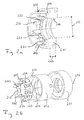
- FIG. 2a shows schematically a longitudinal section of an assembly with a sleeve, which has spring contact elements and a seal.
- FIG. 2b schematically shows an exploded view of the in FIG. 2 shown in longitudinal section arrangement.
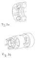
- FIGS. 3a and b show an alternative to the one in FIG. 2 illustrated embodiment.
- FIG. 1 schematically shows a longitudinal section of an arrangement 101 for an electrode lead terminal of an implantable device.
- the arrangement 101 comprises a sleeve 105 with a centrally extending sleeve longitudinal axis 114, the sleeve 105 enclosing a sleeve interior 104.
- the sleeve 105 can be arranged in an electrode line bushing such that the sleeve longitudinal axis 114 forms a common axis with a bushing longitudinal axis or is parallel to this.
- the sleeve interior 104 is in each case open at the ends of the sleeve 105, so that a connector of an electrode line 112, shown in sections in this figure, can be introduced continuously into the sleeve interior 104 along the sleeve longitudinal axis 114.
- the sleeve 105 includes a sleeve wall 106, wherein on the inside of the sleeve walls 106 spring-contact elements 107 and 108 are arranged pointing in the radial direction inwardly.
- the spring contact elements 108 and 107 are arranged in the sleeve interior, in the radial direction of the sleeve longitudinal axis 114 and thus also counteract the introduced illustrated in this figure plug an electrode line 112.
- the spring-contact element 107 is formed from a metallic spring tongue and turned parallel opposite to a spring transverse axis 118 alternately, so that the spring-contact element 107 has two turning sections, each with opposite Wenderaumssinn.
- the spring contact element 107 is designed to form, under deflection, at least along a spring deflection axis 122, a force counteracting the deflection.
- the deflection is effected in this embodiment by the inserted along the sleeve longitudinal axis 114 plug an electrode line 112 along the Federausschungsachse 122 radially outward, ie in the direction sleeve wall 106, so that the spring-contact element 107 is compressed.
- the sleeve 105 also includes a spring contact element 108 disposed on the inside of the sleeve wall 106.
- the spring-contact element 108 is just like the spring-contact element 107 formed from a metallic spring tongue and also has two turning sections, each with opposite Wenderaumssinn.
- the spring contact element 108 is designed to form, under deflection along a spring deflection axis 120, a deflection force counteracting the deflection force.
- the spring deflection axis 120 and the spring transverse axis 116 are mutually orthogonal; the spring deflection axis 122 and the spring transverse axis 116 are also mutually orthogonal.
- FIG. 2a 3 shows, schematically illustrated, a longitudinal section of a representation of an arrangement 201 for an electrode line connection bush, which comprises a sleeve 202 with a sleeve wall 203, spring contact elements 230, 231, 232, 233, and a sealing ring 211 with a sealing ring thickness 212.
- the sealing ring 211 has a circular opening 213 for receiving an electrode conduit with a round cross-section and is shaped such that the sleeve wall is sealed against the opening 213.
- the sleeve 202 has an arranged in the sleeve interior partition 204, which divides the sleeve interior along a - not shown in this figure - sleeve longitudinal axis.
- the partition wall 204 has a centrally arranged circular opening for passing through an electrode line plug.
- the diameter of the partition breakthrough corresponds to the diameter of the gasket breakthrough 213.
- the sealing washer 211 has a sealing washer thickness 212 so that the aperture of the sealing washer 211 has a breakthrough inner wall.
- the breakthrough inner wall has two longitudinally arranged in sleeve longitudinal axis sealing lips. The sealing lips each have radially inwardly and are integrally formed on the sealing disc.
- FIG. 2b shows - shown schematically - an exploded view of in FIG. 2a in longitudinal section shown arrangement for an electrode line socket.
- the arrangement for an electrode lead bush comprises a sleeve 202, a sealing washer 211 and a spring-contact element carrier 215 with six molded spring contact elements 230, 231, 232, 233, 234 and 235.
- the sleeve 202 has a sleeve wall 203, which comprises a sleeve interior.
- the sleeve interior is open along the sleeve longitudinal axis 214 to the sleeve ends at least at one end and in the embodiment at both ends (end faces).
- the sleeve 202 has a partition wall 204, which is arranged in the sleeve interior and formed on the sleeve wall 203.
- the partition 204 has a centrally arranged circular opening for the passage of an electrode line plug along the sleeve longitudinal axis 204.
- the partition wall 204 is spaced from the sleeve ends in the direction of the sleeve longitudinal axis 204 in each case.
- the spring-contact element carrier 215 is designed as a circular flat disc, which has a centrally arranged opening for the passage of an electrode line plug.
- the spring contact element carrier 215 has six circumferentially uniformly arranged spring contact elements 230, 231, 232, 233, 234 and 235, which are integrally formed on the outer edge of the spring contact element carrier 215.
- the spring contact elements are each formed from a wavy turned leaf spring, wherein the leaf spring has two turning sections each having opposite Wenderaumssinn and thus has an S-shaped waveform.
- the thus formed spring-contact elements 230, 231, 232, 233, 234 and 235 are formed under deflection along the Federausschungsachse a deflection of the counteracting spring force and can - in the application - When introducing an electrode line connector resiliently - substantially radially - dodge to the outside.
- the spring contact element carrier 215 has in the circumferential direction in each case laterally adjacent to the spring contact elements recess areas.
- the spring-contact element carrier also has in the circumferential direction on the inner edge, which adjoins the opening of the spring-contact element carrier, each with respect to each spring contact element arranged recess regions.
- the spring contact element carrier 215 and the spring contact elements are punched from a piece of sheet metal.
- the spring-contact elements are each formed of radially radially outwardly facing leaf spring strips which are bent at right angles to form the waveform on the circumferential extension of the spring-contact element carrier 215 and formed in the further course to an S-shaped waveform.
- the recesses on the side of the spring contact elements are cut so deep in the radial direction that the right angle bent spring contact element does not exceed the outer diameter of the spring-contact element carrier.
- the recesses on the inner edge of the spring-contact element carrier 215 for breakthrough are cut outwardly so deeply in the radial direction that a still standing area of the spring-contact element carrier 215 between the outer and inner recesses - as seen in the radial direction - forms a torsional spring acting in the tangential direction.
- the torsion spring thus formed supports the spring action of the spring contact element such that the torsion spring acts in series with the spring contact element.
- the resulting total spring stiffness, formed from the spring stiffness of the torsion spring and the spring stiffness of the spring contact element, is smaller than the spring stiffness of the spring contact element without the series-acting torsion spring.
- the spring-contact element carrier 215 is dimensioned in its outer peripheral diameter such that it can be inserted along the sleeve longitudinal axis in the sleeve interior.
- the arrangement also includes a - in FIG. 2a already described sealing washer 211, which has a ring groove spaced from the outer sealing disc edge.
- the diameter of the ring groove corresponds to the diameter of the sleeve 202, so that one end of the sleeve wall 203 can be inserted in the direction of the sleeve longitudinal axis in the annular groove of the sealing washer 212.
- FIGS. 3a and 3b differs from the previously described by the design of the spring contact elements. These each have only one turning section and are C-shaped.
Landscapes
- Health & Medical Sciences (AREA)
- Engineering & Computer Science (AREA)
- Biomedical Technology (AREA)
- Nuclear Medicine, Radiotherapy & Molecular Imaging (AREA)
- Radiology & Medical Imaging (AREA)
- Life Sciences & Earth Sciences (AREA)
- Animal Behavior & Ethology (AREA)
- General Health & Medical Sciences (AREA)
- Public Health (AREA)
- Veterinary Medicine (AREA)
- Electrotherapy Devices (AREA)
- Details Of Connecting Devices For Male And Female Coupling (AREA)
- Coupling Device And Connection With Printed Circuit (AREA)
- Measuring Leads Or Probes (AREA)
Description
- Die Erfindung betrifft eine Kontakt-Anordnung zum Anschluss einer Elektrodenleitung an ein implantierbares Gerät. Die Kontakt-Anordnung weist eine elektrische Anschlussbuchse mit einer Buchsenlängsachse und wenigstens einer Öffnung zum Einführen eines Steckers entlang der Buchsenlängsachse auf. Die Kontakt-Anordnung weist auch mindestens ein elektrisch leitfähiges Federkontaktelement auf, welches ausgebildet und angeordnet ist, beim Einführen eines Steckers federnd elastisch nach außen auszuweichen, dabei wenigstens in einer quer zur Buchsenlängsachse verlaufenden Federauslenkungsrichtung komprimiert zu werden und eine dem Komprimieren entgegenwirkende Federkraft auszubilden.
- Feder-Kontaktelemente für implantierbare Geräte sind aus dem Stand der Technik bekannt. Aus der
DE 196 09 367 der Anmelderin ist ein Herzschrittmacher mit einer rund ausgebildeten Hülse zur Aufnahme einer Elektrodenleitung bekannt, welche radial nach innen federnde Feder-Kontaktelemente aufweist, welche gleichmäßig am Hülsenumfang verteilt sind. Die Feder-Kontaktelemente sind streifenförmig ausgebildet, einseitig an der Hülsenwand befestigt und weisen in den Hülsenraum, wobei ihr freies Ende halbkugelförmig konvex ausgebildet ist und mit der konvexen Seite radial nach innen weist. - Solche Feder-Kontaktelemente haben das Problem, dass sich die Kontaktfeder-Andruckkraft nur schwierig einstellen lässt, insbesondere, wenn - wie oft üblich - das Federelement aus der Hülsenwand ausgestanzt und die somit erhaltene Blattfeder in den Innenraum gebogen ist. Hinsichtlich der Materialauswahl zur Herstellung der Feder ist man hier auf das Hülsenmaterial angewiesen, so dass in einem solchen Fall stets ein Kompromiss zwischen Anforderungen an eine Hülse und den Anforderungen an eine Kontaktfeder zur Herstellung eines sicheren und guten elektrischen Wirkkontaktes mit einer Elektrodenleitung gebildet wird.
- Die der Erfindung zugrunde liegende Aufgabe ist es daher, ein Kontaktelement anzugeben, welches einen sicheren galvanischen Kontakt mit einem Elektrodenleitungs-Stecker ermöglicht.
- Dokument
EP-A-0 840 400 offenbart eine Vorrichtung gemäß Oberbegriff des Anspruchs 1. - Die Aufgabe wird durch eine Kontakt-Anordnung mit einer Anschlussbuchse für ein implantierbares Gerätes der eingangs genannten Art gelöst, wobei das FederKontaktelement das Feder-Kontaktelement eine einstückige, metallische Federkontaktzunge mit quer zur Federauslenkungsrichtung verlaufenden Federkontaktzungen-Abschnitten aufweist, die durch Wendeabschnitte miteinander verbunden sind, wobei in Federrichtung unmittelbar aufeinanderfolgende Wendeabschnitte jeweils einen entgegengesetztem Wenderichtungssinn aufweisen, wobei das Feder-Kontaktelement drei oder vier Wendeabschnitte aufweist.
- In einer bevorzugten Ausführungsform weist das Feder-Kontaktelement eine Federkontaktzunge auf. Die Federkontaktzunge ist derart gewendet ist, dass die Federkontaktzunge in einer Aufsicht auf eine von der Buchsenlängsachse und der Federauslenkungsrichtung aufgespannten Ebene eine Wellenform hat.
- Bei einem wellenförmigen Feder-Kontaktelement mit zwei oder mehreren Wendeabschnitten lässt sich besonders vorteilhaft ein Feder-Kontaktelement mit einer weichen Federsteife in Federauslenkungsrichtung ausbilden. Ein weiterer Vorteil eines solchen Feder-Kontaktelements ist, dass die Federsteife in Federrichtung leicht einstellbar ist.
- Die Wellenform des Feder-Kontaktelements kann eine S-förmige, eine rechteckförmige oder eine dreieckförmige Wellenform sein. Durch die Ausbildung des Federkontaktelements gemäß verschiedener Wellenformen weist das Feder-Kontaktelement je nach gewählter Wellenform eine unterschiedliche Federsteife, insbesondere in Abhängigkeit von einer durch das Komprimieren bewirkten Federauslenkung auf. Dadurch lässt sich vorteilhaft eine gewünschte Federsteife über die Wahl der Wellenform einstellen.
- Durch die erzielte Serienschaltung von - jeweils durch Wendeabschnitte gebildete - Feder-Kontaktelemente kann ein Feder-Kontaktelement eine besonders weiche Federsteife aufweisen.
- In einer bevorzugten Ausführungsform ist die Federkontaktzunge des Feder-Kontaktelements eine gewendete Blattfeder. Die Blattfeder hat ein Blattfeder-Querschnittsprofil, dessen Breitenabmessung größer ist als dessen Höhenabmessung. Durch die Ausbildung als gewendete Blattfeder weist das Feder-Kontaktelement eine hohe Torsionsstabilität tangential zur Federauslenkungsrichtung auf. Im Anwendungsfall lässt sich ein Feder-Kontaktelement nicht so leicht verbiegen, wenn ein Elektrodenleitungs-Stecker nicht genau parallel zur Buchsenlängsachse in die Elektrodenleitungs-Anschlussbuchse eingeführt wird.
- Bevorzugt beträgt die Breitenabmessung des Blattfederquerschnitts das fünffache der Höhenabmessung des Blattfederquerschnitts.
- In einer alternativen Ausführungsform kann die Federkontaktzunge einen quadratischen oder runden Querschnitt aufweisen.
- In einer bevorzugten Ausführungsform weist die Anordnung mindestens drei Feder-Kontaktelemente auf, wobei die Federauslenkungsrichtungen der Feder-Kontaktelemente in einer gemeinsamen, senkrecht zur Buchsenlängsachse verlaufenden Ebene angeordnet sind.
- Dadurch kann ein Ringkontakt eines Elektrodenleitungs-Steckers im Anwendungsfall von mehreren Feder-Kontaktelementen berührt werden, so dass dadurch eine hohe Kontaktsicherheit, verbunden mit einem niedrigen elektrischen Kontakt-Übergangswiderstand erzielt wird.
- In einer bevorzugten Ausführungsform weist ein Kontaktabschnitt der Federkontaktzunge einen zur Berührung mit einem Gegenkontakt eines Elektrodenleitungs-Steckers vorgesehenen Oberflächenbereich auf, welcher konvex geformt ist. Im Anwendungsfall wird dadurch vorteilhaft das Einführen eines Elektrodenleitungs-Steckers in die Elektrodenleitungs-Anschlussbuchse erleichtert.
- Vorteilhafte Ausführungsformen einer Federkontaktzunge weisen eines oder eine Kombination der folgenden Materialien auf:
- Hochlegierte Stähle nach DIN 17224: X 12 CrNi 17 7; X 7 CrNiAl 17 7; oder X 5 CrNiMo 18 10 oder andere hochlegierte Metallegierungen.
- Eine Federkontaktzunge kann wenigstens abschnittweise vorteilhaft versilbert, vergoldet, mit Platinbromid (PtBr) beschichtet oder eine Kombination aus diesen Beschichtungen aufweisen. Beispielsweise ist eine Federkontaktzunge verkupfert und obenauf versilbert.
- In einer anderen Ausführungsform weist das Feder-Kontaktelement wenigstens ein Elastomer-Element auf, welches einen Zwischenraum mindestens teilweise auffüllt, welches sich zwischen zwei in Federauslenkungsrichtung gegenüberliegenden Blattfeder-Abschnitten erstreckt, wobei das Elastomer-Material als Auslenkungsweg-Begrenzer ausgebildet und angeordnet ist.
- Dadurch wird vorteilhaft eine plastische Verformung des Feder-Kontaktelements, verursacht durch eine zu große Auslenkung, verhindert. Beispielsweise ist das Elastomer-Element ein Silikon-Elastomer-Element, welches einen Silikonkautschuk enthält.
- In einer bevorzugten Ausführungsform ist das Elastomer-Element derart ausgeformt, dass es den Zwischenraum teilweise, bevorzugt bis zur Hälfte in Auslenkungsrichtung auffüllt.
- In einer anderen Ausführungsform ist das Elastomer-Element ausgeformt, den Zwischenraum vollständig aufzufüllen, wobei das Elastomer-Element-Material einen Elastizitätsmodul aufweist, welcher derart gewählt ist, dass das Elastomer-Element die Gesamtfedersteife des Feder-Kontaktelements entlang der Feder-auslenkungsrichtung nicht wesentlich erhöht.
- Bevorzugt ist das Elastizitätsmodul des Elastomer-Elements derart gewählt, dass die Gesamtfedersteife des Feder-Kontaktelements um nicht mehr als 5 % erhöht ist im Vergleich zu einer Federsteife eines Feder-Kontaktelements ohne ein Elastomer-Element.
- In einer vorteilhaften Ausführungsform ist das Elastomer-Element derart ausgeformt, dass es das Feder-Kontaktelement bis auf einen zum elektrischen Kontaktieren vorgesehenen Abschnitt vollständig umgibt. Bei dieser Ausführungsform ist das Feder-Kontaktelement vorteilhaft gegen Feuchtigkeit, Korrosion und plastische Verformung geschützt.
- In einer bevorzugten Ausführungsform weist eine Feder-Kontaktelement-Anordnung für eine Kontakt-Anordnung einen Feder-Kontaktelement-Träger mit mindestens drei, bevorzugt vier, weiter bevorzugt sechs angeformten Feder-Kontaktelementen auf. Der Feder-Kontaktelement-Träger ist als kreisrunde flache Scheibe ausgebildet, welche einen - bevorzugt zentrisch angeordneten - Durchbruch zur Durchführung eines Steckers aufweist.
- In einer weiter bevorzugten Ausführungsform sind die Feder-Kontaktelemente am Feder-Kontaktelement-Träger in Umfangsrichtung gleichmäßig angeordnet und im Bereich des äußeren Randes des Feder-Kontaktelement-Trägers angeformt.
- Besonders bevorzugt sind die Feder-Kontaktelemente jeweils aus einer wellenförmig gewendeten Blattfederzunge gebildet, wobei die Blattfederzunge zwei Wendeabschnitte mit jeweils einander entgegengesetztem Wenderichtungssinn aufweist und so eine S-förmige Wellenform hat. Die Blattfederzungen sind ausgebildet, unter Auslenkung entlang einer Federauslenkungsachse eine der Auslenkung entgegenwirkende Federkraft auszubilden und beim Einführen eines Steckers federnd elastisch nach außen auszuweichen.
- In einer vorteilhaften Ausführungsvariante weist der Feder-Kontaktelement-Träger in Umfangsrichtung jeweils seitlich an die Federkontaktelemente anschließende Aussparungs-Bereiche aufweist.
- Weiter bevorzugt weist der Feder-Kontaktelement-Träger in Umfangsrichtung an der Innenkante, welche an den Durchbruch des Feder-Kontaktelement-Trägers angrenzt, jeweils gegenüber eines jeden Federkontaktelements angeordnete Aussparungsbereiche auf. Die Aussparungen am inneren Rand des Feder-Kontaktelement-Trägers zum Durchbruch hin sind bevorzugt derart tief in radiale Richtung nach außen eingeschnitten, dass ein noch stehender Bereich des Feder-Kontaktelement-Trägers zwischen den äußeren und den inneren Aussparungen - gesehen in radialer Richtung - eine in tangentialer Richtung wirkende Torsionsfeder bildet. Die Torsionsfeder wirkt in Serie zu den Federkontaktelementen und erleichtert vorteilhaft das Einführen eines Steckers in eine Anschlussbuchse.
- In einer bevorzugten Ausführungsvariante ist der Feder-Kontaktelement-Träger mit den Federkontaktelementen aus einem einstückigen Blech gebildet, welches strahlenförmig radial nach außen weisende Blattfederstreifen aufweist. Die Feder-Kontaktelemente sind jeweils aus den strahlenförmig radial nach außen weisenden Blattfederstreifen gebildet, wobei die Blattfederstreifen am Umfangsansatz des Feder-Kontaktelement-Trägers - bevorzugt rechtwinklig - abgewinkelt und im weiteren Verlauf zu einer S-förmigen Wellenform ausgeformt sind.
- Der Feder-Kontaktelement-Träger mit den Federkontaktelementen kann aus einem Blech gestanzt oder lasergeschnitten sein.
- In einer vorteilhaften Ausführungsform sind die Aussparungen seitlich der Feder-kontaktelemente derart tief in radiale Richtung eingeschnitten, dass die Aussparungen seitlich der Federkontaktelemente derart tief in radiale Richtung eingeschnitten sind, dass nach mindestens rechtwinkligem Abwinkeln eines Blattfederstreifens ein Abschnitt des Blattfederstreifens beginnend am Umfang des Feder-Kontaktelement-Trägers (215) einen äußeren Umfangsradius des Feder-Kontaktelement-Trägers (215) neben den Aussparungen nicht überschreitet.
- In einer bevorzugten Ausführungsform umfasst die Anordnung auch eine Hülse mit einer Hülsenlängsachse und einer Hülsenwand. Die Hülsenwand umschließt einen Hülseninnenraum, welcher wenigstens eine Öffnung zum Einführen eines Elektroden-Steckers in Richtung der Hülsenlängsachse aufweist.
- In der hier beschriebenen Ausführungsform sind die Hülsenlängsachse und die Buchsenlängsachse der Anschlussbuchse zueinander parallel oder bilden eine gemeinsame Achse. Das Feder-Kontaktelement kann wenigstens teilweise in dem Hülseninnenraum angeordnet sein.
- In einer Ausführungsform weist die Hülsenwand einen Durchbruch zur Aufnahme eines Feder-Kontaktelements auf, wobei das Feder-Kontaktelement derart in dem Durchbruch angeordnet ist, dass mindestens ein zum elektrischen Kontaktieren eines Elektrodenleitungs-Steckers vorgesehener Abschnitt des Feder-Kontaktelements in dem Hülseninnenraum angeordnet ist.
- In einer besonders bevorzugten Ausführungsform ist die Hülsenwand zylindrisch ausgebildet und der Hülseninnenraum weist in Richtung der Hülsenlängsachse zwei Öffnungen zur Aufnahme eines Elektroden-Steckers auf, so dass die Hülse in Richtung der Hülsenlängsachse vollständig durchbrochen ist. Die Hülsenwand kann auch einen halbkreisförmigen, rechteckigen oder quadratischen Querschnitt haben.
- Weiter bevorzugt weist die Hülse mindestens drei, besonders bevorzugt sechs Feder-Kontaktelemente auf, wobei die Feder-Kontaktelemente in einer gemeinsamen, senkrecht zur Buchsenlängsachse verlaufenden Ebene angeordnet sind.
- Die Erfindung betrifft auch ein implantierbares Gerät mit einer zuvor beschriebenen Kontakt-Anordnung. Das implantierbare Gerät kann ein Herzschrittmacher, ein Kardioverter, ein Defibrillator oder eine Kombination aus diesen sein. Die Elektrodenleitungs-Anschlussbuchse ist bevorzugt im Header eines implantierbaren Gerätes angeordnet.
- Die in den Figuren gezeigten Ansführungs beispiele sind nicht Teil der Erfindung.
-
Figur 1 zeigt schematisch einen Längsschnitt eines Ausführungsbeispiels einer Anordnung für eine Elektrodenleitungs-Anschlussbuchse mit einer Hülse und Feder-Kontaktelementen. -
Figur 2a zeigt schematisch einen Längsschnitt einer Anordnung mit einer Hülse, welche Feder-Kontaktelemente und eine Dichtung aufweist. -
Figur 2b zeigt schematisch eine Explosionsdarstellung der inFigur 2 in Längsschnitt gezeigten Anordnung. -
Figuren 3a und b zeigen eine Alternative zur der inFigur 2 abgebildeten Ausführungsvariante. -
Figur 1 zeigt - schematisch dargestellt - einen Längsschnitt einer Anordnung 101 für eine Elektrodenteitungs-Anschlussbuchse eines implantierbaren Geräts. - Die Anordnung 101 umfasst eine Hülse 105 mit einer zentrisch verlaufenden Hülsenlängsachse 114, wobei die Hülse 105 einen Hülseninnenraum 104 umschließt.
- Die Hülse 105 kann in einer Elektrodenleitungsbuchse derart angeordnet sein, dass die Hülsenlängsachse 114 mit einer Buchsenlängsachse eine gemeinsame Achse bildet oder zu dieser parallel ist.
- Der Hülseninnenraum 104 ist an den Enden der Hülse 105 jeweils geöffnet, so dass ein - in dieser Figur abschnittsweise dargestellter - Stecker einer Elektrodenleitung 112 entlang der Hülsenlängsachse 114 durchgängig in den Hülseninnenraum 104 eingeführt werden kann.
- Die Hülse 105 umfasst eine Hülsenwand 106, wobei an der Innenseite der Hülsenwänd 106 Feder-Kontaktelemente 107 und 108 in radialer Richtung nach innen weisend angeordnet sind. Die Feder-Kontaktelemente 108 und 107 sind in dem Hülseninnenraum angeordnet, in radialer Richtung der Hülsenlängsachse 114 und somit auch dem in dieser Abbildung dargestellten eingeführten Stecker einer Elektrodenleitung 112 entgegenzufedern.
- Das Feder-Kontaktelement 107 ist aus einer metallischen Federzunge gebildet und parallel zu einer Federquerachse 118 alternierend entgegengesetzt gewendet, so dass das Feder-Kontaktelement 107 zwei Wendeabschnitte mit jeweils entgegengesetztem Wenderichtungssinn aufweist. Das Feder-Kontaktelement 107 ist ausgebildet, unter Auslenkung wenigstens entlang einer FederAuslenkungsachse 122 eine der Auslenkung entgegenwirkende Kraft auszubilden. Die Auslenkung wird in diesem Ausführungsbeispiel durch den entlang der Hülsenlängsachse 114 eingeführten Stecker einer Elektrodenleitung 112 entlang der Federauslenkungsachse 122 radial nach außen, also in Richtung Hülsenwand 106 bewirkt, so dass das Feder-Kontaktelement 107 komprimiert wird.
- Die Hülse 105 umfasst auch ein an der Innenseite der Hülsenwand 106 angeordnetes Feder-Kontaktelement 108.
- Das Feder-Kontaktelement 108 ist genauso wie das Feder-Kontaktelement 107 aus einer metallischen Federzunge gebildet und weist auch zwei Wendeabschnitte mit jeweils entgegengesetztem Wenderichtungssinn auf.
- Das Feder-Kontaktelement 108 ist ausgebildet, unter Auslenkung entlang einer Federauslenkungsachse 120 eine der Auslenkung entgegenwirkende Federkraft auszubilden. Die Federauslenkungsachse 120 und die Federquerachse 116 sind zueinander orthogonal; die Federauslenkungsachse 122 und die Federquerachse 116 sind auch zueinander orthogonal.
-
Figur 2a zeigt - schematisch dargestellt - einen Längsschnitt einer Darstellung einer Anordnung 201 für eine Elektrodenleitungs-Anschlussbuchse, welche eine Hülse 202 mit einer Hülsenwand 203, Feder-Kontaktelemente 230, 231, 232, 233, und einen Dichtungsring 211 mit einer Dichtungsringdicke 212 umfasst. Der Dichtungsring 211 weist einen kreisrunden Durchbruch 213 zur Aufnahme einer Elektrodenleitung mit rundem Querschnitt auf und ist derart geformt, dass die Hülsenwand gegen den Durchbruch 213 abgedichtet ist. - Die Hülse 202 weist eine in dem Hülseninnenraum angeordnete Trennwand 204 auf, welche den Hülseninnenraum entlang einer - in dieser Abbildung nicht dargestellten - Hülsenlängsachse teilt. Die Trennwand 204 weist einen zentrisch angeordneten kreisrunden Durchbruch zum Durchführen eines Elektrodenleitungs-Steckers auf. Der Durchmesser des Trennwand- Durchbruchs entspricht dem Durchmesser des Dichtungsscheibendurchbruchs 213.
- Die Dichtungsscheibe 211 weist eine Dichtungsscheibendicke 212 auf, so dass der Durchbruch der Dichtungsscheibe 211 eine Durchbruch-Innenwand aufweist. Die Durchbruch-Innenwand weist zwei in Hülsenlängsachse hintereinander angeordnete Dichtlippen auf. Die Dichtlippen weisen jeweils radial nach innen und sind an die Dichtscheibe angeformt.
-
Figur 2b zeigt - schematisch dargestellt - eine Explosionsdarstellung der inFigur 2a in Längsschnitt dargestellten Anordnung für eine Elektrodenleitungsbuchse. - Die Anordnung für eine Elektrodenleitungsbuchse umfasst eine Hülse 202, eine Dichtungsscheibe 211 und einen Feder-Kontaktelement-Träger 215 mit sechs angeformten Feder-Kontaktelementen 230, 231, 232, 233, 234 und 235.
- Die Hülse 202 weist eine Hülsenwand 203 auf, welche einen Hülseninnenraum umfasst. Der Hülseninnenraum ist entlang der Hülsenlängsachse 214 zu den Hülsenenden wenigstens an einem Ende und im Ausführungsbeispiel an beiden Enden (Stirnseiten) geöffnet.
- Die Hülse 202 weist eine Trennwand 204 auf, welche in dem Hülseninnenraum angeordnet und an die Hülsenwand 203 angeformt ist. Die Trennwand 204 weist einen zentrisch angeordneten kreisrunden Durchbruch zur Durchführung eines Elektrodenleitungssteckers entlang der Hülsenlängsachse 204 auf. Die Trennwand 204 ist von den Hülsenenden in Richtung der Hülsenlängsachse 204 jeweils beabstandet.
- Der Feder-Kontaktelement-Träger 215 ist als kreisrunde flache Scheibe ausgebildet, welche einen zentrisch angeordneten Durchbruch zur Durchführung eines Elektrodenleitungssteckers aufweist.
- Der Feder-Kontaktelement-Träger 215 weist sechs in Umfangsrichtung gleichmäßig angeordnete Feder-Kontaktelemente 230, 231, 232, 233, 234 und 235 auf, welche am äußeren Rand des Feder-Kontaktelement-Trägers 215 angeformt sind.
- Die Feder-Kontaktelemente sind jeweils aus einer wellenförmig gewendeten Blattfeder gebildet, wobei die Blattfeder zwei Wendeabschnitte mit jeweils entgegengesetztem Wenderichtungssinn aufweist und so eine S-förmige Wellenform aufweist.
- Die so ausgebildeten Feder-Kontaktelemente 230, 231, 232, 233, 234 und 235 sind ausgebildet, unter Auslenkung entlang der Federauslenkungsachse eine der Auslenkung entgegenwirkende Federkraft auszubilden und können - im Anwendungsfall - bei Einführung eines Elektrodenleitungssteckers federnd elastisch - im wesentlichen radial - nach außen ausweichen.
- Der Feder-Kontaktelement-Träger 215 weist in Umfangsrichtung jeweils seitlich an die Federkontaktelemente anschließende Aussparungs-Bereiche auf.
- Der Feder-Kontaktelement-Träger weist auch in Umfangsrichtung an der Innenkante, welche an den Durchbruch des Feder-Kontaktelement-Trägers angrenzt, jeweils gegenüber eines jeden Federkontaktelements angeordnete Aussparungsbereiche auf.
- In diesem Ausführungsbeispiel ist der Feder-Kontaktelement-Träger 215 und die Federkontaktelemente aus einem Blechstück gestanzt. Die Feder-Kontaktelemente sind jeweils aus strahlenförmig radial nach außen weisenden Blattfederstreifen gebildet, welche zur Ausbildung der Wellenform am Umfangsansatz des Feder-Kontaktelement-Trägers 215 rechtwinklig abgebogen und im weiteren Verlauf zu einer S-förmigen Wellenform ausgeformt sind.
- Die Aussparungen seitlich der Federkontaktelemente sind derart tief in radiale Richtung eingeschnitten, dass das rechtwinklig abgebogene Federkontaktelement den äußeren Durchmesser des Feder-Kontaktelement-Trägers nicht überschreitet.
- Die Aussparungen am inneren Rand des Feder-Kontaktelement-Trägers 215 zum Durchbruch hin sind derart tief in radiale Richtung nach außen eingeschnitten, dass ein noch stehender Bereich des Feder-Kontaktelement-Trägers 215 zwischen den äußeren und den inneren Aussparungen - gesehen in radialer Richtung - eine in tangentialer Richtung wirkende Torsionsfeder bildet.
- Die so gebildete Torsionsfeder unterstützt die Federwirkung des Feder-Kontaktelements derart, dass die Torsionsfeder in Serie zu dem Feder-Kontaktelement wirkt. Die daraus resultierende Gesamtfedersteife, gebildet aus der Federsteife der Torsionsfeder und der Federsteife des Federkontaktelements, ist kleiner als die Federsteife des Feder-Kontaktelements ohne die in Serie wirkende Torsionsfeder.
- Der Feder-Kontaktelement-Träger 215 ist in seinem äußeren Umfangsdurchmesser derart bemessen, dass er entlang der Hülsenlängsachse in den Hülseninnenraum eingeführt werden kann.
- Die Anordnung umfasst auch eine - in
Figur 2a bereits beschriebene - Dichtungsscheibe 211, welche eine vom äußeren Dichtungsscheibenrand beabstandete Ring-Nut aufweist. Der Durchmesser der Ring-Nut entspricht dem Durchmesser der Hülse 202, sodass ein Ende der Hülsenwand 203 in Richtung der Hülsenlängsachse in die Ring-Nut der Dichtungsscheibe 212 eingeschoben werden kann. - Die Ausführungsvariante gemäß
Figuren 3a und 3b unterscheidet sich von der zuvor Beschriebenen durch die Gestaltung der Federkontaktelemente. Diese weisen jeweils nur einen Wendeabschnitt auf und sind C-förmig ausgebildet. Die vorteilhafte Kombination von einer Dichtscheibe mit einem Federkontaktelement-Träger mit nach innen ragenden Federkontaktelementen, die innerhalb einer gemeinsamen Hülse in Hülsenlängsrichtung hintereinander angeordnet sind, ist bei beiden Ausführungsvarianten gleichermaßen verwirklicht.
Claims (17)
- Kontakt-Anordnung (101, 201) zum Anschluss einer Elektrodenleitung an ein implantierbares Gerät, mit
einer elektrischen Anschlussbuchse mit einer Buchsenlängsachse (114, 214) und wenigstens einer Öffnung zum Einführen eines Steckers entlang der Buchsenlängsachse (214),
mit mindestens einem elektrisch leitfähigen Federkontaktelement (107, 108, 230, 231, 232, 233, 234, 235), welches ausgebildet und angeordnet ist, beim Einführen eines Steckers federnd elastisch nach außen auszuweichen, dabei wenigstens in einer quer zur Buchsenlängsachse verlaufenden Federauslenkungsrichtung komprimiert zu werden und eine dem Komprimieren entgegenwirkende Federkraft auszubilden, wobei
das Feder-Kontaktelement (107, 108, 230, 231, 232, 233, 234, 235) eine einstückige, metallische Federkontaktzunge mit quer zur Federauslenkungsrichtung (120, 122) verlaufenden Federkontaktzungen-Abschnitten aufweist, die durch Wendeabschnitte miteinander verbunden sind, wobei in Federauslenkungsrichtung (120, 122) unmittelbar aufeinanderfolgende Wendeabschnitte jeweils einem entgegengesetzten Wenderichtungssinn aufweisen,
dadurch gekennzeichnet, dass das Feder-Kontaktelement drei oder vier Wendeabschnitte aufweist. - Kontakt-Anordnung (101, 201) nach Anspruch 1, dadurch gekennzeichnet, dass die Federkontaktzunge derart gewendet ist, dass die Federkontaktzunge in einer Aufsicht auf eine von der Buchsenlängsachse (114, 214) und der Federauslenkungsrichtung (120, 122) aufgespannten Ebene eine Wellenform hat.
- Kontakt-Anordnung (101, 201) nach Anspruch 2, dadurch gekennzeichnet, dass die Wellenform eine S-förmige oder eine rechteckförmige oder eine dreieckförmige Wellenform ist.
- Kontakt-Anordnung (101, 201) nach einem der vorhergehenden Ansprüche, dadurch gekennzeichnet, dass die Federkontaktzunge des Feder-Kontaktelements (107, 108, 230, 231, 232, 233, 234, 235) eine gewendete Blattfeder mit einem Blattfeder-Querschnittsprofil ist, wobei die Breitenabmessung des Blattfeder-Querschnittsprofils größer ist als die Höhenabmessung des Blattfeder-Querschnittsprofils.
- Kontakt-Anordnung (101, 201) nach einem der vorhergehenden Ansprüche, welche mindestens drei Feder-Kontaktelemente (107, 108, 230, 231, 232, 233, 234, 235) aufweist, wobei die Federauslenkungsrichtungen der Feder-Kontaktelemente (107, 108, 230, 231, 232, 233, 234, 235) auf einer gemeinsamen, senkrecht zur Buchsenlängsachse (114, 214) verlaufenden Ebene angeordnet sind.
- Kontakt-Anordnung (101, 201) nach einem der vorhergehenden Ansprüche, dadurch gekennzeichnet, dass ein Kontaktabschnitt der Federkontaktzunge einen zur Berührung mit einem Gegenkontakt eines Elektrodenleitungs-Steckers vorgesehenen Oberflächenbereich aufweist, welcher konvex geformt ist.
- Kontakt-Anordnung (101, 201) nach einem der vorhergehenden Ansprüche, dadurch gekennzeichnet, dass das Feder-Kontaktelement (107, 108, 230, 231, 232, 233, 234, 235) wenigstens ein Elastomer-Element aufweist, welches einen Zwischenraum mindestens teilweise auffüllt, welcher sich zwischen zwei in radialer Richtung gegenüberliegenden Blattfederabschnitten erstreckt, wobei das Elastomer-Element als Auslenkungsweg-Begrenzer ausgebildet und angeordnet ist.
- Kontakt-Anordnung (101, 201) nach einem der vorhergehenden Ansprüche, dadurch gekennzeichnet, dass die Anordnung eine Hülse (105) mit einer Hülsenlängsachse (114, 214) und einer Hülsenwand (106) aufweist, wobei
die Hülsenwand (106) einen Hülseninnenraum (104) umschließt, welcher wenigstens eine Öffnung zur Aufnahme eines Elektrodensteckers in Richtung der Hülsenlängsachse (114, 214) aufweist,
und wobei die Hülsenlängsachse (114, 214) und die Buchsenlängsachse (114, 214) zueinander parallel sind, und das Feder-Kontaktelement (107, 108, 230, 231, 232, 233, 234, 235) wenigstens teilweise in dem Hülseninnenraum (104) angeordnet ist. - Feder-Kontaktelement-Anordnung für eine Kontakt-Anordnung nach einem der vorhergehenden Ansprüche, mit einem Feder-Kontaktelement-Träger (215), welcher mindestens drei angeformte Feder-Kontaktelemente (230, 231, 232, 233, 234, 235) aufweist, wobei der Feder-Kontaktelement-Träger (215) als kreisförmige flache Scheibe ausgebildet ist, welche einen Durchbruch zur Durchführung eines Steckers aufweist.
- Feder-Kontaktelement-Anordnung nach Anspruch 9; dadurch gekennzeichnet, dass die Feder-Kontaktelemente (230, 231, 232, 233, 234, 235) am Feder-Kontaktelement-Träger (215) in Umfangsrichtung gleichmäßig angeordnet und im Bereich des äußeren Randes des Feder-Kontaktelement-Trägers (215) angeformt sind.
- Feder-Kontaktelement-Anordnung nach Anspruch 9 oder 10, dadurch gekennzeichnet, dass die Feder-Kontaktelemente (230, 231, 232, 233, 234, 235) jeweils von einer wellenförmig gewendeten Blattfederzunge gebildet sind, wobei die Blattfederzunge zwei Wendeabschnitte mit jeweils einander entgegengesetztem Wenderichtungssinn aufweist und so eine S-förmige Wellenform hat und die Blattfederzungen ausgebildet sind, unter Auslenkung entlang der Federauslenkungsachse eine der Auslenkung entgegenwirkende Federkraft auszubilden und beim Einführen eines Steckers federnd elastisch nach außen auszuweichen.
- Feder-Kontaktelement-Anordnung nach einem der Ansprüche 9 bis 11; dadurch gekennzeichnet, dass der Feder-Kontaktelement-Träger (215) in Umfangsrichtung jeweils seitlich an die Federkontaktelemente anschließende Aussparungs-Bereiche aufweist.
- Feder-Kontaktelement-Anordnung nach einem der Ansprüche 9 bis 12, dadurch gekennzeichnet, dass der Feder-Kontaktelement-Träger (215) in Umfangsrichtung an der Innenkante, welche an den Durchbruch des Feder-Kontaktelement-Trägers angrenzt, jeweils gegenüber eines jeden Federkontaktelements angeordnete Aussparungsbereiche aufweist.
- Feder-Kontaktelement-Anordnung nach einem der Ansprüche 9 bis 13, dadurch gekennzeichnet, dass der Feder-Kontaktelement-Träger (215) mit den Federkontaktelementen aus einem einstückigen Blech gebildet ist, welches strahlenförmig radial nach außen weisende Blattfederstreifen aufweist und die Feder-Kontaktelemente jeweils aus den strahlenförmig radial nach außen weisenden Blattfederstreifen gebildet sind, wobei die Blattfederstreifen-Ansätze am Umfang des Feder-Kontaktelement-Trägers (215) abgewinkelt und im weiteren Verlauf zu einer S-förmigen Wellenform ausgeformt sind.
- Feder-Kontaktelement-Anordnung nach Anspruch 14, dadurch gekennzeichnet, dass die Blattfederstreifen am Umfangsansatz des Feder-Kontaktelement-Trägers (215) rechtwinklig abgewinkelt sind.
- Feder-Kontaktelement-Anordnung nach einem der Ansprüche 14 oder 15, dadurch gekennzeichnet, dass die Aussparungen seitlich der Federkontaktelemente derart tief in radiale Richtung eingeschnitten sind, dass nach mindestens rechtwinkligem Abwinkeln eines Blattfederstreifens ein Abschnitt des Blattfederstreifens beginnend am Umfang des Feder-Kontaktelement-Trägers (215) einen äußeren Umfangsradius des Feder-Kontaktelement-Trägers (215) neben den Aussparungen nicht überschreitet.
- Implantierbares Gerät mit einer Kontakt-Anordnung (101, 201) oder einer Feder-Kontaktelement-Anordnung nach einem der vorhergehenden Ansprüche, dadurch gekennzeichnet, dass das implantierbare Gerät ein Herzschrittmacher, ein Kardioverter, ein Defibrillator oder eine Kombination aus diesen ist.
Priority Applications (1)
| Application Number | Priority Date | Filing Date | Title |
|---|---|---|---|
| EP08008087A EP1952840A1 (de) | 2004-04-05 | 2005-04-01 | Kontaktanordnung |
Applications Claiming Priority (2)
| Application Number | Priority Date | Filing Date | Title |
|---|---|---|---|
| DE102004017659 | 2004-04-05 | ||
| DE102004017659A DE102004017659A1 (de) | 2004-04-05 | 2004-04-05 | Federkontaktelement |
Related Child Applications (2)
| Application Number | Title | Priority Date | Filing Date |
|---|---|---|---|
| EP08008087A Division EP1952840A1 (de) | 2004-04-05 | 2005-04-01 | Kontaktanordnung |
| EP08008087.2 Division-Into | 2008-04-28 |
Publications (3)
| Publication Number | Publication Date |
|---|---|
| EP1584350A2 EP1584350A2 (de) | 2005-10-12 |
| EP1584350A3 EP1584350A3 (de) | 2005-12-28 |
| EP1584350B1 true EP1584350B1 (de) | 2012-01-04 |
Family
ID=34895557
Family Applications (2)
| Application Number | Title | Priority Date | Filing Date |
|---|---|---|---|
| EP05102602A Expired - Lifetime EP1584350B1 (de) | 2004-04-05 | 2005-04-01 | Federkontaktelement |
| EP08008087A Ceased EP1952840A1 (de) | 2004-04-05 | 2005-04-01 | Kontaktanordnung |
Family Applications After (1)
| Application Number | Title | Priority Date | Filing Date |
|---|---|---|---|
| EP08008087A Ceased EP1952840A1 (de) | 2004-04-05 | 2005-04-01 | Kontaktanordnung |
Country Status (4)
| Country | Link |
|---|---|
| US (1) | US7587244B2 (de) |
| EP (2) | EP1584350B1 (de) |
| AT (1) | ATE539798T1 (de) |
| DE (1) | DE102004017659A1 (de) |
Families Citing this family (44)
| Publication number | Priority date | Publication date | Assignee | Title |
|---|---|---|---|---|
| DE102005042369A1 (de) * | 2005-09-07 | 2007-03-15 | Biotronik Crm Patent Ag | Einschraubelektrodensonde zur kardiologischen Anwendung |
| DE102006053729A1 (de) | 2006-11-15 | 2008-05-21 | Biotronik Crm Patent Ag | Kontaktanordnung, Kontaktbaugruppe, implantierbare Vorrichtung und Elektrodenleitung |
| DE102007039554B4 (de) * | 2007-08-22 | 2010-07-29 | Osypka, Peter, Dr.- Ing. | Herzschrittmacher-Elektrode mit Schraubwendel und Zuleitungswendel |
| US9095728B2 (en) | 2008-09-05 | 2015-08-04 | Medtronic, Inc. | Electrical contact for implantable medical device |
| US8075337B2 (en) * | 2008-09-30 | 2011-12-13 | Belden Inc. | Cable connector |
| DE102009001573B3 (de) * | 2009-03-16 | 2010-08-05 | Tyco Electronics Amp Gmbh | Elektrisch leitendes Federelement, Kontaktelement und Steckverbinder |
| CN102667267B (zh) * | 2009-12-29 | 2015-11-25 | 美国圣戈班性能塑料公司 | 弹簧及其形成方法 |
| US8731670B2 (en) * | 2010-04-27 | 2014-05-20 | Oscor Inc. | Passive electrical connector |
| US8666494B2 (en) * | 2010-04-29 | 2014-03-04 | Donatelle Plastics, Inc. | Header for implantable pulse generator and method of making same |
| NL2005480C2 (nl) | 2010-10-07 | 2012-04-11 | Meco Equip Eng | Inrichting voor het eenzijdig elektrolytisch behandelen van een vlak substraat. |
| US20120089203A1 (en) * | 2010-10-12 | 2012-04-12 | Advanced Neuromodulation Systems, Inc. | Electrical connections for use in implantable medical devices |
| DK2636105T3 (en) | 2010-11-01 | 2017-08-21 | Ppc Broadband Inc | ELECTRICAL CONNECTOR WITH EARTH ELEMENT |
| US8376769B2 (en) | 2010-11-18 | 2013-02-19 | Holland Electronics, Llc | Coaxial connector with enhanced shielding |
| US9252499B2 (en) | 2010-12-23 | 2016-02-02 | Mediatek Inc. | Antenna unit |
| DE102011101856A1 (de) * | 2011-01-21 | 2012-07-26 | Abb Technology Ag | Kontaktsystem für Stromleiter |
| US8157588B1 (en) | 2011-02-08 | 2012-04-17 | Belden Inc. | Cable connector with biasing element |
| US8428724B2 (en) * | 2011-03-11 | 2013-04-23 | Greatbatch Ltd. | Low insertion force electrical connector for implantable medical devices |
| US9931513B2 (en) | 2011-03-29 | 2018-04-03 | Nuvectra Corporation | Feed-through connector assembly for implantable pulse generator and method of use |
| US8369951B2 (en) | 2011-03-29 | 2013-02-05 | Greatbatch Ltd. | Feed-through connector assembly for implantable pulse generator and method of use |
| US8738141B2 (en) | 2011-04-07 | 2014-05-27 | Greatbatch, Ltd. | Contact assembly for implantable pulse generator and method of use |
| US8579652B2 (en) * | 2011-06-16 | 2013-11-12 | Leoni Studer Ag | Fastening device for an electric cable |
| US8915753B2 (en) * | 2011-12-12 | 2014-12-23 | Holland Electronics, Llc | Signal continuity connector |
| JP5873933B2 (ja) | 2011-12-28 | 2016-03-01 | カーディアック ペースメイカーズ, インコーポレイテッド | スイッチバックパターンを含む環状圧縮性要素 |
| US9138586B2 (en) | 2012-01-27 | 2015-09-22 | Greatbatch Ltd. | Contact block using spherical electrical contacts for electrically contacting implantable leads |
| US9662506B2 (en) * | 2013-07-18 | 2017-05-30 | Boston Scientific Neuromodulation Corporation | Systems and methods for making and using improved operating-room cables for electrical stimulation systems |
| US9362666B2 (en) * | 2014-09-12 | 2016-06-07 | Cooper Technologies Company | Anti-decoupling spring |
| US9278224B1 (en) | 2014-11-03 | 2016-03-08 | Donatelle Plastics, Inc. | Electrical connector ring for implantable medical device |
| EP3187224B1 (de) | 2016-01-04 | 2021-06-02 | Donatelle Plastics, Inc. | Elektrischer verbinderring für implantierbare medizinische vorrichtung |
| USD833978S1 (en) | 2016-04-22 | 2018-11-20 | Westinghouse Air Brake Technologies Corporation | Rail car power connector |
| US10199766B2 (en) * | 2016-04-22 | 2019-02-05 | Westinghouse Air Brake Technologies Corporation | Breakaway railcar power connector |
| US9666973B1 (en) * | 2016-06-10 | 2017-05-30 | Amphenol Corporation | Self-locking connector coupling |
| DE102017110696B4 (de) | 2017-05-17 | 2025-01-30 | Hanon Systems | Motorgehäuse eines Verdichters und Verfahren zur Kontaktierung eines elektrischen Motors |
| US11139603B2 (en) | 2017-10-03 | 2021-10-05 | Boston Scientific Neuromodulation Corporation | Connectors with spring contacts for electrical stimulation systems and methods of making and using same |
| DE102017218133B4 (de) * | 2017-10-11 | 2025-06-05 | Bayerische Motoren Werke Aktiengesellschaft | Schirmübergabe für eine Steckverbindung |
| DE102017124775A1 (de) * | 2017-10-24 | 2019-04-25 | Karl Storz Se & Co. Kg | Handhabungseinrichtung für ein mikroinvasives medizinisches Instrument |
| WO2019210112A1 (en) * | 2018-04-25 | 2019-10-31 | Ppc Broadband, Inc. | Coaxial cable connectors having port grounding |
| CN110732083A (zh) * | 2018-07-20 | 2020-01-31 | 苏州景昱医疗器械有限公司 | 连接医疗器械的医用连接器和脉冲发生器 |
| DE102019206388A1 (de) * | 2019-05-03 | 2020-11-05 | Neuroloop GmbH | Implantierbare elektrische Kontaktanordnung |
| CA3150507A1 (en) * | 2019-09-17 | 2021-03-25 | Jacob J. Carr | NEURO-STIMULATOR ARRANGEMENTS |
| DE102020200976A1 (de) | 2020-01-28 | 2021-07-29 | Te Connectivity Germany Gmbh | Abschirmfederhülse für Hochstromsteckverbindungen |
| DE102020210534B4 (de) * | 2020-04-30 | 2023-03-23 | Te Connectivity Germany Gmbh | Kontaktsystem |
| DE102021102864B3 (de) * | 2021-02-08 | 2022-01-20 | Heraeus Deutschland GmbH & Co. KG | Federkontaktring |
| US12485271B2 (en) | 2021-04-15 | 2025-12-02 | Tc1 Llc | Systems and methods for medical device connectors |
| TWI819791B (zh) * | 2022-09-13 | 2023-10-21 | 晝思有限公司 | 探針頭、探針組件及所組成的彈簧式探針結構 |
Family Cites Families (14)
| Publication number | Priority date | Publication date | Assignee | Title |
|---|---|---|---|---|
| US3678445A (en) * | 1970-07-31 | 1972-07-18 | Itt | Electrical connector shield |
| CA1070792A (en) * | 1976-07-26 | 1980-01-29 | Earl A. Cooper | Electrical connector and frequency shielding means therefor and method of making same |
| US4426127A (en) * | 1981-11-23 | 1984-01-17 | Omni Spectra, Inc. | Coaxial connector assembly |
| US4423919A (en) * | 1982-04-05 | 1984-01-03 | The Bendix Corporation | Electrical connector |
| US5275620A (en) | 1990-05-21 | 1994-01-04 | Telectronics, N.V. | Implantable lead connectors and remote lead assembly |
| US5252090A (en) | 1992-09-30 | 1993-10-12 | Telectronics Pacing Systems, Inc. | Self-locking implantable stimulating lead connector |
| DE19609367A1 (de) * | 1996-03-04 | 1997-09-11 | Biotronik Mess & Therapieg | Herzschrittmacher |
| US5730628A (en) * | 1996-09-25 | 1998-03-24 | Pacesetter, Inc. | Multi-contact connector for an implantable medical device |
| EP0840400A3 (de) * | 1996-11-05 | 1999-06-30 | Vlt Corporation | Buchsenkontakt |
| JP3338980B2 (ja) * | 1996-12-13 | 2002-10-28 | モレックス インコーポレーテッド | 三次元立体回路体及びその中継用端子 |
| US6332815B1 (en) * | 1999-12-10 | 2001-12-25 | Litton Systems, Inc. | Clip ring for an electrical connector |
| US7003351B2 (en) * | 2003-02-25 | 2006-02-21 | Cardiac Pacemakers, Inc. | Ring connector for implantable medical devices |
| US7164951B2 (en) * | 2003-07-31 | 2007-01-16 | Medtronic, Inc. | Electrical connector assembly having integrated conductive element and elastomeric seal for coupling medical leads to implantable medical devices |
| US20050107859A1 (en) * | 2003-11-14 | 2005-05-19 | Terry Daglow | System and method of establishing an electrical connection between an implanted lead and an electrical contact |
-
2004
- 2004-04-05 DE DE102004017659A patent/DE102004017659A1/de not_active Withdrawn
-
2005
- 2005-04-01 AT AT05102602T patent/ATE539798T1/de active
- 2005-04-01 EP EP05102602A patent/EP1584350B1/de not_active Expired - Lifetime
- 2005-04-01 EP EP08008087A patent/EP1952840A1/de not_active Ceased
- 2005-04-05 US US11/099,064 patent/US7587244B2/en not_active Expired - Fee Related
Also Published As
| Publication number | Publication date |
|---|---|
| ATE539798T1 (de) | 2012-01-15 |
| US7587244B2 (en) | 2009-09-08 |
| DE102004017659A1 (de) | 2005-10-27 |
| US20060004419A1 (en) | 2006-01-05 |
| EP1952840A1 (de) | 2008-08-06 |
| EP1584350A3 (de) | 2005-12-28 |
| EP1584350A2 (de) | 2005-10-12 |
Similar Documents
| Publication | Publication Date | Title |
|---|---|---|
| EP1952840A1 (de) | Kontaktanordnung | |
| DE112009002729B4 (de) | Verbinder mit niedriger Anschluss-Einführkraft und Verfahren zur Reduzierung der selbigen | |
| EP1275173B1 (de) | Stecker mit einer hülse | |
| EP1459411B1 (de) | Kabelanschluss | |
| EP0308784B1 (de) | Klemmbrille für die Halterung von Pendelgleitlagern | |
| EP1022836A2 (de) | Kabelverschraubung | |
| EP2403070A1 (de) | Federkontakt | |
| EP0793974A2 (de) | Implantierbares Elektrostimulationsgerät und Elektrodenleitung | |
| DE102009030463A1 (de) | Elektrischer Steckverbinder | |
| DE19804625C2 (de) | Gummipfropfen für wasserdichte Verbinder | |
| DE1615718B1 (de) | Kontaktbuchse fuer elektrische Buchsen-Stift-Steckverbindungen | |
| DE102012002145A1 (de) | Hülsenkontakt für einen elektrischen Nullkraftsteckverbinder | |
| EP0935310B1 (de) | Kontaktelement mit einem Schraubanschluss | |
| WO1979000635A1 (fr) | Connecteur electrique et procede de fabrication | |
| DE3912189A1 (de) | Schutzleiterverbindung | |
| EP1913661B1 (de) | Stecker mit haltefeder für einen erdungskontakt | |
| WO2020030371A1 (de) | Anordnung zur elektrischen kontaktierung und stromverbinder | |
| WO2019175283A1 (de) | Verbindungsanordnung für schutzleiterkontakt | |
| WO2002089155A1 (de) | Magnetspulenanordnung | |
| DE10117570B4 (de) | Elektrischer Kontakt sowie Lampenfassung und Anschluss- oder Verbindungsklemme mit mindestens einem solchen Kontakt | |
| DE4037712C2 (de) | Fahrzeugantenne | |
| DE3408432A1 (de) | Fuer eine elektrische steckkontaktvorrichtung vorgesehenes kontaktstueck | |
| EP0405337A2 (de) | Schutzstecker für eine Verteilerleiste in einer Telekommunikationsanlage | |
| DE10339958B4 (de) | Elektrischer Steckkontakt | |
| DE8705154U1 (de) | Zweiteiliges Gehäuse für ein Haushaltsgerät |
Legal Events
| Date | Code | Title | Description |
|---|---|---|---|
| PUAI | Public reference made under article 153(3) epc to a published international application that has entered the european phase |
Free format text: ORIGINAL CODE: 0009012 |
|
| AK | Designated contracting states |
Kind code of ref document: A2 Designated state(s): AT BE BG CH CY CZ DE DK EE ES FI FR GB GR HU IE IS IT LI LT LU MC NL PL PT RO SE SI SK TR |
|
| AX | Request for extension of the european patent |
Extension state: AL BA HR LV MK YU |
|
| PUAL | Search report despatched |
Free format text: ORIGINAL CODE: 0009013 |
|
| AK | Designated contracting states |
Kind code of ref document: A3 Designated state(s): AT BE BG CH CY CZ DE DK EE ES FI FR GB GR HU IE IS IT LI LT LU MC NL PL PT RO SE SI SK TR |
|
| AX | Request for extension of the european patent |
Extension state: AL BA HR LV MK YU |
|
| RAP1 | Party data changed (applicant data changed or rights of an application transferred) |
Owner name: BIOTRONIK CRM PATENT AG |
|
| 17P | Request for examination filed |
Effective date: 20060125 |
|
| AKX | Designation fees paid |
Designated state(s): AT BE BG CH CY CZ DE DK EE ES FI FR GB GR HU IE IS IT LI LT LU MC NL PL PT RO SE SI SK TR |
|
| 17Q | First examination report despatched |
Effective date: 20071123 |
|
| GRAP | Despatch of communication of intention to grant a patent |
Free format text: ORIGINAL CODE: EPIDOSNIGR1 |
|
| GRAS | Grant fee paid |
Free format text: ORIGINAL CODE: EPIDOSNIGR3 |
|
| GRAA | (expected) grant |
Free format text: ORIGINAL CODE: 0009210 |
|
| AK | Designated contracting states |
Kind code of ref document: B1 Designated state(s): AT BE BG CH CY CZ DE DK EE ES FI FR GB GR HU IE IS IT LI LT LU MC NL PL PT RO SE SI SK TR |
|
| REG | Reference to a national code |
Ref country code: GB Ref legal event code: FG4D Free format text: NOT ENGLISH |
|
| REG | Reference to a national code |
Ref country code: DE Ref legal event code: R081 Ref document number: 502005012288 Country of ref document: DE Owner name: BIOTRONIK SE & CO. KG, DE Free format text: FORMER OWNER: BIOTRONIK GMBH & CO. KG, 12359 BERLIN, DE |
|
| REG | Reference to a national code |
Ref country code: CH Ref legal event code: EP |
|
| REG | Reference to a national code |
Ref country code: AT Ref legal event code: REF Ref document number: 539798 Country of ref document: AT Kind code of ref document: T Effective date: 20120115 |
|
| REG | Reference to a national code |
Ref country code: IE Ref legal event code: FG4D |
|
| REG | Reference to a national code |
Ref country code: DE Ref legal event code: R096 Ref document number: 502005012288 Country of ref document: DE Effective date: 20120301 |
|
| REG | Reference to a national code |
Ref country code: SE Ref legal event code: TRGR |
|
| REG | Reference to a national code |
Ref country code: NL Ref legal event code: VDEP Effective date: 20120104 |
|
| PG25 | Lapsed in a contracting state [announced via postgrant information from national office to epo] |
Ref country code: SI Free format text: LAPSE BECAUSE OF FAILURE TO SUBMIT A TRANSLATION OF THE DESCRIPTION OR TO PAY THE FEE WITHIN THE PRESCRIBED TIME-LIMIT Effective date: 20120104 |
|
| LTIE | Lt: invalidation of european patent or patent extension |
Effective date: 20120104 |
|
| PG25 | Lapsed in a contracting state [announced via postgrant information from national office to epo] |
Ref country code: IS Free format text: LAPSE BECAUSE OF FAILURE TO SUBMIT A TRANSLATION OF THE DESCRIPTION OR TO PAY THE FEE WITHIN THE PRESCRIBED TIME-LIMIT Effective date: 20120504 Ref country code: LT Free format text: LAPSE BECAUSE OF FAILURE TO SUBMIT A TRANSLATION OF THE DESCRIPTION OR TO PAY THE FEE WITHIN THE PRESCRIBED TIME-LIMIT Effective date: 20120104 Ref country code: NL Free format text: LAPSE BECAUSE OF FAILURE TO SUBMIT A TRANSLATION OF THE DESCRIPTION OR TO PAY THE FEE WITHIN THE PRESCRIBED TIME-LIMIT Effective date: 20120104 Ref country code: BG Free format text: LAPSE BECAUSE OF FAILURE TO SUBMIT A TRANSLATION OF THE DESCRIPTION OR TO PAY THE FEE WITHIN THE PRESCRIBED TIME-LIMIT Effective date: 20120404 |
|
| PG25 | Lapsed in a contracting state [announced via postgrant information from national office to epo] |
Ref country code: GR Free format text: LAPSE BECAUSE OF FAILURE TO SUBMIT A TRANSLATION OF THE DESCRIPTION OR TO PAY THE FEE WITHIN THE PRESCRIBED TIME-LIMIT Effective date: 20120405 Ref country code: PL Free format text: LAPSE BECAUSE OF FAILURE TO SUBMIT A TRANSLATION OF THE DESCRIPTION OR TO PAY THE FEE WITHIN THE PRESCRIBED TIME-LIMIT Effective date: 20120104 Ref country code: PT Free format text: LAPSE BECAUSE OF FAILURE TO SUBMIT A TRANSLATION OF THE DESCRIPTION OR TO PAY THE FEE WITHIN THE PRESCRIBED TIME-LIMIT Effective date: 20120504 Ref country code: FI Free format text: LAPSE BECAUSE OF FAILURE TO SUBMIT A TRANSLATION OF THE DESCRIPTION OR TO PAY THE FEE WITHIN THE PRESCRIBED TIME-LIMIT Effective date: 20120104 |
|
| PGFP | Annual fee paid to national office [announced via postgrant information from national office to epo] |
Ref country code: GB Payment date: 20120423 Year of fee payment: 8 Ref country code: SE Payment date: 20120423 Year of fee payment: 8 |
|
| PG25 | Lapsed in a contracting state [announced via postgrant information from national office to epo] |
Ref country code: CY Free format text: LAPSE BECAUSE OF FAILURE TO SUBMIT A TRANSLATION OF THE DESCRIPTION OR TO PAY THE FEE WITHIN THE PRESCRIBED TIME-LIMIT Effective date: 20120104 |
|
| BERE | Be: lapsed |
Owner name: BIOTRONIK CRM PATENT A.G. Effective date: 20120430 |
|
| PG25 | Lapsed in a contracting state [announced via postgrant information from national office to epo] |
Ref country code: DK Free format text: LAPSE BECAUSE OF FAILURE TO SUBMIT A TRANSLATION OF THE DESCRIPTION OR TO PAY THE FEE WITHIN THE PRESCRIBED TIME-LIMIT Effective date: 20120104 Ref country code: CZ Free format text: LAPSE BECAUSE OF FAILURE TO SUBMIT A TRANSLATION OF THE DESCRIPTION OR TO PAY THE FEE WITHIN THE PRESCRIBED TIME-LIMIT Effective date: 20120104 Ref country code: RO Free format text: LAPSE BECAUSE OF FAILURE TO SUBMIT A TRANSLATION OF THE DESCRIPTION OR TO PAY THE FEE WITHIN THE PRESCRIBED TIME-LIMIT Effective date: 20120104 Ref country code: EE Free format text: LAPSE BECAUSE OF FAILURE TO SUBMIT A TRANSLATION OF THE DESCRIPTION OR TO PAY THE FEE WITHIN THE PRESCRIBED TIME-LIMIT Effective date: 20120104 |
|
| PLBE | No opposition filed within time limit |
Free format text: ORIGINAL CODE: 0009261 |
|
| STAA | Information on the status of an ep patent application or granted ep patent |
Free format text: STATUS: NO OPPOSITION FILED WITHIN TIME LIMIT |
|
| PG25 | Lapsed in a contracting state [announced via postgrant information from national office to epo] |
Ref country code: MC Free format text: LAPSE BECAUSE OF NON-PAYMENT OF DUE FEES Effective date: 20120430 Ref country code: SK Free format text: LAPSE BECAUSE OF FAILURE TO SUBMIT A TRANSLATION OF THE DESCRIPTION OR TO PAY THE FEE WITHIN THE PRESCRIBED TIME-LIMIT Effective date: 20120104 Ref country code: IT Free format text: LAPSE BECAUSE OF FAILURE TO SUBMIT A TRANSLATION OF THE DESCRIPTION OR TO PAY THE FEE WITHIN THE PRESCRIBED TIME-LIMIT Effective date: 20120104 |
|
| 26N | No opposition filed |
Effective date: 20121005 |
|
| PG25 | Lapsed in a contracting state [announced via postgrant information from national office to epo] |
Ref country code: BE Free format text: LAPSE BECAUSE OF NON-PAYMENT OF DUE FEES Effective date: 20120430 |
|
| REG | Reference to a national code |
Ref country code: DE Ref legal event code: R097 Ref document number: 502005012288 Country of ref document: DE Effective date: 20121005 |
|
| PG25 | Lapsed in a contracting state [announced via postgrant information from national office to epo] |
Ref country code: ES Free format text: LAPSE BECAUSE OF FAILURE TO SUBMIT A TRANSLATION OF THE DESCRIPTION OR TO PAY THE FEE WITHIN THE PRESCRIBED TIME-LIMIT Effective date: 20120415 |
|
| REG | Reference to a national code |
Ref country code: AT Ref legal event code: MM01 Ref document number: 539798 Country of ref document: AT Kind code of ref document: T Effective date: 20120401 |
|
| PG25 | Lapsed in a contracting state [announced via postgrant information from national office to epo] |
Ref country code: AT Free format text: LAPSE BECAUSE OF NON-PAYMENT OF DUE FEES Effective date: 20120401 |
|
| REG | Reference to a national code |
Ref country code: SE Ref legal event code: EUG |
|
| GBPC | Gb: european patent ceased through non-payment of renewal fee |
Effective date: 20130401 |
|
| PG25 | Lapsed in a contracting state [announced via postgrant information from national office to epo] |
Ref country code: GB Free format text: LAPSE BECAUSE OF NON-PAYMENT OF DUE FEES Effective date: 20130401 Ref country code: SE Free format text: LAPSE BECAUSE OF NON-PAYMENT OF DUE FEES Effective date: 20130402 |
|
| PG25 | Lapsed in a contracting state [announced via postgrant information from national office to epo] |
Ref country code: TR Free format text: LAPSE BECAUSE OF FAILURE TO SUBMIT A TRANSLATION OF THE DESCRIPTION OR TO PAY THE FEE WITHIN THE PRESCRIBED TIME-LIMIT Effective date: 20120104 |
|
| PG25 | Lapsed in a contracting state [announced via postgrant information from national office to epo] |
Ref country code: LU Free format text: LAPSE BECAUSE OF NON-PAYMENT OF DUE FEES Effective date: 20120401 |
|
| PG25 | Lapsed in a contracting state [announced via postgrant information from national office to epo] |
Ref country code: HU Free format text: LAPSE BECAUSE OF FAILURE TO SUBMIT A TRANSLATION OF THE DESCRIPTION OR TO PAY THE FEE WITHIN THE PRESCRIBED TIME-LIMIT Effective date: 20050401 |
|
| PGFP | Annual fee paid to national office [announced via postgrant information from national office to epo] |
Ref country code: FR Payment date: 20140416 Year of fee payment: 10 |
|
| REG | Reference to a national code |
Ref country code: DE Ref legal event code: R082 Ref document number: 502005012288 Country of ref document: DE Representative=s name: RANDOLL, SOEREN, DIPL.-CHEM. UNIV. DR. RER. NA, DE |
|
| REG | Reference to a national code |
Ref country code: FR Ref legal event code: ST Effective date: 20151231 |
|
| PG25 | Lapsed in a contracting state [announced via postgrant information from national office to epo] |
Ref country code: FR Free format text: LAPSE BECAUSE OF NON-PAYMENT OF DUE FEES Effective date: 20150430 |
|
| PGFP | Annual fee paid to national office [announced via postgrant information from national office to epo] |
Ref country code: DE Payment date: 20170424 Year of fee payment: 13 Ref country code: IE Payment date: 20170424 Year of fee payment: 13 Ref country code: CH Payment date: 20170425 Year of fee payment: 13 |
|
| REG | Reference to a national code |
Ref country code: DE Ref legal event code: R082 Ref document number: 502005012288 Country of ref document: DE Ref country code: DE Ref legal event code: R081 Ref document number: 502005012288 Country of ref document: DE Owner name: BIOTRONIK SE & CO. KG, DE Free format text: FORMER OWNER: BIOTRONIK CRM PATENT AG, BAAR, CH |
|
| REG | Reference to a national code |
Ref country code: DE Ref legal event code: R119 Ref document number: 502005012288 Country of ref document: DE |
|
| REG | Reference to a national code |
Ref country code: CH Ref legal event code: PL |
|
| REG | Reference to a national code |
Ref country code: IE Ref legal event code: MM4A |
|
| PG25 | Lapsed in a contracting state [announced via postgrant information from national office to epo] |
Ref country code: DE Free format text: LAPSE BECAUSE OF NON-PAYMENT OF DUE FEES Effective date: 20181101 |
|
| PG25 | Lapsed in a contracting state [announced via postgrant information from national office to epo] |
Ref country code: LI Free format text: LAPSE BECAUSE OF NON-PAYMENT OF DUE FEES Effective date: 20180430 Ref country code: CH Free format text: LAPSE BECAUSE OF NON-PAYMENT OF DUE FEES Effective date: 20180430 |
|
| PG25 | Lapsed in a contracting state [announced via postgrant information from national office to epo] |
Ref country code: IE Free format text: LAPSE BECAUSE OF NON-PAYMENT OF DUE FEES Effective date: 20180401 |