EP1584150B1 - Method and apparatus for digital subscriber line access multiplexer stacking - Google Patents
Method and apparatus for digital subscriber line access multiplexer stacking Download PDFInfo
- Publication number
- EP1584150B1 EP1584150B1 EP04700392A EP04700392A EP1584150B1 EP 1584150 B1 EP1584150 B1 EP 1584150B1 EP 04700392 A EP04700392 A EP 04700392A EP 04700392 A EP04700392 A EP 04700392A EP 1584150 B1 EP1584150 B1 EP 1584150B1
- Authority
- EP
- European Patent Office
- Prior art keywords
- slave
- dslams
- dslam
- master
- architecture
- Prior art date
- Legal status (The legal status is an assumption and is not a legal conclusion. Google has not performed a legal analysis and makes no representation as to the accuracy of the status listed.)
- Expired - Lifetime
Links
- 238000000034 method Methods 0.000 title claims description 14
- 238000004891 communication Methods 0.000 claims abstract description 65
- 241001522296 Erithacus rubecula Species 0.000 claims abstract description 15
- 230000009977 dual effect Effects 0.000 claims description 10
- 230000008672 reprogramming Effects 0.000 claims description 5
- 230000011664 signaling Effects 0.000 claims description 5
- 230000007246 mechanism Effects 0.000 claims description 3
- 101150012579 ADSL gene Proteins 0.000 description 8
- 102100020775 Adenylosuccinate lyase Human genes 0.000 description 8
- 108700040193 Adenylosuccinate lyases Proteins 0.000 description 8
- 238000010586 diagram Methods 0.000 description 8
- 238000013459 approach Methods 0.000 description 4
- 238000013507 mapping Methods 0.000 description 2
- 238000012986 modification Methods 0.000 description 2
- 230000004048 modification Effects 0.000 description 2
- 238000012545 processing Methods 0.000 description 2
- 230000004044 response Effects 0.000 description 2
- 238000012546 transfer Methods 0.000 description 2
- 241000723353 Chrysanthemum Species 0.000 description 1
- 235000005633 Chrysanthemum balsamita Nutrition 0.000 description 1
- 230000008859 change Effects 0.000 description 1
- 238000006243 chemical reaction Methods 0.000 description 1
- 238000005516 engineering process Methods 0.000 description 1
- 230000007257 malfunction Effects 0.000 description 1
- 235000013550 pizza Nutrition 0.000 description 1
- 238000011084 recovery Methods 0.000 description 1
- 238000006467 substitution reaction Methods 0.000 description 1
Images




Classifications
-
- H—ELECTRICITY
- H04—ELECTRIC COMMUNICATION TECHNIQUE
- H04L—TRANSMISSION OF DIGITAL INFORMATION, e.g. TELEGRAPHIC COMMUNICATION
- H04L12/00—Data switching networks
- H04L12/54—Store-and-forward switching systems
- H04L12/56—Packet switching systems
- H04L12/5601—Transfer mode dependent, e.g. ATM
-
- H—ELECTRICITY
- H04—ELECTRIC COMMUNICATION TECHNIQUE
- H04L—TRANSMISSION OF DIGITAL INFORMATION, e.g. TELEGRAPHIC COMMUNICATION
- H04L12/00—Data switching networks
- H04L12/64—Hybrid switching systems
- H04L12/6418—Hybrid transport
-
- H—ELECTRICITY
- H04—ELECTRIC COMMUNICATION TECHNIQUE
- H04L—TRANSMISSION OF DIGITAL INFORMATION, e.g. TELEGRAPHIC COMMUNICATION
- H04L12/00—Data switching networks
- H04L12/54—Store-and-forward switching systems
- H04L12/56—Packet switching systems
- H04L12/5601—Transfer mode dependent, e.g. ATM
- H04L2012/5603—Access techniques
- H04L2012/5604—Medium of transmission, e.g. fibre, cable, radio
- H04L2012/5606—Metallic
-
- H—ELECTRICITY
- H04—ELECTRIC COMMUNICATION TECHNIQUE
- H04L—TRANSMISSION OF DIGITAL INFORMATION, e.g. TELEGRAPHIC COMMUNICATION
- H04L12/00—Data switching networks
- H04L12/54—Store-and-forward switching systems
- H04L12/56—Packet switching systems
- H04L12/5601—Transfer mode dependent, e.g. ATM
- H04L2012/5603—Access techniques
- H04L2012/5609—Topology
- H04L2012/561—Star, e.g. cross-connect, concentrator, subscriber group equipment, remote electronics
-
- H—ELECTRICITY
- H04—ELECTRIC COMMUNICATION TECHNIQUE
- H04L—TRANSMISSION OF DIGITAL INFORMATION, e.g. TELEGRAPHIC COMMUNICATION
- H04L12/00—Data switching networks
- H04L12/54—Store-and-forward switching systems
- H04L12/56—Packet switching systems
- H04L12/5601—Transfer mode dependent, e.g. ATM
- H04L2012/5625—Operations, administration and maintenance [OAM]
- H04L2012/5627—Fault tolerance and recovery
-
- H—ELECTRICITY
- H04—ELECTRIC COMMUNICATION TECHNIQUE
- H04L—TRANSMISSION OF DIGITAL INFORMATION, e.g. TELEGRAPHIC COMMUNICATION
- H04L12/00—Data switching networks
- H04L12/54—Store-and-forward switching systems
- H04L12/56—Packet switching systems
- H04L12/5601—Transfer mode dependent, e.g. ATM
- H04L2012/5638—Services, e.g. multimedia, GOS, QOS
- H04L2012/5665—Interaction of ATM with other protocols
-
- H—ELECTRICITY
- H04—ELECTRIC COMMUNICATION TECHNIQUE
- H04L—TRANSMISSION OF DIGITAL INFORMATION, e.g. TELEGRAPHIC COMMUNICATION
- H04L12/00—Data switching networks
- H04L12/64—Hybrid switching systems
- H04L12/6418—Hybrid transport
- H04L2012/6424—Access arrangements
- H04L2012/6427—Subscriber Access Module; Concentrator; Group equipment
-
- H—ELECTRICITY
- H04—ELECTRIC COMMUNICATION TECHNIQUE
- H04L—TRANSMISSION OF DIGITAL INFORMATION, e.g. TELEGRAPHIC COMMUNICATION
- H04L12/00—Data switching networks
- H04L12/64—Hybrid switching systems
- H04L12/6418—Hybrid transport
- H04L2012/6478—Digital subscriber line, e.g. DSL, ADSL, HDSL, XDSL, VDSL
-
- H—ELECTRICITY
- H04—ELECTRIC COMMUNICATION TECHNIQUE
- H04M—TELEPHONIC COMMUNICATION
- H04M11/00—Telephonic communication systems specially adapted for combination with other electrical systems
- H04M11/06—Simultaneous speech and data transmission, e.g. telegraphic transmission over the same conductors
- H04M11/062—Simultaneous speech and data transmission, e.g. telegraphic transmission over the same conductors using different frequency bands for speech and other data
-
- H—ELECTRICITY
- H04—ELECTRIC COMMUNICATION TECHNIQUE
- H04Q—SELECTING
- H04Q2213/00—Indexing scheme relating to selecting arrangements in general and for multiplex systems
- H04Q2213/13039—Asymmetrical two-way transmission, e.g. ADSL, HDSL
-
- H—ELECTRICITY
- H04—ELECTRIC COMMUNICATION TECHNIQUE
- H04Q—SELECTING
- H04Q2213/00—Indexing scheme relating to selecting arrangements in general and for multiplex systems
- H04Q2213/1305—Software aspects
-
- H—ELECTRICITY
- H04—ELECTRIC COMMUNICATION TECHNIQUE
- H04Q—SELECTING
- H04Q2213/00—Indexing scheme relating to selecting arrangements in general and for multiplex systems
- H04Q2213/13109—Initializing, personal profile
-
- H—ELECTRICITY
- H04—ELECTRIC COMMUNICATION TECHNIQUE
- H04Q—SELECTING
- H04Q2213/00—Indexing scheme relating to selecting arrangements in general and for multiplex systems
- H04Q2213/13145—Rerouting upon failure
-
- H—ELECTRICITY
- H04—ELECTRIC COMMUNICATION TECHNIQUE
- H04Q—SELECTING
- H04Q2213/00—Indexing scheme relating to selecting arrangements in general and for multiplex systems
- H04Q2213/13164—Traffic (registration, measurement,...)
-
- H—ELECTRICITY
- H04—ELECTRIC COMMUNICATION TECHNIQUE
- H04Q—SELECTING
- H04Q2213/00—Indexing scheme relating to selecting arrangements in general and for multiplex systems
- H04Q2213/13166—Fault prevention
-
- H—ELECTRICITY
- H04—ELECTRIC COMMUNICATION TECHNIQUE
- H04Q—SELECTING
- H04Q2213/00—Indexing scheme relating to selecting arrangements in general and for multiplex systems
- H04Q2213/13167—Redundant apparatus
-
- H—ELECTRICITY
- H04—ELECTRIC COMMUNICATION TECHNIQUE
- H04Q—SELECTING
- H04Q2213/00—Indexing scheme relating to selecting arrangements in general and for multiplex systems
- H04Q2213/13204—Protocols
-
- H—ELECTRICITY
- H04—ELECTRIC COMMUNICATION TECHNIQUE
- H04Q—SELECTING
- H04Q2213/00—Indexing scheme relating to selecting arrangements in general and for multiplex systems
- H04Q2213/1329—Asynchronous transfer mode, ATM
-
- H—ELECTRICITY
- H04—ELECTRIC COMMUNICATION TECHNIQUE
- H04Q—SELECTING
- H04Q2213/00—Indexing scheme relating to selecting arrangements in general and for multiplex systems
- H04Q2213/13298—Local loop systems, access network
Definitions
- This invention relates generally to the field of Digital Subscriber Line Access Multiplexers (DSLAMs) and, more particularly, to configuration and interconnection of DSLAMs to allow stacking efficiently with fault tolerance redundancy at low cost.
- DSLAMs Digital Subscriber Line Access Multiplexers
- Digital Subscriber Line Access Multiplexers are required for communications between digital subscriber line (DSL) users and the central office (CO).
- DSLAM digital subscriber line
- CO central office
- the "pizza box" sized DSLAMs are stacked at remote sites to provide higher density and ease of interconnection.
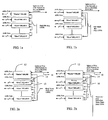
- Conventional stacking configurations of the DSLAMs are shown in FIGS. 1a and 1b of the drawings based on single link daisy chain and star respectively.
- EP 1,113,697 describes a network access apparatus which includes first and second master units, each having a physical interface to a packet-switched network.
- a plurality of slave units, each slave unit having one or more ports to respective subscriber lines, are linked by a plurality of physical interface lines in one or more daisy chains.
- An architecture for stacking DSLAMs employs a master DSLAM having a control circuit and an uplink communication circuit to a central office and two LVDS circuits for communication with two DSLAM boxes in adjacent circuit interconnection to the master DSLAM.
- Multiple slave DSLAMs each having a programmable control circuit and two LVDS circuits for communication with two DSLAM boxes immediately adjacent on either side in the circuit are connected in a ring or split stack arrangement.
- a control circuit in the master selectively programs the control circuits in each slave DSLAM to control the direction of communication in the LVDS circuits as round robin in a first selected mode and a split in a second selected mode to accommodate the desired structure and to provide redundancy for failure by reprogramming from round robin to split to communicate around a failed slave DSLAM.
- an architecture for stacking Digital Subscriber Line Access Multiplexers comprising: a master DSLAM having a control circuit and two low voltage differential signaling (LVDS) circuits for communication with two DSLAMs in direct adjacent circuit interconnection to the master DSLAM ; a plurality of slave DSLAMs each having a programmable control circuit and two LVDS circuits for communication with two DSLAMs in adjacent virtual circuit interconnection; and means for selectively programming the control circuit in each slave DSLAM to control a direction of communication in the LVDS circuits in each said slave DSLAM as round robin in a first selected mode and a split path in a second selected mode.
- LVDS low voltage differential signaling
- a method for operating an architecture that stacks Digital Subscriber Line Access Multiplexers comprising: using a control circuit of a master DSLAM to selectively program a control circuit in each of a plurality of slave DSLAMs to control a direction of communication in low voltage differential signaling (LVDS) circuits in said each slave DSLAM as round robin in a first selected mode; and if a failure in at least one of said slave DSLAMs is detected, using said control circuit of said master DSLAM to selectively program said control circuit in particular ones of the slave DSLAMs to control the direction of communication in the LVDS circuits as a split path in a second selected mode.
- DSLAM Digital Subscriber Line Access Multiplexers
- FIGs. 2a and b show the proposed new method of stacking based on "ring" or “dual link” architecture respectively.
- the stacking link 10 connecting the master box 12 and slave boxes 14 for the embodiments shown is based on low voltage differential signaling (LVDS) technology, designed to carry ATM traffic, as will be discussed in greater detail subsequently.
- LVDS low voltage differential signaling
- the uplink 16 for data traffic is shown as ATM based connecting to the central office (CO) or ATM network via OC-3 or (Multilink) E1/T1 IMA.
- the data flows in one direction from one box to another (i.e. to the one stacked below).
- the last box down the chain completes the "ring” by following the same data path to the master.
- the data flows bi-directionally (transmit/receive) from one box to another (i.e. to the one stacked below).
- the master splits the two traffic paths via software control, based either on virtual slave box identification numbers and/or ATM virtual path/virtual circuit numbers of a slave box.
- the Master to Slave and Slave to Slave interconnections alternate in each link, as shown.
- the chain connection order is from Master to Slave 1 to Slave 3, etc.
- the chain order is from Master to Slave 2 to Slave 4, etc.
- the last two slave boxes in each chain link then connect with each other on link 10' to complete the loop for the purpose of redundancy and traffic redirection in case a failure occurs as will be described in greater detail subsequently.
- a third alternative provides the two slave boxes connecting to the Master are the first Slave and a middle slave.
- the middle slave will #2.
- One link connects Master and Slave 1
- the other link connects Master and Slave 2 and then Slave 3.
- the middle slave will be 4 and one link will be Master and Slave 1 and then 2 and 3.
- the other link will be Master and Slave 4, and then 5 to 7.
- the flexibility of the invention allows this configuration to also be used for a Round Robin daisy chain link since the virtual "position" of the slave DSLAMs is programmable.
- the last link (10') will also be used for data traffic.
- the link path can be reconfigured by the Master to bi-directional as shown in FIG. 2d when a failure occurs.
- FIG. 3 shows an example of the reliability feature or self-healing available with the method of the present invention.
- the master can redirect traffic when informed the failure has occurred in one of the slave boxes by converting the traffic in the slave boxes to split path with bi-direction communication on both sides of the "down" slave box with communication to the master box at both ends of the chain.
- the link 10' is activated for normal communication.
- a first approach is for Master to periodically send a "heart-beat" message to each slave by means of polling in a round robin fashion. If the slave being polled (identified by virtual ID) does not respond within a pre-designated time, the Master will consider it has failed and redirect traffic around that slave.
- a second approach is that the slaves communicate with each other by sending heart-beat messages.
- the architecture can be programmed by the Master such that the box that is stacked "on top” always sends messages to the one that is stacked "below” or next in communication sequence.
- the Master sends heart-beat to Slave 1
- Slave 1 sends the heart-beat to Slave 2 and so on.
- the box receiving the heart-beat message does not respond within a pre-designated time
- the box sending the message will consider that box being failed and inform the Master using the reserved in-band communication channel (as described below).
- FIG. 4 shows an embodiment of the present invention with a dual master configuration with a second master box 18, providing full protection in the event one master fails. Coordination between the two masters is employed, in terms of traffic and configuration, such as active/standby, shared active/active, etc.
- FIG. 5 shows the internal main functional architecture of the master and slave DSLAMs and a general stacking arrangement.
- the master box incorporates multiple ADSL interfaces 20 for connection to the user lines 22.
- a control circuit 24 with a central processing unit (CPU) and ATM switching and traffic management controls the master DSLAM.
- An uplink circuit 26 provides communication with the CO using STM/OC3 or multilink EI/TI IMA. Communication with the slave boxes is provided by multiple LVDS circuits 28a and 28b.
- Each slave box also has multiple ADSL interfaces 30 for connection to the user lines 32.
- a control circuit 34 with a central processing unit (CPU) and ATM switching and traffic management controls the slave DSLAM under software control by the master.
- LVDS ports 36a and 36b interconnect the slave box for communication with each box adjacent in the circuit connection, either master or slave.
- the control circuit in the master DSLAM provides software instruction to the slave DSLAMs for establishing the communication direction as round robin or split, i.e. bi-directional, as will be described in greater detail subsequently. With the physical connection in a ring stack chain, the normal communication path would be round robin.
- failure of one slave box can be overcome by the master reprogramming the slaves to communicate in split format thereby automatically reconfiguring the circuit arrangement to a dual link configuration as previously described with respect to FIG. 3 .
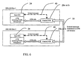
- the communications between the Master and Slaves and between the Slave DSLAMs for the embodiments shown are based on in-band communications carried within the LVDS link and ATM cell streams. This is also the CPU to CPU communication means between two DSLAM boxes via an in-band LVDS channel.
- FIG. 6 demonstrates this embodiment in schematic form.
- the CPU messages are inserted into the ATM cell streams by the LVDS circuit through the CPU interface as represented by links 40.
- the in-band communications are transmitted by the LVDS with the ATM cell streams on links 10 between DSLAMs.
- Each Slave DSLAM maintains a traffic relay and stacking I/O table that does the virtual channel and box ID mapping. The table is updated whenever instructed by the Master via in-band communication channel.
- FIG. 7 shows an example of the relay/stacking I/O table in a Slave DSLAM.
- the table incorporates the ADSL port numbers connected to the DSLAM, the VCI/VPIs for the Slave DSLAM, the virtual ID for the DSLAM and the Stacking Input/Output mode for each of the two LVDS ports.
- the stacking ports in the Utopia LVDS configuration shown for the embodiments in the drawings can be predefined as belonging to the "A" or "B" LVDS link during initialization. Each port can be programmed for input, output or bi-directional (input and output) communication.
- the Master DSLAM maintains a "proxy" table for all slaves, which includes VCI/VPI cross-connect information and mapping between external VCI/VPI to internal (slave) VCI/VPI, as well as stacking I/O configuration.
- the proxy table contains the information present in the tables for each of the Slaves and an additional data item defining the Master Stacking Mode for round robin or split path.
- the Stacking Input/Output mode established by the Master will be determined by the Stacking mode as previously described. Failure mode recovery can be accomplished by the Master as previously described resulting in a change in the Stacking mode and bypassing of a failed Slave DSLAM in the communications path.
- the communications relaying scheme for the Slaves is illustrated in FIGs. 9 and 10 for downlink and uplink paths respectively.
- the ATM data from the uplink is received by a DSLAM in block 50 and routed through an ATM switch 52.
- a determination is made in block 54 comparing the ATM cells with the DSLAM traffic relay and stacking table to determine if the communication is local or should be downlinked in the stack. If the communication is intended for an ADSL port in the DSLAM, it is switched to the appropriate local ADSL port in block 56. If the communication is to be passed through, a check of the stacking I/O table is made to determine the transfer port in block 58.
- the communication is passed to the new stacking port in block 60 for ATM output to the next DSLAM as defined by the new stacking port data. If the I/O table has not been updated, the communication is passed to the old stacking port in block 62 for ATM output to the next DSLAM as defined by the old stacking port data.
- Uplinking of data is shown in FIG. 10 where ATM data from the Downlink is received in block 64 from the local ADSL ports in the DSLAM or from the stacking input port.
- the data is routed through the ATM switch 66 and to the uplink switch 68 for external communication.
- a check of the stacking I/O table is made to determine the transfer port in block 70. If the I/O table has not been updated, the communication is passed to the old stacking port in block 72 for ATM output to the next DSLAM as defined by the old stacking port data. If the I/O table has been updated, the communication is passed to the new stacking port in block 74 for ATM output to the next DSLAM as defined by the new stacking port data.
- Uplink and downlink communications for the Master DSLAM are conducted based on the proxy table previously described with respect to FIG. 8 .
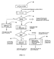
- ATM data is received by the Master from the uplink in block 80 through the ATM switch 82.
- a determination 84 is made whether the ATM cells correspond to a local ADSL port for the Master or require a stack downlink. If local the ATM cells are switched to the appropriate local DSL port in block 86, if not, a check 88 is made to determine the stacking mode. If a determination is made in block 90 that the round robin mode is present, the Master switches to the output stacking port previously defined in block 92.
- the proxy table allows conversion of the external VCI/VPI to internal (slave) VCI/VPI for downlink. If a split mode is used, a switch to the proper stacking port is made using the VCI/VPI cross connect table in block 94.
- the uplink proxy path is shown in FIG. 12 .
- ATM data from the local ADSL port in the Master or downlink slave DSLAM is received in block 96 through the ATM switch 98 and transmitted through the uplink in switch 100 with the Master conducting the VCI/VPI cross connect as required pursuant to the proxy table.
- Heartbeat communications and failure reprogramming are accomplished by the Master DSLAM using inband messaging as previously described.
- the failure sensing schemes reserve the in-band communication channel that is in the reverse direction of the normal ATM traffic, in order to inform the Master when failure occurs.
- the in-band communication channel is carried over the normal ATM traffic.
- the Master reprograms the Slave path direction in case of failure through the in-band communication channel by sending down stacking path I/O messages to each of the Slave boxes (minus the failed one).
- the Slave boxes then update their corresponding I/O tables.
- the Master incorporates a simple state machine that tracks the operating condition of each Slave box in its stacking control circuit.
- the failed DSLAM box when the failed DSLAM box is recovered to be operational again, it will inform the Master through the in-band communication channel to notify that it is alive. The Master then will either update the I/O table of all the Slaves including the recovered one, or by updating only the recovered Slave of its normal traffic I/O path that follows the rest of the traffic directions.
- the state machine for the described in-band communications is shown in FIG. 13 .
- the Master sends an initialization communication 102 to define the stacking I/O information table for each DSLAM.
- state 104 in response to heartbeat signals, communications proceed based on the initialized settings. If no heart-beat response is received or a failure notification is received, the Master enters state 106, identifies the failed Slave by its virtual ID and sends stacking I/O table updates to the remaining operational slaves. The remaining Slaves continue operation with the revised I/O stacking tables until the failed Slave communicates with the Master that it is recovered. Upon such notification, the Master enters state 108 and again sends updated stacking I/O table information to all Slaves in the stack before returning to the Operational state 104.
Landscapes
- Engineering & Computer Science (AREA)
- Computer Networks & Wireless Communication (AREA)
- Signal Processing (AREA)
- Data Exchanges In Wide-Area Networks (AREA)
- Time-Division Multiplex Systems (AREA)
Abstract
Description
- This invention relates generally to the field of Digital Subscriber Line Access Multiplexers (DSLAMs) and, more particularly, to configuration and interconnection of DSLAMs to allow stacking efficiently with fault tolerance redundancy at low cost.
- Digital Subscriber Line Access Multiplexers are required for communications between digital subscriber line (DSL) users and the central office (CO). Typically, the "pizza box" sized DSLAMs are stacked at remote sites to provide higher density and ease of interconnection. Conventional stacking configurations of the DSLAMs are shown in
FIGS. 1a and 1b of the drawings based on single link daisy chain and star respectively. -
EP 1,113,697 describes a network access apparatus which includes first and second master units, each having a physical interface to a packet-switched network. A plurality of slave units, each slave unit having one or more ports to respective subscriber lines, are linked by a plurality of physical interface lines in one or more daisy chains. - An architecture for stacking DSLAMs according to the present invention employs a master DSLAM having a control circuit and an uplink communication circuit to a central office and two LVDS circuits for communication with two DSLAM boxes in adjacent circuit interconnection to the master DSLAM. Multiple slave DSLAMs each having a programmable control circuit and two LVDS circuits for communication with two DSLAM boxes immediately adjacent on either side in the circuit are connected in a ring or split stack arrangement. A control circuit in the master selectively programs the control circuits in each slave DSLAM to control the direction of communication in the LVDS circuits as round robin in a first selected mode and a split in a second selected mode to accommodate the desired structure and to provide redundancy for failure by reprogramming from round robin to split to communicate around a failed slave DSLAM.
- According to the present invention there is provided an architecture for stacking Digital Subscriber Line Access Multiplexers (DSLAMs) comprising: a master DSLAM having a control circuit and two low voltage differential signaling (LVDS) circuits for communication with two DSLAMs in direct adjacent circuit interconnection to the master DSLAM ; a plurality of slave DSLAMs each having a programmable control circuit and two LVDS circuits for communication with two DSLAMs in adjacent virtual circuit interconnection; and means for selectively programming the control circuit in each slave DSLAM to control a direction of communication in the LVDS circuits in each said slave DSLAM as round robin in a first selected mode and a split path in a second selected mode.
- According to the present invention there is provided a method for operating an architecture that stacks Digital Subscriber Line Access Multiplexers (DSLAMs), the method comprising: using a control circuit of a master DSLAM to selectively program a control circuit in each of a plurality of slave DSLAMs to control a direction of communication in low voltage differential signaling (LVDS) circuits in said each slave DSLAM as round robin in a first selected mode; and if a failure in at least one of said slave DSLAMs is detected, using said control circuit of said master DSLAM to selectively program said control circuit in particular ones of the slave DSLAMs to control the direction of communication in the LVDS circuits as a split path in a second selected mode.
- These and other features and advantages of the present invention will be better understood by reference to the following detailed description when considered in connection with the accompanying drawings wherein:
-
FIG. 1a is a prior art example of a single link daisy chain connection; -
FIG. 1b is a prior art example of a star interconnection architecture; -
FIG. 2a is a schematic diagram of an exemplary embodiment of the present invention employing a ring structure with a round robin data path; -
FIG. 2b is a schematic diagram of an exemplary embodiment of the present invention employing a split stacking with split data path; -
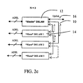
FIG. 2c is a block diagram of an exemplary embodiment of the invention for N=3; -
FIG. 2d is a block diagram of an exemplary embodiment of the invention for N=7; -
FIG. 3 is a schematic diagram illustrating the traffic redirection capability of the redundant structure of the present invention; -
FIG. 4 is a schematic diagram of dual master stacking possible with the present invention; -
FIG. 5 is a detailed schematic diagram of the main functional blocks of the master and slave DSLAMs in a configuration according to the present invention; -
FIG. 6 is a schematic demonstration of an embodiment for communications between DSLAMs employing the present invention; -
FIG. 7 shows an example of the relay/stacking I/O table in a Slave DSLAM; -
FIG. 8 illustrates an example of the proxy table in the Master for the embodiment ofFIG. 2d with N=7; -
FIG. 9 illustrates the communications relaying scheme for the Slaves' downlink path; -
FIG. 10 illustrates the communications relaying scheme for the Slaves' uplink path; -
FIG. 11 is a flow chart depicting ATM uplink communications in an embodiment of the invention; -
FIG. 12 is a flow chart depicting ATM downlink communications in an embodiment of the invention; and, -
FIG. 13 is a state diagram for in-band communications in an embodiment of the invention. - The proposed method improves the conventional stacking approach by providing dual links between the master and slave boxes in a "ring" structure, such that redundancy is built-in and software controllable. Further, the data path route from master to slave is also software configurable.
FIGs. 2a and b show the proposed new method of stacking based on "ring" or "dual link" architecture respectively. Thestacking link 10 connecting themaster box 12 andslave boxes 14 for the embodiments shown is based on low voltage differential signaling (LVDS) technology, designed to carry ATM traffic, as will be discussed in greater detail subsequently. The concept, however, can apply for other types of links. For illustration purposes, theuplink 16 for data traffic is shown as ATM based connecting to the central office (CO) or ATM network via OC-3 or (Multilink) E1/T1 IMA. In the "ring" structure with "round robin" data communication configuration shown inFIG. 2a , the data flows in one direction from one box to another (i.e. to the one stacked below). The last box down the chain completes the "ring" by following the same data path to the master. In the "dual link" structure with "split path" data communication configuration, the data flows bi-directionally (transmit/receive) from one box to another (i.e. to the one stacked below). The master splits the two traffic paths via software control, based either on virtual slave box identification numbers and/or ATM virtual path/virtual circuit numbers of a slave box. - The configuration described is further illustrated in
FIGs 2c and2d for N = 3 and N = 7 respectively. Here, the Master to Slave and Slave to Slave interconnections alternate in each link, as shown. In one link, for example, the chain connection order is from Master to Slave 1 toSlave 3, etc. In the other link, the chain order is from Master to Slave 2 toSlave 4, etc. The last two slave boxes in each chain link then connect with each other on link 10' to complete the loop for the purpose of redundancy and traffic redirection in case a failure occurs as will be described in greater detail subsequently. - An additional alternative or simple dual link connection will be the same as shown in
FIG 2a , but the traffic path is reprogrammed by the Master to be bi-directional on each link. The two paths will be, for an example of N=7, (a) Master toSlave Slave Slave 3 andSlave 4 will not be used for data traffic but for redundancy. - A third alternative provides the two slave boxes connecting to the Master are the first Slave and a middle slave. In case of N=3, the middle slave will #2. One link connects Master and Slave 1, and the other link connects Master and Slave 2 and then Slave 3. For N=7, the middle slave will be 4 and one link will be Master and
Slave 1 and then 2 and 3. The other link will be Master andSlave 4, and then 5 to 7. Again, the loop closes by linking togetherSlaves Slaves - The flexibility of the invention allows this configuration to also be used for a Round Robin daisy chain link since the virtual "position" of the slave DSLAMs is programmable. The data path can be programmed at the initialization phase to be unidirectional on the link, i.e., in the order of Master to
Slave 1 toSlave 3 toSlave 2 to Master for N = 3, and Master toSlave 1 toSlave 3 toSlave 5 toSlave 7 toSlave 6 toSlave 4 toSlave 2 to Master for N = 7. In this case, the last link (10') will also be used for data traffic. The link path can be reconfigured by the Master to bi-directional as shown inFIG. 2d when a failure occurs. -
FIG. 3 shows an example of the reliability feature or self-healing available with the method of the present invention. As shown for a ring stack chain physical configuration, one slave box 14' going down will not affect the operation of the rest of the stacked boxes. The master can redirect traffic when informed the failure has occurred in one of the slave boxes by converting the traffic in the slave boxes to split path with bi-direction communication on both sides of the "down" slave box with communication to the master box at both ends of the chain. For the configurations described above with respect toFIGs. 2c and2d , the link 10' is activated for normal communication. - Detecting a failure/malfunction of a slave DSLAM is accomplished by the Master for the embodiments shown in one of several approaches. A first approach is for Master to periodically send a "heart-beat" message to each slave by means of polling in a round robin fashion. If the slave being polled (identified by virtual ID) does not respond within a pre-designated time, the Master will consider it has failed and redirect traffic around that slave.
- A second approach is that the slaves communicate with each other by sending heart-beat messages. As an example, the architecture can be programmed by the Master such that the box that is stacked "on top" always sends messages to the one that is stacked "below" or next in communication sequence. In the round-robin chain case, the Master sends heart-beat to
Slave 1,Slave 1 sends the heart-beat toSlave 2 and so on. When the box receiving the heart-beat message does not respond within a pre-designated time, the box sending the message will consider that box being failed and inform the Master using the reserved in-band communication channel (as described below). -
FIG. 4 shows an embodiment of the present invention with a dual master configuration with asecond master box 18, providing full protection in the event one master fails. Coordination between the two masters is employed, in terms of traffic and configuration, such as active/standby, shared active/active, etc. -
FIG. 5 shows the internal main functional architecture of the master and slave DSLAMs and a general stacking arrangement. The master box incorporates multiple ADSL interfaces 20 for connection to the user lines 22. Acontrol circuit 24 with a central processing unit (CPU) and ATM switching and traffic management controls the master DSLAM. Anuplink circuit 26 provides communication with the CO using STM/OC3 or multilink EI/TI IMA. Communication with the slave boxes is provided bymultiple LVDS circuits - Each slave box also has multiple ADSL interfaces 30 for connection to the user lines 32. A
control circuit 34 with a central processing unit (CPU) and ATM switching and traffic management controls the slave DSLAM under software control by the master.LVDS ports FIG. 3 . - The communications between the Master and Slaves and between the Slave DSLAMs for the embodiments shown are based on in-band communications carried within the LVDS link and ATM cell streams. This is also the CPU to CPU communication means between two DSLAM boxes via an in-band LVDS channel.
FIG. 6 demonstrates this embodiment in schematic form. The CPU messages are inserted into the ATM cell streams by the LVDS circuit through the CPU interface as represented bylinks 40. The in-band communications are transmitted by the LVDS with the ATM cell streams onlinks 10 between DSLAMs. - Communication between the master and slave boxes employs a proxy and/or relaying traffic mechanism/scheme for data and management messages, based on virtual box identification and virtual path/circuit identifications. Each Slave DSLAM maintains a traffic relay and stacking I/O table that does the virtual channel and box ID mapping. The table is updated whenever instructed by the Master via in-band communication channel.
FIG. 7 shows an example of the relay/stacking I/O table in a Slave DSLAM. The table incorporates the ADSL port numbers connected to the DSLAM, the VCI/VPIs for the Slave DSLAM, the virtual ID for the DSLAM and the Stacking Input/Output mode for each of the two LVDS ports. The stacking ports in the Utopia LVDS configuration shown for the embodiments in the drawings can be predefined as belonging to the "A" or "B" LVDS link during initialization. Each port can be programmed for input, output or bi-directional (input and output) communication. - The Master DSLAM maintains a "proxy" table for all slaves, which includes VCI/VPI cross-connect information and mapping between external VCI/VPI to internal (slave) VCI/VPI, as well as stacking I/O configuration.
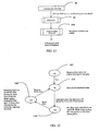
FIG. 8 illustrates an example of the proxy table in the Master for the embodiment ofFIG. 2d with N=7. The proxy table contains the information present in the tables for each of the Slaves and an additional data item defining the Master Stacking Mode for round robin or split path. The Stacking Input/Output mode established by the Master will be determined by the Stacking mode as previously described. Failure mode recovery can be accomplished by the Master as previously described resulting in a change in the Stacking mode and bypassing of a failed Slave DSLAM in the communications path. - The communications relaying scheme for the Slaves is illustrated in
FIGs. 9 and10 for downlink and uplink paths respectively. Referring toFIG. 9 , the ATM data from the uplink is received by a DSLAM inblock 50 and routed through anATM switch 52. A determination is made inblock 54 comparing the ATM cells with the DSLAM traffic relay and stacking table to determine if the communication is local or should be downlinked in the stack. If the communication is intended for an ADSL port in the DSLAM, it is switched to the appropriate local ADSL port inblock 56. If the communication is to be passed through, a check of the stacking I/O table is made to determine the transfer port inblock 58. If the I/O table has been updated, the communication is passed to the new stacking port inblock 60 for ATM output to the next DSLAM as defined by the new stacking port data. If the I/O table has not been updated, the communication is passed to the old stacking port inblock 62 for ATM output to the next DSLAM as defined by the old stacking port data. - Uplinking of data is shown in
FIG. 10 where ATM data from the Downlink is received inblock 64 from the local ADSL ports in the DSLAM or from the stacking input port. The data is routed through theATM switch 66 and to theuplink switch 68 for external communication. A check of the stacking I/O table is made to determine the transfer port inblock 70. If the I/O table has not been updated, the communication is passed to the old stacking port inblock 72 for ATM output to the next DSLAM as defined by the old stacking port data. If the I/O table has been updated, the communication is passed to the new stacking port inblock 74 for ATM output to the next DSLAM as defined by the new stacking port data. - Uplink and downlink communications for the Master DSLAM are conducted based on the proxy table previously described with respect to
FIG. 8 . As shown inFIG. 11 , ATM data is received by the Master from the uplink inblock 80 through theATM switch 82. Adetermination 84 is made whether the ATM cells correspond to a local ADSL port for the Master or require a stack downlink. If local the ATM cells are switched to the appropriate local DSL port inblock 86, if not, acheck 88 is made to determine the stacking mode. If a determination is made inblock 90 that the round robin mode is present, the Master switches to the output stacking port previously defined inblock 92. The proxy table allows conversion of the external VCI/VPI to internal (slave) VCI/VPI for downlink. If a split mode is used, a switch to the proper stacking port is made using the VCI/VPI cross connect table inblock 94. - The uplink proxy path is shown in
FIG. 12 . ATM data from the local ADSL port in the Master or downlink slave DSLAM is received inblock 96 through theATM switch 98 and transmitted through the uplink inswitch 100 with the Master conducting the VCI/VPI cross connect as required pursuant to the proxy table. - Heartbeat communications and failure reprogramming are accomplished by the Master DSLAM using inband messaging as previously described. For the case of a Round-Robin chain link in the embodiments shown, the failure sensing schemes reserve the in-band communication channel that is in the reverse direction of the normal ATM traffic, in order to inform the Master when failure occurs. For the case of split-path chain link, however, since each link is already bi-directional, the in-band communication channel is carried over the normal ATM traffic.
- The Master reprograms the Slave path direction in case of failure through the in-band communication channel by sending down stacking path I/O messages to each of the Slave boxes (minus the failed one). The Slave boxes then update their corresponding I/O tables. The Master incorporates a simple state machine that tracks the operating condition of each Slave box in its stacking control circuit.
- Similarly, when the failed DSLAM box is recovered to be operational again, it will inform the Master through the in-band communication channel to notify that it is alive. The Master then will either update the I/O table of all the Slaves including the recovered one, or by updating only the recovered Slave of its normal traffic I/O path that follows the rest of the traffic directions.
- The state machine for the described in-band communications is shown in
FIG. 13 . At start-up, the Master sends aninitialization communication 102 to define the stacking I/O information table for each DSLAM. As long as all Slaves remain operational,state 104, in response to heartbeat signals, communications proceed based on the initialized settings. If no heart-beat response is received or a failure notification is received, the Master entersstate 106, identifies the failed Slave by its virtual ID and sends stacking I/O table updates to the remaining operational slaves. The remaining Slaves continue operation with the revised I/O stacking tables until the failed Slave communicates with the Master that it is recovered. Upon such notification, the Master entersstate 108 and again sends updated stacking I/O table information to all Slaves in the stack before returning to theOperational state 104. - Having now described the invention in detail as required by the patent statutes, those skilled in the art will recognize modifications and substitutions to the specific embodiments disclosed herein. Such modifications are within the scope of the present invention as defined in the following claims.
Claims (15)
- An architecture for stacking Digital Subscriber Line Access Multiplexers, DSLAMs, comprising:a master DSLAM (12) having a control circuit and two low voltage differential signaling, LVDS, circuits for communication with two DSLAMs in direct adjacent circuit interconnection to the master DSLAM (12);a plurality of slave DSLAMs (14) each having a programmable control circuit and two LVDS circuits for communication with two DSLAMs in adjacent virtual circuit interconnection; andmeans for selectively programming the control circuit in each slave DSLAM (14) to control a direction of communication in the LVDS circuits in each said slave DSLAM, (14) as round robin in a first selected mode and a split path in a second selected mode.
- An architecture for stacking DSLAMs as defined in claim 1 wherein the two DSLAMs in adjacent circuit connection to the master are a first and a last slave DSLAMs (14) to form a ring structure.
- An architecture for stacking DSLAMs as defined in claim 1 wherein the two DSLAMs in direct adjacent circuit connection to the master (12) are a first and a middle slave DSLAMs (14) to form a dual link structure.
- An architecture for stacking DSLAMs as defined in claim 1 wherein the means for selectively programming the slave DSLAMs (14) employs a proxy scheme for data and management messages, based on virtual box identification and virtual path/circuit identifications.
- An architecture for stacking DSLAMs as defined in claim 1 wherein the means for selectively programming the slave DSLAMs (14) employs a relaying traffic mechanism for data and management messages, based on virtual box identification and virtual path/circuit identifications.
- An architecture for stacking DSLAMs as defined in claim 1 further comprising means for detecting failure of one of the slave DSLAMs (14) and wherein the means for selectively programming is responsive to the means for detecting failure to allow reprogramming from a round robin to split path communication around the failed slave DSLAM (14).
- An architecture for stacking DSLAMs as defined in claim 1 wherein said split path is selectively programmed at an adjacent virtual circuit connection.
- An architecture for stacking DSLAMs as defined in claim 1 wherein said master DSLAM further includes an uplink communication circuit (16) to a central office (CO).
- A method for operating an architecture that stacks Digital Subscriber Line Access Multiplexers, DSLAMs, the method comprising:using a control circuit of a master DSLAM to selectively program a control circuit in each of a plurality of slave DSLAMs to control a direction of communication in low voltage differential signaling, LVDS, circuits in said each slave DSLAM as round robin in a first selected mode; andif a failure in at least one of said slave DSLAMs is detected, using said control circuit of said master DSLAM to selectively program said control circuit in particular ones of the slave DSLAMs to control the direction of communication in the LVDS circuits as a split path in a second selected mode.
- A method for operating an architecture as defined in claim 9, wherein the two DSLAMs in adjacent circuit connection to the master are a first and last slave DSLAM formed as a ring structure.
- A method for operating an architecture as defined in claim 9, wherein the two DSLAMs in adjacent circuit connection to the master are a first and middle slave DSLAMs formed as a dual link structure.
- A method for operating an architecture as defined in claim 9, wherein selective programming of the slave DSLAM is a proxy scheme for data and management messages, based on virtual box identification and virtual path/circuit identifications.
- A method for operating an architecture as defined in claim 9, wherein selective programming of the slave DSLAM is a relaying traffic mechanism for data and management messages based on virtual box identification and virtual path/circuit.
- A method for operating an architecture as defined in claim 9, wherein detecting failure of one of the slave DSLAMs (14) and selective programming is responsive to the means for detecting failure to allow reprogramming from a round to split path around the failed slave DSLAM (14).
- A method for operating an architecture as defined in claim 9, wherein said split path is selectively programmed at an adjacent virtual circuit connection.
Applications Claiming Priority (3)
| Application Number | Priority Date | Filing Date | Title |
|---|---|---|---|
| US346485 | 2003-01-16 | ||
| US10/346,485 US7116674B2 (en) | 2003-01-16 | 2003-01-16 | Method and apparatus for digital subscriber line access multiplexer stacking |
| PCT/US2004/000262 WO2004066107A2 (en) | 2003-01-16 | 2004-01-06 | Method and apparatus for digital subscriber line access multiplexer stacking |
Publications (3)
| Publication Number | Publication Date |
|---|---|
| EP1584150A2 EP1584150A2 (en) | 2005-10-12 |
| EP1584150A4 EP1584150A4 (en) | 2006-10-18 |
| EP1584150B1 true EP1584150B1 (en) | 2011-09-14 |
Family
ID=32712160
Family Applications (1)
| Application Number | Title | Priority Date | Filing Date |
|---|---|---|---|
| EP04700392A Expired - Lifetime EP1584150B1 (en) | 2003-01-16 | 2004-01-06 | Method and apparatus for digital subscriber line access multiplexer stacking |
Country Status (5)
| Country | Link |
|---|---|
| US (1) | US7116674B2 (en) |
| EP (1) | EP1584150B1 (en) |
| JP (1) | JP4499089B2 (en) |
| AT (1) | ATE524889T1 (en) |
| WO (1) | WO2004066107A2 (en) |
Cited By (2)
| Publication number | Priority date | Publication date | Assignee | Title |
|---|---|---|---|---|
| US9491097B2 (en) | 2012-10-17 | 2016-11-08 | Hewlett Packard Enterprise Development Lp | Packet forwarding in a star stacking system |
| CN106550060A (en) * | 2016-10-28 | 2017-03-29 | 杭州华三通信技术有限公司 | A kind of network management interface address distribution method and device |
Families Citing this family (25)
| Publication number | Priority date | Publication date | Assignee | Title |
|---|---|---|---|---|
| US7009977B1 (en) * | 2000-06-09 | 2006-03-07 | Conklin Corporation | Method and system for expanding services in a digital loop carrier system |
| WO2005086755A2 (en) * | 2004-03-10 | 2005-09-22 | Scaleout Software, Inc. | Scalable, highly available cluster membership architecture |
| US7346051B2 (en) * | 2004-06-25 | 2008-03-18 | Matsushita Electric Industrial Co., Ltd. | Slave device, master device and stacked device |
| US7433365B1 (en) * | 2004-08-31 | 2008-10-07 | Adtran, Inc. | System architecture for linking channel banks of a data communication system |
| US7440393B2 (en) * | 2004-12-09 | 2008-10-21 | Scalent Systems, Inc. | Method and system for managing communication in a data network |
| CN100361470C (en) | 2004-12-30 | 2008-01-09 | 华为技术有限公司 | The Method of Using Slave Box to Realize Multicast in Digital Subscriber Line Access |
| JP4106632B2 (en) * | 2005-01-31 | 2008-06-25 | 富士通株式会社 | Communication apparatus and communication control method |
| US20070097870A1 (en) * | 2005-11-01 | 2007-05-03 | Bakri Aboukarr | Remote control and control redundancy for distributed communication equipment |
| US7860968B2 (en) * | 2005-11-21 | 2010-12-28 | Sap Ag | Hierarchical, multi-tiered mapping and monitoring architecture for smart items |
| US8005879B2 (en) | 2005-11-21 | 2011-08-23 | Sap Ag | Service-to-device re-mapping for smart items |
| US8156208B2 (en) | 2005-11-21 | 2012-04-10 | Sap Ag | Hierarchical, multi-tiered mapping and monitoring architecture for service-to-device re-mapping for smart items |
| DE102005058982B4 (en) * | 2005-12-09 | 2008-02-28 | Infineon Technologies Ag | Bundling circuit for a line driver card and method for bundling data fragments |
| US8522341B2 (en) | 2006-03-31 | 2013-08-27 | Sap Ag | Active intervention in service-to-device mapping for smart items |
| US8065411B2 (en) | 2006-05-31 | 2011-11-22 | Sap Ag | System monitor for networks of nodes |
| US8131838B2 (en) * | 2006-05-31 | 2012-03-06 | Sap Ag | Modular monitor service for smart item monitoring |
| US8296413B2 (en) | 2006-05-31 | 2012-10-23 | Sap Ag | Device registration in a hierarchical monitor service |
| DE102006033639A1 (en) * | 2006-07-20 | 2008-01-24 | Robert Bosch Gmbh | Electronic device for connection to an optical data bus and method |
| US8396788B2 (en) | 2006-07-31 | 2013-03-12 | Sap Ag | Cost-based deployment of components in smart item environments |
| EP2061267A4 (en) * | 2006-09-06 | 2011-01-12 | Mitsubishi Electric Corp | DATA RETRANSMISSION METHOD, DERESE CONTROL DEVICE, MOBILE STATION, AND BASE STATION |
| US20080080391A1 (en) * | 2006-09-29 | 2008-04-03 | Sbc Knowledge Ventures, L.P. | Method and apparatus for supporting an asymmetric transport network |
| US8259707B2 (en) * | 2006-10-17 | 2012-09-04 | Generonix, Inc. | Wireless access point network system supported through existing transmission lines |
| EP2084863B1 (en) * | 2006-11-09 | 2012-05-02 | Telefonaktiebolaget LM Ericsson (publ) | Switching node, transmission network and method relating to identification of hardware units |
| US8527622B2 (en) * | 2007-10-12 | 2013-09-03 | Sap Ag | Fault tolerance framework for networks of nodes |
| US8780915B2 (en) | 2009-06-26 | 2014-07-15 | Telekom Malaysia Berhad | Method and system for tagging packets routed to customer premises devices via clusters of dedicated customer interfaces |
| KR102766658B1 (en) * | 2019-09-06 | 2025-02-12 | 에스케이하이닉스 주식회사 | Semiconductor device |
Family Cites Families (7)
| Publication number | Priority date | Publication date | Assignee | Title |
|---|---|---|---|---|
| US5914957A (en) * | 1996-12-19 | 1999-06-22 | Otis Elevator Company | Automatic node configuration with identical nodes |
| JP2000312207A (en) * | 1999-04-27 | 2000-11-07 | Mitsubishi Electric Corp | Communications system |
| US6801533B1 (en) * | 1999-12-09 | 2004-10-05 | Cisco Technology, Inc. | System and method for proxy signaling in a digital subscriber line access multiplexer (DSLAM) |
| US6680904B1 (en) * | 1999-12-27 | 2004-01-20 | Orckit Communications Ltd. | Bi-directional chaining of network access ports |
| US6834038B1 (en) * | 2000-08-11 | 2004-12-21 | Orckit Communications Ltd. | Protection against master unit failure in remote network access multiplexing |
| US6822944B1 (en) * | 2000-11-08 | 2004-11-23 | Orckit Communications Ltd. | Management interface for a network access multiplexing system |
| US7009939B2 (en) * | 2001-05-21 | 2006-03-07 | Lucent Technologies Inc. | Adaptive resource management in a communication system |
-
2003
- 2003-01-16 US US10/346,485 patent/US7116674B2/en not_active Expired - Lifetime
-
2004
- 2004-01-06 WO PCT/US2004/000262 patent/WO2004066107A2/en not_active Ceased
- 2004-01-06 JP JP2006500811A patent/JP4499089B2/en not_active Expired - Fee Related
- 2004-01-06 AT AT04700392T patent/ATE524889T1/en not_active IP Right Cessation
- 2004-01-06 EP EP04700392A patent/EP1584150B1/en not_active Expired - Lifetime
Cited By (3)
| Publication number | Priority date | Publication date | Assignee | Title |
|---|---|---|---|---|
| US9491097B2 (en) | 2012-10-17 | 2016-11-08 | Hewlett Packard Enterprise Development Lp | Packet forwarding in a star stacking system |
| DE112013001512B4 (en) * | 2012-10-17 | 2018-05-03 | Hewlett Packard Enterprise Development Lp | Packet forwarding against a background of a star topology stacking system |
| CN106550060A (en) * | 2016-10-28 | 2017-03-29 | 杭州华三通信技术有限公司 | A kind of network management interface address distribution method and device |
Also Published As
| Publication number | Publication date |
|---|---|
| US20040141609A1 (en) | 2004-07-22 |
| JP4499089B2 (en) | 2010-07-07 |
| EP1584150A4 (en) | 2006-10-18 |
| WO2004066107A3 (en) | 2005-04-28 |
| WO2004066107A2 (en) | 2004-08-05 |
| US7116674B2 (en) | 2006-10-03 |
| EP1584150A2 (en) | 2005-10-12 |
| JP2006518950A (en) | 2006-08-17 |
| ATE524889T1 (en) | 2011-09-15 |
Similar Documents
| Publication | Publication Date | Title |
|---|---|---|
| US7116674B2 (en) | Method and apparatus for digital subscriber line access multiplexer stacking | |
| US6680904B1 (en) | Bi-directional chaining of network access ports | |
| JPS60176346A (en) | Ring type signal transmitting network | |
| JP3001502B2 (en) | ATM switch module, ATM switch capacity expansion method, and ATM routing information setting method | |
| CN1330473A (en) | Spare redundance in backward multiservice | |
| JPH0118636B2 (en) | ||
| US6603736B1 (en) | Communication device for transmitting message signals | |
| EP1716498B1 (en) | Restoration mechanism for network topologies | |
| JP3008850B2 (en) | Network server redundant configuration method | |
| US4625082A (en) | Local area network communications system for maintaining service in the event of a fault | |
| CN100449983C (en) | Method and communication device for implementing at least one fail-safe communication link | |
| May et al. | A fast restoration system for ATM-ring-based LANs | |
| AU1223299A (en) | Communication device for the transmission of message signals | |
| JP3139424B2 (en) | TST 3-stage switch control system | |
| KR960027838A (en) | Signal Processing Method in ATM Switching Network, ATM Switching System and ATM Switching Network Controlling Transmission of Input Cell by Control Cell | |
| JP3881716B2 (en) | Communication network for communication signal transmission | |
| JP4372078B2 (en) | Gateway device | |
| KR100344024B1 (en) | Dual ATM Router by using cell bus in ATM system | |
| JPH1065696A (en) | Communication network and failure notification method | |
| JP2862661B2 (en) | Detour / switchback control method in ATM network | |
| US6944124B2 (en) | Bypass control system based upon NMS control in ATM exchanger | |
| JP2001268101A (en) | Network system | |
| JP3657856B2 (en) | Communications system | |
| JP2002208941A (en) | Pvc switching control method for atm network | |
| KR0179585B1 (en) | Cel bus duplication apparatus in subscriber matching module of atm-mss |
Legal Events
| Date | Code | Title | Description |
|---|---|---|---|
| PUAI | Public reference made under article 153(3) epc to a published international application that has entered the european phase |
Free format text: ORIGINAL CODE: 0009012 |
|
| 17P | Request for examination filed |
Effective date: 20050728 |
|
| AK | Designated contracting states |
Kind code of ref document: A2 Designated state(s): AT BE BG CH CY CZ DE DK EE ES FI FR GB GR HU IE IT LI LU MC NL PT RO SE SI SK TR |
|
| AX | Request for extension of the european patent |
Extension state: AL LT LV MK |
|
| DAX | Request for extension of the european patent (deleted) | ||
| A4 | Supplementary search report drawn up and despatched |
Effective date: 20060920 |
|
| RIC1 | Information provided on ipc code assigned before grant |
Ipc: H04L 12/56 20060101ALI20060914BHEP Ipc: H04J 3/08 20060101AFI20050517BHEP |
|
| 17Q | First examination report despatched |
Effective date: 20090325 |
|
| GRAP | Despatch of communication of intention to grant a patent |
Free format text: ORIGINAL CODE: EPIDOSNIGR1 |
|
| GRAS | Grant fee paid |
Free format text: ORIGINAL CODE: EPIDOSNIGR3 |
|
| GRAA | (expected) grant |
Free format text: ORIGINAL CODE: 0009210 |
|
| AK | Designated contracting states |
Kind code of ref document: B1 Designated state(s): AT BE BG CH CY CZ DE DK EE ES FI FR GB GR HU IE IT LI LU MC NL PT RO SE SI SK TR |
|
| REG | Reference to a national code |
Ref country code: CH Ref legal event code: EP |
|
| REG | Reference to a national code |
Ref country code: IE Ref legal event code: FG4D |
|
| REG | Reference to a national code |
Ref country code: DE Ref legal event code: R096 Ref document number: 602004034309 Country of ref document: DE Effective date: 20111110 |
|
| REG | Reference to a national code |
Ref country code: NL Ref legal event code: VDEP Effective date: 20110914 |
|
| PG25 | Lapsed in a contracting state [announced via postgrant information from national office to epo] |
Ref country code: SE Free format text: LAPSE BECAUSE OF FAILURE TO SUBMIT A TRANSLATION OF THE DESCRIPTION OR TO PAY THE FEE WITHIN THE PRESCRIBED TIME-LIMIT Effective date: 20110914 Ref country code: FI Free format text: LAPSE BECAUSE OF FAILURE TO SUBMIT A TRANSLATION OF THE DESCRIPTION OR TO PAY THE FEE WITHIN THE PRESCRIBED TIME-LIMIT Effective date: 20110914 |
|
| PG25 | Lapsed in a contracting state [announced via postgrant information from national office to epo] |
Ref country code: SI Free format text: LAPSE BECAUSE OF FAILURE TO SUBMIT A TRANSLATION OF THE DESCRIPTION OR TO PAY THE FEE WITHIN THE PRESCRIBED TIME-LIMIT Effective date: 20110914 Ref country code: CY Free format text: LAPSE BECAUSE OF FAILURE TO SUBMIT A TRANSLATION OF THE DESCRIPTION OR TO PAY THE FEE WITHIN THE PRESCRIBED TIME-LIMIT Effective date: 20110914 Ref country code: AT Free format text: LAPSE BECAUSE OF FAILURE TO SUBMIT A TRANSLATION OF THE DESCRIPTION OR TO PAY THE FEE WITHIN THE PRESCRIBED TIME-LIMIT Effective date: 20110914 Ref country code: GR Free format text: LAPSE BECAUSE OF FAILURE TO SUBMIT A TRANSLATION OF THE DESCRIPTION OR TO PAY THE FEE WITHIN THE PRESCRIBED TIME-LIMIT Effective date: 20111215 |
|
| REG | Reference to a national code |
Ref country code: AT Ref legal event code: MK05 Ref document number: 524889 Country of ref document: AT Kind code of ref document: T Effective date: 20110914 |
|
| PG25 | Lapsed in a contracting state [announced via postgrant information from national office to epo] |
Ref country code: BE Free format text: LAPSE BECAUSE OF FAILURE TO SUBMIT A TRANSLATION OF THE DESCRIPTION OR TO PAY THE FEE WITHIN THE PRESCRIBED TIME-LIMIT Effective date: 20110914 |
|
| PG25 | Lapsed in a contracting state [announced via postgrant information from national office to epo] |
Ref country code: CZ Free format text: LAPSE BECAUSE OF FAILURE TO SUBMIT A TRANSLATION OF THE DESCRIPTION OR TO PAY THE FEE WITHIN THE PRESCRIBED TIME-LIMIT Effective date: 20110914 Ref country code: SK Free format text: LAPSE BECAUSE OF FAILURE TO SUBMIT A TRANSLATION OF THE DESCRIPTION OR TO PAY THE FEE WITHIN THE PRESCRIBED TIME-LIMIT Effective date: 20110914 |
|
| PG25 | Lapsed in a contracting state [announced via postgrant information from national office to epo] |
Ref country code: IT Free format text: LAPSE BECAUSE OF FAILURE TO SUBMIT A TRANSLATION OF THE DESCRIPTION OR TO PAY THE FEE WITHIN THE PRESCRIBED TIME-LIMIT Effective date: 20110914 Ref country code: PT Free format text: LAPSE BECAUSE OF FAILURE TO SUBMIT A TRANSLATION OF THE DESCRIPTION OR TO PAY THE FEE WITHIN THE PRESCRIBED TIME-LIMIT Effective date: 20120116 Ref country code: EE Free format text: LAPSE BECAUSE OF FAILURE TO SUBMIT A TRANSLATION OF THE DESCRIPTION OR TO PAY THE FEE WITHIN THE PRESCRIBED TIME-LIMIT Effective date: 20110914 Ref country code: RO Free format text: LAPSE BECAUSE OF FAILURE TO SUBMIT A TRANSLATION OF THE DESCRIPTION OR TO PAY THE FEE WITHIN THE PRESCRIBED TIME-LIMIT Effective date: 20110914 Ref country code: NL Free format text: LAPSE BECAUSE OF FAILURE TO SUBMIT A TRANSLATION OF THE DESCRIPTION OR TO PAY THE FEE WITHIN THE PRESCRIBED TIME-LIMIT Effective date: 20110914 |
|
| PLBE | No opposition filed within time limit |
Free format text: ORIGINAL CODE: 0009261 |
|
| STAA | Information on the status of an ep patent application or granted ep patent |
Free format text: STATUS: NO OPPOSITION FILED WITHIN TIME LIMIT |
|
| PG25 | Lapsed in a contracting state [announced via postgrant information from national office to epo] |
Ref country code: DK Free format text: LAPSE BECAUSE OF FAILURE TO SUBMIT A TRANSLATION OF THE DESCRIPTION OR TO PAY THE FEE WITHIN THE PRESCRIBED TIME-LIMIT Effective date: 20110914 |
|
| 26N | No opposition filed |
Effective date: 20120615 |
|
| PG25 | Lapsed in a contracting state [announced via postgrant information from national office to epo] |
Ref country code: MC Free format text: LAPSE BECAUSE OF NON-PAYMENT OF DUE FEES Effective date: 20120131 |
|
| REG | Reference to a national code |
Ref country code: CH Ref legal event code: PL |
|
| REG | Reference to a national code |
Ref country code: DE Ref legal event code: R097 Ref document number: 602004034309 Country of ref document: DE Effective date: 20120615 |
|
| REG | Reference to a national code |
Ref country code: IE Ref legal event code: MM4A |
|
| PG25 | Lapsed in a contracting state [announced via postgrant information from national office to epo] |
Ref country code: LI Free format text: LAPSE BECAUSE OF NON-PAYMENT OF DUE FEES Effective date: 20120131 Ref country code: CH Free format text: LAPSE BECAUSE OF NON-PAYMENT OF DUE FEES Effective date: 20120131 |
|
| PG25 | Lapsed in a contracting state [announced via postgrant information from national office to epo] |
Ref country code: IE Free format text: LAPSE BECAUSE OF NON-PAYMENT OF DUE FEES Effective date: 20120106 |
|
| PG25 | Lapsed in a contracting state [announced via postgrant information from national office to epo] |
Ref country code: ES Free format text: LAPSE BECAUSE OF FAILURE TO SUBMIT A TRANSLATION OF THE DESCRIPTION OR TO PAY THE FEE WITHIN THE PRESCRIBED TIME-LIMIT Effective date: 20111225 |
|
| PG25 | Lapsed in a contracting state [announced via postgrant information from national office to epo] |
Ref country code: BG Free format text: LAPSE BECAUSE OF FAILURE TO SUBMIT A TRANSLATION OF THE DESCRIPTION OR TO PAY THE FEE WITHIN THE PRESCRIBED TIME-LIMIT Effective date: 20111214 |
|
| PG25 | Lapsed in a contracting state [announced via postgrant information from national office to epo] |
Ref country code: TR Free format text: LAPSE BECAUSE OF FAILURE TO SUBMIT A TRANSLATION OF THE DESCRIPTION OR TO PAY THE FEE WITHIN THE PRESCRIBED TIME-LIMIT Effective date: 20110914 |
|
| PG25 | Lapsed in a contracting state [announced via postgrant information from national office to epo] |
Ref country code: LU Free format text: LAPSE BECAUSE OF NON-PAYMENT OF DUE FEES Effective date: 20120106 |
|
| PG25 | Lapsed in a contracting state [announced via postgrant information from national office to epo] |
Ref country code: HU Free format text: LAPSE BECAUSE OF FAILURE TO SUBMIT A TRANSLATION OF THE DESCRIPTION OR TO PAY THE FEE WITHIN THE PRESCRIBED TIME-LIMIT Effective date: 20040106 |
|
| REG | Reference to a national code |
Ref country code: FR Ref legal event code: PLFP Year of fee payment: 13 |
|
| REG | Reference to a national code |
Ref country code: FR Ref legal event code: PLFP Year of fee payment: 14 |
|
| REG | Reference to a national code |
Ref country code: FR Ref legal event code: PLFP Year of fee payment: 15 |
|
| PGFP | Annual fee paid to national office [announced via postgrant information from national office to epo] |
Ref country code: GB Payment date: 20221214 Year of fee payment: 20 Ref country code: FR Payment date: 20221216 Year of fee payment: 20 |
|
| PGFP | Annual fee paid to national office [announced via postgrant information from national office to epo] |
Ref country code: DE Payment date: 20221215 Year of fee payment: 20 |
|
| REG | Reference to a national code |
Ref country code: DE Ref legal event code: R071 Ref document number: 602004034309 Country of ref document: DE |
|
| REG | Reference to a national code |
Ref country code: GB Ref legal event code: PE20 Expiry date: 20240105 |
|
| PG25 | Lapsed in a contracting state [announced via postgrant information from national office to epo] |
Ref country code: GB Free format text: LAPSE BECAUSE OF EXPIRATION OF PROTECTION Effective date: 20240105 |