EP1113697A2 - Bi-directional chaining of network access ports - Google Patents
Bi-directional chaining of network access ports Download PDFInfo
- Publication number
- EP1113697A2 EP1113697A2 EP00308662A EP00308662A EP1113697A2 EP 1113697 A2 EP1113697 A2 EP 1113697A2 EP 00308662 A EP00308662 A EP 00308662A EP 00308662 A EP00308662 A EP 00308662A EP 1113697 A2 EP1113697 A2 EP 1113697A2
- Authority
- EP
- European Patent Office
- Prior art keywords
- packets
- slave
- master
- network
- switch
- Prior art date
- Legal status (The legal status is an assumption and is not a legal conclusion. Google has not performed a legal analysis and makes no representation as to the accuracy of the status listed.)
- Withdrawn
Links
- 241000723353 Chrysanthemum Species 0.000 claims abstract description 17
- 235000005633 Chrysanthemum balsamita Nutrition 0.000 claims abstract description 17
- 238000011144 upstream manufacturing Methods 0.000 claims description 42
- 239000004744 fabric Substances 0.000 claims description 30
- 238000000034 method Methods 0.000 claims description 18
- 230000000717 retained effect Effects 0.000 claims description 8
- 230000004044 response Effects 0.000 claims description 7
- 230000005540 biological transmission Effects 0.000 claims description 6
- 238000012546 transfer Methods 0.000 claims description 6
- 230000008878 coupling Effects 0.000 claims description 4
- 238000010168 coupling process Methods 0.000 claims description 4
- 238000005859 coupling reaction Methods 0.000 claims description 4
- 238000010586 diagram Methods 0.000 description 21
- 238000004891 communication Methods 0.000 description 4
- 230000009471 action Effects 0.000 description 3
- 230000000694 effects Effects 0.000 description 3
- 230000008672 reprogramming Effects 0.000 description 3
- 238000001514 detection method Methods 0.000 description 2
- 230000007246 mechanism Effects 0.000 description 2
- 230000008569 process Effects 0.000 description 2
- 239000004820 Pressure-sensitive adhesive Substances 0.000 description 1
- 230000008901 benefit Effects 0.000 description 1
- 230000002457 bidirectional effect Effects 0.000 description 1
- 239000000872 buffer Substances 0.000 description 1
- 230000008859 change Effects 0.000 description 1
- 239000012141 concentrate Substances 0.000 description 1
- 238000011161 development Methods 0.000 description 1
- 230000018109 developmental process Effects 0.000 description 1
- 238000002405 diagnostic procedure Methods 0.000 description 1
- 238000005516 engineering process Methods 0.000 description 1
- RGNPBRKPHBKNKX-UHFFFAOYSA-N hexaflumuron Chemical compound C1=C(Cl)C(OC(F)(F)C(F)F)=C(Cl)C=C1NC(=O)NC(=O)C1=C(F)C=CC=C1F RGNPBRKPHBKNKX-UHFFFAOYSA-N 0.000 description 1
- 238000012986 modification Methods 0.000 description 1
- 230000004048 modification Effects 0.000 description 1
- 238000012545 processing Methods 0.000 description 1
- 238000013519 translation Methods 0.000 description 1
Images




Classifications
-
- H—ELECTRICITY
- H04—ELECTRIC COMMUNICATION TECHNIQUE
- H04L—TRANSMISSION OF DIGITAL INFORMATION, e.g. TELEGRAPHIC COMMUNICATION
- H04L49/00—Packet switching elements
- H04L49/30—Peripheral units, e.g. input or output ports
- H04L49/3081—ATM peripheral units, e.g. policing, insertion or extraction
-
- H—ELECTRICITY
- H04—ELECTRIC COMMUNICATION TECHNIQUE
- H04L—TRANSMISSION OF DIGITAL INFORMATION, e.g. TELEGRAPHIC COMMUNICATION
- H04L12/00—Data switching networks
- H04L12/54—Store-and-forward switching systems
- H04L12/56—Packet switching systems
-
- H—ELECTRICITY
- H04—ELECTRIC COMMUNICATION TECHNIQUE
- H04Q—SELECTING
- H04Q11/00—Selecting arrangements for multiplex systems
- H04Q11/04—Selecting arrangements for multiplex systems for time-division multiplexing
- H04Q11/0428—Integrated services digital network, i.e. systems for transmission of different types of digitised signals, e.g. speech, data, telecentral, television signals
- H04Q11/0478—Provisions for broadband connections
-
- H—ELECTRICITY
- H04—ELECTRIC COMMUNICATION TECHNIQUE
- H04L—TRANSMISSION OF DIGITAL INFORMATION, e.g. TELEGRAPHIC COMMUNICATION
- H04L12/00—Data switching networks
- H04L12/54—Store-and-forward switching systems
- H04L12/56—Packet switching systems
- H04L12/5601—Transfer mode dependent, e.g. ATM
- H04L2012/5603—Access techniques
-
- H—ELECTRICITY
- H04—ELECTRIC COMMUNICATION TECHNIQUE
- H04L—TRANSMISSION OF DIGITAL INFORMATION, e.g. TELEGRAPHIC COMMUNICATION
- H04L12/00—Data switching networks
- H04L12/54—Store-and-forward switching systems
- H04L12/56—Packet switching systems
- H04L12/5601—Transfer mode dependent, e.g. ATM
- H04L2012/5614—User Network Interface
-
- H—ELECTRICITY
- H04—ELECTRIC COMMUNICATION TECHNIQUE
- H04L—TRANSMISSION OF DIGITAL INFORMATION, e.g. TELEGRAPHIC COMMUNICATION
- H04L12/00—Data switching networks
- H04L12/54—Store-and-forward switching systems
- H04L12/56—Packet switching systems
- H04L12/5601—Transfer mode dependent, e.g. ATM
- H04L2012/5625—Operations, administration and maintenance [OAM]
- H04L2012/5627—Fault tolerance and recovery
Definitions
- the present invention relates generally to high-speed data communication systems, and specifically to digital subscriber line systems.
- Digital Subscriber Line is a modem technology that enables broadband digital data to be transmitted over twisted-pair wire, which is the type of infrastructure that links most home and small business subscribers to their telephone service providers.
- DSL modems enable users to access digital networks at speeds tens to hundreds of times faster than current analog modems and basic ISDN service. DSL thus opens the most critical bottleneck in local-loop access to high-speed networks, such as Asynchronous Transfer Mode (ATM) and Internet Protocol (IP) networks, without requiring major investments in new infrastructure.
- ATM Asynchronous Transfer Mode
- IP Internet Protocol
- DSL subscribers are connected to high-speed networks through Digital Subscriber Line Access Multiplexer (DSLAM) systems.
- DSLAM Digital Subscriber Line Access Multiplexer
- a single DSLAM must typically be designed to serve between 100 and 1000 subscribers and to concentrate their traffic through one or a few network trunks.
- the need to serve such a large and potentially variable number of subscribers in the one DSLAM has led to the development of "multi-shelf" access architectures.
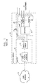
- Fig. 1 is a block diagram that schematically illustrates a DSLAM system 20 implementing a multi-shelf architecture, as is known in the art.
- System 20 comprises a master unit 25 coupled to multiple slave units 27 in a star configuration.
- Master unit 25 communicates with a core network 22, such as an ATM network.
- the master unit comprises a core network interface element 24, providing the necessary physical layer (PHY) and data link layer (for example, ATM) functions.
- a concentrator 26 performs higher-level functions, including VPI/VCI translation for the ATM network, and multiplexes downstream and upstream packets, or cells, among slave units 27.
- Each slave unit typically comprises a switching core 29, coupled to a plurality of ports 28 serving respective subscriber premises via suitable DSL modems. In the physical implementation of system 20, each such slave unit occupies its own shelf in an electronics rack, and this is the reason for the use of the term "multi-shelf.”
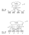
- Figs. 2A and 2B are block diagrams that schematically illustrate topologies known in the art for use in multi-shelf access systems, such as that shown in Fig. 1.
- Fig. 2A shows a simple star configuration.
- a redundant star configuration shown in Fig. 2B, each slave unit is connected to two or more alternative master units, so as to provide protection in case of a failure in one of the master units.
- a multi-shelf access system comprises two master units ("masters") and a plurality of slave units ("slaves").
- One of the masters serves as an active master, through which the slaves normally receive data packets from a core network and transmit packets back upstream to the network.
- the other master is termed a standby master.
- the slaves are connected in one or more daisy chains between the active and standby masters, and are configured so that both downstream and upstream packets can be transmitted in either direction along each of the chains, i.e., from or to either of the two masters.
- the upstream packets are bicast by the active master to both the core network and to the standby master.
- the standby master also transmits the upstream packets to the core network, in order to protect against faults in the network interface of the active master unit.
- each slave comprises a pre-switch, which examines each packet passed down its respective chain to determine whether the packet is destined for any of the ports on that slave.
- every packet passed between the masters and slaves has a pre-switch address. If the packet is addressed to a particular slave, the pre-switch on that slave conveys the packet to a switch or switching fabric of the slave, which routes the packet to the appropriate port. If the packet is a multicast packet with an appropriate pre-switch address, the pre-switch both conveys a copy of the packet to the switch or switching fabric of the slave and passes the packet on down the chain.
- the pre-switch similarly accepts packets carrying a "next" address, i.e., packets that are sent from one slave to its immediate neighbor for topology detection and diagnostics. Otherwise, the pre-switch rejects the packet and passes it on to the next slave along the chain.
- the pre-switch thus reduces the burden on the switching fabric of the slave and ensures that packets are passed down the chain at the full data rate supported by the master-slave interface. Furthermore, in the case of a fault in the slave, the pre-switch simply passes all packets through to the next slave in the chain, so that the effect of the fault is limited as far as possible.
- the slave pre-switch is bidirectional, i.e., it treats packets passed both up and down the chain in substantially the same manner.
- the pre-switch thus supports the failure protection mechanism described hereinabove, wherein the traffic direction is reversed in response to a failure in the chain.
- network access apparatus including:
- downstream data packets received from the network are passed from the first master unit to each of the daisy chains via the first slave unit in each chain, and upstream data packets received by the slaves in each chain from the subscriber lines are passed via the first slave unit in the chain to the first master unit for transmission over the network.
- the apparatus includes a protection interface, which couples the second master unit to the first master unit, and over which interface data packets are conveyed between the first and second master units in case of a fault.
- the first master unit bicasts the upstream data packets that it receives from the slave units to the network and, via the protection interface, to the second master unit, which transmits the upstream data packets to the network.
- the downstream data packets are passed from the second master unit to the slave units in the portion of the daisy chain via the last slave unit in the chain, and the upstream data packets are passed by the last slave unit to the second master unit.
- the downstream packets for the slave units in the portion of the daisy chain between the location of the fault and the second master unit are conveyed to the second master unit from the first master unit via another one of the daisy chains.
- each of the first and second master units includes:
- each of the slave units includes:
- each of the slave units is coupled to receive packets transferred thereto from the first and second master units over first and second ones of the physical interface lines, respectively, and the pre-switch passes the packets received through the first and second physical interface line and addressed to any of the ports on the slave unit to respective first and second addresses in the switch fabric.
- the first and second addresses are swapped in the pre-switch, so that substantially no reconfiguration of the switch fabric is required.
- the network includes an asynchronous transfer mode (ATM) network.
- the network includes an Internet protocol (IP) network.
- ATM asynchronous transfer mode
- IP Internet protocol
- a master unit - is connected by a physical interface to a packet-switched network
- a slave unit configured to be coupled to the master unit in a daisy chain of such slave units, the slave unit including:
- the pre-switch is further coupled to receive packets transferred thereto from the second physical interface and to sort the packets in like manner to the packets received through the first physical interface.
- the retained packets that were received from the first and second physical interfaces and are passed by the pre-switch to the switch fabric are identified by respective first and second port numbers, wherein in response to a reversal of a direction of data flow in the daisy chain, the first and second port numbers are swapped in the pre-switch, so that substantially no reconfiguration of the switch fabric is required in response to the reversal.
- the pre-switch sorts the multicast packet such that one copy of the packet is retained and another copy of the packet is passed to the second physical interface.
- the pre-switch continues to pass the packets addressed to the succeeding units on to the succeeding units without significant interruption.
- a method for providing access to a network including:
- the initial and further downstream packets are received from the network by the first master unit, and conveying the further downstream packets in the second direction includes conveying the further downstream packets from the first master unit to the second master unit, and then conveying the further downstream packets from the second master unit to the daisy chain.
- conveying the further downstream packets from the first master unit to the second master unit includes linking further slave units in an additional daisy chain between the first and second master units, and conveying the further downstream packets from the first master unit to the second master unit over the additional daisy chain.
- the method includes conveying initial upstream data packets, received by the slave units from the subscriber lines, along the daisy chain in the second direction so as to transmit the upstream data packets via the first master unit over the network, and in the event of the fault, conveying further upstream data packets received by one or more of the slave units along the daisy chain in the first direction via the second master unit.
- the method includes bicasting the upstream data packets from the first master unit to the network and to the second master unit, which transmits the bicast upstream data packets over the network.
- conveying the initial downstream data packets along the daisy chain includes pre-switching the packets at each of the slave units, so that packets not addressed to any of the ports on the slave unit are passed to the next slave unit in the daisy chain, while packets that are addressed to one or more of the ports on the slave unit are passed to a switch fabric that directs the packets to the ports to which they are addressed.
- Fig. 3 is a block diagram that schematically illustrates a multi-shelf access system 31, in accordance with a preferred embodiment of the present invention.
- System 31 is preferably a DSLAM, which provides subscriber access to an ATM network.
- system 31 may be configured for providing broadband access to substantially any high-speed, packet-switched network, such as an IP network, over substantially any suitable communications infrastructure.
- IP network such as an IP network
- System 31 comprises two mutually-linked masters 30 and 32, both of which are generally capable of performing the functions of master 25, including interfacing to network 22 and higher-level routing functions, as shown in Fig. 1 and described with reference thereto.
- a plurality of slaves 34 are connected between masters 30 and 32 by lines 38 in a number of daisy chains 36, 37 and 39.
- Each slave comprises multiple subscriber ports 28, which link system 31 to respective subscriber locations.
- three chains are shown in Fig. 2, each comprising four slaves 34, it will be appreciated that masters 30 and 32 may also be configured to accommodate greater or smaller numbers of chains and/or slaves.
- An advantage of the architecture of system 31 is that additional slaves may be added to the chains as needed, without having to change the number of interfaces associated with masters 30 and 32.
- Master 30 is termed the active master, because in normal operation of system 31, i.e., in the absence of faults in the system, downstream traffic from the network is routed from master 30 down chains 36, 37 and 39 to the respective slaves 34. Upstream traffic from the slaves is likewise routed up the chains to master 30. Active master 30 bicasts upstream packets to the network and to standby master 32. The standby master conveys copies of the upstream packets to the network, as well, as protection against a failure in the network interface of active master 30. In case of a fault in one of chains 36, 37 or 39, as described further hereinbelow, the traffic direction in all or a part of the faulty chain is reversed. Packets are then directed between some of the slaves and standby master 32, rather than directly between the slaves and active master 30. When a serious failure occurs in the active master, all traffic may be directed through the standby master.
- Fig. 4 is a block diagram that schematically illustrates details of one of slaves 34, showing particularly a pre-switch 60 in the slave, in accordance with a preferred embodiment of the present invention.
- This embodiment makes use of a pre-switch addressing scheme to facilitate traffic switching at the shelves.
- Every packet sent between masters 30 and 32 and slaves 34 has a pre-switch address (PSA), which identifies the packet as either:
- the PSA is implemented either by appending some extra bits to every packet, or by using part of an already existing packet header.
- the GFC portion of the standard ATM cell header is preferably used to accommodate the PSA.
- GFC is a four-bit field, of which three bits may be used for the PSA, and the remaining bit to indicate protection traffic.
- Using the GFC for the PSA limits the number of VPIs that can be allocated per slave shelf to 256. This limitation is most often acceptable, as it still allows at least one VPI per user. Alternatively, if more VPIs are required, extra bits may be appended to every cell.
- the "Next" (neighbor) address is used for various topology detection and diagnostic procedures.
- each shelf sends control packets with the "Next" address, carrying the identity of the sending shelf identity, as well as the identity of the neighbor as received over the link and, optionally, additional information.
- downstream data packets from active master 30 on line 38 are received by a first physical layer interface 40 and passed to a first demultiplexer 42 in pre-switch 60.
- the demultiplexer examines the PSA of the packets and, depending on this examination, takes the following actions:
- Upstream data packets are handled in an analogous fashion. Such packets are received by physical layer interface 52 and are passed to a second demultiplexer 54 in pre-switch 60. In this case, too, the pre-switch examines the packets to determine whether they carry a PSA corresponding to this slave 34. If so, another port number (PORT 1) of the slave is appended to the packet, identified by a block 58. In this case, the packets are passed to an input FIFO 56 and from there are conveyed to switching fabric 46 for routing to the appropriate port 28. Otherwise, the packets are sent to an output FIFO 62, for transmission upstream via physical layer interface 40.
- PORT 1 port number
- Packets that are received by slave 34 from ports 28 are passed by switch fabric 46 to output FIFO 62, as appropriate, for transmission back to active master 30. Alternatively, when a fault has occurred, the upstream packets from the ports are passed via FIFO 50 to standby master 32.
- pre-switch 60 is described herein in the context of system 31, it will be appreciated that the principles embodied in the pre-switch may similarly be applied, mutatis mutandis, in other multi-shelf access architectures.
- the pre-switching technique is particularly useful when slave shelves are daisy-chained together, even when the chain is not closed as it is in system 31.
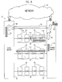
- Fig. 5 is a block diagram that schematically illustrates details of data packet flow in system 31 under normal, fault-free conditions, in accordance with a preferred embodiment of the present invention.
- Hatched arrows such as an arrow 72
- unfilled arrows such as an arrow 74
- Packets received from network 22 are routed by active master 30 down each of chains 36, 37 and 39, as indicated by arrow 72.
- Standby master 32 normally discards these downstream packets, as indicated by an arrow 80, except when a fault occurs in the active master.
- the active master bicasts these packets, sending them both to network 22 and to standby master 32 over a protection interface 76 between the two masters, as indicated by an arrow 77.
- the standby master also transmits the upstream packets over network 22, as indicated by an arrow 78.
- This redundancy in transmission is in accordance with fault protection mechanisms used in high-speed networks known in the art, such as the standard "1+1 APS" (automatic protection switching) technique used in SONET.
- Fig. 6 is a block diagram that schematically shows details of active master 30 in normal operation, in accordance with a preferred embodiment of the present invention.
- Master 30 comprises a main switch 90 and a pre-switch 92.
- the main switch receives downstream (incoming) packets from the network physical layer interface (NET PHY).
- the network interface has a switching address 102, corresponding to a switch port no. 5. (For the particular case of ATM switching, this and the other port numbers in the figure preferably correspond to UTOPIA addresses.)
- the packets are distributed to chains 36, 37 and 39 at respective addresses 98, 96 and 94 (switch ports 2, 1 and 0). Upstream packets are delivered to address 102 for transmission over the network.
- Pre-switch 92 bicasts these packets, as described hereinabove, to an address 100 (switch port 3) of protection interface 76 to standby master 32. Input packets to master 30 from the protection interface are discarded by pre-switch 92. Other than these protection functions, the pre-switch operates as a transparent pass-through, as shown in Fig. 6, as long as no faults have occurred in system 31.
- Fig. 7 is a block diagram that schematically shows details of standby master 32, in accordance with a preferred embodiment of the present invention.
- the standby master is structurally substantially identical to the active master, including main switch 90 and pre-switch 92.
- standby master 32 communicates only with active master 30, and is not expected to receive packets from or convey packets to any of slaves 34.
- Control traffic between the active and standby masters is preferably conveyed through chain 39, over an upstream path 104 and a downstream path 106 through the chain.
- Upstream data packets received by the standby master at address 100, over protection interface 76 from active master 30, are conveyed by pre-switch 92 to the network physical layer interface at address 102.
- the pre-switch passes any traffic from chains 36 and 37 transparently to switch 90, which treats any packets that it receives, except for control packets, as misrouted traffic.
- active master 30 and standby master 32 include their own local ports (not shown in the figures).
- the standby master is preferably treated as an additional slave on one of the chains, typically chain 39, and its ports have the same setup as all of the slave ports. Only the local ports of the active master have a different setup.
- the ports on the standby master are preferably assigned their own PSA, reducing by one the number of slaves that can be added on chain 39.
- Data traffic to and from the local ports on the standby master are carried over paths 106 and 104, in addition to the control traffic. Because protection interface 76 is reserved and, preferably, hardware-switched to deal with fault situations, it is undesirable to use this interface for the ordinary data and control traffic between the active and standby masters.
- Fig. 8 is a block diagram that schematically illustrates operation of system 31 in the event of a communication fault in chain 39, in accordance with a preferred embodiment of the present invention.
- the fault is indicated by a mark 110 between two of slaves 34 and 34' in the chain, between which communications have been interrupted.
- a fault would result in interruption of service to subscribers served by all of slaves 34' downstream of the fault.
- active master 30 recognizes that a fault has occurred, and commands standby master 32 and slaves 34 to take corrective action.
- Downstream traffic for slaves 34' is routed by active master 30 through chain 37, as indicated by an arrow 112.
- Standby master 32 switches this traffic onto chain 39, as shown by arrows 114 and 116, so that the packets reach slaves 34'.
- the addresses of the two inputs to the pre-switches 60 of slaves 34' are swapped, as described hereinabove (Fig. 4), in order to reverse the direction of traffic flow on this portion of chain 39.
- Upstream packets returned by slaves 34' are routed back to standby master 32, as shown by an arrow 118.
- the standby master switches this traffic over protection interface 76 to active master 30, as indicated by arrows 120 and 122. From this point, the upstream traffic is transmitted over network 22 in normal fashion. Traffic to and from slaves 34 on chains 36 and 37 is substantially unaffected. Failures in chains 36 and 37 are handled in similar fashion.
- Fig. 9 is a block diagram that schematically illustrates details of the operation of pre-switch 92 in active master 30 under the fault conditions shown in Fig. 8, in accordance with a preferred embodiment of the present invention.
- this block diagram and the other illustrations of pre-switch 92 show only the elements of the pre-switch that are of functional importance in handling this particular fault.
- the illustrated arrangement of these elements, and particularly of FIFO buffers in the pre-switch, has been chosen for simplicity and conceptual clarity, and variations on this arrangement will be apparent to those skilled in the art.
- a PSA router 130 in pre-switch 92 determines whether the packets are addressed to slaves 34, upstream of the fault indicated by mark 110, or slaves 34', downstream of the fault-.
- the PSA re-routes the traffic for slaves downstream of the fault through chain 37, in accordance with the following routing table: PSA address Original switch port New switch port 0 0 0 1 0 0 2 0 1 3 0 1 4 0 0 5 0 0 6 0 1
- PSA numbers 2 and 3 refer to slaves 34', whose traffic is thus routed via a FIFO 134 to address 96 (switch port 1) of chain 37.
- Broadcast traffic for chain 39 is routed by PSA router 130 to both chains 39 and 37, except for "Next" packets, which are sent only to chain 39.
- PSA router 130 preferably sets a bit reserved for this purpose in the packets destined for slaves 34'.
- router 130 preferably sets the least significant bit of the GFC field to 1. Standby master 32 changes this bit back to 0 when switching the packets back to chain 39.
- the traffic from slaves 34' over protection interface 76 is merged with the normal upstream traffic from slaves 34 on chain 39 by a FIFO 132.
- Switch 90 processes the merged traffic as though it had all come directly from chain 39, and no special processing is required after pre-switch 92.
- Fig. 10 is a block diagram that schematically illustrates details of pre-switch 92 in standby master 32 under the fault conditions of Figs. 8 and 9, in accordance with a preferred embodiment of the present invention.
- Downstream traffic from chain 37 is examined by a local filter 148 in pre-switch 92 of standby master 32.
- the filter identifies packets destined for slaves 34', preferably based on the least significant bit of the GFC field in the packets, as noted above, and routes these packets to address 94 (UTOPIA port 0) of chain 39.
- the local filter changes the least significant bits back to 0.
- Packets for local ports on the standby master are routed to a FIFO 144, from which they are conveyed to switch 90.
- Other packets, typically "next" traffic originating from the last slave 34 on chain 37 are passed by filter 148 directly to switch 90.
- next filter 142 which separates normal packet traffic from "Next" neighbor packets.
- the filter routes upstream packets, sent by slaves 34', to a FIFO 150. From this FIFO, these packets are conveyed through address 100, via protection interface 76, to active master 30. Upstream traffic from the local ports on the standby master is similarly routed by a next filter 140 to FIFO 150, and from there over the protection interface to the active master.
- the "Next" packets are routed by filters 140 and 142 directly between the standby master and chain 39.
- Figs. 8, 9 and 10 illustrate only a case in which a fault has occurred in chain 39, it will be understood that similar techniques may be applied when faults occur in chains 36 and 37. In fact, these latter cases are simpler to deal with, since control traffic between masters 30 and 32 is normally carried only over chain 39. In all cases, the use of pre-switches 92 in the two masters allows such faults to be handled substantially without any reprogramming or reconfiguration of switches 90.
Landscapes
- Engineering & Computer Science (AREA)
- Computer Networks & Wireless Communication (AREA)
- Signal Processing (AREA)
- Data Exchanges In Wide-Area Networks (AREA)
- Small-Scale Networks (AREA)
Abstract
Description
- The present invention relates generally to high-speed data communication systems, and specifically to digital subscriber line systems.
- Digital Subscriber Line (DSL) is a modem technology that enables broadband digital data to be transmitted over twisted-pair wire, which is the type of infrastructure that links most home and small business subscribers to their telephone service providers. DSL modems enable users to access digital networks at speeds tens to hundreds of times faster than current analog modems and basic ISDN service. DSL thus opens the most critical bottleneck in local-loop access to high-speed networks, such as Asynchronous Transfer Mode (ATM) and Internet Protocol (IP) networks, without requiring major investments in new infrastructure. A range of DSL standards have been defined, known generically as "xDSL," wherein the various standards have different data rates and other associated features but share common principles of operation.
- DSL subscribers are connected to high-speed networks through Digital Subscriber Line Access Multiplexer (DSLAM) systems. Because of the high cost of network bandwidth, a single DSLAM must typically be designed to serve between 100 and 1000 subscribers and to concentrate their traffic through one or a few network trunks. The need to serve such a large and potentially variable number of subscribers in the one DSLAM has led to the development of "multi-shelf" access architectures.
- Fig. 1 is a block diagram that schematically illustrates a
DSLAM system 20 implementing a multi-shelf architecture, as is known in the art.System 20 comprises amaster unit 25 coupled tomultiple slave units 27 in a star configuration.Master unit 25 communicates with acore network 22, such as an ATM network. The master unit comprises a corenetwork interface element 24, providing the necessary physical layer (PHY) and data link layer (for example, ATM) functions. Aconcentrator 26 performs higher-level functions, including VPI/VCI translation for the ATM network, and multiplexes downstream and upstream packets, or cells, amongslave units 27. Each slave unit typically comprises a switchingcore 29, coupled to a plurality ofports 28 serving respective subscriber premises via suitable DSL modems. In the physical implementation ofsystem 20, each such slave unit occupies its own shelf in an electronics rack, and this is the reason for the use of the term "multi-shelf." - Figs. 2A and 2B are block diagrams that schematically illustrate topologies known in the art for use in multi-shelf access systems, such as that shown in Fig. 1. Fig. 2A shows a simple star configuration. In a redundant star configuration, shown in Fig. 2B, each slave unit is connected to two or more alternative master units, so as to provide protection in case of a failure in one of the master units.
- It is an object of some aspects of the present invention to provide an improved multi-shelf access architecture.
- It is a further object of some aspects of the present invention to provide apparatus and methods for efficient, high-speed transfer of data packets within an access multiplexer system.
- It is still a further object of some aspects of the present invention to improve the robustness and reliability of multi-shelf access systems.
- In preferred embodiments of the present invention, a multi-shelf access system comprises two master units ("masters") and a plurality of slave units ("slaves"). One of the masters serves as an active master, through which the slaves normally receive data packets from a core network and transmit packets back upstream to the network. The other master is termed a standby master. The slaves are connected in one or more daisy chains between the active and standby masters, and are configured so that both downstream and upstream packets can be transmitted in either direction along each of the chains, i.e., from or to either of the two masters. Thus, if a failure occurs in any one of the slaves or in a link between them, the traffic direction in the chain in which the failure has occurred is simply reversed so as to run through the standby master. Substantially no reprogramming of the slaves is required for this purpose. All of the slaves (except possibly a slave that has failed) continue to provide service to subscribers, typically with only a short interruption until corrective action is completed.
- Preferably, the upstream packets are bicast by the active master to both the core network and to the standby master. The standby master also transmits the upstream packets to the core network, in order to protect against faults in the network interface of the active master unit.
- In some preferred embodiments of the present invention, each slave comprises a pre-switch, which examines each packet passed down its respective chain to determine whether the packet is destined for any of the ports on that slave. Preferably, every packet passed between the masters and slaves has a pre-switch address. If the packet is addressed to a particular slave, the pre-switch on that slave conveys the packet to a switch or switching fabric of the slave, which routes the packet to the appropriate port. If the packet is a multicast packet with an appropriate pre-switch address, the pre-switch both conveys a copy of the packet to the switch or switching fabric of the slave and passes the packet on down the chain. The pre-switch similarly accepts packets carrying a "next" address, i.e., packets that are sent from one slave to its immediate neighbor for topology detection and diagnostics. Otherwise, the pre-switch rejects the packet and passes it on to the next slave along the chain.
- The pre-switch thus reduces the burden on the switching fabric of the slave and ensures that packets are passed down the chain at the full data rate supported by the master-slave interface. Furthermore, in the case of a fault in the slave, the pre-switch simply passes all packets through to the next slave in the chain, so that the effect of the fault is limited as far as possible.
- Preferably, the slave pre-switch is bidirectional, i.e., it treats packets passed both up and down the chain in substantially the same manner. The pre-switch thus supports the failure protection mechanism described hereinabove, wherein the traffic direction is reversed in response to a failure in the chain.
- There is therefore provided, in accordance with a preferred embodiment of the present invention, network access apparatus, including:
- first and second master units, each including a physical interface to a packet-switched network;
- a plurality of slave units, each slave unit including one or more ports to respective subscriber lines; and
- a plurality of physical interface lines, which link the slave units in one or more daisy chains, in which the slave units are mutually connected in series by the physical interface lines therebetween, each daisy chain including at least a first slave unit connected by one of the physical interface lines to the first master unit and a last slave unit connected by another of the physical interface lines to the second master unit.
-
- Preferably, in normal operation, downstream data packets received from the network are passed from the first master unit to each of the daisy chains via the first slave unit in each chain, and upstream data packets received by the slaves in each chain from the subscriber lines are passed via the first slave unit in the chain to the first master unit for transmission over the network. Further preferably, the apparatus includes a protection interface, which couples the second master unit to the first master unit, and over which interface data packets are conveyed between the first and second master units in case of a fault. Most preferably, the first master unit bicasts the upstream data packets that it receives from the slave units to the network and, via the protection interface, to the second master unit, which transmits the upstream data packets to the network.
- Preferably, in case of a fault at a location in one of the daisy chains, data flow in a portion of the daisy chain between the location of the fault and the second master unit is reversed, so that the downstream data packets are passed from the second master unit to the slave units in the portion of the daisy chain via the last slave unit in the chain, and the upstream data packets are passed by the last slave unit to the second master unit. Further preferably, the downstream packets for the slave units in the portion of the daisy chain between the location of the fault and the second master unit are conveyed to the second master unit from the first master unit via another one of the daisy chains.
- In a preferred embodiment, each of the first and second master units includes:
- a switch, configured to route data packets between the respective physical interface and the one or more daisy chains; and
- a pre-switch, which in the event of a fault at a location in one of the daisy chains, re-routes at least a portion of the data packets exchanged with one or more of the slaves in the daisy chain in which the fault has occurred through another one of the daisy chains. Preferably, the pre-switch re-routes the data packets such -that substantially no reconfiguration of the switch is required responsive to the fault.
-
- In a further preferred embodiment, each of the slave units includes:
- a switch fabric including one or more switches, which convey data packets to respective ports on the switch to which the packets are addressed; and
- a pre-switch, which receives the data packets from one of the physical interface lines connected to the slave unit and passes those of the data packets that are addressed to any of the ports on the slave unit to the switch fabric, while passing packets not addressed to any of the ports on the slave unit for output through another of the physical interface lines.
-
- Preferably, each of the slave units is coupled to receive packets transferred thereto from the first and second master units over first and second ones of the physical interface lines, respectively, and the pre-switch passes the packets received through the first and second physical interface line and addressed to any of the ports on the slave unit to respective first and second addresses in the switch fabric. Further preferably, in response to a reversal of a direction of data flow in the daisy chain, the first and second addresses are swapped in the pre-switch, so that substantially no reconfiguration of the switch fabric is required.
- In a preferred embodiment, the network includes an asynchronous transfer mode (ATM) network. In another preferred embodiment, the network includes an Internet protocol (IP) network.
- There is further provided, in accordance with a preferred embodiment of the present invention, in a network access multiplexing system, in which a master unit - is connected by a physical interface to a packet-switched network, a slave unit configured to be coupled to the master unit in a daisy chain of such slave units, the slave unit including:
- a plurality of ports, for coupling the slave unit to respective subscriber lines;
- first and second physical interfaces, coupled to exchange packets with preceding and succeeding units, respectively, along the daisy chain;
- a pre-switch, coupled to receive packets from the first physical interface and responsive to address data carried by the packets, to sort the packets such that packets addressed to the slave unit are retained, and packets addressed to the succeeding units are passed to the second physical interface; and
- a fabric of one or more switches, which convey the retained packets to the ports, responsive to the address data.
-
- Preferably, the pre-switch is further coupled to receive packets transferred thereto from the second physical interface and to sort the packets in like manner to the packets received through the first physical interface. Most preferably, the retained packets that were received from the first and second physical interfaces and are passed by the pre-switch to the switch fabric are identified by respective first and second port numbers, wherein in response to a reversal of a direction of data flow in the daisy chain, the first and second port numbers are swapped in the pre-switch, so that substantially no reconfiguration of the switch fabric is required in response to the reversal.
- Further preferably, when one of the packets received by the pre-switch includes a multicast packet addressed to one or more of the ports on the slave unit, the pre-switch sorts the multicast packet such that one copy of the packet is retained and another copy of the packet is passed to the second physical interface.
- Preferably, in the event of a fault in the switch fabric, the pre-switch continues to pass the packets addressed to the succeeding units on to the succeeding units without significant interruption.
- There is also provided, in accordance with a preferred embodiment of the present invention, a method for providing access to a network, including:
- coupling first and second master units to interface with the network;
- linking a plurality of slave units, each slave unit including one or more ports to respective subscriber lines, in a daisy chain between the first and second master units;
- conveying initial downstream data packets, received from the network by one of the master units, along the daisy chain in a first direction, so as to deliver the packets to the ports of the slave units; and
- in the event of a fault in the daisy chain, conveying further downstream data packets, received from the network by one of the master units, along the daisy chain in a second direction, opposite to the first direction, so as to deliver the further packets to the ports of at least some of the slave units.
-
- Preferably, the initial and further downstream packets are received from the network by the first master unit, and conveying the further downstream packets in the second direction includes conveying the further downstream packets from the first master unit to the second master unit, and then conveying the further downstream packets from the second master unit to the daisy chain. Most preferably, conveying the further downstream packets from the first master unit to the second master unit includes linking further slave units in an additional daisy chain between the first and second master units, and conveying the further downstream packets from the first master unit to the second master unit over the additional daisy chain.
- Further preferably, the method includes conveying initial upstream data packets, received by the slave units from the subscriber lines, along the daisy chain in the second direction so as to transmit the upstream data packets via the first master unit over the network, and in the event of the fault, conveying further upstream data packets received by one or more of the slave units along the daisy chain in the first direction via the second master unit. Most preferably, the method includes bicasting the upstream data packets from the first master unit to the network and to the second master unit, which transmits the bicast upstream data packets over the network.
- Preferably, conveying the initial downstream data packets along the daisy chain includes pre-switching the packets at each of the slave units, so that packets not addressed to any of the ports on the slave unit are passed to the next slave unit in the daisy chain, while packets that are addressed to one or more of the ports on the slave unit are passed to a switch fabric that directs the packets to the ports to which they are addressed.
- The present invention will be more fully understood from the following detailed description of the preferred embodiments thereof, taken together with the drawings in which:
-
- Fig. 1 is a block diagram that schematically illustrates a multi-shelf access system, as is known in the art;
- Figs. 2A and 2B are block diagrams that schematically illustrate multi-shelf system topologies that are known in the art;
- Fig. 3 is a block diagram that schematically illustrates the topology of a multi-shelf access system, in accordance with a preferred embodiment of the present invention;
- Fig. 4 is a block diagram that schematically illustrates a pre-switch used in a slave unit of a multi-shelf access system, in accordance with a preferred embodiment of the present invention;
- Fig. 5 is a block diagram that schematically illustrates data flow in a multi-shelf access system under normal operating conditions, in accordance with a preferred embodiment of the present invention;
- Fig. 6 is a block diagram that schematically illustrates details of an active master in the system of Fig. 5, in accordance with a preferred embodiment of the present invention;
- Fig. 7 is a block diagram that schematically illustrates details of a standby master in the system of Fig. 5, in accordance with a preferred embodiment of the present invention;
- Fig. 8 is a block diagram that schematically illustrates data flow in the system of Fig. 5 under fault conditions, in accordance with a preferred embodiment of the present invention;
- Fig. 9 is a block diagram that schematically illustrates details of the active master in the system of Fig. - 5 under the fault conditions of Fig. 8, in accordance with a preferred embodiment of the present invention; and
- Fig. 10 is a block diagram that schematically illustrates details of the standby master in the system of Fig. 5 under the fault conditions of Fig. 8, in accordance with a preferred embodiment of the present invention.
-
- Fig. 3 is a block diagram that schematically illustrates a
multi-shelf access system 31, in accordance with a preferred embodiment of the present invention.System 31 is preferably a DSLAM, which provides subscriber access to an ATM network. Alternatively,system 31 may be configured for providing broadband access to substantially any high-speed, packet-switched network, such as an IP network, over substantially any suitable communications infrastructure. Some of the principles embodied in this system may also be applied in core network switching devices. -
System 31 comprises two mutually-linkedmasters master 25, including interfacing to network 22 and higher-level routing functions, as shown in Fig. 1 and described with reference thereto. A plurality ofslaves 34 are connected betweenmasters lines 38 in a number ofdaisy chains multiple subscriber ports 28, which linksystem 31 to respective subscriber locations. Although three chains are shown in Fig. 2, each comprising fourslaves 34, it will be appreciated thatmasters system 31 is that additional slaves may be added to the chains as needed, without having to change the number of interfaces associated withmasters -
Master 30 is termed the active master, because in normal operation ofsystem 31, i.e., in the absence of faults in the system, downstream traffic from the network is routed frommaster 30 downchains respective slaves 34. Upstream traffic from the slaves is likewise routed up the chains tomaster 30.Active master 30 bicasts upstream packets to the network and tostandby master 32. The standby master conveys copies of the upstream packets to the network, as well, as protection against a failure in the network interface ofactive master 30. In case of a fault in one ofchains standby master 32, rather than directly between the slaves andactive master 30. When a serious failure occurs in the active master, all traffic may be directed through the standby master. - Fig. 4 is a block diagram that schematically illustrates details of one of
slaves 34, showing particularly a pre-switch 60 in the slave, in accordance with a preferred embodiment of the present invention. This embodiment makes use of a pre-switch addressing scheme to facilitate traffic switching at the shelves. Every packet sent betweenmasters slaves 34 has a pre-switch address (PSA), which identifies the packet as either: - 1. A packet to/from a distinct slave shelf;
- 2. A broadcast/multicast packet; or
- 3. A- packet for immediate neighbor (also called "Next" address, because it addresses the next element along a chain). Pre-switch 60 processes packets according to their respective PSAs, as described further hereinbelow.
-
- A PSA need not be unique over the
entire multi-shelf system 31. Uniqueness is required, however, within anysingle chain - The PSA is implemented either by appending some extra bits to every packet, or by using part of an already existing packet header. Specifically, for ATM implementation, the GFC portion of the standard ATM cell header is preferably used to accommodate the PSA. GFC is a four-bit field, of which three bits may be used for the PSA, and the remaining bit to indicate protection traffic. Using the GFC for the PSA limits the number of VPIs that can be allocated per slave shelf to 256. This limitation is most often acceptable, as it still allows at least one VPI per user. Alternatively, if more VPIs are required, extra bits may be appended to every cell.
- The "Next" (neighbor) address is used for various topology detection and diagnostic procedures. Typically, each shelf sends control packets with the "Next" address, carrying the identity of the sending shelf identity, as well as the identity of the neighbor as received over the link and, optionally, additional information.
- Referring back to Fig. 4, downstream data packets from
active master 30 online 38 are received by a firstphysical layer interface 40 and passed to afirst demultiplexer 42 inpre-switch 60. The demultiplexer examines the PSA of the packets and, depending on this examination, takes the following actions: - If the PSA corresponds to this
slave 34, a port number (PORT 0) is appended to the packet. This port is identified schematically in Fig. 4 by ablock 48 in a switch or switchingfabric 46 of the slave. A demultiplexer 42 passes the packet to aninput FIFO 44, from which it is conveyed to switchingfabric 46, which then routes the packet to theappropriate port 28. - If the packet is a broadcast packet, sent to
slave 34, as well as to other slaves, the demultiplexer passes a copy of the packet, with the appropriate port number, to inputFIFO 44, and switchingfabric 46 routes the packet to the appropriate port, as described above. Another copy of the packet is passed to anoutput FIFO 50, from which it is sent through a secondphysical layer interface 52 overline 38 to the next slave in the chain. - If the PSA does correspond to this
slave 34,demultiplexer 42 passes the packet tooutput FIFO 50 and from there throughinterface 52 andline 38 to the next slave in the chain. - If the packet carries a "Next" neighbor address,
the demultiplexer passes the packet to input
FIFO 44 and from there to switchingfabric 46. - Upstream data packets are handled in an analogous fashion. Such packets are received by
physical layer interface 52 and are passed to asecond demultiplexer 54 inpre-switch 60. In this case, too, the pre-switch examines the packets to determine whether they carry a PSA corresponding to thisslave 34. If so, another port number (PORT 1) of the slave is appended to the packet, identified by ablock 58. In this case, the packets are passed to aninput FIFO 56 and from there are conveyed to switchingfabric 46 for routing to theappropriate port 28. Otherwise, the packets are sent to anoutput FIFO 62, for transmission upstream viaphysical layer interface 40. - Packets that are received by
slave 34 fromports 28 are passed byswitch fabric 46 tooutput FIFO 62, as appropriate, for transmission back toactive master 30. Alternatively, when a fault has occurred, the upstream packets from the ports are passed viaFIFO 50 tostandby master 32. - Because of the essential symmetry of
slave 34 and particularly ofpre-switch 60, the reversal in the direction of data flow overline 38 is accomplished without reprogramming look-up tables in switchingfabric 46. It is necessary only to swapports 0 and 1. The swap affects packets both received and transmitted by the slave, but it has no effect on through traffic, which is passed bydemultiplexers respective output FIFOs switch fabric 46 or elsewhere inslave 34, so that the slave is unable to transfer packets to or from itsports 28, pre-switch 60 simply passes all packets through to the next slaves (or master) up and down the chain. The effect of the fault is thus limited to the subscribers served by the particular slave, and other subscribers served bysystem 31 are substantially unaffected. - Although the operation of pre-switch 60 is described herein in the context of
system 31, it will be appreciated that the principles embodied in the pre-switch may similarly be applied, mutatis mutandis, in other multi-shelf access architectures. The pre-switching technique is particularly useful when slave shelves are daisy-chained together, even when the chain is not closed as it is insystem 31. - Fig. 5 is a block diagram that schematically illustrates details of data packet flow in
system 31 under normal, fault-free conditions, in accordance with a preferred embodiment of the present invention. Hatched arrows, such as anarrow 72, represent downstream data flow, while unfilled arrows, such as anarrow 74, represent upstream data flow. Packets received fromnetwork 22 are routed byactive master 30 down each ofchains arrow 72.Standby master 32 normally discards these downstream packets, as indicated by anarrow 80, except when a fault occurs in the active master. - Upstream packets, received by
slaves 34 from their respective ports, are passed up the respective chains toactive master 30. The active master bicasts these packets, sending them both tonetwork 22 and tostandby master 32 over aprotection interface 76 between the two masters, as indicated by anarrow 77. The standby master also transmits the upstream packets overnetwork 22, as indicated by anarrow 78. This redundancy in transmission is in accordance with fault protection mechanisms used in high-speed networks known in the art, such as the standard "1+1 APS" (automatic protection switching) technique used in SONET. - Fig. 6 is a block diagram that schematically shows details of
active master 30 in normal operation, in accordance with a preferred embodiment of the present invention.Master 30 comprises amain switch 90 and a pre-switch 92. The main switch receives downstream (incoming) packets from the network physical layer interface (NET PHY). The network interface has aswitching address 102, corresponding to a switch port no. 5. (For the particular case of ATM switching, this and the other port numbers in the figure preferably correspond to UTOPIA addresses.) The packets are distributed tochains respective addresses ports protection interface 76 tostandby master 32. Input packets to master 30 from the protection interface are discarded bypre-switch 92. Other than these protection functions, the pre-switch operates as a transparent pass-through, as shown in Fig. 6, as long as no faults have occurred insystem 31. - Fig. 7 is a block diagram that schematically shows details of
standby master 32, in accordance with a preferred embodiment of the present invention. The standby master is structurally substantially identical to the active master, includingmain switch 90 andpre-switch 92. In normal operation, as shown in the figure,standby master 32 communicates only withactive master 30, and is not expected to receive packets from or convey packets to any ofslaves 34. Control traffic between the active and standby masters is preferably conveyed throughchain 39, over anupstream path 104 and adownstream path 106 through the chain. Upstream data packets received by the standby master ataddress 100, overprotection interface 76 fromactive master 30, are conveyed by pre-switch 92 to the network physical layer interface ataddress 102. The pre-switch passes any traffic fromchains - Optionally,
active master 30 andstandby master 32 include their own local ports (not shown in the figures). In this case, the standby master is preferably treated as an additional slave on one of the chains, typically chain 39, and its ports have the same setup as all of the slave ports. Only the local ports of the active master have a different setup. The ports on the standby master are preferably assigned their own PSA, reducing by one the number of slaves that can be added onchain 39. Data traffic to and from the local ports on the standby master are carried overpaths protection interface 76 is reserved and, preferably, hardware-switched to deal with fault situations, it is undesirable to use this interface for the ordinary data and control traffic between the active and standby masters. - Fig. 8 is a block diagram that schematically illustrates operation of
system 31 in the event of a communication fault inchain 39, in accordance with a preferred embodiment of the present invention. The fault is indicated by amark 110 between two ofslaves 34 and 34' in the chain, between which communications have been interrupted. In multi-shelf topologies known in the art, such as those shown in Figs. 2A-2C, such a fault would result in interruption of service to subscribers served by all of slaves 34' downstream of the fault. Insystem 31, however,active master 30 recognizes that a fault has occurred, and commandsstandby master 32 andslaves 34 to take corrective action. - Downstream traffic for slaves 34' is routed by
active master 30 throughchain 37, as indicated by anarrow 112.Standby master 32 switches this traffic ontochain 39, as shown byarrows pre-switches 60 of slaves 34' are swapped, as described hereinabove (Fig. 4), in order to reverse the direction of traffic flow on this portion ofchain 39. Upstream packets returned by slaves 34' are routed back tostandby master 32, as shown by anarrow 118. The standby master switches this traffic overprotection interface 76 toactive master 30, as indicated byarrows network 22 in normal fashion. Traffic to and fromslaves 34 onchains chains - Fig. 9 is a block diagram that schematically illustrates details of the operation of pre-switch 92 in
active master 30 under the fault conditions shown in Fig. 8, in accordance with a preferred embodiment of the present invention. For clarity of illustration, this block diagram and the other illustrations of pre-switch 92 show only the elements of the pre-switch that are of functional importance in handling this particular fault. The illustrated arrangement of these elements, and particularly of FIFO buffers in the pre-switch, has been chosen for simplicity and conceptual clarity, and variations on this arrangement will be apparent to those skilled in the art. - For all incoming traffic destined for
chain 39, aPSA router 130 in pre-switch 92 determines whether the packets are addressed toslaves 34, upstream of the fault indicated bymark 110, or slaves 34', downstream of the fault-. The PSA re-routes the traffic for slaves downstream of the fault throughchain 37, in accordance with the following routing table:PSA address Original switch port New switch port 0 0 0 1 0 0 2 0 1 3 0 1 4 0 0 5 0 0 6 0 1 PSA numbers FIFO 134 to address 96 (switch port 1) ofchain 37. Broadcast traffic forchain 39 is routed byPSA router 130 to bothchains chain 39. - As noted hereinabove, it is necessary to avoid confusion between downstream traffic to slaves 34', transferred on
chain 37 as represented byarrow 112, and ordinary downstream traffic toslaves 34 located onchain 37 itself. For this reason,PSA router 130 preferably sets a bit reserved for this purpose in the packets destined for slaves 34'. In the case of ATM cells, for example,router 130 preferably sets the least significant bit of the GFC field to 1.Standby master 32 changes this bit back to 0 when switching the packets back tochain 39. - In the upstream direction, the traffic from slaves 34' over
protection interface 76, represented byarrow 122, is merged with the normal upstream traffic fromslaves 34 onchain 39 by aFIFO 132.Switch 90 processes the merged traffic as though it had all come directly fromchain 39, and no special processing is required afterpre-switch 92. - Fig. 10 is a block diagram that schematically illustrates details of pre-switch 92 in
standby master 32 under the fault conditions of Figs. 8 and 9, in accordance with a preferred embodiment of the present invention. Downstream traffic fromchain 37 is examined by alocal filter 148 inpre-switch 92 ofstandby master 32. The filter identifies packets destined for slaves 34', preferably based on the least significant bit of the GFC field in the packets, as noted above, and routes these packets to address 94 (UTOPIA port 0) ofchain 39. The local filter changes the least significant bits back to 0. Packets for local ports on the standby master are routed to aFIFO 144, from which they are conveyed to switch 90. Other packets, typically "next" traffic originating from thelast slave 34 onchain 37, are passed byfilter 148 directly to switch 90. - Traffic arriving at
standby master 32 fromchain 39 is received by anext filter 142, which separates normal packet traffic from "Next" neighbor packets. The filter routes upstream packets, sent by slaves 34', to aFIFO 150. From this FIFO, these packets are conveyed throughaddress 100, viaprotection interface 76, toactive master 30. Upstream traffic from the local ports on the standby master is similarly routed by anext filter 140 toFIFO 150, and from there over the protection interface to the active master. The "Next" packets, however, are routed byfilters chain 39. - While Figs. 8, 9 and 10 illustrate only a case in which a fault has occurred in
chain 39, it will be understood that similar techniques may be applied when faults occur inchains masters chain 39. In all cases, the use ofpre-switches 92 in the two masters allows such faults to be handled substantially without any reprogramming or reconfiguration ofswitches 90. - Although preferred embodiments are described hereinabove with reference to DSL access to an ATM network, the principles of the present invention are similarly applicable in providing access to substantially any type of packet-switched network, and over substantially any sort of subscriber interface. The architecture and switching techniques used in
system 31 are most advantageous when there is a need for high concentration at the access stage, i.e., for multiplexing of many lines into one or a few trunks. Those skilled in the art, however, will understand that the principles embodied insystem 31 may also be applied to multiplexers and switches of other types, even including core network devices. - It will thus be appreciated that the preferred embodiments described above are cited by way of example, and that the present invention is not limited to what has been particularly shown and described hereinabove. Rather, the scope of the present invention includes both combinations and subcombinations of the various features described hereinabove, as well as variations and modifications thereof which would occur to persons skilled in the art upon reading the foregoing description and which are not disclosed in the prior art.
Claims (26)
- Network access apparatus (31), comprising:characterized in that the slave units are mutually connected in series by the physical interface lines therebetween, each daisy chain comprising at least a first slave unit connected by one of the physical interface lines to the first master unit and a last slave unit connected by another of the physical interface lines to the second master unit.first and second master units (30,32), each comprising a physical interface to a packet-switched network;a plurality of slave units (34), each slave unit comprising one or more ports (28) to respective subscriber lines; anda plurality of physical interface lines (38), which link the slave units in one or more daisy chains (36, 37, 39),
- Apparatus according to claim 1, wherein in normal operation, downstream data packets received from the network are passed from the first master unit to each of the daisy chains via the first slave unit in each chain, and upstream data packets received by the slaves in each chain from the subscriber lines are passed via the first slave unit in the chain to the first master unit for transmission over the network.
- Apparatus according to claim 2, and comprising a protection interface, which couples the second master unit to the first master unit, and over which interface data packets are conveyed between the first and second master units in case of a fault.
- Apparatus according to claim 3, wherein the first master unit bicasts the upstream data packets that it receives from the slave units to the network and, via the protection interface, to the second master unit, which transmits the upstream data packets to the network.
- Apparatus according to any of claims 2-4, wherein in case of a fault at a location in one of the daisy chains, data flow in a portion of the daisy chain between the location of the fault and the second master unit is reversed, so that the downstream data packets are passed from the second master unit to the slave units in the portion of the daisy chain via the last slave unit in the chain, and the upstream data packets are passed by the last slave unit to the second master unit.
- Apparatus according to claim 5, wherein the downstream packets for the slave units in the portion of the daisy chain between the location of the fault and the second master unit are conveyed to the second master unit from the first master unit via another one of the daisy chains.
- Apparatus according to any of the preceding claims, wherein each of the first and second master units comprises:a switch, configured to route data packets between the respective physical interface and the one or more daisy chains; anda pre-switch, which in the event of a fault at a location in one of the daisy chains, re-routes at least a portion of the data packets exchanged with one or more of the slaves in the daisy chain in which the fault has occurred through another one of the daisy chains.
- Apparatus according to claim 7, wherein the pre-switch re-routes the data packets such that substantially no reconfiguration of the switch is required responsive to the fault.
- Apparatus according to any of the preceding claims, wherein each of the slave units comprises.:a switch fabric comprising one or more switches, which convey data packets to respective ports on the switch to which the packets are addressed; anda pre-switch, which receives the data packets from one of the physical interface lines connected to the slave unit and passes those of the data packets that are addressed to any of the ports on the slave unit to the switch fabric, while passing packets not addressed to any of the ports on the slave unit for output through another of the physical interface lines.
- Apparatus according to claim 9, wherein each of the slave units is coupled to receive packets transferred thereto from the first and second master units over first and second ones of the physical interface lines, respectively, and wherein the pre-switch passes the packets received through the first and second physical interface line and addressed to any of the ports on the slave unit to respective first and second addresses in the switch fabric.
- Apparatus according to claim 10, wherein in response to a reversal of a direction of data flow in the daisy chain, the first and second addresses are swapped in the pre-switch, so that substantially no reconfiguration of the switch fabric is required.
- Apparatus according to any of the preceding claims, wherein the network comprises an asynchronous transfer mode (ATM) network.
- Apparatus according to any of the preceding claims, wherein the network comprises an Internet protocol (IP) network.
- In a network access multiplexing system (31), in which a master unit (30,32) is connected by a physical interface to a packet-switched network, a slave unit (28) comprising a plurality of ports (28), for coupling the slave unit to respective subscriber lines, characterized in that the slave unit is configured to be coupled to the master unit in a daisy chain (36,37,39) of such slave units, and that the slave unit comprises:first and second physical interfaces (40,52), coupled to exchange packets with preceding and succeeding units, respectively, along the daisy chain;a pre-switch (60), coupled to receive packets from the first physical interface and responsive to address data carried by the packets, to sort the packets such that packets addressed to the slave unit are retained, and packets addressed to the succeeding units are passed to the second physical interface; anda fabric (46) of one or more switches, which convey the retained packets to the ports, responsive to the address data.
- Apparatus according to claim 14, wherein the pre-switch is further coupled to receive packets transferred thereto from the second physical interface and to sort the packets in like manner to the packets received through the first physical interface.
- Apparatus according to claim 15, wherein the retained packets that were received from the first and second physical interfaces and are passed by the pre-switch to the switch fabric are identified by respective first and second port numbers, and wherein in response to a reversal of a direction of data flow in the daisy chain, the first and second port numbers are swapped in the pre-switch, so that substantially no reconfiguration of the switch fabric is required in response to the reversal.
- Apparatus according to any of claims 14-16, wherein when one of the packets received by the pre-switch comprises a multicast packet addressed to one or more of the ports on the slave unit, the pre-switch sorts the multicast packet such that one copy of the packet is retained and another copy of the packet is passed to the second physical interface.
- Apparatus according to any of claims 14-17, wherein in the event of a fault in the switch fabric, the pre-switch continues to pass the packets addressed to the succeeding units on to the succeeding units without significant interruption.
- A method for providing access to a network, comprising:coupling first and second master units (30,32) to interface with the network;linking a plurality of slave units (34), each slave unit comprising one or more ports (28) to respective subscriber lines, in a daisy chain between the first and second master units;conveying initial downstream data packets, received from the network by one of the master units, along the daisy chain in a first direction, so as to deliver the packets to the ports of the slave units; andin the event of a fault in the daisy chain, conveying further downstream data packets, received from the network by one of the master units, along the daisy chain in a second direction, opposite to the first direction, so as to deliver the further packets to the ports of at least some of the slave units.
- A method according to claim 19, wherein the initial and further downstream packets are received from the network by the first master unit, and wherein conveying the further downstream packets in the second direction comprises conveying the further downstream packets from the first master unit to the second master unit, and then conveying the further downstream packets from the second master unit to the daisy chain.
- A method according to claim 20, wherein conveying the further downstream packets from the first master unit to the second master unit comprises linking further slave units in an additional daisy chain between the first and second master units, and conveying the further downstream packets from the first master unit to the second master unit over the additional daisy chain.
- A method according to any of claims 19-21, and comprising conveying initial upstream data packets, received by the slave units from the subscriber lines, along the daisy chain in the second direction so as to transmit the upstream data packets via the first master unit over the network, and in the event of the fault, conveying further upstream data packets received by one or more of the slave units along the daisy chain in the first direction via the second master unit.
- A method according to claim 22, and comprising bicasting the upstream data packets from the first master unit to the network and to the second master unit, which transmits the bicast upstream data packets over the network.
- A method according to any of claims 19-23, wherein conveying the initial downstream data packets along the daisy chain comprises pre-switching the packets at each of the slave units, so that packets not addressed to any of the ports on the slave unit are passed to the next slave unit in the daisy chain, while packets that are addressed to one or more of the ports on the slave unit are passed to a switch fabric that directs the packets to the ports to which they are addressed.
- A method according to any of claims 19-24, wherein the network comprises an asynchronous transfer mode (ATM) network.
- A method according to any of claims 19-25,- wherein the network comprises an Internet protocol (IP) network.
Applications Claiming Priority (2)
| Application Number | Priority Date | Filing Date | Title |
|---|---|---|---|
| US472683 | 1983-03-07 | ||
| US09/472,683 US6680904B1 (en) | 1999-12-27 | 1999-12-27 | Bi-directional chaining of network access ports |
Publications (1)
| Publication Number | Publication Date |
|---|---|
| EP1113697A2 true EP1113697A2 (en) | 2001-07-04 |
Family
ID=23876523
Family Applications (1)
| Application Number | Title | Priority Date | Filing Date |
|---|---|---|---|
| EP00308662A Withdrawn EP1113697A2 (en) | 1999-12-27 | 2000-10-02 | Bi-directional chaining of network access ports |
Country Status (2)
| Country | Link |
|---|---|
| US (1) | US6680904B1 (en) |
| EP (1) | EP1113697A2 (en) |
Cited By (3)
| Publication number | Priority date | Publication date | Assignee | Title |
|---|---|---|---|---|
| WO2003021999A1 (en) * | 2001-08-28 | 2003-03-13 | Sunrise Telecom Incorporated | Serial unit identification |
| JP2006518950A (en) * | 2003-01-16 | 2006-08-17 | ユーティースターコム・インコーポレーテッド | Method and apparatus for stacking digital subscriber line access multiplexer |
| WO2010151100A1 (en) * | 2009-06-26 | 2010-12-29 | Telekom Malaysia Berhad | Method and system for tagging packets routed to customer premises devices via clusters of dedicated customer interfaces |
Families Citing this family (99)
| Publication number | Priority date | Publication date | Assignee | Title |
|---|---|---|---|---|
| US7009977B1 (en) * | 2000-06-09 | 2006-03-07 | Conklin Corporation | Method and system for expanding services in a digital loop carrier system |
| US6894983B1 (en) | 2000-08-11 | 2005-05-17 | Orckit Communicatioins Ltd. | Automatic implementation of network configuration changes |
| US6834038B1 (en) * | 2000-08-11 | 2004-12-21 | Orckit Communications Ltd. | Protection against master unit failure in remote network access multiplexing |
| US6977922B2 (en) * | 2000-10-02 | 2005-12-20 | Paradyne Corporation | Systems and methods for automatically configuring cross-connections in a digital subscriber line access multiplexer (DSLAM) |
| US6822944B1 (en) * | 2000-11-08 | 2004-11-23 | Orckit Communications Ltd. | Management interface for a network access multiplexing system |
| US6822943B1 (en) * | 2000-11-08 | 2004-11-23 | Orckit Communications Ltd. | Network access multiplexer with protocol address translation |
| WO2003010869A1 (en) * | 2001-07-13 | 2003-02-06 | Shape Of Time, Inc. | System and method for providing network management |
| US7054264B2 (en) * | 2001-07-24 | 2006-05-30 | Corrigent Systems Ltd. | Interconnect and gateway protection in bidirectional ring networks |
| US6965558B1 (en) * | 2001-08-23 | 2005-11-15 | Cisco Technology, Inc. | Method and system for protecting a network interface |
| US7061859B2 (en) * | 2001-08-30 | 2006-06-13 | Corrigent Systems Ltd. | Fast protection in ring topologies |
| CA2357939A1 (en) * | 2001-09-27 | 2003-03-27 | Alcatel Canada Inc. | Master-slave communications system and method for a network element |
| US7072292B2 (en) * | 2001-11-13 | 2006-07-04 | Transwitch Corporation | Methods and apparatus for supporting multiple Utopia masters on the same Utopia bus |
| US7333426B1 (en) * | 2002-09-30 | 2008-02-19 | Nortel Networks Limited | Redundant inverse multiplexing over ATM (IMA) |
| US20050278503A1 (en) * | 2003-03-31 | 2005-12-15 | Mcdonnell Niall D | Coprocessor bus architecture |
| US7415011B2 (en) * | 2003-08-29 | 2008-08-19 | Sun Microsystems, Inc. | Distributed switch |
| US20060146810A1 (en) * | 2004-12-30 | 2006-07-06 | Thanh Bui | Multiple subscriber port architecture and methods of operation |
| US11948629B2 (en) | 2005-09-30 | 2024-04-02 | Mosaid Technologies Incorporated | Non-volatile memory device with concurrent bank operations |
| US20070165457A1 (en) * | 2005-09-30 | 2007-07-19 | Jin-Ki Kim | Nonvolatile memory system |
| US7652922B2 (en) | 2005-09-30 | 2010-01-26 | Mosaid Technologies Incorporated | Multiple independent serial link memory |
| US7747833B2 (en) | 2005-09-30 | 2010-06-29 | Mosaid Technologies Incorporated | Independent link and bank selection |
| TWI543185B (en) | 2005-09-30 | 2016-07-21 | 考文森智財管理公司 | Memory with output control and system thereof |
| US20070076502A1 (en) * | 2005-09-30 | 2007-04-05 | Pyeon Hong B | Daisy chain cascading devices |
| US8069328B2 (en) * | 2006-03-28 | 2011-11-29 | Mosaid Technologies Incorporated | Daisy chain cascade configuration recognition technique |
| US8335868B2 (en) * | 2006-03-28 | 2012-12-18 | Mosaid Technologies Incorporated | Apparatus and method for establishing device identifiers for serially interconnected devices |
| US8364861B2 (en) * | 2006-03-28 | 2013-01-29 | Mosaid Technologies Incorporated | Asynchronous ID generation |
| US7551492B2 (en) | 2006-03-29 | 2009-06-23 | Mosaid Technologies, Inc. | Non-volatile semiconductor memory with page erase |
| KR101194965B1 (en) * | 2006-03-31 | 2012-10-25 | 모사이드 테크놀로지스 인코퍼레이티드 | Flash memory system control method |
| US8407395B2 (en) | 2006-08-22 | 2013-03-26 | Mosaid Technologies Incorporated | Scalable memory system |
| US7904639B2 (en) * | 2006-08-22 | 2011-03-08 | Mosaid Technologies Incorporated | Modular command structure for memory and memory system |
| EP2487794A3 (en) * | 2006-08-22 | 2013-02-13 | Mosaid Technologies Incorporated | Modular command structure for memory and memory system |
| US8700818B2 (en) * | 2006-09-29 | 2014-04-15 | Mosaid Technologies Incorporated | Packet based ID generation for serially interconnected devices |
| US7817470B2 (en) | 2006-11-27 | 2010-10-19 | Mosaid Technologies Incorporated | Non-volatile memory serial core architecture |
| US8271758B2 (en) | 2006-12-06 | 2012-09-18 | Mosaid Technologies Incorporated | Apparatus and method for producing IDS for interconnected devices of mixed type |
| US7853727B2 (en) | 2006-12-06 | 2010-12-14 | Mosaid Technologies Incorporated | Apparatus and method for producing identifiers regardless of mixed device type in a serial interconnection |
| US8010709B2 (en) * | 2006-12-06 | 2011-08-30 | Mosaid Technologies Incorporated | Apparatus and method for producing device identifiers for serially interconnected devices of mixed type |
| US8331361B2 (en) | 2006-12-06 | 2012-12-11 | Mosaid Technologies Incorporated | Apparatus and method for producing device identifiers for serially interconnected devices of mixed type |
| US7818464B2 (en) * | 2006-12-06 | 2010-10-19 | Mosaid Technologies Incorporated | Apparatus and method for capturing serial input data |
| US7529149B2 (en) * | 2006-12-12 | 2009-05-05 | Mosaid Technologies Incorporated | Memory system and method with serial and parallel modes |
| US8984249B2 (en) * | 2006-12-20 | 2015-03-17 | Novachips Canada Inc. | ID generation apparatus and method for serially interconnected devices |
| US8010710B2 (en) | 2007-02-13 | 2011-08-30 | Mosaid Technologies Incorporated | Apparatus and method for identifying device type of serially interconnected devices |
| KR101494065B1 (en) * | 2007-02-16 | 2015-02-23 | 컨버전트 인텔렉츄얼 프로퍼티 매니지먼트 인코포레이티드 | Semiconductor device and method for reducing power consumption in a system having interconnected devices |
| US8122202B2 (en) * | 2007-02-16 | 2012-02-21 | Peter Gillingham | Reduced pin count interface |
| US7796462B2 (en) | 2007-02-22 | 2010-09-14 | Mosaid Technologies Incorporated | Data flow control in multiple independent port |
| US8086785B2 (en) | 2007-02-22 | 2011-12-27 | Mosaid Technologies Incorporated | System and method of page buffer operation for memory devices |
| US8046527B2 (en) | 2007-02-22 | 2011-10-25 | Mosaid Technologies Incorporated | Apparatus and method for using a page buffer of a memory device as a temporary cache |
| WO2009062280A1 (en) * | 2007-11-15 | 2009-05-22 | Mosaid Technologies Incorporated | Methods and systems for failure isolation and data recovery in a configuration of series-connected semiconductor devices |
| US7913128B2 (en) * | 2007-11-23 | 2011-03-22 | Mosaid Technologies Incorporated | Data channel test apparatus and method thereof |
| US8825939B2 (en) * | 2007-12-12 | 2014-09-02 | Conversant Intellectual Property Management Inc. | Semiconductor memory device suitable for interconnection in a ring topology |
| US7983099B2 (en) | 2007-12-20 | 2011-07-19 | Mosaid Technologies Incorporated | Dual function compatible non-volatile memory device |
| US7940572B2 (en) * | 2008-01-07 | 2011-05-10 | Mosaid Technologies Incorporated | NAND flash memory having multiple cell substrates |
| US8594110B2 (en) | 2008-01-11 | 2013-11-26 | Mosaid Technologies Incorporated | Ring-of-clusters network topologies |
| US8139390B2 (en) * | 2008-07-08 | 2012-03-20 | Mosaid Technologies Incorporated | Mixed data rates in memory devices and systems |
| US7957173B2 (en) * | 2008-10-14 | 2011-06-07 | Mosaid Technologies Incorporated | Composite memory having a bridging device for connecting discrete memory devices to a system |
| US8134852B2 (en) | 2008-10-14 | 2012-03-13 | Mosaid Technologies Incorporated | Bridge device architecture for connecting discrete memory devices to a system |
| US20100115172A1 (en) * | 2008-11-04 | 2010-05-06 | Mosaid Technologies Incorporated | Bridge device having a virtual page buffer |
| US8549209B2 (en) * | 2008-11-04 | 2013-10-01 | Mosaid Technologies Incorporated | Bridging device having a configurable virtual page size |
| US8194481B2 (en) * | 2008-12-18 | 2012-06-05 | Mosaid Technologies Incorporated | Semiconductor device with main memory unit and auxiliary memory unit requiring preset operation |
| US8037235B2 (en) * | 2008-12-18 | 2011-10-11 | Mosaid Technologies Incorporated | Device and method for transferring data to a non-volatile memory device |
| US8521980B2 (en) * | 2009-07-16 | 2013-08-27 | Mosaid Technologies Incorporated | Simultaneous read and write data transfer |
| US9274851B2 (en) * | 2009-11-25 | 2016-03-01 | Brocade Communications Systems, Inc. | Core-trunking across cores on physically separated processors allocated to a virtual machine based on configuration information including context information for virtual machines |
| US8195857B2 (en) * | 2009-12-18 | 2012-06-05 | Infineon Technologies Ag | Coupling devices, system comprising a coupling device and method for use in a system comprising a coupling device |
| US8238230B2 (en) * | 2010-02-03 | 2012-08-07 | Juniper Networks, Inc. | Detection of active nodes, safe node removal conditions, and cross-cabling conditions for maintenance operations within a multi-chassis routing matrix |
| US8576703B2 (en) * | 2010-03-19 | 2013-11-05 | Brocade Communications Systems, Inc. | Synchronization of multicast information using bicasting |
| US8769155B2 (en) * | 2010-03-19 | 2014-07-01 | Brocade Communications Systems, Inc. | Techniques for synchronizing application object instances |
| US8582382B2 (en) * | 2010-03-23 | 2013-11-12 | Mosaid Technologies Incorporated | Memory system having a plurality of serially connected devices |
| US9104619B2 (en) | 2010-07-23 | 2015-08-11 | Brocade Communications Systems, Inc. | Persisting data across warm boots |
| US8495418B2 (en) | 2010-07-23 | 2013-07-23 | Brocade Communications Systems, Inc. | Achieving ultra-high availability using a single CPU |
| US9143335B2 (en) | 2011-09-16 | 2015-09-22 | Brocade Communications Systems, Inc. | Multicast route cache system |
| US8825967B2 (en) | 2011-12-08 | 2014-09-02 | Conversant Intellectual Property Management Inc. | Independent write and read control in serially-connected devices |
| US9191203B2 (en) | 2013-08-06 | 2015-11-17 | Bedrock Automation Platforms Inc. | Secure industrial control system |
| US8971072B2 (en) | 2011-12-30 | 2015-03-03 | Bedrock Automation Platforms Inc. | Electromagnetic connector for an industrial control system |
| US9437967B2 (en) | 2011-12-30 | 2016-09-06 | Bedrock Automation Platforms, Inc. | Electromagnetic connector for an industrial control system |
| US11144630B2 (en) | 2011-12-30 | 2021-10-12 | Bedrock Automation Platforms Inc. | Image capture devices for a secure industrial control system |
| US9600434B1 (en) | 2011-12-30 | 2017-03-21 | Bedrock Automation Platforms, Inc. | Switch fabric having a serial communications interface and a parallel communications interface |
| US10834094B2 (en) | 2013-08-06 | 2020-11-10 | Bedrock Automation Platforms Inc. | Operator action authentication in an industrial control system |
| US9467297B2 (en) | 2013-08-06 | 2016-10-11 | Bedrock Automation Platforms Inc. | Industrial control system redundant communications/control modules authentication |
| US10834820B2 (en) | 2013-08-06 | 2020-11-10 | Bedrock Automation Platforms Inc. | Industrial control system cable |
| US8868813B2 (en) | 2011-12-30 | 2014-10-21 | Bedrock Automation Platforms Inc. | Communications control system with a serial communications interface and a parallel communications interface |
| US12061685B2 (en) | 2011-12-30 | 2024-08-13 | Analog Devices, Inc. | Image capture devices for a secure industrial control system |
| US11314854B2 (en) | 2011-12-30 | 2022-04-26 | Bedrock Automation Platforms Inc. | Image capture devices for a secure industrial control system |
| US9727511B2 (en) | 2011-12-30 | 2017-08-08 | Bedrock Automation Platforms Inc. | Input/output module with multi-channel switching capability |
| US8862802B2 (en) * | 2011-12-30 | 2014-10-14 | Bedrock Automation Platforms Inc. | Switch fabric having a serial communications interface and a parallel communications interface |
| US11967839B2 (en) | 2011-12-30 | 2024-04-23 | Analog Devices, Inc. | Electromagnetic connector for an industrial control system |
| US10581763B2 (en) | 2012-09-21 | 2020-03-03 | Avago Technologies International Sales Pte. Limited | High availability application messaging layer |
| US9967106B2 (en) | 2012-09-24 | 2018-05-08 | Brocade Communications Systems LLC | Role based multicast messaging infrastructure |
| US9203690B2 (en) | 2012-09-24 | 2015-12-01 | Brocade Communications Systems, Inc. | Role based multicast messaging infrastructure |
| US10613567B2 (en) | 2013-08-06 | 2020-04-07 | Bedrock Automation Platforms Inc. | Secure power supply for an industrial control system |
| CN105281061A (en) | 2014-07-07 | 2016-01-27 | 基岩自动化平台公司 | Industrial control system cable |
| US9619349B2 (en) | 2014-10-14 | 2017-04-11 | Brocade Communications Systems, Inc. | Biasing active-standby determination |
| CN105812500A (en) * | 2014-12-31 | 2016-07-27 | 鸿富锦精密工业(深圳)有限公司 | Electronic device group connection system and method |
| TWI612788B (en) * | 2015-12-21 | 2018-01-21 | 視動自動化科技股份有限公司 | Communication system with train bus architecture |
| CN107025191A (en) * | 2016-01-30 | 2017-08-08 | 鸿富锦精密电子(重庆)有限公司 | Electronic installation connects system |
| CN107025192A (en) * | 2016-01-30 | 2017-08-08 | 鸿富锦精密电子(重庆)有限公司 | Electronic installation connects system |
| CN106249585A (en) * | 2016-09-14 | 2016-12-21 | 国网辽宁省电力有限公司锦州供电公司 | The electric power payment active/standby changing method of machine based on string of binary characters |
| WO2020147933A1 (en) * | 2019-01-15 | 2020-07-23 | Heldeis Christoph | Keyboard, bus unit, bus control unit and method for operating a keyboard |
| CN117063135A (en) * | 2021-03-24 | 2023-11-14 | 发那科株式会社 | I/O unit, main unit and communication system |
| US12561263B2 (en) * | 2021-03-24 | 2026-02-24 | Fanuc Corporation | I/O unit |
| CN113852529B (en) * | 2021-08-11 | 2023-03-24 | 交控科技股份有限公司 | Back board bus system for data communication of trackside equipment and data transmission method thereof |
| CN117931718B (en) * | 2024-01-29 | 2025-02-11 | 合肥为国半导体有限公司 | A daisy chain structure and signal transmission method thereof |
Family Cites Families (8)
| Publication number | Priority date | Publication date | Assignee | Title |
|---|---|---|---|---|
| TW401670B (en) * | 1994-08-08 | 2000-08-11 | Symbios Logic Inc | Movie-on-demand disk storage loop architecture |
| AU6171598A (en) * | 1997-02-18 | 1998-09-08 | Cisco Technology, Inc. | Method and apparatus for multiplexing of multiple users on the same virtual circuit |
| US6215863B1 (en) * | 1997-12-29 | 2001-04-10 | Ameritech Corporation | Method and apparatus for providing a station set with advanced telecommunications services |
| US6317415B1 (en) * | 1998-09-28 | 2001-11-13 | Raytheon Company | Method and system for communicating information in a network |
| US6219354B1 (en) * | 1998-12-30 | 2001-04-17 | Qwest Communications International Inc. | VDSL cabinet designs and configurations |
| US6181715B1 (en) * | 1999-05-27 | 2001-01-30 | Qwest Communications International Inc. | Method and system for providing emulated telephony over DSL |
| US6404861B1 (en) * | 1999-10-25 | 2002-06-11 | E-Cell Technologies | DSL modem with management capability |
| US6424657B1 (en) * | 2000-08-10 | 2002-07-23 | Verizon Communications Inc. | Traffic queueing for remote terminal DSLAMs |
-
1999
- 1999-12-27 US US09/472,683 patent/US6680904B1/en not_active Expired - Lifetime
-
2000
- 2000-10-02 EP EP00308662A patent/EP1113697A2/en not_active Withdrawn
Cited By (6)
| Publication number | Priority date | Publication date | Assignee | Title |
|---|---|---|---|---|
| WO2003021999A1 (en) * | 2001-08-28 | 2003-03-13 | Sunrise Telecom Incorporated | Serial unit identification |
| US6775726B2 (en) | 2001-08-28 | 2004-08-10 | Sunrise Telecom Incorporated | Serial unit identification |
| JP2006518950A (en) * | 2003-01-16 | 2006-08-17 | ユーティースターコム・インコーポレーテッド | Method and apparatus for stacking digital subscriber line access multiplexer |
| EP1584150A4 (en) * | 2003-01-16 | 2006-10-18 | Utstarcom Inc | Method and apparatus for digital subscriber line access multiplexer stacking |
| WO2010151100A1 (en) * | 2009-06-26 | 2010-12-29 | Telekom Malaysia Berhad | Method and system for tagging packets routed to customer premises devices via clusters of dedicated customer interfaces |
| US8780915B2 (en) | 2009-06-26 | 2014-07-15 | Telekom Malaysia Berhad | Method and system for tagging packets routed to customer premises devices via clusters of dedicated customer interfaces |
Also Published As
| Publication number | Publication date |
|---|---|
| US6680904B1 (en) | 2004-01-20 |
Similar Documents
| Publication | Publication Date | Title |
|---|---|---|
| US6680904B1 (en) | Bi-directional chaining of network access ports | |
| US6611526B1 (en) | System having a meshed backplane and process for transferring data therethrough | |
| US6301254B1 (en) | Virtual path ring protection method and apparatus | |
| JP3667337B2 (en) | ATM exchange system | |
| EP0875123B1 (en) | Atm network with ring architecture | |
| US20030002505A1 (en) | Apparatus and method for packet-based switching | |
| US20030012196A1 (en) | Promiscuous network monitoring utilizing multicasting within a switch | |
| CA2074346C (en) | Telecommunication system | |
| EP0666004A1 (en) | A broadband virtual private network service and system | |
| US6834038B1 (en) | Protection against master unit failure in remote network access multiplexing | |
| US7477663B2 (en) | High layer bonding of multiple access lines for carrier grade access | |
| US6473397B1 (en) | Add/drop multiplexer and method, and Bi-directional line switcher ring featuring such multiplexers | |
| JPH0738565A (en) | ATM switch and its test method | |
| US7428208B2 (en) | Multi-service telecommunication switch | |
| US6396811B1 (en) | Segmented performance monitoring of multi-stage ATM node | |
| US5712854A (en) | Method of routing cells in an asynchronous time-division multiplex switching network and corresponding network input switch and application | |
| US6343077B1 (en) | Stackable UTOPIA switching apparatus for a broadband switching system | |
| US6822944B1 (en) | Management interface for a network access multiplexing system | |
| US7486612B2 (en) | Fault-tolerant multicasting network | |
| KR100306171B1 (en) | Method and apparatus to provide facility and module redundancy in telecommunication switching equipment | |
| US6778538B2 (en) | Virtual junctors | |
| CN1319967A (en) | Method and device for providing facilities and module redundancy in telecommunication exchange equipment | |
| EP0944288A2 (en) | An ATM exchange having packet processing trunks | |
| EP1476993B1 (en) | Port label switching | |
| EP1962544B1 (en) | An access node and method for reliable bonding of subscriber lines |
Legal Events
| Date | Code | Title | Description |
|---|---|---|---|
| PUAI | Public reference made under article 153(3) epc to a published international application that has entered the european phase |
Free format text: ORIGINAL CODE: 0009012 |
|
| AK | Designated contracting states |
Kind code of ref document: A2 Designated state(s): AT BE CH CY DE DK ES FI FR GB GR IE IT LI LU MC NL PT SE |
|
| AX | Request for extension of the european patent |
Free format text: AL;LT;LV;MK;RO;SI |
|
| RIN1 | Information on inventor provided before grant (corrected) |
Inventor name: KINAMON, ROY Inventor name: PANETH, ERIC Inventor name: MAGAL, ELI C/O ORCKIT COMMUNICATIONS LRD. Inventor name: ALONI, ELI Inventor name: SDAYOOR, RON Inventor name: KAPLAN, MENACHEM Inventor name: ZELIG, DAVID |
|
| STAA | Information on the status of an ep patent application or granted ep patent |
Free format text: STATUS: THE APPLICATION IS DEEMED TO BE WITHDRAWN |
|
| 18D | Application deemed to be withdrawn |
Effective date: 20030501 |