EP1584147B1 - Amplified optical ring transmission system - Google Patents
Amplified optical ring transmission system Download PDFInfo
- Publication number
- EP1584147B1 EP1584147B1 EP03796235A EP03796235A EP1584147B1 EP 1584147 B1 EP1584147 B1 EP 1584147B1 EP 03796235 A EP03796235 A EP 03796235A EP 03796235 A EP03796235 A EP 03796235A EP 1584147 B1 EP1584147 B1 EP 1584147B1
- Authority
- EP
- European Patent Office
- Prior art keywords
- gain
- ring
- peak
- amplifier
- ase
- Prior art date
- Legal status (The legal status is an assumption and is not a legal conclusion. Google has not performed a legal analysis and makes no representation as to the accuracy of the status listed.)
- Expired - Lifetime
Links
- 230000003287 optical effect Effects 0.000 title claims description 46
- 230000005540 biological transmission Effects 0.000 title claims description 11
- 238000000034 method Methods 0.000 claims description 14
- 239000000835 fiber Substances 0.000 claims description 13
- 230000006641 stabilisation Effects 0.000 claims description 10
- 238000011105 stabilization Methods 0.000 claims description 10
- 229910052761 rare earth metal Inorganic materials 0.000 claims description 9
- 150000002910 rare earth metals Chemical class 0.000 claims description 9
- 230000008859 change Effects 0.000 claims description 3
- 230000003595 spectral effect Effects 0.000 claims description 3
- 230000000694 effects Effects 0.000 description 8
- 238000004891 communication Methods 0.000 description 6
- 238000001228 spectrum Methods 0.000 description 5
- 239000013307 optical fiber Substances 0.000 description 4
- 230000003321 amplification Effects 0.000 description 3
- 238000003199 nucleic acid amplification method Methods 0.000 description 3
- 230000002269 spontaneous effect Effects 0.000 description 3
- 238000013459 approach Methods 0.000 description 2
- 230000004083 survival effect Effects 0.000 description 2
- 230000032683 aging Effects 0.000 description 1
- 230000000903 blocking effect Effects 0.000 description 1
- 238000013461 design Methods 0.000 description 1
- 238000010586 diagram Methods 0.000 description 1
- 230000003993 interaction Effects 0.000 description 1
- 230000007774 longterm Effects 0.000 description 1
- 239000000203 mixture Substances 0.000 description 1
- 238000012544 monitoring process Methods 0.000 description 1
- 230000001902 propagating effect Effects 0.000 description 1
- 238000005086 pumping Methods 0.000 description 1
- 230000009467 reduction Effects 0.000 description 1
- 230000000087 stabilizing effect Effects 0.000 description 1
Images
Classifications
-
- H—ELECTRICITY
- H04—ELECTRIC COMMUNICATION TECHNIQUE
- H04B—TRANSMISSION
- H04B10/00—Transmission systems employing electromagnetic waves other than radio-waves, e.g. infrared, visible or ultraviolet light, or employing corpuscular radiation, e.g. quantum communication
- H04B10/29—Repeaters
- H04B10/291—Repeaters in which processing or amplification is carried out without conversion of the main signal from optical form
-
- H—ELECTRICITY
- H04—ELECTRIC COMMUNICATION TECHNIQUE
- H04J—MULTIPLEX COMMUNICATION
- H04J14/00—Optical multiplex systems
- H04J14/02—Wavelength-division multiplex systems
- H04J14/0201—Add-and-drop multiplexing
-
- H—ELECTRICITY
- H04—ELECTRIC COMMUNICATION TECHNIQUE
- H04J—MULTIPLEX COMMUNICATION
- H04J14/00—Optical multiplex systems
- H04J14/02—Wavelength-division multiplex systems
- H04J14/0221—Power control, e.g. to keep the total optical power constant
-
- H—ELECTRICITY
- H04—ELECTRIC COMMUNICATION TECHNIQUE
- H04J—MULTIPLEX COMMUNICATION
- H04J14/00—Optical multiplex systems
- H04J14/02—Wavelength-division multiplex systems
- H04J14/0278—WDM optical network architectures
- H04J14/0283—WDM ring architectures
Definitions
- the present invention relates to an optical transmission ring where at least one optical amplifier is needed to compensate for losses in the fibers and in the passive components and in particular in a transmission system operating with Wavelength Division Multiplexing (WDM).
- WDM Wavelength Division Multiplexing
- ASEs amplified spontaneous emissions
- EDFA Erbium-Doped Fiber Amplifier
- WDM ring structures usually employ filters for adding or extracting specific channels from the optical line. In many cases to compensate for losses in the fibers or filters one or more optical amplifiers are necessary along the ring. The noise produced by these amplifiers outside the band allocated for the channels can recirculate in the ring if not controlled. If overall gain on the network ring is more than one, i.e. total gain is greater than total losses as may happen if some amplifier amplifies more than the attenuation of the preceding section, the ASE noise could be amplified as a signal and grow indiscriminately in the ring because of recirculation, making it difficult to control the ring status and ensure survival of the traffic channels.
- the first is to introduce an interruption along the ASE noise path at some point on the ring. In this manner the problem is solved with the disadvantage of having to introduce additional passive components and/or with the loss of flexibility in the system.
- Centralized traffic is necessary or any traffic reconfiguration requires the visit of the node which realizes the ASE interruption.
- the second approach tends to force the network ring gain to keep it below the lasing threshold so that the ASE recirculation cannot increase in power while propagating along the ring.
- a problem with this approach is that EDFA or similar amplifiers have gain which depends on the power applied at input and in the power grid the power input to the amplifiers depends in turn on the number of channels active at that time. For this reason, in order to keep total gain beneath the lasing threshold under all possible conditions, including the addition or removal of channels and nodes, a complex global control algorithm of the ring with many monitoring points is needed or else it is necessary to hold the gain of the individual amplifiers low enough to ensure that even under conditions leading to the highest gain of the amplifiers the total gain in the network is less than 1. But this solution involves a considerable reduction in the overall performance achievable since when far from the highest gain conditions amplification of the individual amplifiers is much lower that that which could be realized.
- US6, 175, 436 describes an apparatus and method for controlling the gain in an erbium-doped fiber amplifier incorporated into a multi-wavelength communication system so as to amplify each of the wavelength signals.
- the amplifier operates near to saturation so that, if one or more of the multi-wavelength signals is removed from the transmission, the remaining channels are increasingly amplified, leading to problems with other components in the system which depend upon intensity. Accordingly, an optical signal at a wavelength that is not within any of the transmission channels is selectively fed back around the amplifier and caused to lase in a wavelength-filtered ring-laser configuration.
- US6,421,168 describes a wavelength division multiplexed optical communications system including an optical fiber ring configured to carry at least one wavelength division multiplexed optical communication signal having plural optical channels at different wavelengths.
- Optical amplifiers are interposed along the optical fiber ring for optically amplifying the wavelength division multiplexed optical communication signal.
- Each optical amplifier produces amplified spontaneous emission as well as amplifying the optical channels of the WDM signal.
- amplified spontaneous emission is selected by an optical feedback selector and is fed back to the optical amplifier input via an optical feedback path; the created wavelength travels along the ring and is dropped near the input of the next adjacent amplifier, reducing ASE in the optical fiber ring.
- US6,421,168 describes that using this technique, closed-ring amplified WDM metropolitan networks can be formed without the need to "break the ring" in order to avoid uncontrolled build-up of ASE.
- optical transport rings have great advantages in that at any access point or node a channel traversing the node does not necessitate being regenerated as would be necessary with a point-to-point system closed in a ring.
- Optical rings are thus the most suitable transport structures in metropolitan or regional areas where a mixture of centralized and network services is required. For these applications it is essential to provide the most economical and simplest solution for amplifying the signal without introducing excessive costs and disadvantages.
- the present invention provides a way of doing this.
- the general purpose of the present invention is to remedy the above mentioned shortcomings by making available a control method and an WDM amplified optical ring system realized in accordance with the method which is capable of high performance, reliability, ease of realization and control and reduced costs.
- a gain control method in a ringed optical transmission system comprising along the ring rare earth doped fiber amplifiers and comprising positioning a gain peak at a wavelength ( ⁇ ASE ) outside the band ( ⁇ 1 - ⁇ n ) of the channels transmitted along the ring and corresponding to an ASE emission peak of the amplifiers in the ring and employing the lasing peak produced thus as a gain stabilization signal.
- a ringed optical transmission system comprising rare earth doped fiber amplifiers along the ring and characterized in that in them is a gain peak at a wavelength ( ⁇ ASE ) outside the band ( ⁇ 1 - ⁇ n ) of the channels along the ring and said wavelength corresponds to an ASE emission peak of the amplifiers in the ring so as to produce a lasing peak acting as a gain stabilization signal.
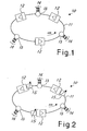
- FIG 1 shows diagrammatically a wavelength-division multiplexing (WDM) ring network designated as a whole by reference number 10 and applying the principles of the present invention.
- the ring comprises typically EDFA rare earth doped fiber amplifiers 12 connected in an optical fiber ring 11.
- the amplifiers are of a known type and not further discussed or shown as they are readily imaginable to those skilled in the art.
- nodes 13 At points in the network there are nodes 13 at which channels 14 are taken off or fed in. The number of channels taken off or fed in can vary from one node to the next and from one moment to the next in accordance with the specific needs of the network.
- an ASE noise produced by the amplifiers also circulate in the network.
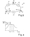
- FIG 4 shows diagrammatically the behavior of the gain spectrum of an EDFA or of an EDFA chain.
- the curve shown is merely explanatory and its exact behavior depends on many known factors which are not discussed here because they are not of interest in this specific case.
- the amplifiers employed are realized or, as clarified below, have devices such as input filters so that the gain spectrum will have a behavior as flat as desired in the ⁇ 1 - ⁇ n band of the channels and relatively high peak at the ⁇ ASE wavelength (outside the channel band) corresponding to an ASE emission peak. For an EDFA, this peak is around 1532nm.
- the gain on the ring (which has the same general behavior), at peak the gain will be unity (1) to avoid uncontrolled increase of the ASE signal.
- the system reaches this value as a condition of balance. It was found that the difference in gain ⁇ G between peak gain and channel band gain should preferably be greater than or equal to 1dB so that the peak will remain steady in the position selected far from the channels but not too far from 1dB value so that the channels will have sufficient amplification.
- the preferred optimal value for ⁇ G was therefore found to be around 1dB.
- Recirculation of the ASE noise is subject to peak gain effects which produce a peak lasing at ⁇ ASE (as stated, outside the band ⁇ 1 - ⁇ n reserved for the channels).
- This peak lasing usually considered harmful in known normal systems, can on the contrary be used as a signal for stabilizing the gain of all the amplifiers in the ring, hence achieving a ring with blocked gain with the stabilization signal which is not inside a particular individual amplifier but is common to all the amplifiers in the ring.
- EDFA amplifiers are preferably made to operate near saturation because under this condition the output power is virtually constant.
- the problem in general is that variation in the number of channels changes the input powers while shifting the work point of the amplifier.
- the present invention supplies an amplified WDM optical ring where stabilization of all the work points of the amplifiers following the addition or removal of channels and nodes is achieved by controlling the lasing effect on the ASE noise.
- all the amplifiers of the ring are controlled and stabilized by increase and control of the ASE noise lasing peak.
- the present invention takes into consideration an entire ring network instead of an individual amplifier.
- the ring closing can be considered realization of both an amplification circuit and a feedback circuit.
- the optical feedback signal can be represented by the same ASE noise generated by the lasing effect and which circulates in the ring.
- the entire network forms a controlled fiber ring laser.
- the lasing effect peak will be formed in a spectral position outside the band of the channels where the recirculation spectrum experiences the highest gain. It is thus possible to position the lasing effect noise peak at the desired wavelength ⁇ ASE outside the band of the signals thanks to the design and/or control of the EDFAs according to what is now readily imaginable to those skilled in the art,. It is also possible to use specific known gain flattering filters (GFF) to create the required overall gain profile in such a manner as to force the lasing peak to a certain wavelength, for example, far enough from the traffic channels to avoid nonlinear interactions.
- GFF gain flattering filters
- channels can be added to and/or removed from any node in the ring without causing any significant change in the total power input to the amplifiers and therefore to the amplifier gains while achieving channel power survival thereby.
- the peak lasing power will diminish, while when channels are removed it will rise.
- the addition or removal of one or more channels at a time has negligible effects on the remaining channels.
- a first variant comprises a variable optical attenuator 15 before each optical amplifier 12 for controlling its work point and hence its spectral gain profile when variations in the losses occur in the preceding section, for example, ageing of the transmission fibers, readjustments of the cables, additional junctions, etc.
- a variable optical attenuator 15 before each optical amplifier 12 for controlling its work point and hence its spectral gain profile when variations in the losses occur in the preceding section, for example, ageing of the transmission fibers, readjustments of the cables, additional junctions, etc.
- a single variable optical attenuator 16 is used in the entire ring allowing a less accurate control of the overall ring gain, not section by section but only once in the entire ring and still having excellent performance with less complexity and costs.
Landscapes
- Engineering & Computer Science (AREA)
- Computer Networks & Wireless Communication (AREA)
- Signal Processing (AREA)
- Physics & Mathematics (AREA)
- Electromagnetism (AREA)
- Lasers (AREA)
- Optical Communication System (AREA)
Applications Claiming Priority (3)
| Application Number | Priority Date | Filing Date | Title |
|---|---|---|---|
| IT000050A ITMI20030050A1 (it) | 2003-01-15 | 2003-01-15 | Sistema di trasmissione ad anello amplificato ottico |
| ITMI20030050 | 2003-01-15 | ||
| PCT/IB2003/006413 WO2004064280A2 (en) | 2003-01-15 | 2003-12-23 | Amplified optical ring transmission system |
Publications (2)
| Publication Number | Publication Date |
|---|---|
| EP1584147A2 EP1584147A2 (en) | 2005-10-12 |
| EP1584147B1 true EP1584147B1 (en) | 2012-09-12 |
Family
ID=32697280
Family Applications (1)
| Application Number | Title | Priority Date | Filing Date |
|---|---|---|---|
| EP03796235A Expired - Lifetime EP1584147B1 (en) | 2003-01-15 | 2003-12-23 | Amplified optical ring transmission system |
Country Status (7)
| Country | Link |
|---|---|
| US (1) | US7583432B2 (it) |
| EP (1) | EP1584147B1 (it) |
| CN (1) | CN100364252C (it) |
| AU (1) | AU2003298490A1 (it) |
| ES (1) | ES2394965T3 (it) |
| IT (1) | ITMI20030050A1 (it) |
| WO (1) | WO2004064280A2 (it) |
Families Citing this family (6)
| Publication number | Priority date | Publication date | Assignee | Title |
|---|---|---|---|---|
| US7526201B2 (en) * | 2004-06-25 | 2009-04-28 | Tyco Telecommunications (Us) Inc. | Optical fiber transmission system with noise loading |
| US8204374B2 (en) * | 2004-12-10 | 2012-06-19 | Ciena Corporation | Reconfigurable multichannel (WDM) optical ring network with optical shared protection |
| US7668460B2 (en) * | 2005-06-14 | 2010-02-23 | Alcatel-Lucent Canada Inc. | Method and system for avoiding amplified spontaneous emission loops in an optical network |
| JP4888152B2 (ja) * | 2007-02-21 | 2012-02-29 | 日本電気株式会社 | 伝送システム及びシステム起動方法 |
| ATE504988T1 (de) * | 2007-04-13 | 2011-04-15 | Ericsson Telefon Ab L M | Optischer signalverstärker, verfahren zur optischen verstärkung und optisches netz |
| EP2490353B1 (en) * | 2009-10-16 | 2019-08-07 | NEC Corporation | Light branching apparatus, optical communication system and light multiplexing method |
Family Cites Families (11)
| Publication number | Priority date | Publication date | Assignee | Title |
|---|---|---|---|---|
| US5088095A (en) * | 1991-01-31 | 1992-02-11 | At&T Bell Laboratories | Gain stabilized fiber amplifier |
| US6175436B1 (en) | 1996-07-30 | 2001-01-16 | Tellium, Inc. | Automatic feedback gain control for multiple channels in a doped optical fiber amplifier |
| FR2764141B1 (fr) | 1997-05-29 | 1999-07-23 | Alsthom Cge Alcatel | Systeme de transmission optique a compensation dynamique de la puissance transmise |
| US6115154A (en) * | 1998-09-18 | 2000-09-05 | Telcordia Technologies, Inc. | Method and system for detecting loss of signal in wavelength division multiplexed systems |
| CN1264845A (zh) * | 1999-01-23 | 2000-08-30 | 大宇通信株式会社 | 用来使用光纤产生l波段光源的装置和光放大器 |
| EP1139519A2 (en) * | 2000-03-24 | 2001-10-04 | Oprel Technologies Inc. | Optical amplifier with active-loop mirror |
| AU2001296940A1 (en) * | 2000-09-27 | 2002-04-29 | Zaffire | Closed loop amplified rings including lossy spans |
| US6937823B2 (en) * | 2001-03-05 | 2005-08-30 | Lucent Technologies Inc. | Method for preventing lasing in an optical ring network |
| US6421168B1 (en) * | 2001-07-31 | 2002-07-16 | Seneca Networks | Reduction of ASE in WDM optical ring networks |
| US6388802B1 (en) * | 2001-07-31 | 2002-05-14 | Seneca Networks | Reduction of ASE in WDM optical ring networks |
| ITMI20032365A1 (it) * | 2003-12-03 | 2005-06-04 | Marconi Comm Ondata Gmbh | Reti ottiche. |
-
2003
- 2003-01-15 IT IT000050A patent/ITMI20030050A1/it unknown
- 2003-12-23 CN CNB2003801101438A patent/CN100364252C/zh not_active Expired - Fee Related
- 2003-12-23 EP EP03796235A patent/EP1584147B1/en not_active Expired - Lifetime
- 2003-12-23 ES ES03796235T patent/ES2394965T3/es not_active Expired - Lifetime
- 2003-12-23 WO PCT/IB2003/006413 patent/WO2004064280A2/en not_active Application Discontinuation
- 2003-12-23 AU AU2003298490A patent/AU2003298490A1/en not_active Abandoned
- 2003-12-23 US US10/542,296 patent/US7583432B2/en not_active Expired - Fee Related
Also Published As
| Publication number | Publication date |
|---|---|
| US7583432B2 (en) | 2009-09-01 |
| US20060227412A1 (en) | 2006-10-12 |
| CN100364252C (zh) | 2008-01-23 |
| AU2003298490A1 (en) | 2004-08-10 |
| AU2003298490A8 (en) | 2004-08-10 |
| WO2004064280A2 (en) | 2004-07-29 |
| EP1584147A2 (en) | 2005-10-12 |
| ITMI20030050A1 (it) | 2004-07-16 |
| ES2394965T3 (es) | 2013-02-07 |
| WO2004064280A3 (en) | 2004-12-29 |
| CN1759548A (zh) | 2006-04-12 |
Similar Documents
| Publication | Publication Date | Title |
|---|---|---|
| US5696615A (en) | Wavelength division multiplexed optical communication systems employing uniform gain optical amplifiers | |
| US7133193B2 (en) | Optical transmission systems including optical amplifiers, apparatuses and methods | |
| US6175436B1 (en) | Automatic feedback gain control for multiple channels in a doped optical fiber amplifier | |
| US6339495B1 (en) | Optical amplifier with power dependent feedback | |
| EP0903882B1 (en) | Stable wavelength division multiplex ring network | |
| CA2244478C (en) | Wavelength-selective and loss-less optical add/drop multiplexer | |
| US6275329B1 (en) | Method and apparatus for amplification of an optical signal | |
| EP1348266B1 (en) | Control scheme for long wavelength channels in wideband wdm optical fiber transmission system | |
| JP3699462B2 (ja) | 波長分割多重方式の自己注入されたファブリ・ペローレーザ装置 | |
| EP1746755B1 (en) | Optical network with sub-band rejection and bypass | |
| WO2011071962A1 (en) | Channel power management in a branched optical communication system | |
| CA2357496A1 (en) | Optical amplifier with power dependent feedback | |
| EP1584147B1 (en) | Amplified optical ring transmission system | |
| EP2137848B1 (en) | Optical signal amplifier, method of optical amplification and optical network | |
| US7142782B2 (en) | Noise light elimination method, noise light elimination apparatus and optical transmission system, using stimulated brillouin scattering | |
| EP1665588B1 (en) | Looped optical network with ase light recirculation and link and network survivability control system | |
| JP3970594B2 (ja) | 光合分波システム | |
| US6421168B1 (en) | Reduction of ASE in WDM optical ring networks | |
| Choi et al. | An all-optically gain-controlled two-stage amplifier using two independent feedback loops | |
| WO2004095751A1 (en) | Optical network, and method, for the transmission of wdm channels |
Legal Events
| Date | Code | Title | Description |
|---|---|---|---|
| PUAI | Public reference made under article 153(3) epc to a published international application that has entered the european phase |
Free format text: ORIGINAL CODE: 0009012 |
|
| 17P | Request for examination filed |
Effective date: 20050712 |
|
| AK | Designated contracting states |
Kind code of ref document: A2 Designated state(s): AT BE BG CH CY CZ DE DK EE ES FI FR GB GR HU IE IT LI LU MC NL PT RO SE SI SK TR |
|
| AX | Request for extension of the european patent |
Extension state: AL LT LV MK |
|
| DAX | Request for extension of the european patent (deleted) | ||
| RAP1 | Party data changed (applicant data changed or rights of an application transferred) |
Owner name: ERICSSON AB |
|
| RAP1 | Party data changed (applicant data changed or rights of an application transferred) |
Owner name: ERICSSON AB |
|
| RAP1 | Party data changed (applicant data changed or rights of an application transferred) |
Owner name: ERICSSON AB |
|
| 17Q | First examination report despatched |
Effective date: 20110608 |
|
| REG | Reference to a national code |
Ref country code: DE Ref legal event code: R079 Ref document number: 60342114 Country of ref document: DE Free format text: PREVIOUS MAIN CLASS: H04B0010170000 Ipc: H04J0014020000 |
|
| RIC1 | Information provided on ipc code assigned before grant |
Ipc: H04J 14/02 20060101AFI20120215BHEP |
|
| GRAP | Despatch of communication of intention to grant a patent |
Free format text: ORIGINAL CODE: EPIDOSNIGR1 |
|
| GRAS | Grant fee paid |
Free format text: ORIGINAL CODE: EPIDOSNIGR3 |
|
| GRAA | (expected) grant |
Free format text: ORIGINAL CODE: 0009210 |
|
| AK | Designated contracting states |
Kind code of ref document: B1 Designated state(s): AT BE BG CH CY CZ DE DK EE ES FI FR GB GR HU IE IT LI LU MC NL PT RO SE SI SK TR |
|
| REG | Reference to a national code |
Ref country code: GB Ref legal event code: FG4D |
|
| REG | Reference to a national code |
Ref country code: CH Ref legal event code: EP |
|
| REG | Reference to a national code |
Ref country code: AT Ref legal event code: REF Ref document number: 575452 Country of ref document: AT Kind code of ref document: T Effective date: 20120915 |
|
| REG | Reference to a national code |
Ref country code: IE Ref legal event code: FG4D |
|
| REG | Reference to a national code |
Ref country code: DE Ref legal event code: R096 Ref document number: 60342114 Country of ref document: DE Effective date: 20121108 |
|
| REG | Reference to a national code |
Ref country code: NL Ref legal event code: T3 |
|
| PG25 | Lapsed in a contracting state [announced via postgrant information from national office to epo] |
Ref country code: FI Free format text: LAPSE BECAUSE OF FAILURE TO SUBMIT A TRANSLATION OF THE DESCRIPTION OR TO PAY THE FEE WITHIN THE PRESCRIBED TIME-LIMIT Effective date: 20120912 Ref country code: CY Free format text: LAPSE BECAUSE OF FAILURE TO SUBMIT A TRANSLATION OF THE DESCRIPTION OR TO PAY THE FEE WITHIN THE PRESCRIBED TIME-LIMIT Effective date: 20120912 |
|
| REG | Reference to a national code |
Ref country code: ES Ref legal event code: FG2A Ref document number: 2394965 Country of ref document: ES Kind code of ref document: T3 Effective date: 20130207 |
|
| REG | Reference to a national code |
Ref country code: AT Ref legal event code: MK05 Ref document number: 575452 Country of ref document: AT Kind code of ref document: T Effective date: 20120912 |
|
| PG25 | Lapsed in a contracting state [announced via postgrant information from national office to epo] |
Ref country code: SE Free format text: LAPSE BECAUSE OF FAILURE TO SUBMIT A TRANSLATION OF THE DESCRIPTION OR TO PAY THE FEE WITHIN THE PRESCRIBED TIME-LIMIT Effective date: 20120912 Ref country code: GR Free format text: LAPSE BECAUSE OF FAILURE TO SUBMIT A TRANSLATION OF THE DESCRIPTION OR TO PAY THE FEE WITHIN THE PRESCRIBED TIME-LIMIT Effective date: 20121213 Ref country code: SI Free format text: LAPSE BECAUSE OF FAILURE TO SUBMIT A TRANSLATION OF THE DESCRIPTION OR TO PAY THE FEE WITHIN THE PRESCRIBED TIME-LIMIT Effective date: 20120912 |
|
| PG25 | Lapsed in a contracting state [announced via postgrant information from national office to epo] |
Ref country code: BE Free format text: LAPSE BECAUSE OF FAILURE TO SUBMIT A TRANSLATION OF THE DESCRIPTION OR TO PAY THE FEE WITHIN THE PRESCRIBED TIME-LIMIT Effective date: 20120912 Ref country code: CZ Free format text: LAPSE BECAUSE OF FAILURE TO SUBMIT A TRANSLATION OF THE DESCRIPTION OR TO PAY THE FEE WITHIN THE PRESCRIBED TIME-LIMIT Effective date: 20120912 Ref country code: EE Free format text: LAPSE BECAUSE OF FAILURE TO SUBMIT A TRANSLATION OF THE DESCRIPTION OR TO PAY THE FEE WITHIN THE PRESCRIBED TIME-LIMIT Effective date: 20120912 Ref country code: RO Free format text: LAPSE BECAUSE OF FAILURE TO SUBMIT A TRANSLATION OF THE DESCRIPTION OR TO PAY THE FEE WITHIN THE PRESCRIBED TIME-LIMIT Effective date: 20120912 |
|
| PG25 | Lapsed in a contracting state [announced via postgrant information from national office to epo] |
Ref country code: PT Free format text: LAPSE BECAUSE OF FAILURE TO SUBMIT A TRANSLATION OF THE DESCRIPTION OR TO PAY THE FEE WITHIN THE PRESCRIBED TIME-LIMIT Effective date: 20130114 Ref country code: SK Free format text: LAPSE BECAUSE OF FAILURE TO SUBMIT A TRANSLATION OF THE DESCRIPTION OR TO PAY THE FEE WITHIN THE PRESCRIBED TIME-LIMIT Effective date: 20120912 |
|
| PG25 | Lapsed in a contracting state [announced via postgrant information from national office to epo] |
Ref country code: AT Free format text: LAPSE BECAUSE OF FAILURE TO SUBMIT A TRANSLATION OF THE DESCRIPTION OR TO PAY THE FEE WITHIN THE PRESCRIBED TIME-LIMIT Effective date: 20120912 |
|
| PLBE | No opposition filed within time limit |
Free format text: ORIGINAL CODE: 0009261 |
|
| STAA | Information on the status of an ep patent application or granted ep patent |
Free format text: STATUS: NO OPPOSITION FILED WITHIN TIME LIMIT |
|
| PG25 | Lapsed in a contracting state [announced via postgrant information from national office to epo] |
Ref country code: BG Free format text: LAPSE BECAUSE OF FAILURE TO SUBMIT A TRANSLATION OF THE DESCRIPTION OR TO PAY THE FEE WITHIN THE PRESCRIBED TIME-LIMIT Effective date: 20121212 Ref country code: MC Free format text: LAPSE BECAUSE OF NON-PAYMENT OF DUE FEES Effective date: 20121231 Ref country code: DK Free format text: LAPSE BECAUSE OF FAILURE TO SUBMIT A TRANSLATION OF THE DESCRIPTION OR TO PAY THE FEE WITHIN THE PRESCRIBED TIME-LIMIT Effective date: 20120912 |
|
| REG | Reference to a national code |
Ref country code: CH Ref legal event code: PL |
|
| 26N | No opposition filed |
Effective date: 20130613 |
|
| PG25 | Lapsed in a contracting state [announced via postgrant information from national office to epo] |
Ref country code: IT Free format text: LAPSE BECAUSE OF FAILURE TO SUBMIT A TRANSLATION OF THE DESCRIPTION OR TO PAY THE FEE WITHIN THE PRESCRIBED TIME-LIMIT Effective date: 20120912 |
|
| REG | Reference to a national code |
Ref country code: IE Ref legal event code: MM4A |
|
| REG | Reference to a national code |
Ref country code: DE Ref legal event code: R097 Ref document number: 60342114 Country of ref document: DE Effective date: 20130613 |
|
| PG25 | Lapsed in a contracting state [announced via postgrant information from national office to epo] |
Ref country code: CH Free format text: LAPSE BECAUSE OF NON-PAYMENT OF DUE FEES Effective date: 20121231 Ref country code: LI Free format text: LAPSE BECAUSE OF NON-PAYMENT OF DUE FEES Effective date: 20121231 Ref country code: IE Free format text: LAPSE BECAUSE OF NON-PAYMENT OF DUE FEES Effective date: 20121223 |
|
| PG25 | Lapsed in a contracting state [announced via postgrant information from national office to epo] |
Ref country code: TR Free format text: LAPSE BECAUSE OF FAILURE TO SUBMIT A TRANSLATION OF THE DESCRIPTION OR TO PAY THE FEE WITHIN THE PRESCRIBED TIME-LIMIT Effective date: 20120912 |
|
| PG25 | Lapsed in a contracting state [announced via postgrant information from national office to epo] |
Ref country code: LU Free format text: LAPSE BECAUSE OF NON-PAYMENT OF DUE FEES Effective date: 20121223 |
|
| PG25 | Lapsed in a contracting state [announced via postgrant information from national office to epo] |
Ref country code: HU Free format text: LAPSE BECAUSE OF FAILURE TO SUBMIT A TRANSLATION OF THE DESCRIPTION OR TO PAY THE FEE WITHIN THE PRESCRIBED TIME-LIMIT Effective date: 20031223 |
|
| PGFP | Annual fee paid to national office [announced via postgrant information from national office to epo] |
Ref country code: GB Payment date: 20141229 Year of fee payment: 12 Ref country code: ES Payment date: 20141226 Year of fee payment: 12 |
|
| PGFP | Annual fee paid to national office [announced via postgrant information from national office to epo] |
Ref country code: NL Payment date: 20141226 Year of fee payment: 12 Ref country code: FR Payment date: 20141217 Year of fee payment: 12 |
|
| PGFP | Annual fee paid to national office [announced via postgrant information from national office to epo] |
Ref country code: DE Payment date: 20141230 Year of fee payment: 12 |
|
| REG | Reference to a national code |
Ref country code: DE Ref legal event code: R119 Ref document number: 60342114 Country of ref document: DE |
|
| GBPC | Gb: european patent ceased through non-payment of renewal fee |
Effective date: 20151223 |
|
| REG | Reference to a national code |
Ref country code: NL Ref legal event code: MM Effective date: 20160101 |
|
| REG | Reference to a national code |
Ref country code: FR Ref legal event code: ST Effective date: 20160831 |
|
| PG25 | Lapsed in a contracting state [announced via postgrant information from national office to epo] |
Ref country code: GB Free format text: LAPSE BECAUSE OF NON-PAYMENT OF DUE FEES Effective date: 20151223 Ref country code: DE Free format text: LAPSE BECAUSE OF NON-PAYMENT OF DUE FEES Effective date: 20160701 Ref country code: NL Free format text: LAPSE BECAUSE OF NON-PAYMENT OF DUE FEES Effective date: 20160101 |
|
| PG25 | Lapsed in a contracting state [announced via postgrant information from national office to epo] |
Ref country code: FR Free format text: LAPSE BECAUSE OF NON-PAYMENT OF DUE FEES Effective date: 20151231 |
|
| REG | Reference to a national code |
Ref country code: ES Ref legal event code: FD2A Effective date: 20170126 |
|
| PG25 | Lapsed in a contracting state [announced via postgrant information from national office to epo] |
Ref country code: ES Free format text: LAPSE BECAUSE OF NON-PAYMENT OF DUE FEES Effective date: 20151224 |