EP1583995B1 - A method and an arrangement for projecting images and projection screen arrangement - Google Patents
A method and an arrangement for projecting images and projection screen arrangement Download PDFInfo
- Publication number
- EP1583995B1 EP1583995B1 EP03779750A EP03779750A EP1583995B1 EP 1583995 B1 EP1583995 B1 EP 1583995B1 EP 03779750 A EP03779750 A EP 03779750A EP 03779750 A EP03779750 A EP 03779750A EP 1583995 B1 EP1583995 B1 EP 1583995B1
- Authority
- EP
- European Patent Office
- Prior art keywords
- screen
- arrangement according
- images
- projector
- viewer
- Prior art date
- Legal status (The legal status is an assumption and is not a legal conclusion. Google has not performed a legal analysis and makes no representation as to the accuracy of the status listed.)
- Expired - Lifetime
Links
- 238000000034 method Methods 0.000 title description 6
- 230000001154 acute effect Effects 0.000 claims description 2
- 238000005192 partition Methods 0.000 claims description 2
- 241000415263 Gibasis Species 0.000 abstract description 4
- 239000004744 fabric Substances 0.000 description 6
- 239000007787 solid Substances 0.000 description 5
- 239000000463 material Substances 0.000 description 4
- XEEYBQQBJWHFJM-UHFFFAOYSA-N Iron Chemical compound [Fe] XEEYBQQBJWHFJM-UHFFFAOYSA-N 0.000 description 2
- 238000005286 illumination Methods 0.000 description 2
- 239000002184 metal Substances 0.000 description 2
- 229910052751 metal Inorganic materials 0.000 description 2
- 230000007704 transition Effects 0.000 description 2
- 241001465754 Metazoa Species 0.000 description 1
- 239000004677 Nylon Substances 0.000 description 1
- 230000004913 activation Effects 0.000 description 1
- 230000000295 complement effect Effects 0.000 description 1
- 230000007547 defect Effects 0.000 description 1
- 230000000694 effects Effects 0.000 description 1
- 239000012634 fragment Substances 0.000 description 1
- 229910052742 iron Inorganic materials 0.000 description 1
- 239000007788 liquid Substances 0.000 description 1
- 239000003595 mist Substances 0.000 description 1
- 229920001778 nylon Polymers 0.000 description 1
- 239000002245 particle Substances 0.000 description 1
- 229920003023 plastic Polymers 0.000 description 1
- 239000002985 plastic film Substances 0.000 description 1
- 239000012780 transparent material Substances 0.000 description 1
- 230000000007 visual effect Effects 0.000 description 1
Images

Classifications
-
- G—PHYSICS
- G03—PHOTOGRAPHY; CINEMATOGRAPHY; ANALOGOUS TECHNIQUES USING WAVES OTHER THAN OPTICAL WAVES; ELECTROGRAPHY; HOLOGRAPHY
- G03B—APPARATUS OR ARRANGEMENTS FOR TAKING PHOTOGRAPHS OR FOR PROJECTING OR VIEWING THEM; APPARATUS OR ARRANGEMENTS EMPLOYING ANALOGOUS TECHNIQUES USING WAVES OTHER THAN OPTICAL WAVES; ACCESSORIES THEREFOR
- G03B21/00—Projectors or projection-type viewers; Accessories therefor
- G03B21/54—Accessories
- G03B21/56—Projection screens
Definitions
- the present invention relates to a method for projecting images, preferably moving pictures, onto a projection medium.
- the present invention provides a new method for projecting images onto a projection medium such that this medium may be made invisible or substantially invisible, whereby a viewer will get the impression that the images, such as moving pictures, projected are freely suspended or floating in space.
- the open structure of the screen may be formed by a plurality of adjacent small light penetrable and light reflecting areas, respectively.
- the screen according to the invention may be a solid screen made from an opaque material which has been made transparent in a plurality of small areas so as to form the open structure, or the screen may be made from a transparent material which has been made opaque in selected areas so as to form the open structure.
- the desired pattern of opaque areas may be imprinted on the transparent sheet or the material may be made non-transparent in any other suitable manner.
- the screen may be formed by a transparent plastic film, parts of which have been made opaque.
- the projection medium comprises a screen of a perforated or net-like structure.
- Such screen has opposite first and second side surfaces, and, preferably, the screen has such a perforated or net-like structure that the projected images may be watched by a viewer from the second side surface of the screen when these images are projected onto the first side surface of the screen.
- the perforated or net-like structure of the screen may be such that the screen becomes substantially invisible to a viewer watching the projected images against a dark background from a position spaced from said first or second side surface of the screen.
- the projected images may be watched from any of the opposite sides of the screen, and that the screen may be made substantially invisible to a viewer watching the projected images, which are preferably moving pictures, against a dark background from a position spaced from the screen.
- the transition between the outline of the objects, persons or animals projected and the dark background is blurred or faded.
- the projection medium When the space in which the screen is located and illuminated properly, the projection medium may be made invisible to the viewer and the projected images or moving pictures may in a ghost-like or hologram-like manner look like freely floating in the space or room in which the projection medium is arranged.
- the images being projected may, for example, be objects, persons and/or other living beings, and the objects or living beings to be highlighted are preferably depicted on a dark or black background (black level 0).
- black level 0 preferably, the transition between the outline of the objects or living beings and the dark background is blurred.
- residual light from a projector projecting the images should preferably be masked or screened, for example by means of a special lens or by means of a specially shaped light funnel (black wrap) through which the images are projected.
- the images may be computer generated or projected from a video projector or a computer controlled projector onto one side surface of the projection medium, possibly via one or more mirrors and/or prisms.
- the projector may then be placed at a convenient location where it is not immediately visible to the viewer or viewers.
- Opposite sides of the projection medium may be watched at the same time by first and second viewers positioned in front of and spaced from opposite sides, respectively, of the medium.
- the images projected onto the projection medium or screen may form part of a computer game.
- the viewers may activate control means, such as pedals, steering wheels, joysticks, stepping panels or the like, and thereby interact with the game performance.
- the openings or perforations in the net-like or perforated structure of the screen are mutually separated by solid partition parts. These solid parts should preferably have a width, which is only a small fraction of the maximum dimension of the openings or perforations. This means that the total area of the openings or perforations should preferably substantially exceed half the area of the screen and preferably be 2/3 or more. The single opening or perforation should not be too large. Thus, the openings or perforations of the screen should preferably have a maximum dimension in the range of 0.5-2.5 mm, preferably 1-2 mm and more preferred about 1.2-1.5 mm.
- the screen is preferably white or light and non-glossy.
- Each of the openings or perforations may have any shape or outline, and even though preferred they need not be identical.
- the openings or perforations may have a circular or a polygonal, such as a hexagonal, rectangular, square or triangular, shape or outline.
- tulle such as bridal veil or bridal tulle
- a net-like structure defining hexagonal openings is very suitable for use as the screen.
- the space defined behind said first side of the screen is preferably kept darker than the side of the screen being watched.
- the illumination of the said space is only 10-30 % of the illumination of the side of projection medium facing the viewer.
- the images are suitably projected on the screen by means of a projector, and the images are preferably projected in a direction defining an acute angle with said first surface of the screen.
- the projector may then be positioned adjacent to the ceiling, a wall or the floor of a room in which the screen is arranged, whereby the projector may be placed concealed or invisible to the viewer.
- the projector may, alternatively, be concealed in other manner, for example covered by a screen.
- the projection medium or screen on which the images are projected may be arranged in a horizontal, oblique or a vertical plane.
- the screen may, for example, be horizontal and be arranged above the viewer.
- moving pictures showing for example airplanes or other flying objects may be projected onto the screen from the upper or lower side thereof.
- the screen may be arranged in a room so as to divide the same into first and second chambers defined by said first and second surfaces, respectively, of the screen.
- a projector may be arranged in the first chamber, which is preferably kept darker than the second surface of the screen, which may be arranged opposite to and spaced from a show window or a display window of a shop or store.
- the moving pictures being projected may, for example, be a model wearing and changing clothes, which are for sale in the store.
- the present invention also provides an image projecting arrangement, comprising means for defining a projection medium comprising a screen forming an open, light penetrable structure, which is formed by a plurality of adjacent small light penetrable and light reflecting areas, respectively, and a projector for projecting the images onto said medium.
- This projection medium or screen may be of any of the above mentioned types and structures.
- the present invention provides use of a screen forming an open, light penetrable structure, which comprises a plurality of small light reflecting, preferably differently orientated surface parts, and a plurality of adjacent small light penetrable areas, respectively, as a projection medium for moving pictures.
- Such medium may be defined in any of the manners described above and may, for example, comprise a screen, wherein the open structure has been formed by a plurality of adjacent small light penetrable and light reflecting areas, respectively.
- the screen may be formed by a transparent film, parts of which have been made opaque, or from a fabric or sheet material having a perforated or net-like structure.
- the screen has such a perforated or net-like structure that images projected on one side surface thereof may be watched by a viewer from the opposite side surface of the screen, and/or that the screen becomes substantially invisible to a viewer watching the projected images against a dark background from a position spaced from the screen.
- the present invention provides a projection screen arrangement comprising first and second spaced uprights extending from a floor or ground surface, said first upright comprising a reel for reeling and unreeling a projection screen thereon, the free end of the screen comprising connecting means for releasably connecting the free end of the screen to the second upright, and biasing means for tightening the screen when extending between the first and second uprights.
- the uprights may be in the form of sculptural, aesthetic columns, so that they do not unfavourably influence the visual impression of the room when the screen is not in use.
- the connection means may be of a very simple type and may, for example, comprise at least one, preferably two, hook member for engaging with the second upright.
- the screen may be of a conventional type or any of the screen types described above. However, it is preferably made from tulle. In the latter case it may be necessary to reinforce or strengthen the upper and/or lower edge of the screen by means of a suitable string or line.
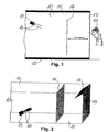
- Figs. 1-4 illustrate a room or shop having a pair of opposed side walls 10, a ceiling 11 and a floor 12.
- An end wall comprises a show window or display window 13.
- a screen 14 extends transversely to the side walls 10 and substantially parallel to and spaced from the window 13, for example with a distance of 4-5 m.
- the screen 14 is a net-like or perforated fabric or sheet material, for example bridal veil or tulle.
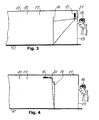
- a video projector 15 with a light funnel or light screens 16 projects moving pictures onto the screen 14. In the embodiments shown in Figs. 1, 2 and 4 the projector projects light onto the back side of the screen 14, i.e. the side facing away from the window 13.
- the space 17 behind the screen 14 is kept dark, and parts of the room in front of the screen 14 are preferably illuminated by spot lights, not shown.
- a person or viewer 18 standing outside the room or shop and looking through the window 13 can then neither see the screen 14 nor the projector 15. However, the viewer will see the projected moving object or person in the middle of the room like a hologram.
- a light trap or screen 19 may be arranged at the upper end of the window 13 to suppress or catch reflected or scattered light.
- the projector 15 projects images or moving pictures onto the backside of the screen via a prism 20, which could be replaced by one or mirrors, if desired.
- the arrangements shown in Fig. 4 functions similar to the arrangements illustrated in Figs 1 and 2 .
- the projector 15 projects images, such as moving pictures, onto the front side of the screen 14, which means the side opposite to the window 13.
- the projector 15 is positioned at the upper part of the end wall containing the window 13 so that the projector is invisible to the viewer 18 standing at the outside of the window 13.
- the images are projected onto the screen 14 via one or more light reflectors or mirrors 21. It has been found that by this arrangement a similar effect may be obtained as when the images are projected onto the backside of the screen 14 as illustrated in Figs. 1, 2 and 4 and as described above.
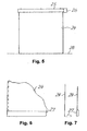
- Figs. 5-7 illustrate a projection screen 24 and an associated reel device 25, which may be mounted at a ceiling and from which the screen may be unreeled.
- the reel device 25 comprises an electric motor 26, which may be operated so as to reel or to unreel the screen 24.
- the opposite vertical edges of the screen are preferably guided in slits or slots so as to be invisible to the user.
- a metal strip 27 is preferably connected to the lower edge of the screen so as to ensure that the screen is kept tight and that the lower edge of the screen 24 is held in contact with a floor surface 28, when the screen is in its unreeled position.
- Fig. 7 shows alternative positions of the metal strip 27 when contacting the floor surface, and in order to keep the strip 27 in the desired position permanent magnets may be mounted at the floor surface to attract the iron strip 27.
- Figs. 8-10 illustrate an alternative projection screen arrangement which is mounted on a floor surface.
- the arrangement comprises a pair of spaced uprights or columns 29 and 30 extending substantially vertically from the floor surface 28.
- the upright 29 may function as a reel device 25 containing a reel 31 for reeling a projection screen 24, which may be unreeled so as to extend between the uprights as shown in Fig. 8 .
- From the reel 31 the screen is passed around a guide roller 32 which to a certain degree is movable parallel to the plane of the extended projection screen 24 and spring biased in a direction so as to tighten the screen.
- the reel 31 is easily exchangeable, so that a fractured or otherwise defect screen may easily be replaced with a new one, and the reel may include a rewinding device, such as a rewinding spring device of the type conventionally used in roller blinds.
- Handles 33 with hook-shaped connecting members 34 are mounted on the free end of the screen 24 as shown in Fig. 9 .
- the hook-shaped connecting members 34 may releasably engage with complementary shaped retaining members 35 formed on the upright 30.
- the screen 24 is preferably made from tulle, and in such case the upper and lower edges of the screen made be reinforced and kept straight by a string or wire 36 ( Fig. 10 ) attached thereto, preferably by being passed through successive openings of the net-like screen 24.
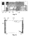
- FIG. 11 illustrates how the image projecting arrangement according to the invention may be used in a shop or showroom.
- a projection screen arrangement of the type shown in Figs. 5-7 or in Figs. 8-10 may be mounted in the room such that the screen 24 is spaced from and extends in substantially in the same direction as a window 37 forming part of the walls defining the room.
- An activation unit for example in the form of a touch screen 38, is arranged inside and immediately adjacent to the window, so that the touch screen may be activated by a person 39 standing at the outer side of the window 37. The person or viewer 39 may then select one of a plurality of video shows by touching the window opposite to the corresponding field or section of the touch screen 38.
- one or more models 40 may show a collection of clothing sold in the shop and selected by the viewer 39 by means of the touch screen 38.
- the screen 24 may be reeled and hidden within the reel device 25 in daytime when the shop is open, while the arrangement may be active at night after office hours.
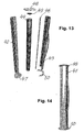
- the projection screen system or arrangement shown in Figs. 12 - 14 comprises a tubular upright or column 41, which may have, for example, a polygonal, such as an octagonal, cross-sectional shape, vide Fig. 14 .
- the tubular column 41 is longitudinally divided into stationary and movable column parts 42 and 43, respectively, which may be releaseably interconnected in a storage position as shown in Fig. 14 .
- the column 41 contains a reel 44 with a web of a fabric screen 45, such as tulle or bridal veil, winded thereon.
- the reel 44 is rotatably mounted in the stationary column part 42, and the free end of the fabric screen is connected to a strip 46 ( Fig. 13 ), which may be connected to the movable column part 43.
- the stationary column part comprises a base plate or foot plate 47, which is adopted to be fixed to a floor surface so as to hold the stationary column part in an upright or vertical position, and a top plate or cover plate 48 with a rewinding device 49 for rewinding the fabric screen 45 onto the reel 44 when released.
- the movable column part 43 also has a base plate or foot plate 50 integrally connected thereto and adapted to releasably engage with a fastening device (not shown) on the floor surface, so that the movable column part 43 may be held releasably in an upright or vertical position on the floor surface and transversely spaced from the stationary column part 42 with the screen 45 extending between the column parts as illustrated in Fig. 12 .
- the arrangement according to the invention could also be used outdoors at night, and the screen onto which the moving pictures are projected may be arranged horizontally above the heads of viewers, and the projector should then be arranged above or below the screen, as desired. Even though the method and arrangement according to the present invention may be used for any suitable purpose, such as for teaching, security and for military purposes, it has been found especially valuable for advertising or sales promotion purposes.
Abstract
Description
- The present invention relates to a method for projecting images, preferably moving pictures, onto a projection medium.
- Conventionally, such images are projected onto a solid, light reflecting screen, and the projected image may be viewed from the same side of the screen as that on which the projector is placed. However, it has also been proposed to use a mist of liquid or solid particles as a projection medium, cf.
DE-A- 31 30 638 . This kind of projection medium is difficult to control and is not suited for indoor use. - The present invention provides a new method for projecting images onto a projection medium such that this medium may be made invisible or substantially invisible, whereby a viewer will get the impression that the images, such as moving pictures, projected are freely suspended or floating in space.
- This is obtained by the arrangenent according to the invention, wherein the images are projected onto a projection medium comprising a screen forming an open, light penetrable structure being formed by a plurality of adjacent small light penetrable and light reflecting areas, respectively, as defined by claim 1.
- The open structure of the screen may be formed by a plurality of adjacent small light penetrable and light reflecting areas, respectively. Thus, like conventional projection screens the screen according to the invention may be a solid screen made from an opaque material which has been made transparent in a plurality of small areas so as to form the open structure, or the screen may be made from a transparent material which has been made opaque in selected areas so as to form the open structure. Thus, the desired pattern of opaque areas may be imprinted on the transparent sheet or the material may be made non-transparent in any other suitable manner. As an example, the screen may be formed by a transparent plastic film, parts of which have been made opaque.
- In the presently preferred embodiment, however, the projection medium comprises a screen of a perforated or net-like structure. Such screen has opposite first and second side surfaces, and, preferably, the screen has such a perforated or net-like structure that the projected images may be watched by a viewer from the second side surface of the screen when these images are projected onto the first side surface of the screen. Alternatively or additionally, the perforated or net-like structure of the screen may be such that the screen becomes substantially invisible to a viewer watching the projected images against a dark background from a position spaced from said first or second side surface of the screen.
- It has been found that when the screen has such a net-like or perforated structure the projected images may be watched from any of the opposite sides of the screen, and that the screen may be made substantially invisible to a viewer watching the projected images, which are preferably moving pictures, against a dark background from a position spaced from the screen. Preferably, the transition between the outline of the objects, persons or animals projected and the dark background is blurred or faded.
- When the space in which the screen is located and illuminated properly, the projection medium may be made invisible to the viewer and the projected images or moving pictures may in a ghost-like or hologram-like manner look like freely floating in the space or room in which the projection medium is arranged. The images being projected may, for example, be objects, persons and/or other living beings, and the objects or living beings to be highlighted are preferably depicted on a dark or black background (black level 0). Preferably, the transition between the outline of the objects or living beings and the dark background is blurred. Furthermore, residual light from a projector projecting the images should preferably be masked or screened, for example by means of a special lens or by means of a specially shaped light funnel (black wrap) through which the images are projected.
- The images may be computer generated or projected from a video projector or a computer controlled projector onto one side surface of the projection medium, possibly via one or more mirrors and/or prisms. The projector may then be placed at a convenient location where it is not immediately visible to the viewer or viewers.
- Opposite sides of the projection medium may be watched at the same time by first and second viewers positioned in front of and spaced from opposite sides, respectively, of the medium. Especially in this case the images projected onto the projection medium or screen may form part of a computer game. In the latter case the viewers may activate control means, such as pedals, steering wheels, joysticks, stepping panels or the like, and thereby interact with the game performance.
- The openings or perforations in the net-like or perforated structure of the screen are mutually separated by solid partition parts. These solid parts should preferably have a width, which is only a small fraction of the maximum dimension of the openings or perforations. This means that the total area of the openings or perforations should preferably substantially exceed half the area of the screen and preferably be 2/3 or more. The single opening or perforation should not be too large. Thus, the openings or perforations of the screen should preferably have a maximum dimension in the range of 0.5-2.5 mm, preferably 1-2 mm and more preferred about 1.2-1.5 mm. The screen is preferably white or light and non-glossy.
- Each of the openings or perforations may have any shape or outline, and even though preferred they need not be identical. As examples, the openings or perforations may have a circular or a polygonal, such as a hexagonal, rectangular, square or triangular, shape or outline.
- In practice it has been found that tulle, such as bridal veil or bridal tulle, with a net-like structure defining hexagonal openings is very suitable for use as the screen.
- It has been found that a proper veil-like nylon fabric for use as a screen in the method according to the invention is marketed by John Heathcoat & Co. Ltd., Tiverton, Devon, England under the Quality Number A1027 F.
- In order to make the screen invisible to the viewer the space defined behind said first side of the screen is preferably kept darker than the side of the screen being watched. Preferably the illumination of the said space is only 10-30 % of the illumination of the side of projection medium facing the viewer.
- The images are suitably projected on the screen by means of a projector, and the images are preferably projected in a direction defining an acute angle with said first surface of the screen. The projector may then be positioned adjacent to the ceiling, a wall or the floor of a room in which the screen is arranged, whereby the projector may be placed concealed or invisible to the viewer. Of course the projector may, alternatively, be concealed in other manner, for example covered by a screen.
- The projection medium or screen on which the images are projected may be arranged in a horizontal, oblique or a vertical plane. Thus, the screen may, for example, be horizontal and be arranged above the viewer. In such case moving pictures showing for example airplanes or other flying objects may be projected onto the screen from the upper or lower side thereof. As another example, the screen may be arranged in a room so as to divide the same into first and second chambers defined by said first and second surfaces, respectively, of the screen. A projector may be arranged in the first chamber, which is preferably kept darker than the second surface of the screen, which may be arranged opposite to and spaced from a show window or a display window of a shop or store. In the latter case the moving pictures being projected may, for example, be a model wearing and changing clothes, which are for sale in the store.
- According to another aspect the present invention also provides an image projecting arrangement, comprising means for defining a projection medium comprising a screen forming an open, light penetrable structure, which is formed by a plurality of adjacent small light penetrable and light reflecting areas, respectively, and a projector for projecting the images onto said medium. This projection medium or screen may be of any of the above mentioned types and structures.
- Furthermore, according to a third aspect the present invention provides use of a screen forming an open, light penetrable structure, which comprises a plurality of small light reflecting, preferably differently orientated surface parts, and a plurality of adjacent small light penetrable areas, respectively, as a projection medium for moving pictures.
- Such medium may be defined in any of the manners described above and may, for example, comprise a screen, wherein the open structure has been formed by a plurality of adjacent small light penetrable and light reflecting areas, respectively. Thus, as examples, the screen may be formed by a transparent film, parts of which have been made opaque, or from a fabric or sheet material having a perforated or net-like structure. Preferably, in the latter case the screen has such a perforated or net-like structure that images projected on one side surface thereof may be watched by a viewer from the opposite side surface of the screen, and/or that the screen becomes substantially invisible to a viewer watching the projected images against a dark background from a position spaced from the screen.
- According to a fourth aspect the present invention provides a projection screen arrangement comprising first and second spaced uprights extending from a floor or ground surface, said first upright comprising a reel for reeling and unreeling a projection screen thereon, the free end of the screen comprising connecting means for releasably connecting the free end of the screen to the second upright, and biasing means for tightening the screen when extending between the first and second uprights. The uprights may be in the form of sculptural, aesthetic columns, so that they do not unfavourably influence the visual impression of the room when the screen is not in use. The connection means may be of a very simple type and may, for example, comprise at least one, preferably two, hook member for engaging with the second upright. The screen may be of a conventional type or any of the screen types described above. However, it is preferably made from tulle. In the latter case it may be necessary to reinforce or strengthen the upper and/or lower edge of the screen by means of a suitable string or line.
- The invention will now be further described with reference to the enclosed diagrammatic drawings, wherein
-
Fig. 1 is a vertical sectional view of a room or shop with an arrangement according to the invention, -
Fig. 2 is a perspective side view of the arrangement shown inFig. 1 , -
Figs. 3 and 4 are vertical sectional views of a shop or a room with further embodiments of the arrangement according to the invention, the projectors being arranged in different positions, -
Fig. 5 is a projection screen with a reel device mounted at a ceiling, -
Fig. 6 is a fragment of the lower part of the screen shown inFig. 5 , -
Fig. 7 shows vertical sectional views of the lower part of the screen illustrated inFigs. 5 and 6 , -
Fig. 8 is a front view of a projection screen system mounted on a floor surface, -
Fig. 9 is a top view of the screen system ofFig. 8 shown in an enlarged scale, -
Fig. 10 is a fragmentary view of the upper edge of the projection screen, -
Fig. 11 a shop or show room with a projection arrangement, which may be operated or activated by a viewer positioned outside the room, -
Fig. 12 is front view of a further embodiment of projection screen system as that illustrated inFigs. 8 and 9 in a position of use, -
Fig. 13 is an exploded view of the system shown inFig. 12 , and -
Fig. 14 is the projection screen system illustrated inFigs. 12 and13 in a storage position. -
Figs. 1-4 illustrate a room or shop having a pair ofopposed side walls 10, aceiling 11 and afloor 12. An end wall comprises a show window ordisplay window 13. In the embodiments illustrated inFigs. 1-4 ascreen 14 extends transversely to theside walls 10 and substantially parallel to and spaced from thewindow 13, for example with a distance of 4-5 m. - The
screen 14 is a net-like or perforated fabric or sheet material, for example bridal veil or tulle. Avideo projector 15 with a light funnel or light screens 16 (shown inFigs. 1 and 2 ) projects moving pictures onto thescreen 14. In the embodiments shown inFigs. 1, 2 and4 the projector projects light onto the back side of thescreen 14, i.e. the side facing away from thewindow 13. Thespace 17 behind thescreen 14 is kept dark, and parts of the room in front of thescreen 14 are preferably illuminated by spot lights, not shown. - A person or
viewer 18 standing outside the room or shop and looking through thewindow 13 can then neither see thescreen 14 nor theprojector 15. However, the viewer will see the projected moving object or person in the middle of the room like a hologram. As indicated inFig. 2 a light trap orscreen 19 may be arranged at the upper end of thewindow 13 to suppress or catch reflected or scattered light. - In the embodiment shown in
Fig. 4 theprojector 15 projects images or moving pictures onto the backside of the screen via aprism 20, which could be replaced by one or mirrors, if desired. In other respects the arrangements shown inFig. 4 functions similar to the arrangements illustrated inFigs 1 and 2 . - In the arrangement illustrated in
Fig. 3 theprojector 15 projects images, such as moving pictures, onto the front side of thescreen 14, which means the side opposite to thewindow 13. Theprojector 15 is positioned at the upper part of the end wall containing thewindow 13 so that the projector is invisible to theviewer 18 standing at the outside of thewindow 13. The images are projected onto thescreen 14 via one or more light reflectors or mirrors 21. It has been found that by this arrangement a similar effect may be obtained as when the images are projected onto the backside of thescreen 14 as illustrated inFigs. 1, 2 and4 and as described above. -
Figs. 5-7 illustrate aprojection screen 24 and an associatedreel device 25, which may be mounted at a ceiling and from which the screen may be unreeled. Thereel device 25 comprises an electric motor 26, which may be operated so as to reel or to unreel thescreen 24. The opposite vertical edges of the screen are preferably guided in slits or slots so as to be invisible to the user. As shown inFigs. 6 and 7 , ametal strip 27 is preferably connected to the lower edge of the screen so as to ensure that the screen is kept tight and that the lower edge of thescreen 24 is held in contact with afloor surface 28, when the screen is in its unreeled position.Fig. 7 shows alternative positions of themetal strip 27 when contacting the floor surface, and in order to keep thestrip 27 in the desired position permanent magnets may be mounted at the floor surface to attract theiron strip 27. -
Figs. 8-10 illustrate an alternative projection screen arrangement which is mounted on a floor surface. The arrangement comprises a pair of spaced uprights orcolumns floor surface 28. The upright 29 may function as areel device 25 containing areel 31 for reeling aprojection screen 24, which may be unreeled so as to extend between the uprights as shown inFig. 8 . From thereel 31 the screen is passed around aguide roller 32 which to a certain degree is movable parallel to the plane of theextended projection screen 24 and spring biased in a direction so as to tighten the screen. Preferably, thereel 31 is easily exchangeable, so that a fractured or otherwise defect screen may easily be replaced with a new one, and the reel may include a rewinding device, such as a rewinding spring device of the type conventionally used in roller blinds.Handles 33 with hook-shaped connectingmembers 34 are mounted on the free end of thescreen 24 as shown inFig. 9 . The hook-shaped connectingmembers 34 may releasably engage with complementary shaped retainingmembers 35 formed on theupright 30. Thescreen 24 is preferably made from tulle, and in such case the upper and lower edges of the screen made be reinforced and kept straight by a string or wire 36 (Fig. 10 ) attached thereto, preferably by being passed through successive openings of the net-like screen 24. -
Fig. 11 illustrates how the image projecting arrangement according to the invention may be used in a shop or showroom. A projection screen arrangement of the type shown inFigs. 5-7 or inFigs. 8-10 may be mounted in the room such that thescreen 24 is spaced from and extends in substantially in the same direction as awindow 37 forming part of the walls defining the room. An activation unit, for example in the form of atouch screen 38, is arranged inside and immediately adjacent to the window, so that the touch screen may be activated by aperson 39 standing at the outer side of thewindow 37. The person orviewer 39 may then select one of a plurality of video shows by touching the window opposite to the corresponding field or section of thetouch screen 38. By using the method according the present invention individuals and or objects may now be presented as if they were moving freely in the room. Thus, as an example one ormore models 40 may show a collection of clothing sold in the shop and selected by theviewer 39 by means of thetouch screen 38. Thescreen 24 may be reeled and hidden within thereel device 25 in daytime when the shop is open, while the arrangement may be active at night after office hours. - The projection screen system or arrangement shown in
Figs. 12 - 14 comprises a tubular upright or column 41, which may have, for example, a polygonal, such as an octagonal, cross-sectional shape, videFig. 14 . The tubular column 41 is longitudinally divided into stationary andmovable column parts Fig. 14 . The column 41 contains areel 44 with a web of afabric screen 45, such as tulle or bridal veil, winded thereon. Thereel 44 is rotatably mounted in thestationary column part 42, and the free end of the fabric screen is connected to a strip 46 (Fig. 13 ), which may be connected to themovable column part 43. The stationary column part comprises a base plate orfoot plate 47, which is adopted to be fixed to a floor surface so as to hold the stationary column part in an upright or vertical position, and a top plate or coverplate 48 with arewinding device 49 for rewinding thefabric screen 45 onto thereel 44 when released. - The
movable column part 43 also has a base plate orfoot plate 50 integrally connected thereto and adapted to releasably engage with a fastening device (not shown) on the floor surface, so that themovable column part 43 may be held releasably in an upright or vertical position on the floor surface and transversely spaced from thestationary column part 42 with thescreen 45 extending between the column parts as illustrated inFig. 12 . - It should be understood that the arrangement according to the invention could also be used outdoors at night, and the screen onto which the moving pictures are projected may be arranged horizontally above the heads of viewers, and the projector should then be arranged above or below the screen, as desired. Even though the method and arrangement according to the present invention may be used for any suitable purpose, such as for teaching, security and for military purposes, it has been found especially valuable for advertising or sales promotion purposes.
Claims (19)
- An image projecting arrangement comprising
a screen (14, 24, 45) arranged in a room having a floor (12), a pair of opposed side walls (10), and an end wall comprising a window (13), said screen extending transversely to the side walls and substantially parallel to and spaced from the window, the screen forming an open, light penetrable structure, which is formed by a plurality of adjacent small light penetrable and light reflecting areas, respectively, and
a projector (15) for projecting images onto said screen,
characterised in that the arrangement is for advertising and/or sales promotion purposes, said room being a shop or a show room, In which first and second spaced uprights (29, 30) extend from a floor or ground surface (28) of the show room or shop, said first upright (29) comprising a reel (31) for reeling and unreeling the projection screen (45) thereon, the free end of the screen comprising connecting means (34) for releasably connecting the free end of the screen to the second upright (30), and biasing means (32) for tightening the screen when extending between the first and second uprights. - An arrangement according to claim 1, wherein the connection means comprise at least one hook member (34) for engaging with the second upright (30).
- An arrangement according to claim 1 or 2, wherein the upper and lower edges of the screen are reinforced by strings or lines (36).
- An arrangement according to any of the claims 1 - 3, wherein the screen is formed by a transparent film, parts of which have been made opaque or light reflecting.
- An arrangement according to any of the claims 1 - 3, wherein the screen (14, 24, 45) is of a perforated or net-like structure.
- An arrangement according to claim 5, wherein the screen (14, 24, 45) has opposite first and second side surfaces and has such an open structure that the projected images may be watched by a viewer (18) from the second side surface of the screen.
- An arrangement according to claim 5 or 6, wherein the screen (14, 24, 45) has opposite first and second side surfaces and has such an open structure that the screen becomes substantially invisible to a viewer (18) watching the projected images against a more dark background from a position spaced from said first or second side surface of the screen.
- An arrangement according to any of the claims 1 - 7, wherein the projector is adapted to project images in the form of moving pictures.
- An arrangement according to any of the claims 1 - 8, wherein the light penetrable areas, the openings or perforations of the screen are mutually separated by partition parts having a width being only a small fraction of the maximum dimension of the penetrable areas, openings or perforations.
- An arrangement according to any of the claims 1 - 9, wherein the penetrable areas, the openings or perforations of the screen each has a maximum dimension in the range of 0.5 - 2.5 mm, preferably 1 - 2 mm and more preferred about 1.2 - 1.5 mm.
- An arrangement according to any of the claims 1 - 10, wherein the penetrable areas, the openings or perforations have a polygonal and/or circular shape or outline.
- An arrangement according to claim 11, wherein the openings or perforations have a hexagonal, rectangular, square, and/or triangular shape.
- An arrangement according to claim 5, wherein the screen is made from tulle.
- An arrangement according to any of the claims 1 - 13, wherein the projector (15) is positioned so as to project the images in a direction defining an acute angle with a first surface of the screen.
- An arrangement according to any of the claims 1 - 14, wherein the images are projected on the screen by means of the projector (15) arranged in a position so as not to be visible to the viewer (18) or viewers.
- An arrangement according to any of the claims 1 - 15, further comprising a control device (38) for controlling the operation of the projector positioned so as to be accessible to a viewer (39) outside the shop or showroom.
- An arrangement according to claim 16, wherein the control device comprises a touch screen (38) by means of which a viewer may select the images or image program to be projected.
- An arrangement according to claim 16 or 17, wherein the control device is arranged at the inner side of the transparent window and may be activated from the outer side of the window.
- An arrangement according to any of the claims 1 - 18, wherein the projection screen (14, 24, 45) is arranged in the shop or room so as to divide the same into first and second chambers defined by opposite first and second surfaces of the screen, respectively, the projector (15) being arranged in the first chamber (17), which is preferably kept darker than the second chamber, the second surface of the screen being arranged opposite to and spaced from a show window or display window (37).
Applications Claiming Priority (7)
| Application Number | Priority Date | Filing Date | Title |
|---|---|---|---|
| DK200201938 | 2002-12-18 | ||
| DKPA200201938 | 2002-12-18 | ||
| DK200202015 | 2002-12-28 | ||
| DKPA200202015 | 2002-12-28 | ||
| DK200300328 | 2003-03-03 | ||
| DKPA200300328 | 2003-03-03 | ||
| PCT/DK2003/000892 WO2004055590A2 (en) | 2002-12-18 | 2003-12-17 | A method and an arrangement for projecting images and a projection screen arrangement |
Publications (2)
| Publication Number | Publication Date |
|---|---|
| EP1583995A2 EP1583995A2 (en) | 2005-10-12 |
| EP1583995B1 true EP1583995B1 (en) | 2010-11-03 |
Family
ID=32600579
Family Applications (1)
| Application Number | Title | Priority Date | Filing Date |
|---|---|---|---|
| EP03779750A Expired - Lifetime EP1583995B1 (en) | 2002-12-18 | 2003-12-17 | A method and an arrangement for projecting images and projection screen arrangement |
Country Status (7)
| Country | Link |
|---|---|
| US (1) | US7184209B2 (en) |
| EP (1) | EP1583995B1 (en) |
| AT (1) | ATE487161T1 (en) |
| AU (1) | AU2003287910A1 (en) |
| DE (1) | DE60334847D1 (en) |
| DK (1) | DK1583995T3 (en) |
| WO (1) | WO2004055590A2 (en) |
Families Citing this family (7)
| Publication number | Priority date | Publication date | Assignee | Title |
|---|---|---|---|---|
| US8458028B2 (en) | 2002-10-16 | 2013-06-04 | Barbaro Technologies | System and method for integrating business-related content into an electronic game |
| KR100679037B1 (en) * | 2005-06-28 | 2007-02-05 | 삼성전자주식회사 | Method and apparatus for performing fast handover in wireless Networks |
| GB0522150D0 (en) * | 2005-10-31 | 2005-12-07 | Musion Systems Ltd | Projection apparatus and method |
| GB2433331A (en) * | 2005-12-02 | 2007-06-20 | Mediazest Plc | A projection screen |
| US9459458B2 (en) | 2012-02-21 | 2016-10-04 | 360Brandvision, Inc. | Transparent sound dampening projection screen |
| US10042242B2 (en) * | 2014-12-29 | 2018-08-07 | Arc Co., Ltd. | Transparent screen and method for manufacturing transparent screen |
| WO2017119543A1 (en) | 2016-01-04 | 2017-07-13 | 엘지전자(주) | Electronic device |
Family Cites Families (11)
| Publication number | Priority date | Publication date | Assignee | Title |
|---|---|---|---|---|
| GB396714A (en) * | 1932-02-06 | 1933-08-08 | Trans Lux Daylight Picture | Improvements in or relating to projection screens |
| US2107038A (en) * | 1936-04-06 | 1938-02-01 | Lennard Mclennan | Projection screen |
| US3961839A (en) * | 1972-06-29 | 1976-06-08 | Brobst Clarence O | Indoor-outdoor image projection system |
| DE3130638A1 (en) | 1981-07-30 | 1983-02-17 | Szymanski, Ralf | Projection screen for preferably large-area reproduction |
| US5573325A (en) * | 1994-06-08 | 1996-11-12 | Encountarium, Inc. | Multi-sensory theatrical presentation structure |
| US5982537A (en) * | 1996-08-16 | 1999-11-09 | Sony Corporation | Speaker apparatus with a picture projecting screen |
| JPH10340061A (en) * | 1997-04-07 | 1998-12-22 | Masahiko Hayashi | Video appreviation facility |
| JP3385207B2 (en) * | 1997-09-05 | 2003-03-10 | 泉株式会社 | Portable screen |
| JPH11160795A (en) * | 1997-11-28 | 1999-06-18 | Sony Corp | Screen device |
| AU4615999A (en) * | 1999-06-25 | 2001-01-31 | Peter Werhahn-Wunderlich | Device for displacing 3-dimensional objects in the projection area of a projection system |
| JP4630436B2 (en) * | 2000-09-19 | 2011-02-09 | 株式会社ジャムコ | Projection screen |
-
2003
- 2003-12-17 AU AU2003287910A patent/AU2003287910A1/en not_active Abandoned
- 2003-12-17 AT AT03779750T patent/ATE487161T1/en not_active IP Right Cessation
- 2003-12-17 DE DE60334847T patent/DE60334847D1/en not_active Expired - Lifetime
- 2003-12-17 WO PCT/DK2003/000892 patent/WO2004055590A2/en not_active Application Discontinuation
- 2003-12-17 DK DK03779750.3T patent/DK1583995T3/en active
- 2003-12-17 EP EP03779750A patent/EP1583995B1/en not_active Expired - Lifetime
-
2004
- 2004-04-26 US US10/739,796 patent/US7184209B2/en not_active Expired - Fee Related
Also Published As
| Publication number | Publication date |
|---|---|
| US20050078365A1 (en) | 2005-04-14 |
| WO2004055590A2 (en) | 2004-07-01 |
| ATE487161T1 (en) | 2010-11-15 |
| AU2003287910A1 (en) | 2004-07-09 |
| WO2004055590A3 (en) | 2004-09-10 |
| EP1583995A2 (en) | 2005-10-12 |
| DK1583995T3 (en) | 2011-02-07 |
| US7184209B2 (en) | 2007-02-27 |
| WO2004055590B1 (en) | 2004-11-04 |
| DE60334847D1 (en) | 2010-12-16 |
Similar Documents
| Publication | Publication Date | Title |
|---|---|---|
| RU2126705C1 (en) | Erection for show of theatrical performances with influence upon different organs of sense of spectator (variants) | |
| JP4047172B2 (en) | Reflective projection screen | |
| JP2930219B2 (en) | A device that displays moving images on the background of the stage | |
| KR100695247B1 (en) | Back face transmission screen | |
| US8145048B2 (en) | Photo booth and improvements thereto | |
| JP6267764B2 (en) | Equipment for displaying information media especially for advertising purposes | |
| RU97100160A (en) | CONSTRUCTION FOR SHOWING THEATERAL PERFORMANCES WITH INFLUENCE ON VARIOUS BODIES OF SENSITIVITY OF THE VIEWERS | |
| EP1583995B1 (en) | A method and an arrangement for projecting images and projection screen arrangement | |
| BE1018388A5 (en) | DEVICE FOR VISUALIZING IMAGES. | |
| US7545563B2 (en) | Lightweight compactible projection screen for trade show and other uses | |
| CN108475005B (en) | Device for displaying three-dimensional images and videos of a real environment | |
| US4414767A (en) | Room decoration | |
| GB2437928A (en) | Projection apparatus | |
| US20060150452A1 (en) | Multilayer three-dimensional display | |
| US4725135A (en) | Optical entertainment of amusement structure and device | |
| US4180934A (en) | Perforated stencil sign panel | |
| KR20180103223A (en) | Interaction system between contents and a performer, and a stage comprising the same | |
| KR200187903Y1 (en) | Transparent window advertisement display apparatus | |
| GB2084461A (en) | Decorative room display | |
| US9557633B2 (en) | Display apparatus | |
| WO1986003683A1 (en) | Optical entertainment or amusement structure and device | |
| KR100901104B1 (en) | Screen apparatus having printing display function | |
| JPH11219137A (en) | Decorative device | |
| GB2433331A (en) | A projection screen | |
| CN105788487A (en) | Columnar hanging type projection advertisement board |
Legal Events
| Date | Code | Title | Description |
|---|---|---|---|
| PUAI | Public reference made under article 153(3) epc to a published international application that has entered the european phase |
Free format text: ORIGINAL CODE: 0009012 |
|
| 17P | Request for examination filed |
Effective date: 20050714 |
|
| AK | Designated contracting states |
Kind code of ref document: A2 Designated state(s): AT BE BG CH CY CZ DE DK EE ES FI FR GB GR HU IE IT LI LU MC NL PT RO SE SI SK |
|
| AX | Request for extension of the european patent |
Extension state: AL LT LV MK |
|
| RIN1 | Information on inventor provided before grant (corrected) |
Inventor name: CORELL, MORTEN Inventor name: SIMONSEN, PETER, ALLAN |
|
| RBV | Designated contracting states (corrected) |
Designated state(s): AT BE BG CH CY CZ DE DK EE ES FI FR GB GR HU IE IT LI LU MC NL PT RO SE SI SK TR |
|
| RIN1 | Information on inventor provided before grant (corrected) |
Inventor name: CORELL, MORTEN Inventor name: SIMONSEN, PETER, ALLAN |
|
| GRAP | Despatch of communication of intention to grant a patent |
Free format text: ORIGINAL CODE: EPIDOSNIGR1 |
|
| GRAS | Grant fee paid |
Free format text: ORIGINAL CODE: EPIDOSNIGR3 |
|
| GRAA | (expected) grant |
Free format text: ORIGINAL CODE: 0009210 |
|
| AK | Designated contracting states |
Kind code of ref document: B1 Designated state(s): AT BE BG CH CY CZ DE DK EE ES FI FR GB GR HU IE IT LI LU MC NL PT RO SE SI SK TR |
|
| AX | Request for extension of the european patent |
Extension state: AL LT LV MK |
|
| REG | Reference to a national code |
Ref country code: GB Ref legal event code: FG4D |
|
| REG | Reference to a national code |
Ref country code: CH Ref legal event code: EP |
|
| REG | Reference to a national code |
Ref country code: IE Ref legal event code: FG4D |
|
| REF | Corresponds to: |
Ref document number: 60334847 Country of ref document: DE Date of ref document: 20101216 Kind code of ref document: P |
|
| REG | Reference to a national code |
Ref country code: DK Ref legal event code: T3 |
|
| REG | Reference to a national code |
Ref country code: NL Ref legal event code: VDEP Effective date: 20101103 |
|
| REG | Reference to a national code |
Ref country code: GR Ref legal event code: EP Ref document number: 20110400252 Country of ref document: GR Effective date: 20110317 |
|
| LTIE | Lt: invalidation of european patent or patent extension |
Effective date: 20101103 |
|
| PG25 | Lapsed in a contracting state [announced via postgrant information from national office to epo] |
Ref country code: SE Free format text: LAPSE BECAUSE OF FAILURE TO SUBMIT A TRANSLATION OF THE DESCRIPTION OR TO PAY THE FEE WITHIN THE PRESCRIBED TIME-LIMIT Effective date: 20101103 Ref country code: AT Free format text: LAPSE BECAUSE OF FAILURE TO SUBMIT A TRANSLATION OF THE DESCRIPTION OR TO PAY THE FEE WITHIN THE PRESCRIBED TIME-LIMIT Effective date: 20101103 Ref country code: NL Free format text: LAPSE BECAUSE OF FAILURE TO SUBMIT A TRANSLATION OF THE DESCRIPTION OR TO PAY THE FEE WITHIN THE PRESCRIBED TIME-LIMIT Effective date: 20101103 Ref country code: SI Free format text: LAPSE BECAUSE OF FAILURE TO SUBMIT A TRANSLATION OF THE DESCRIPTION OR TO PAY THE FEE WITHIN THE PRESCRIBED TIME-LIMIT Effective date: 20101103 Ref country code: BG Free format text: LAPSE BECAUSE OF FAILURE TO SUBMIT A TRANSLATION OF THE DESCRIPTION OR TO PAY THE FEE WITHIN THE PRESCRIBED TIME-LIMIT Effective date: 20110203 Ref country code: FI Free format text: LAPSE BECAUSE OF FAILURE TO SUBMIT A TRANSLATION OF THE DESCRIPTION OR TO PAY THE FEE WITHIN THE PRESCRIBED TIME-LIMIT Effective date: 20101103 Ref country code: PT Free format text: LAPSE BECAUSE OF FAILURE TO SUBMIT A TRANSLATION OF THE DESCRIPTION OR TO PAY THE FEE WITHIN THE PRESCRIBED TIME-LIMIT Effective date: 20110303 |
|
| PG25 | Lapsed in a contracting state [announced via postgrant information from national office to epo] |
Ref country code: ES Free format text: LAPSE BECAUSE OF FAILURE TO SUBMIT A TRANSLATION OF THE DESCRIPTION OR TO PAY THE FEE WITHIN THE PRESCRIBED TIME-LIMIT Effective date: 20110214 Ref country code: BE Free format text: LAPSE BECAUSE OF FAILURE TO SUBMIT A TRANSLATION OF THE DESCRIPTION OR TO PAY THE FEE WITHIN THE PRESCRIBED TIME-LIMIT Effective date: 20101103 Ref country code: EE Free format text: LAPSE BECAUSE OF FAILURE TO SUBMIT A TRANSLATION OF THE DESCRIPTION OR TO PAY THE FEE WITHIN THE PRESCRIBED TIME-LIMIT Effective date: 20101103 Ref country code: MC Free format text: LAPSE BECAUSE OF NON-PAYMENT OF DUE FEES Effective date: 20101231 Ref country code: CZ Free format text: LAPSE BECAUSE OF FAILURE TO SUBMIT A TRANSLATION OF THE DESCRIPTION OR TO PAY THE FEE WITHIN THE PRESCRIBED TIME-LIMIT Effective date: 20101103 |
|
| REG | Reference to a national code |
Ref country code: CH Ref legal event code: PL |
|
| PG25 | Lapsed in a contracting state [announced via postgrant information from national office to epo] |
Ref country code: SK Free format text: LAPSE BECAUSE OF FAILURE TO SUBMIT A TRANSLATION OF THE DESCRIPTION OR TO PAY THE FEE WITHIN THE PRESCRIBED TIME-LIMIT Effective date: 20101103 Ref country code: RO Free format text: LAPSE BECAUSE OF FAILURE TO SUBMIT A TRANSLATION OF THE DESCRIPTION OR TO PAY THE FEE WITHIN THE PRESCRIBED TIME-LIMIT Effective date: 20101103 |
|
| PLBE | No opposition filed within time limit |
Free format text: ORIGINAL CODE: 0009261 |
|
| STAA | Information on the status of an ep patent application or granted ep patent |
Free format text: STATUS: NO OPPOSITION FILED WITHIN TIME LIMIT |
|
| REG | Reference to a national code |
Ref country code: DK Ref legal event code: EBP |
|
| 26N | No opposition filed |
Effective date: 20110804 |
|
| GBPC | Gb: european patent ceased through non-payment of renewal fee |
Effective date: 20110203 |
|
| PG25 | Lapsed in a contracting state [announced via postgrant information from national office to epo] |
Ref country code: CH Free format text: LAPSE BECAUSE OF NON-PAYMENT OF DUE FEES Effective date: 20101231 Ref country code: IE Free format text: LAPSE BECAUSE OF NON-PAYMENT OF DUE FEES Effective date: 20101217 Ref country code: LI Free format text: LAPSE BECAUSE OF NON-PAYMENT OF DUE FEES Effective date: 20101231 |
|
| REG | Reference to a national code |
Ref country code: DE Ref legal event code: R097 Ref document number: 60334847 Country of ref document: DE Effective date: 20110804 |
|
| PG25 | Lapsed in a contracting state [announced via postgrant information from national office to epo] |
Ref country code: IT Free format text: LAPSE BECAUSE OF NON-PAYMENT OF DUE FEES Effective date: 20101217 |
|
| PG25 | Lapsed in a contracting state [announced via postgrant information from national office to epo] |
Ref country code: DK Free format text: LAPSE BECAUSE OF NON-PAYMENT OF DUE FEES Effective date: 20110228 Ref country code: GB Free format text: LAPSE BECAUSE OF NON-PAYMENT OF DUE FEES Effective date: 20110203 |
|
| PG25 | Lapsed in a contracting state [announced via postgrant information from national office to epo] |
Ref country code: CY Free format text: LAPSE BECAUSE OF FAILURE TO SUBMIT A TRANSLATION OF THE DESCRIPTION OR TO PAY THE FEE WITHIN THE PRESCRIBED TIME-LIMIT Effective date: 20101103 |
|
| PG25 | Lapsed in a contracting state [announced via postgrant information from national office to epo] |
Ref country code: HU Free format text: LAPSE BECAUSE OF FAILURE TO SUBMIT A TRANSLATION OF THE DESCRIPTION OR TO PAY THE FEE WITHIN THE PRESCRIBED TIME-LIMIT Effective date: 20110504 Ref country code: LU Free format text: LAPSE BECAUSE OF NON-PAYMENT OF DUE FEES Effective date: 20101217 |
|
| PGFP | Annual fee paid to national office [announced via postgrant information from national office to epo] |
Ref country code: DE Payment date: 20130620 Year of fee payment: 10 |
|
| PGFP | Annual fee paid to national office [announced via postgrant information from national office to epo] |
Ref country code: GR Payment date: 20130628 Year of fee payment: 10 Ref country code: FR Payment date: 20130702 Year of fee payment: 10 Ref country code: IT Payment date: 20130626 Year of fee payment: 10 Ref country code: TR Payment date: 20130612 Year of fee payment: 11 |
|
| REG | Reference to a national code |
Ref country code: DE Ref legal event code: R119 Ref document number: 60334847 Country of ref document: DE |
|
| REG | Reference to a national code |
Ref country code: GR Ref legal event code: ML Ref document number: 20110400252 Country of ref document: GR Effective date: 20140702 |
|
| REG | Reference to a national code |
Ref country code: DE Ref legal event code: R119 Ref document number: 60334847 Country of ref document: DE Effective date: 20140701 |
|
| REG | Reference to a national code |
Ref country code: FR Ref legal event code: ST Effective date: 20140829 |
|
| PG25 | Lapsed in a contracting state [announced via postgrant information from national office to epo] |
Ref country code: GR Free format text: LAPSE BECAUSE OF NON-PAYMENT OF DUE FEES Effective date: 20140702 Ref country code: DE Free format text: LAPSE BECAUSE OF NON-PAYMENT OF DUE FEES Effective date: 20140701 |
|
| PG25 | Lapsed in a contracting state [announced via postgrant information from national office to epo] |
Ref country code: FR Free format text: LAPSE BECAUSE OF NON-PAYMENT OF DUE FEES Effective date: 20131231 |
|
| PG25 | Lapsed in a contracting state [announced via postgrant information from national office to epo] |
Ref country code: IT Free format text: LAPSE BECAUSE OF NON-PAYMENT OF DUE FEES Effective date: 20131217 |
|
| PG25 | Lapsed in a contracting state [announced via postgrant information from national office to epo] |
Ref country code: TR Free format text: LAPSE BECAUSE OF NON-PAYMENT OF DUE FEES Effective date: 20141217 |