EP1583588B1 - Methods and apparatus for controlling hazardous and/or flammable materials - Google Patents
Methods and apparatus for controlling hazardous and/or flammable materials Download PDFInfo
- Publication number
- EP1583588B1 EP1583588B1 EP03812508.4A EP03812508A EP1583588B1 EP 1583588 B1 EP1583588 B1 EP 1583588B1 EP 03812508 A EP03812508 A EP 03812508A EP 1583588 B1 EP1583588 B1 EP 1583588B1
- Authority
- EP
- European Patent Office
- Prior art keywords
- housing
- hazard
- control system
- compartments
- control material
- Prior art date
- Legal status (The legal status is an assumption and is not a legal conclusion. Google has not performed a legal analysis and makes no representation as to the accuracy of the status listed.)
- Expired - Lifetime
Links
- 239000000463 material Substances 0.000 title claims description 175
- 238000000034 method Methods 0.000 title claims description 13
- 231100001261 hazardous Toxicity 0.000 title description 4
- 239000002828 fuel tank Substances 0.000 claims description 47
- 238000007373 indentation Methods 0.000 claims description 17
- 239000000843 powder Substances 0.000 claims description 14
- 230000004044 response Effects 0.000 claims description 11
- 238000005520 cutting process Methods 0.000 claims description 6
- 238000001125 extrusion Methods 0.000 claims description 2
- 238000000465 moulding Methods 0.000 claims description 2
- 238000003856 thermoforming Methods 0.000 claims description 2
- 230000001133 acceleration Effects 0.000 claims 1
- 238000010102 injection blow moulding Methods 0.000 claims 1
- 238000001746 injection moulding Methods 0.000 claims 1
- 239000003981 vehicle Substances 0.000 description 31
- 239000012530 fluid Substances 0.000 description 26
- 239000000446 fuel Substances 0.000 description 24
- 239000003921 oil Substances 0.000 description 16
- 239000000126 substance Substances 0.000 description 15
- 239000000853 adhesive Substances 0.000 description 13
- 230000001070 adhesive effect Effects 0.000 description 13
- 238000005192 partition Methods 0.000 description 12
- CURLTUGMZLYLDI-UHFFFAOYSA-N Carbon dioxide Chemical compound O=C=O CURLTUGMZLYLDI-UHFFFAOYSA-N 0.000 description 11
- PPBRXRYQALVLMV-UHFFFAOYSA-N Styrene Chemical compound C=CC1=CC=CC=C1 PPBRXRYQALVLMV-UHFFFAOYSA-N 0.000 description 10
- 230000006378 damage Effects 0.000 description 9
- 230000007246 mechanism Effects 0.000 description 9
- 239000004033 plastic Substances 0.000 description 9
- 229920003023 plastic Polymers 0.000 description 9
- 238000004519 manufacturing process Methods 0.000 description 7
- UIIMBOGNXHQVGW-UHFFFAOYSA-M Sodium bicarbonate Chemical compound [Na+].OC([O-])=O UIIMBOGNXHQVGW-UHFFFAOYSA-M 0.000 description 6
- 239000011521 glass Substances 0.000 description 6
- 229920000642 polymer Polymers 0.000 description 6
- 239000002253 acid Substances 0.000 description 5
- NIXOWILDQLNWCW-UHFFFAOYSA-N acrylic acid group Chemical group C(C=C)(=O)O NIXOWILDQLNWCW-UHFFFAOYSA-N 0.000 description 5
- 239000001569 carbon dioxide Substances 0.000 description 5
- 229910002092 carbon dioxide Inorganic materials 0.000 description 5
- 239000003795 chemical substances by application Substances 0.000 description 5
- 230000008878 coupling Effects 0.000 description 5
- 238000010168 coupling process Methods 0.000 description 5
- 238000005859 coupling reaction Methods 0.000 description 5
- 239000007789 gas Substances 0.000 description 5
- 239000000383 hazardous chemical Substances 0.000 description 5
- 239000004593 Epoxy Substances 0.000 description 4
- QAOWNCQODCNURD-UHFFFAOYSA-N Sulfuric acid Chemical compound OS(O)(=O)=O QAOWNCQODCNURD-UHFFFAOYSA-N 0.000 description 4
- 229910052782 aluminium Inorganic materials 0.000 description 4
- XAGFODPZIPBFFR-UHFFFAOYSA-N aluminium Chemical compound [Al] XAGFODPZIPBFFR-UHFFFAOYSA-N 0.000 description 4
- 239000003518 caustics Substances 0.000 description 4
- 239000000919 ceramic Substances 0.000 description 4
- 238000004880 explosion Methods 0.000 description 4
- 238000009434 installation Methods 0.000 description 4
- 239000007788 liquid Substances 0.000 description 4
- VNWKTOKETHGBQD-UHFFFAOYSA-N methane Chemical compound C VNWKTOKETHGBQD-UHFFFAOYSA-N 0.000 description 4
- 230000003472 neutralizing effect Effects 0.000 description 4
- 239000003380 propellant Substances 0.000 description 4
- 239000007921 spray Substances 0.000 description 4
- QTBSBXVTEAMEQO-UHFFFAOYSA-N Acetic acid Chemical compound CC(O)=O QTBSBXVTEAMEQO-UHFFFAOYSA-N 0.000 description 3
- IJGRMHOSHXDMSA-UHFFFAOYSA-N Atomic nitrogen Chemical compound N#N IJGRMHOSHXDMSA-UHFFFAOYSA-N 0.000 description 3
- 229920001247 Reticulated foam Polymers 0.000 description 3
- VYPSYNLAJGMNEJ-UHFFFAOYSA-N Silicium dioxide Chemical compound O=[Si]=O VYPSYNLAJGMNEJ-UHFFFAOYSA-N 0.000 description 3
- LFVGISIMTYGQHF-UHFFFAOYSA-N ammonium dihydrogen phosphate Chemical compound [NH4+].OP(O)([O-])=O LFVGISIMTYGQHF-UHFFFAOYSA-N 0.000 description 3
- 229910000387 ammonium dihydrogen phosphate Inorganic materials 0.000 description 3
- 239000002131 composite material Substances 0.000 description 3
- 238000013461 design Methods 0.000 description 3
- 238000001514 detection method Methods 0.000 description 3
- 239000000835 fiber Substances 0.000 description 3
- 239000000945 filler Substances 0.000 description 3
- 238000010438 heat treatment Methods 0.000 description 3
- 229910052751 metal Inorganic materials 0.000 description 3
- 239000002184 metal Substances 0.000 description 3
- 239000000203 mixture Substances 0.000 description 3
- 239000006012 monoammonium phosphate Substances 0.000 description 3
- 235000019837 monoammonium phosphate Nutrition 0.000 description 3
- 239000004417 polycarbonate Substances 0.000 description 3
- 229920000515 polycarbonate Polymers 0.000 description 3
- -1 polyphenylene Polymers 0.000 description 3
- NLKNQRATVPKPDG-UHFFFAOYSA-M potassium iodide Chemical compound [K+].[I-] NLKNQRATVPKPDG-UHFFFAOYSA-M 0.000 description 3
- 238000007789 sealing Methods 0.000 description 3
- 238000000926 separation method Methods 0.000 description 3
- 229910000030 sodium bicarbonate Inorganic materials 0.000 description 3
- 235000017557 sodium bicarbonate Nutrition 0.000 description 3
- 230000032258 transport Effects 0.000 description 3
- XLYOFNOQVPJJNP-UHFFFAOYSA-N water Substances O XLYOFNOQVPJJNP-UHFFFAOYSA-N 0.000 description 3
- 229910001868 water Inorganic materials 0.000 description 3
- XKRFYHLGVUSROY-UHFFFAOYSA-N Argon Chemical compound [Ar] XKRFYHLGVUSROY-UHFFFAOYSA-N 0.000 description 2
- VTYYLEPIZMXCLO-UHFFFAOYSA-L Calcium carbonate Chemical compound [Ca+2].[O-]C([O-])=O VTYYLEPIZMXCLO-UHFFFAOYSA-L 0.000 description 2
- VEXZGXHMUGYJMC-UHFFFAOYSA-N Hydrochloric acid Chemical compound Cl VEXZGXHMUGYJMC-UHFFFAOYSA-N 0.000 description 2
- 229920000784 Nomex Polymers 0.000 description 2
- CDBYLPFSWZWCQE-UHFFFAOYSA-L Sodium Carbonate Chemical compound [Na+].[Na+].[O-]C([O-])=O CDBYLPFSWZWCQE-UHFFFAOYSA-L 0.000 description 2
- 150000007513 acids Chemical class 0.000 description 2
- 230000006978 adaptation Effects 0.000 description 2
- 238000000071 blow moulding Methods 0.000 description 2
- 238000002485 combustion reaction Methods 0.000 description 2
- 238000005336 cracking Methods 0.000 description 2
- 238000007599 discharging Methods 0.000 description 2
- 238000005516 engineering process Methods 0.000 description 2
- 239000011888 foil Substances 0.000 description 2
- 239000013056 hazardous product Substances 0.000 description 2
- 239000003915 liquefied petroleum gas Substances 0.000 description 2
- 238000011068 loading method Methods 0.000 description 2
- 239000012528 membrane Substances 0.000 description 2
- 239000003595 mist Substances 0.000 description 2
- 230000000116 mitigating effect Effects 0.000 description 2
- 239000003345 natural gas Substances 0.000 description 2
- 239000004763 nomex Substances 0.000 description 2
- 230000036961 partial effect Effects 0.000 description 2
- 239000002245 particle Substances 0.000 description 2
- BWHMMNNQKKPAPP-UHFFFAOYSA-L potassium carbonate Chemical compound [K+].[K+].[O-]C([O-])=O BWHMMNNQKKPAPP-UHFFFAOYSA-L 0.000 description 2
- 230000001681 protective effect Effects 0.000 description 2
- 238000003860 storage Methods 0.000 description 2
- 230000035882 stress Effects 0.000 description 2
- 230000008646 thermal stress Effects 0.000 description 2
- 231100000331 toxic Toxicity 0.000 description 2
- 230000002588 toxic effect Effects 0.000 description 2
- 238000007666 vacuum forming Methods 0.000 description 2
- ZCYVEMRRCGMTRW-UHFFFAOYSA-N 7553-56-2 Chemical compound [I] ZCYVEMRRCGMTRW-UHFFFAOYSA-N 0.000 description 1
- 239000004114 Ammonium polyphosphate Substances 0.000 description 1
- WKBOTKDWSSQWDR-UHFFFAOYSA-N Bromine atom Chemical compound [Br] WKBOTKDWSSQWDR-UHFFFAOYSA-N 0.000 description 1
- OKTJSMMVPCPJKN-UHFFFAOYSA-N Carbon Chemical compound [C] OKTJSMMVPCPJKN-UHFFFAOYSA-N 0.000 description 1
- 240000004670 Glycyrrhiza echinata Species 0.000 description 1
- 235000001453 Glycyrrhiza echinata Nutrition 0.000 description 1
- 235000006200 Glycyrrhiza glabra Nutrition 0.000 description 1
- 235000017382 Glycyrrhiza lepidota Nutrition 0.000 description 1
- UFHFLCQGNIYNRP-UHFFFAOYSA-N Hydrogen Chemical compound [H][H] UFHFLCQGNIYNRP-UHFFFAOYSA-N 0.000 description 1
- 229920000271 Kevlar® Polymers 0.000 description 1
- 239000004677 Nylon Substances 0.000 description 1
- 229920000265 Polyparaphenylene Polymers 0.000 description 1
- 239000004743 Polypropylene Substances 0.000 description 1
- ZLMJMSJWJFRBEC-UHFFFAOYSA-N Potassium Chemical compound [K] ZLMJMSJWJFRBEC-UHFFFAOYSA-N 0.000 description 1
- 206010039203 Road traffic accident Diseases 0.000 description 1
- UIIMBOGNXHQVGW-DEQYMQKBSA-M Sodium bicarbonate-14C Chemical compound [Na+].O[14C]([O-])=O UIIMBOGNXHQVGW-DEQYMQKBSA-M 0.000 description 1
- 235000017899 Spathodea campanulata Nutrition 0.000 description 1
- XSQUKJJJFZCRTK-UHFFFAOYSA-N Urea Chemical compound NC(N)=O XSQUKJJJFZCRTK-UHFFFAOYSA-N 0.000 description 1
- 208000027418 Wounds and injury Diseases 0.000 description 1
- 230000003213 activating effect Effects 0.000 description 1
- 239000000654 additive Substances 0.000 description 1
- 230000000996 additive effect Effects 0.000 description 1
- 239000002390 adhesive tape Substances 0.000 description 1
- 239000000956 alloy Substances 0.000 description 1
- 229910045601 alloy Inorganic materials 0.000 description 1
- WNROFYMDJYEPJX-UHFFFAOYSA-K aluminium hydroxide Chemical compound [OH-].[OH-].[OH-].[Al+3] WNROFYMDJYEPJX-UHFFFAOYSA-K 0.000 description 1
- DIZPMCHEQGEION-UHFFFAOYSA-H aluminium sulfate (anhydrous) Chemical compound [Al+3].[Al+3].[O-]S([O-])(=O)=O.[O-]S([O-])(=O)=O.[O-]S([O-])(=O)=O DIZPMCHEQGEION-UHFFFAOYSA-H 0.000 description 1
- VCNTUJWBXWAWEJ-UHFFFAOYSA-J aluminum;sodium;dicarbonate Chemical compound [Na+].[Al+3].[O-]C([O-])=O.[O-]C([O-])=O VCNTUJWBXWAWEJ-UHFFFAOYSA-J 0.000 description 1
- 235000019826 ammonium polyphosphate Nutrition 0.000 description 1
- 229920001276 ammonium polyphosphate Polymers 0.000 description 1
- 238000013459 approach Methods 0.000 description 1
- 229910052786 argon Inorganic materials 0.000 description 1
- 239000011230 binding agent Substances 0.000 description 1
- 230000015572 biosynthetic process Effects 0.000 description 1
- 239000007767 bonding agent Substances 0.000 description 1
- GDTBXPJZTBHREO-UHFFFAOYSA-N bromine Substances BrBr GDTBXPJZTBHREO-UHFFFAOYSA-N 0.000 description 1
- 229910052794 bromium Inorganic materials 0.000 description 1
- 229910000019 calcium carbonate Inorganic materials 0.000 description 1
- 239000004202 carbamide Substances 0.000 description 1
- 235000013877 carbamide Nutrition 0.000 description 1
- 230000002860 competitive effect Effects 0.000 description 1
- 238000010276 construction Methods 0.000 description 1
- 238000007796 conventional method Methods 0.000 description 1
- 229910001647 dawsonite Inorganic materials 0.000 description 1
- 230000001419 dependent effect Effects 0.000 description 1
- 239000002274 desiccant Substances 0.000 description 1
- 239000003599 detergent Substances 0.000 description 1
- 229910001873 dinitrogen Inorganic materials 0.000 description 1
- 230000000694 effects Effects 0.000 description 1
- 229920001971 elastomer Polymers 0.000 description 1
- 239000003623 enhancer Substances 0.000 description 1
- 230000003203 everyday effect Effects 0.000 description 1
- 239000004744 fabric Substances 0.000 description 1
- 230000002349 favourable effect Effects 0.000 description 1
- 239000011152 fibreglass Substances 0.000 description 1
- 238000011049 filling Methods 0.000 description 1
- 239000006260 foam Substances 0.000 description 1
- 239000004088 foaming agent Substances 0.000 description 1
- 229910021485 fumed silica Inorganic materials 0.000 description 1
- 239000003502 gasoline Substances 0.000 description 1
- 239000003292 glue Substances 0.000 description 1
- 239000010439 graphite Substances 0.000 description 1
- 229910002804 graphite Inorganic materials 0.000 description 1
- 229910052736 halogen Inorganic materials 0.000 description 1
- 150000002367 halogens Chemical class 0.000 description 1
- UKACHOXRXFQJFN-UHFFFAOYSA-N heptafluoropropane Chemical compound FC(F)C(F)(F)C(F)(F)F UKACHOXRXFQJFN-UHFFFAOYSA-N 0.000 description 1
- 239000001257 hydrogen Substances 0.000 description 1
- 229910052739 hydrogen Inorganic materials 0.000 description 1
- 230000003116 impacting effect Effects 0.000 description 1
- 230000001976 improved effect Effects 0.000 description 1
- 230000000977 initiatory effect Effects 0.000 description 1
- 238000002347 injection Methods 0.000 description 1
- 239000007924 injection Substances 0.000 description 1
- 208000014674 injury Diseases 0.000 description 1
- 238000003780 insertion Methods 0.000 description 1
- 230000037431 insertion Effects 0.000 description 1
- 229940004975 interceptor Drugs 0.000 description 1
- 229910052740 iodine Inorganic materials 0.000 description 1
- 239000011630 iodine Substances 0.000 description 1
- 238000005304 joining Methods 0.000 description 1
- 239000004761 kevlar Substances 0.000 description 1
- 239000002655 kraft paper Substances 0.000 description 1
- 229940010454 licorice Drugs 0.000 description 1
- 239000003562 lightweight material Substances 0.000 description 1
- 238000002844 melting Methods 0.000 description 1
- 230000008018 melting Effects 0.000 description 1
- VUZPPFZMUPKLLV-UHFFFAOYSA-N methane;hydrate Chemical compound C.O VUZPPFZMUPKLLV-UHFFFAOYSA-N 0.000 description 1
- 239000004005 microsphere Substances 0.000 description 1
- 238000002156 mixing Methods 0.000 description 1
- 238000012986 modification Methods 0.000 description 1
- 230000004048 modification Effects 0.000 description 1
- 238000012544 monitoring process Methods 0.000 description 1
- 239000010705 motor oil Substances 0.000 description 1
- 230000007935 neutral effect Effects 0.000 description 1
- 229910052757 nitrogen Inorganic materials 0.000 description 1
- UQQALTRHPDPRQC-UHFFFAOYSA-N nitrogen tribromide Chemical compound BrN(Br)Br UQQALTRHPDPRQC-UHFFFAOYSA-N 0.000 description 1
- FZIONDGWZAKCEX-UHFFFAOYSA-N nitrogen triiodide Chemical group IN(I)I FZIONDGWZAKCEX-UHFFFAOYSA-N 0.000 description 1
- 229920001778 nylon Polymers 0.000 description 1
- 230000003287 optical effect Effects 0.000 description 1
- 239000004482 other powder Substances 0.000 description 1
- 239000000123 paper Substances 0.000 description 1
- 230000000149 penetrating effect Effects 0.000 description 1
- 230000035515 penetration Effects 0.000 description 1
- GTLACDSXYULKMZ-UHFFFAOYSA-N pentafluoroethane Chemical compound FC(F)C(F)(F)F GTLACDSXYULKMZ-UHFFFAOYSA-N 0.000 description 1
- 229920001155 polypropylene Polymers 0.000 description 1
- 229910052700 potassium Inorganic materials 0.000 description 1
- 239000011591 potassium Substances 0.000 description 1
- 239000011736 potassium bicarbonate Substances 0.000 description 1
- 229910000028 potassium bicarbonate Inorganic materials 0.000 description 1
- 235000015497 potassium bicarbonate Nutrition 0.000 description 1
- 229910000027 potassium carbonate Inorganic materials 0.000 description 1
- 235000011181 potassium carbonates Nutrition 0.000 description 1
- TYJJADVDDVDEDZ-UHFFFAOYSA-M potassium hydrogencarbonate Chemical compound [K+].OC([O-])=O TYJJADVDDVDEDZ-UHFFFAOYSA-M 0.000 description 1
- 235000007715 potassium iodide Nutrition 0.000 description 1
- 238000002360 preparation method Methods 0.000 description 1
- 230000008569 process Effects 0.000 description 1
- 238000012545 processing Methods 0.000 description 1
- 230000001737 promoting effect Effects 0.000 description 1
- 230000005855 radiation Effects 0.000 description 1
- 230000009467 reduction Effects 0.000 description 1
- 238000009877 rendering Methods 0.000 description 1
- 239000012858 resilient material Substances 0.000 description 1
- 230000031070 response to heat Effects 0.000 description 1
- 230000000284 resting effect Effects 0.000 description 1
- 230000000979 retarding effect Effects 0.000 description 1
- 238000007493 shaping process Methods 0.000 description 1
- 239000000377 silicon dioxide Substances 0.000 description 1
- 229910000029 sodium carbonate Inorganic materials 0.000 description 1
- 239000007787 solid Substances 0.000 description 1
- 125000006850 spacer group Chemical group 0.000 description 1
- 238000005507 spraying Methods 0.000 description 1
- 230000000087 stabilizing effect Effects 0.000 description 1
- 239000013589 supplement Substances 0.000 description 1
- 230000000153 supplemental effect Effects 0.000 description 1
- 230000001629 suppression Effects 0.000 description 1
- 239000002341 toxic gas Substances 0.000 description 1
- 238000012546 transfer Methods 0.000 description 1
- VPAYJEUHKVESSD-UHFFFAOYSA-N trifluoroiodomethane Chemical compound FC(F)(F)I VPAYJEUHKVESSD-UHFFFAOYSA-N 0.000 description 1
- 239000011800 void material Substances 0.000 description 1
Images




Classifications
-
- A—HUMAN NECESSITIES
- A62—LIFE-SAVING; FIRE-FIGHTING
- A62C—FIRE-FIGHTING
- A62C3/00—Fire prevention, containment or extinguishing specially adapted for particular objects or places
- A62C3/07—Fire prevention, containment or extinguishing specially adapted for particular objects or places in vehicles, e.g. in road vehicles
-
- A—HUMAN NECESSITIES
- A62—LIFE-SAVING; FIRE-FIGHTING
- A62C—FIRE-FIGHTING
- A62C2/00—Fire prevention or containment
-
- A—HUMAN NECESSITIES
- A62—LIFE-SAVING; FIRE-FIGHTING
- A62C—FIRE-FIGHTING
- A62C35/00—Permanently-installed equipment
- A62C35/02—Permanently-installed equipment with containers for delivering the extinguishing substance
- A62C35/06—Containers destroyed or opened by falling
-
- A—HUMAN NECESSITIES
- A62—LIFE-SAVING; FIRE-FIGHTING
- A62C—FIRE-FIGHTING
- A62C99/00—Subject matter not provided for in other groups of this subclass
- A62C99/0009—Methods of extinguishing or preventing the spread of fire by cooling down or suffocating the flames
- A62C99/0045—Methods of extinguishing or preventing the spread of fire by cooling down or suffocating the flames using solid substances, e.g. sand, ashes; using substances forming a crust
-
- A—HUMAN NECESSITIES
- A62—LIFE-SAVING; FIRE-FIGHTING
- A62D—CHEMICAL MEANS FOR EXTINGUISHING FIRES OR FOR COMBATING OR PROTECTING AGAINST HARMFUL CHEMICAL AGENTS; CHEMICAL MATERIALS FOR USE IN BREATHING APPARATUS
- A62D1/00—Fire-extinguishing compositions; Use of chemical substances in extinguishing fires
-
- A—HUMAN NECESSITIES
- A62—LIFE-SAVING; FIRE-FIGHTING
- A62D—CHEMICAL MEANS FOR EXTINGUISHING FIRES OR FOR COMBATING OR PROTECTING AGAINST HARMFUL CHEMICAL AGENTS; CHEMICAL MATERIALS FOR USE IN BREATHING APPARATUS
- A62D1/00—Fire-extinguishing compositions; Use of chemical substances in extinguishing fires
- A62D1/0007—Solid extinguishing substances
- A62D1/0014—Powders; Granules
Definitions
- the invention relates to methods and apparatus for controlling hazardous and/or flammable materials and the effects of such materials.
- Flammable and otherwise hazardous materials play an important role in the everyday lives of most people. Most people encounter flammable materials, such as gasoline, engine oil, and natural gas, and other hazardous materials, such as battery acid and concentrated detergents, without danger. Because the unsafe materials are contained, they typically present no problem for those that are nearby.
- the materials can injure or kill, such as when the container is damaged and the material escapes.
- hundreds of thousands of vehicular accidents occur each year on American highways.
- Many accident-related fire events occur when the region of the vehicle containing the fuel tank is impacted in an accident, spilling the fuel contents from the tank in the form of a spray, stream, and eventual pool around the vehicle.
- the highly ignitable spray mist generated upon impact may be exposed to ignition energy from sparks generated from vehicle deformation on impact for only a fraction of a second. This duration, however, may be long enough to ignite the fuel mist into a possible explosion, or more likely a fireball that ignites a developing pool of fuel surrounding the vehicle and create a more serious threat.
- the powder panels were demonstrated to effectively protect against many large ballistic incendiary threats with as little as about 0.254cm (0.1 inch) total thickness and about 0.01-0.03 kg mass per square metre (0.2-0.6 pounds mass per square foot). Other threats and conditions could require much thicker, heavier, systems if they worked at all. Some limitations in performance were seen against small threats that limited rupture damage to the panel and as a result limited the amount of powder suppressant released to extinguish the fire.
- US 4251579 describes a fire protection panel consisting of an array of cells, sandwiched between two flat facing sheets and containing a fire extinguishant.
- the cells are arranged in a honeycomb or lattice layout, with each cell sharing an adjoining wall with one of its neighbouring cells.
- the shared walls are permeable and/or have small notches in them to permit permeation of the extinguishant through the cells.
- US 5575339 teaches an expandable metal foil or net which is used in extinguishing surfaces fires.
- GB2255015A describes a valve and siphon assembly which is actuable to open and close a conduit to release a fire extinguishant.
- US20020020536A1 discloses various configurations and applications for a thin, breakable panel containing a dry chemical fire extinguishant, typically for use in transportation systems.
- US 3804292 discloses a fire-preventing fuel tank in which adjacent but separate volumes are provided inside the tank, one kind of volumes holding the fuel, whereas the other holds a substance (e.g. a halogen), which when admixed to the fuel, makes it non-flammable.
- a substance e.g. a halogen
- a hazard control system comprising a fuel tank, a control material and a housing, the housing being attached to or abutting an outer surface of the fuel tank.
- the housing is configured to deliver the control material in response to a trigger event.
- the housing has multiple rows of interconnected compartments containing the control material.
- the compartments have openings connected by ducts to allow flow of the control material between the interconnected compartments.
- the housing comprises two face sheets, at least one of the face sheets including multiple indentations. The two face sheets are joined so that one of the face sheets covers the indentations in the other face sheet to form the compartments and the ducts.
- the rows of interconnected compartments are parallel to a longitudinal axis of the face sheets.
- a method of controlling a hazard from a fuel tank comprises: providing a hazard control system by mounting a housing to an outer surface of the fuel tank, wherein the housing defines multiple interconnected compartments, the compartments having openings connected by ducts to allow flow of control material between the interconnected compartments; and disposing a control material in the housing.
- the housing comprises two face sheets, at least one of the face sheets including multiple indentations, the two face sheets joined so that one of the face sheets covers the indentations in the other face sheet to form the compartments and the ducts.
- the rows of interconnected compartments are parallel to a longitudinal axis of the face sheets.
- a hazard control system disclosed herein comprises a housing configured to contain a control material and deliver the control material to neutralize a hazard in response to a trigger event.
- the control material is an extinguishant for retarding fire.
- the housing contains the extinguishant and includes at least one surface configured to rupture in response to a trigger event, such as an impact.
- the housing may also include a surface configured to substantially mate with a surface of a vehicle, such as a fuel tank surface.
- the present invention is described partly in terms of functional components and various processing steps. Such functional components may be realized by any number of components configured to perform the specified functions and achieve the various results. For example, the present invention may employ various elements, materials, suppressants, neutralizing agents, and the like, which may carry out a variety of functions. In addition, the present invention may be practiced in conjunction with any number of applications, environments, hazardous materials, and trigger events, and the systems described are merely exemplary applications for the invention. Further, the present invention may employ any number of conventional techniques for manufacturing, assembling, mounting, and the like.
- a hazard control system 100 for controlling hazardous and/or flammable materials may be implemented in conjunction with a housing 102 containing a control material 104.
- the housing 102 is configured to contain the control material 104 and facilitate dispersal of the control material 104 in response to a trigger event, especially relatively large quantities of control material 104 for relatively large-scale events such as an impact, exposure to heat, or detection of a hazard.
- the control material 104 comprises one or more materials for controlling a hazard.
- the housing 102 may comprise any suitable apparatus for containing the control material 104 and facilitating dispersal of the control material 104 in response to the trigger event.
- the housing 102 may comprise a container configured to shatter, explode, or otherwise deteriorate, either entirely or in part, upon impact to release the control material 104.
- the housing 102 may comprise a rigid structure, a semi-rigid structure, a membrane, or a bladder.
- the housing 102 may be comprised of any suitable materials, for example glass, ceramic, or plastic that is designed to shatter upon impact.
- the housing 102 may be configured to promote dispersal of the control material 104, for example by scoring the housing 102 to promote fracturing of the scored surface in the event of an impact.
- the housing 102 may include additional mechanisms for promoting dispersal of the control material 104, such as one or more spring mechanisms, such as a leaf spring, compressed coil spring, a flat spring, an expandable material, configured to enhance the expansion of the housing 102 when the housing 102 is weakened or fractured by the trigger event.
- spring mechanisms such as a leaf spring, compressed coil spring, a flat spring, an expandable material, configured to enhance the expansion of the housing 102 when the housing 102 is weakened or fractured by the trigger event.
- multiple channels formed in the housing 102 include spring mechanisms to biased against a surface of the housing 102 to be impacted.
- the housing 102 suitably comprises two face sheets 106 sandwiching the control material 104.
- the face sheets 106 maintain the control material 104 in position, and may comprise any suitable configuration, such as a rigid sheet, a flexible cover, a flexible bladder, or any other appropriate system for maintaining the control material 104 in a selected position.
- the face sheets 106 may comprise any appropriate materials, including cellulosic material such as styrene, paper, glass, plastic, metal, ceramic, aluminum, nylon, glass fabric, fiberglass/epoxy, Kevlar, graphite tape, or a composite or combination of such materials.
- the face sheets 106 are suitably configured to react to a trigger event, such as an impact, a thermal event such as exposure to heat, or an optical event such as exposure to particular radiation.
- a trigger event such as an impact
- a thermal event such as exposure to heat
- an optical event such as exposure to particular radiation.
- the face sheets 106 are suitably configured to substantially completely shatter or otherwise rupture to promote total release of the control material 104.
- the housing 102 may also comprise malleable materials, so the housing 102 may be shaped and bent to fit various configurations.
- the face sheets 106 are rectangular sheets constructed of a lightweight and cost effective material, such as glass, ceramic, acrylic, and/or epoxy.
- the face sheets 106 are suitably mounted on a frame 108 to support the face sheets 106.
- the frame 108 may comprise any suitable structure, such as a rigid structure joined to the face sheets 106, an adhesive material like a caulk between the face sheets 106, or a rigid spacer.
- the frame 108 may be omitted and the face sheets 106 may be otherwise configured to maintain the position of the control material 104.
- the ends of the face sheets 106 may be taped adhesively, glued, or crimped, or the face sheets may be formed as a single unit, such as using blow molding, vacuum forming, or thermoforming to form the housing 102.
- the frame 108 is configured to support the face sheets 106 and maintain the control material 104 in position.
- the frame 108 suitably comprises a rigid structure having the same shape as the face sheets 106 and bonded to the face sheets 106.
- the frame 108 comprises a rigid rectangular frame 108 configured to support the face sheets 106.
- the face sheets 106 may be connected to the frame 108 in any suitable manner, for example using fasteners or a bonding agent.
- the face sheets 106 are bonded using an epoxy 110 or a similar adhesive. Other variations may be used to bond the face sheets 106 to the frame 108, such as hot glues and other chemical adhesives.
- the housing 102 may also include a core 112 configured to separate the control material 104 into multiple compartments.
- the core 112 may also maintain a desired space between the face sheets 106 and support the face sheets 106.
- the core 112 may be configured in any suitable manner.
- the core 112 may be configured in a honeycomb configuration to form individual compartments.
- the core 112 may comprise any appropriate materials, such as lightweight, rigid materials.
- the core 112 comprises aluminum or Nomex.
- the housing 102 contains the control material 104.
- the control material 104 is contained in the compartments formed by the core 112.
- the control material 104 may comprise one or more suitable materials for neutralizing a particular hazard, such as a fire, acid spill, or noxious gas release.
- the control material 104 may comprise a fire suppressant, such as monoammonium phosphate, mixed with an appropriate desiccant and/or flow enhancer such as a 1% concentration of micronized fumed silica.
- the suppressant may comprise sodium bicarbonate, potassium bicarbonate, potassium carbonate, urea-based powders, potassium dawsonite, ammonium polyphosphate, monoammonium phosphate, potassium iodide, or other powder suppressants or mixtures, or liquid or gaseous agents, such as water, nitrogen, carbon dioxide, argon, iodotrifluoromethane, heptafluoropropane, pentafluoroethane, or other gaseous agents or mixtures.
- the compartments of the core 112 are suitably totally filled to capacity, though some settling may occur after construction and installation, leaving some void space in the core 112.
- the control material 104 may be supplemented with a filler, such as a neutral, non-burning substance to occupy internal volume.
- the filler is configured to cover a large area while adding little weight.
- the filler may comprise, for example, silica dessicant, glass or plastic microspheres which may be filled with the control material 104 or remain empty, or other suitable lightweight material.
- control material 104 may be enhanced to facilitate dispersal and/or react to the trigger event.
- control material may be pressurized, for example with air, a gaseous control material 104, or other fluid to enhance dispersal of the control material 104.
- control material 104 may respond directly to the trigger event.
- the control material 104 may include an optically reactive, thermally reactive, or impact reactive material that causes the control material 104 to expand or otherwise deploy.
- the control material 104 may also be supplemented with or include a propellant to propel the control material 104 out of the housing 102 to enhance delivery.
- the control material 104 may be supplemented containers of gas, such as ambient or pressurized air or a fire suppressant gas, that when compressed by the impact, burst and provide a gust of air to help disperse the control material 14.
- the containers may comprise any suitable containers, such as enclosed tubes or balls of thin plastic or other suitable material.
- the propellant may comprise a material that, when exposed to air, generates an expanding volume of gas to propel the control material 104.
- the propellant may also comprise a fire suppressant material, such as carbon dioxide.
- the propellant may include different areas of the housing 102 that may contain separate materials.
- the materials may react to generate a propelling gas and, in some embodiments, a supplemental fire suppressant.
- the materials may comprise acetic acid and a sodium bicarbonate control material 104, which produces carbon dioxide when mixed.
- the material may comprise carbonic acid, which reacts to heat, such as due to a fire, by decomposing to water and carbon dioxide.
- Other materials may be used that create carbon dioxide and water when mixed, such as calcium carbonate and hydrochloric acid, or sodium carbonate and dilute sulfuric acid.
- Yet other materials may produce a fire suppressant foaming agent.
- the supplementary material or control material 104 may comprise sodium bicarbonate powder with a licorice additive, which mixed with aluminum sulfate will make a sticky, aluminum hydroxide foam.
- Other materials may comprise compositions of nitrogen triiodide or nitrogen tribromide powders or solids, possibly mixed with stabilizing binders, which when impacted convert to nitrogen gas and fire suppressing iodine or bromine gas.
- the hazard control system 100 may be attached to a hazard source, such as a fuel tank or other hazardous material storage unit in a vehicle, such as a car, bus, truck, aircraft, racing car, police car or van, military vehicle or craft, racing boat, rail car, tractor trailer, or heavy equipment.
- a hazard source such as a fuel tank or other hazardous material storage unit in a vehicle, such as a car, bus, truck, aircraft, racing car, police car or van, military vehicle or craft, racing boat, rail car, tractor trailer, or heavy equipment.
- a hazard source such as a fuel tank or other hazardous material storage unit in a vehicle, such as a car, bus, truck, aircraft, racing car, police car or van, military vehicle or craft, racing boat, rail car, tractor trailer, or heavy equipment.
- a highway vehicle 510 is suitably equipped with the hazard control system 100 by attaching the hazard control system 100 to the vehicle's fuel tank 514.
- the hazard control system 100 When deformed and ruptured, the hazard control system 100 releases the control material 104, such as a suppressant powder 516 comprising monoammonium phosphate, which tends to neutralize the area around the damaged and potentially leaking fuel tank 514 to inhibit fire initiation.
- the hazard control system 100 may be configured for any suitable environment or application, however, such walls that may be subject to impact, heat, or other hazard, exterior of buildings, near airport runways, within or upon hazardous material transports, and the like.
- the hazard control system 100 may be configured in any suitable manner for a particular application, such as to enhance or direct dispersal of the control material 104, facilitate adaptation to multiple applications, reduce weight and/or cost, fit to particular objects, mitigate one or more different hazards, and the like.
- an alternative housing 102 includes multiple channels 610.
- the channels 610 are suitably configured to contain the control material 104 for release.
- the channels 610 may be configured in any suitable manner and formed by any appropriate structure.
- the channels 610 may be formed by the core 112 or on one or more of the face sheets 106, the frame 108, and/or other parts of the housing 102.
- the channels 610 are formed by raised partitions formed on an interior surface of at least one of the face sheets 106. Consequently, no core 112 is included.
- the housing 102 may include the core 112 to form the channels 610, and the frame 108 may also include structure, such as protruding partitions or other suitable structure, to form all or part of the channels 610.
- the channels 610 may be formed in any appropriate manner to maintain the position of the control material 104, facilitate dispersal of the control material 104 upon occurrence of the trigger event, provide ease of manufacturing and/or installation, or any other purpose.
- the channels 610 are configured to form individual parallel channels 610.
- the channels 610 may be configured in a serpentine pattern, diagonal channels 610, a combination of diagonal, horizontal, vertical, and/or otherwise oriented channels 610.
- the channels 610 may run in any suitable direction, and may be interconnected.
- the channels 610 may run horizontally and vertically through the housing 102.
- the channels 610 are defined by partitions 1010.
- the partitions 1010 may also maintain separation between the face sheets 106, and may also provide attachment points for connecting the two face sheets 106 together, for example using an adhesive, to form the housing 102.
- the partitions 1010 may comprise any appropriate configuration, such as square, circular, or rectangular partitions, and may be formed in any suitable manner, such as by collectively forming a separate core 112 or by being formed on or attached to one or more face sheets 106.
- Such partitions may also be included in configurations using individual channels or compartments, such as channels or compartments that are hermetically sealed from one another, for example to provide additional rigidity.
- the housing 102 may also include structural components to provide rigidity, such as ribs formed in the housing.
- the face sheets 106 may be joined by an adhesive 1114 that has limited bond strength, sufficient only for normal operational environments. The limited strength of the adhesive suitably provides minimal impedance to crack propagation of the second face sheet 1112, facilitating separation of the second face sheet 1112 (in its entirety or in pieces) from the partitions 1010.
- the housing 102 edges may be sealed, for example using tape or caulk.
- the housing 102 of the present example is closed along an edge 610 with an end cap 810.
- the end cap 810 may be connected to the face sheets 106 in any suitable manner, for example by being snapped, glued, adhered, fastened, or otherwise attached to the edge 610.
- the end cap 810 may comprise any suitable material, such as rubber or other resilient material, to be pressed into the edge 610 of the housing 102.
- the housing 102 may include any appropriate materials to facilitate response to the trigger event, provide manufacturing efficiency, reduce weight, or satisfy any other appropriate criteria.
- the housing 102 may be configured to aid in its full discharge of extinguishing chemical in response to a trigger event including an impact.
- first face sheet 1110 and partitions 1010 may be formed of a first material that is relatively inexpensive and strong, such as in one piece of polycarbonate, and the second face sheet 1112 may comprise a material more prone to total breakage when impacted, such as acrylic or styrene.
- the housing 102 may be completely formed of a single material, such as acrylic, styrene, styrenics polymer, polyphenylene, polypropylene, and/or polycarbonate.
- the housing comprises a material having desired brittleness and durability and demonstrating favorable fabrication features, such as a plastic, alloy, ceramic, composite, metal, fiber, and/or glass.
- the particular material and configuration may be selected according to the particular application.
- the housing material may be treated to improve the various characteristics of the housing material.
- the housing may comprise a first material having desirable brittleness, such as acrylic, styrene, styrenics polymer, or the like, and a second polymer, such as a fiber, polycarbonate, or another type of acrylic, styrene, styrenics polymer, or the like, configured to improve the characteristics of the first material, such as the ductility to improve the workability of the material.
- the housing material may comprise a first styrenics polymer having a high brittleness and a second styrenics polymer mixed with the first to lower the melting temperature of the overall housing material and otherwise improve the manufacturing characteristics of the material.
- the ratio of the first material to the second material may be selected according to the desired characteristics of the housing.
- the second material may comprise only a small amount, such as about 10% by weight or less, of the overall material.
- the second material may comprise a larger amount, such as about 50% or more of the overall material.
- the first brittle material comprises about 60-80% of the overall material, and the second material comprises about 20-40% of the overall material.
- a suitable material may comprise approximately 70% of the first material and about 30% of the second material.
- the housing 102 includes multiple compartments for containing the control material 104.
- Each compartment is connected to one or more other compartments.
- each compartment may be individually filled with the control material 104.
- a compartment may be connected to another compartment so that both compartments may be filled by accessing a single compartment.
- Using multiple compartments suitably facilitates cutting the housing 102 to a selected size.
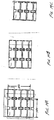
- the housing 102 includes multiple compartments 1210 containing the control material 104.
- the compartments 1210 may have any appropriate shape or size, such as approximately 7.62 cm (three inch) by 12.7 cm (five inch) rectangles.
- the housing 102 may form the compartments 1210 in any suitable manner.
- the compartments may be oriented in any manner, such as in rows parallel to an axis of the housing 102 or one or more of the face sheets 106.
- the housing 102 comprises two face sheets 106AB. At least one of the face sheets 106A includes multiple indentations to form the compartments 1210.
- the second face sheet 106B may be flat and the first face sheet 106A may be configured to include multiple indentations in the form of the compartments 1210.
- the compartments are suitably formed in rows parallel to a longitudinal axis of the face sheets 106.
- the two face sheets 106 are joined in any suitable manner so that the second face sheet 106B covers the indentations in the first face sheet 106A to form the compartments 1210.
- the compartments 1210 may, however, be formed in any suitable manner, such as by indentations in the second face sheet 103B, compartments formed by the core 112, independent bladders, a quilted bladder having multiple pockets, and the like.
- the compartments 1210 of the present embodiment are suitably connected to allow control material 104 to flow between the interconnected compartments 1210.
- the compartments 1210 may be interconnected in any suitable manner, such as via openings 1212 formed along one or more sides or other surfaces of the compartments 1210. Further, the openings 1212 are connected via one or more ducts 1214 connecting the openings 1212.
- the connections between the compartments 1210 may be implemented in any appropriate manner, such as using tubes attached to the compartments 1210, indentations in one or both of the face sheets 106, inclusion of a core 112 including the ducts 1214, and the like.
- the ducts 1214 are formed by indentations formed in the first face sheet 106A adjacent the indentations used to form the compartments 1210.
- the housing 102 may include any other desired structures to lend desired characteristics to the housing 102, such as to add stiffness, provide mounting surfaces or mechanisms, and the like.
- the first face sheet 106A may include rectangular indentations 1216 formed between the duct indentations 1214 to reduce the surface-to-surface contact between the face sheets 106 and promote crack propagation.
- each compartment 1210 along two edges of the housing 102 has at least one opening 1212 in one side which is connected to a duct 1214.
- Each compartment 1210 in the interior of the housing 102 and along the other two edges of the housing 102 has two openings 1212 on opposite sides of the compartment 1210.
- the openings 1212 are connected to the openings 1212 of the other compartments 1210 via the ducts 1214. Consequently, the control material 104 may move between the compartments 1210 through the openings 1212 and ducts 1214.
- the hazard control system 100 may be configured for a selected environment, a selected hazard, and/or a selected trigger event.
- the hazard control system 100 may be adapted for use with vehicle fuel tanks, storage tanks, fuel or chemical transfer lines, connectors, valves, and other components, oil containers and oil pans, battery compartments, engine compartments, or other applications.
- the hazard control system 100 may be configured to control flammable materials, toxic materials, caustic or corrosive materials, or other harmful materials.
- the hazard control system 100 may be configured to respond to any suitable trigger event, such as an impact, exposure to heat, exposure to a particular substance, or detection of a hazardous condition.
- the hazard control system 100 may be specifically configured for particular applications by shaping the housing 102 to conform to a selected surface.
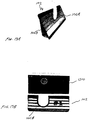
- an exemplary housing 102 substantially conforms to the exterior of the fuel tank.
- Clearance holes 310 accommodate fittings and exterior connections to the fuel tank.
- Grommets may also be installed in the clearance holes 310.
- the housing 102 may be configured to conform to the exterior shape of a fuel tank 1310 for police vehicle, such as a Ford Crown Victoria Police Interceptor, a bus, or a motorsports car.
- the first face sheet 106A has an outer surface that is configured to substantially mate with an exterior surface of the relevant fuel tank 1310, such as the top, rear, front, or side of the fuel tank 1310.
- the outer surface of the second face sheet 106B is configured to conform to the space requirements of the vehicle, such as to fit within the trunk of the vehicle.
- the housing 102 may be configured in any suitable manner to contain the control material 104, such as a fire suppressant, and shatter upon impact to release the control material 104.
- the housing 102 includes partitions formed in at least one of the face sheets 106 to form the compartments and suitably the ducts to interconnect the compartments as shown in Figure 12 .
- the face sheets 106 are suitably bonded together using an adhesive.
- an alternative hazard control system 100 comprises multiple housings 102. Each housing 102 conforms to the respective outer surfaces of the fuel tank 514, and may be attached to the fuel tank 514 in any suitable manner, such as via an adhesive. Alternatively, the hazard control system 100 may comprise a single structure or multiple interconnected structures surrounding the exterior of the fuel tank 514.
- the hazard control system 100 may be configured for adaptation to any particular application using one of more housings 102.
- multiple housings 102 may be attached to a fuel tank 514 or other structure to facilitate hazard mitigation.
- the housings 102 may be cut to a selected size and/or shape for a particular application.
- the housing 102 may be cut to an approximate desired width and length. Any compartments 1210 that are opened due to the cutting may be emptied of control material 104.
- a housing 102 is configured to be cut to a desired width 1412 and length 1410. To cut the width, the bottom portion may be cut away ( Figure 14B ). Although the cutting opens a series of compartments, several other compartments remain intact. Thus, the hazard control system 100 remains functional.
- a length of the housing 102 may be cut away ( Figure 14C ).
- multiple compartments may be opened, which may remain empty.
- the ducts leading to the empty compartments may then be closed, for example using putty, tape, caulk, epoxy, a resilient plug, or other mechanism.
- the control material 104 remains within several compartments of the housing 102.
- the compartment spacings are configured to permit cutting between the cells, to leave a sealing flange, such that only fill ports connecting the cells in each row remain exposed for filling. Consequently, the housing 102 may be cut after being filled with the control material 104 to reduce unfilled panel material around the perimeter.
- the hazard control system 100 may be attached to or associated with a hazard source in any appropriate manner. In various applications, the hazard control system 100 may be placed adjacent to or above the hazard source. Alternatively, the hazard control system 100 may be attached to or abut the hazard source. Any appropriate system or mechanism may fix the hazard control system 100 in position.
- the housing 102 may be adhesively attached directly to the fuel tank 514, such as via a peel-and-stick adhesive tape.
- the housing 102 may be attached by any other suitable mechanism, such as tape, straps, rivets, clips, hook-and-loop fasteners, or other fasteners.
- the hazard control system 100 may be adapted for a particular component that may be susceptible to causing a hazard.
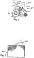
- the housing 102 is adapted to conform to a fuel pump 1510, such as for an internal combustion engine.
- the housing 102 is suitably configured to fit over the fuel pump 1510, such as by vacuum forming, blow molding, or other suitable process.
- the housing 102 may be connected to the fuel pump 1510, such as via a press fit, outer band clamps, or internal adhesive.
- the hazard control system 100 may also include a separate end plate 1512 that is attached (adhesively or otherwise) to the end of the housing 102 near the outer end of the fuel pump 1510, particularly if simple cylindrical geometries are applicable.
- the housing 102 may be configured according to any appropriate design to facilitate dispersal of the control material 104 in response to the trigger event.
- the housing 102 is configured with channels 610 between thin double-walled plastic face sheets 106.
- the control material 104 is disposed within the channels 610 or compartments 1210 of the housing 102.
- the housing 102 is suitably configured such that when the fuel pump 1510 is impacted sufficiently (such as in an accident) to break off or partially disconnect the fuel pump 1510 from the engine, facilitating the discharge of its flammable fluid contents and its subsequent ignition, the housing 102 should also break apart due to the same impact, releasing a cloud of suppressant around the region of fluid discharge to mitigate ignition and any resultant fires.
- the hazard control system 100 may be similarly adapted for other reservoirs and components, including superchargers and turbochargers, power steering pumps, vapor canisters, brake master cylinders, oil pumps, washer fluid reservoirs, fuel pressure reduction valves, and other valves attached to fluid vessels such as those on compressed natural gas (CNG) tanks, liquefied petroleum gas tanks (LPG), hydrogen tanks, and other alternate fueled vehicles.
- CNG compressed natural gas
- LPG liquefied petroleum gas tanks
- hydrogen tanks and other alternate fueled vehicles.
- the hazard control system 100 may also be adapted to fluid lines and connectors to control hazards in the event of the trigger event.
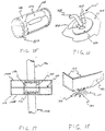
- the hazard control system 100 is configured for a connection point of a fluid line 1612 to a fluid reservoir 1614.
- the hazard control system 100 suitably includes a housing 102 in the form of a ring 1610 or similar shape that covers the attachment point of the fluid line 1612 and reservoir 1614 and attached to the surrounding face of the reservoir 1614.
- the ring 1610 has sufficient internal volume to contain enough control material 104 for a particular hazard, such as a dry chemical suppressant to prevent the ignition of any fluids released by the separation of line 1612 and reservoir 1614, for example due to an accident.
- the present example also suitably includes a washer 1616 attached to the fluid line 1612.
- scored fracture lines 1618 may also be added to the outer faces of the ring 1610. If an event occurs that results in the pulling of the fluid line 1612 sufficiently as to separate it from the reservoir 1614 (such as due to a collision), then the washer 1616 (attached to the fluid line 1612) pulls through the ring 1610, rupturing the ring 1610 and dispersing the control material 104 around the surrounding area to suppress the hazard, such as ignition of fluid discharging from the disconnected line in the local area.
- the hazard control system 100 may be further configured for controlling hazards at the coupling of two fluid lines 1706.
- the housing 102 comprises two disks 1708A-B that are attached to each other, such as by use of an adhesive 1710.
- the outer surfaces of the disks form cavity 1712 to accommodate a coupling 1714 connecting together two fluid lines 1706.
- a flange 1716 may be attached to each fuel line 1706, outside of the coupling 1714 but captured within the disks 1708A-B when they are attached together.
- the outer faces of the disks 1708A-B may also have their surfaces scored radially from their fuel line openings to assist in panel breakup.
- the flange 1716 of either fluid line 1706 pulls through the panel disks 1708A-B and shatters them and the control material 104 is released at the same time to inhibit the relevant hazard, such as the ignition of any fluids discharged from the disconnecting lines.
- the adhesive force between the faces of the disks 1708A-B is designed to be stronger than the force required to fracture either disk 1708A-B by a flange 1716 on either line, to assure that disk fracturing occurs.
- the hazard control system 100 may be adapted for controlling a hazard in the event of damage to an oil pan.
- the hazard control system 100 includes a housing 102 over an oil pan 1810, suitably formed as a tightly fitting housing 102 which has been molded from liquid plastic or formed from double wall material, a rectangular formation of flat doublewall panels in the general shape of the oil pan 1810, or other suitable configuration.
- the housing 102 is attached to the oil pan 1810 by any appropriate mechanism and contains an appropriate control material 104.
- the housing 102 may extend over the lower engine block as well, in the event of engine failure in other areas.
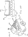
- the housing 102 may also be placed as a sheet or curved panel some distance away from the oil pan 1810, but within proximity of the oil pan 1810 sufficient to assure its rupture from the discharged engine components. If the engine to which the oil pan 1810 is attached breaks a connecting rod 1812 and propels it through the oil pan 1810, discharging oil and fuel, the housing 102 also tends to break and discharge the control material 104, for example as a cloud of fire suppressant to prevent the ignition of the released oil and fuel near the exhaust manifold or other ignition sources.
- the hazard control system 100 may be configured for controlling hazards in an engine compartment.
- the hazard control system 100 is suitably configured to diminish a hazard in the event the engine compartment is damaged or another trigger event occurs.
- the hazard control system 100 may be configured to inhibit fire in the event the engine compartment of a convention automobile is damaged, such as in a front-end collision.
- an exemplary hazard control system 100 includes a housing 102 attached to or integrated into the hood of a car, truck, or other vehicle.
- the hood is configured to bend near their center point in the event of a front-end impact to dissipate energy and to prevent its disconnection at the hinges, which might possibly drive the hood toward the occupants.
- the vehicle hood 1914 is configured to deform as normally designed, forming a crease 1916 along a pre-set failure line.
- the housing 102 comprises a hood liner 1918 containing the control material 104, such as a fire extinguishing chemical, for example a dry chemical powder, and formed to the general shape of the underside of the hood 1914.
- the liner 1918 may have surface coverings to feature sound dampening, or have special sound dampening material added between the liner 1918 and the hood 1914.
- the liner 1918 When the hood 1914 deforms in a collision, the liner 1918 also deforms until it fractures.
- the liner 1918 may also include scored lines formed on the surface of the liner 1918 to assist in the breakup of the liner 1918.
- the control material 104 within the liner 1918 is discharged down onto the engine compartment to prevent any fires or other relevant hazard that might result from the discharge of flammable or otherwise hazardous materials.
- the hazard control system 100 is configured to respond to a thermal trigger event.
- the trigger event may comprise any appropriate thermal trigger event, such as a sudden rise in temperature or a temperature above a selected threshold.
- the thermal event may be generated by a fire 2010 underneath a fluid reservoir, such as a fuel tank 2012.
- the fuel tank 2012 has a housing 102 adjacent or integrated into the tank containing a control material 104.
- the housing 102 may be configured in any suitable manner, such as a series of flat panels containing control material 104 placed on the outer surfaces of the fuel tank 2012, a pre-formed and molded shape that conforms to the outer shape of the fuel tank 2012, or actually molded into the outer surface of the tank 2012 itself.
- the housing 102 when a pool fire 2014 occurs underneath the fuel tank 2012, the housing 102 cracks and breaks up, for example due to the resultant thermal loading, and discharges its contents of control material 104, for example to extinguish or mitigate the pool fire or otherwise control a hazard.
- the housing 102 is configured to crack and fracture upon exposure to thermal stresses above a selected threshold, such as from a pool fire 2014 a few centimetres (inches) from it.
- the housing 102 suitably includes a bottom face sheet facing the ground constrained by a rigid frame on its perimeter.
- the face sheet suitably has a higher thermal rate of expansion than the frame, such that when the housing 102 is exposed to heat above a selected threshold, the frame restrains the thermal expansion of the bottom face sheet, thus causing stress within the panel to cause its cracking and rupture. Stress can be applied via pre-loading the panels in the frame or by other heat treatments such that minimal additional thermal stresses are required to achieve the fracture condition.
- the face sheet may melt, peel back, or otherwise move aside upon exposure to heat above a selected threshold.
- the control material 104 may be configured to swell upon exposure to heat above the selected threshold to cause or supplement the cracking and rupture of the face sheet.
- the face sheet to rupture may be pre-loaded by controlling of the forming and post-heating processes.
- Such techniques may be applied to plastic tanks that are molded and are in abundant use today, but which may be particularly vulnerable to failure when exposed to pool fires established underneath them.
- the hazard control system 100 may also be adapted for use in conjunction with nonflammable hazards, such as an enclosure that houses batteries that may be used on an electric vehicle. If such a container is ruptured, such as due to a collision, and the enclosure is ruptured as well as the batteries, caustic and corrosive battery acids can be released to the environment. Such acids pose a hazard to the vehicle occupants, the environment, rescue personnel, and those hired to inspect the wreckage and transport it to a safe area.
- nonflammable hazards such as an enclosure that houses batteries that may be used on an electric vehicle. If such a container is ruptured, such as due to a collision, and the enclosure is ruptured as well as the batteries, caustic and corrosive battery acids can be released to the environment. Such acids pose a hazard to the vehicle occupants, the environment, rescue personnel, and those hired to inspect the wreckage and transport it to a safe area.
- a hazard control system 100 may be configured for any application where a caustic, corrosive, toxic, or otherwise harmful chemical may be unintentionally released, such as due to a vehicle collision or accident, including tractor-trailers and other transport vehicles that haul such caustic and dangerous chemicals in large quantities.
- the hazard control system 100 may employ a housing 102 covering or adjacent to the single battery used on virtually all vehicles to inhibit excessive damage resulting from a potential leakage or spray of battery acid within the engine compartment, or toward operators if the battery is damaged in a collision or explodes due to other damage to the battery.
- the housing 102 comprises one or more protective panels 2110 adjacent a battery enclosure 2112, such as on the exterior and/or in the interior of the battery enclosure 2112. If the enclosure 2112 is damaged, such as in a collision, the battery enclosure 2112 may rupture 2114 and permit the spillage of acid 2120 from the damaged batteries 2116.
- the protective panels 2110 are also configured to rupture in the event of damage to the enclosure 2112, which facilitates discharge of the control material 104, such as a neutralizing chemical 2118, to control or mitigate the hazard presented by the released acid.
- the neutralizing chemical may be any appropriate material, such as sodium bicarbonate.
- the various components of the hazard control system 100 may be formed according to any appropriate technique or method.
- the housing 102 and the core 112 may be cut, cast, extruded, machined, stamped, molded, or otherwise formed to configure to the desired shapes.
- the housing 102 is suitably vacuum molded, injection molded, or blow molded to form a desired configuration, such as to conform the housing 102 to a particular shape like the exterior of a particular vehicle fuel tank.
- the face sheets 106 are suitably vacuum molded.
- the housing 102 is suitably blow molded.
- a core 112 may be formed, for example by extrusion.
- the compartments, channels 610, or other interior structure of the housing 102 may be generated by forming the interior surface of one or more face sheets 106, for example during the molding of the face sheets 106.
- the face sheets 106 may then be joined to form the housing 102, suitably surrounding the core 112, if desired. If the ends are sealed using end caps, the end caps may be attached, for example after insertion of the control material 104.
- the housing 102 is suitably formed of a plastic or other material that may exhibit a grain, or a tendency to more easily crack or shatter in a particular direction.
- the interior structure of the housing 102 such as the core 112, the channel partitions, rows of compartments, or the like, may be configured to extend perpendicularly to the grain. Because the interior structure may tend to support the integrity of the housing 102, extending the interior structure perpendicular to the grain of the housing 102 material may facilitate easier and/or more extensive shattering of the housing 102. Orienting the grain perpendicular to the channels promotes opening of multiple channels or compartments to discharge more control material, as the cracks tend to propagate along the grain across multiple channels or compartments.
- the control material 104 may be added in any suitable manner, such as before joining the housing 102 components or after assembly of the housing 102.
- the control material 104 may be added by standing the housing 102 upright and resting on one end and pouring the control material 104 into the upper end of the housing 102.
- the control material 104 may be added to the individual compartments or channels 610 in any other appropriate manner, such as by inserting the control material 104 directly into each channel or compartment.
- the control material 104 can be poured, injected under pressure, or otherwise inserted into the channels 610.
- the access openings for adding the control material 104 are then suitably closed. If the housing 102 uses end caps, the end cap 810 can be snapped into position, substantially sealing the housing 102. Any other relevant system for maintaining the control material 104 within the housing 102 may be implemented, such as sealing the openings with caulk, putty, plugs, membranes, tape, or other mechanism.
- the hazard control system 100 may then be attached to the relevant hazard source.
Landscapes
- Business, Economics & Management (AREA)
- Emergency Management (AREA)
- Health & Medical Sciences (AREA)
- Public Health (AREA)
- Chemical & Material Sciences (AREA)
- Chemical Kinetics & Catalysis (AREA)
- General Chemical & Material Sciences (AREA)
- Cooling, Air Intake And Gas Exhaust, And Fuel Tank Arrangements In Propulsion Units (AREA)
- Fire-Extinguishing By Fire Departments, And Fire-Extinguishing Equipment And Control Thereof (AREA)
- Fire-Extinguishing Compositions (AREA)
- Blow-Moulding Or Thermoforming Of Plastics Or The Like (AREA)
Description
- The invention relates to methods and apparatus for controlling hazardous and/or flammable materials and the effects of such materials.
- Flammable and otherwise hazardous materials play an important role in the everyday lives of most people. Most people encounter flammable materials, such as gasoline, engine oil, and natural gas, and other hazardous materials, such as battery acid and concentrated detergents, without danger. Because the unsafe materials are contained, they typically present no problem for those that are nearby.
- When the unsafe materials become uncontained, however, the materials can injure or kill, such as when the container is damaged and the material escapes. For example, hundreds of thousands of vehicular accidents occur each year on American highways. Many accident-related fire events occur when the region of the vehicle containing the fuel tank is impacted in an accident, spilling the fuel contents from the tank in the form of a spray, stream, and eventual pool around the vehicle. The highly ignitable spray mist generated upon impact may be exposed to ignition energy from sparks generated from vehicle deformation on impact for only a fraction of a second. This duration, however, may be long enough to ignite the fuel mist into a possible explosion, or more likely a fireball that ignites a developing pool of fuel surrounding the vehicle and create a more serious threat.
- In many cases, the threat of ignition and resultant flame spread only exists for the instant that the sparks from the impact event remain. These events have been noted particularly on several recent automotive and truck designs that were hypothesized, due to tank placement and structural design, to have potentially higher rates of incidences of such events. These high profile examples often lead to spectacular fire events and the higher rates of burn injuries and fatalities when they occur, and have resulted in national discussions on how to prevent their continued occurrence.
- Unfortunately, most fire protection technologies are impractical for general highway vehicle or other consumer use, due to cost, complexity, reliability problems, and substantial weight increases. As a result, little has been done to prevent such events in the future. The military, however, has confronted similar events that occur in combat scenarios. In particular, military aircraft that are impacted by anti-aircraft projectiles can develop fires in adjoining bays adjacent to fuel tanks onboard the aircraft. The fuel leaking or spraying from a penetrated tank encounters ignition sources, such as burning incendiary particles deposited by the projectile in the adjoining bay, with resultant fires threatening the interior of the aircraft. Many aircraft losses in combat have been attributed to such events.
- As a result, technologies have been developed in recent decades to prevent or suppress such events for newer combat aircraft. One approach to aircraft fire protection uses passive systems. These systems are typically some form of structure that requires no electrical power or other artificial monitoring. These systems function by being impinged directly by the explosion or fire event. They typically provide explosion protection inside the fuel tank or in surrounding compartments around the fuel tank. One of the earliest and most successful variants was the use of flexible reticulated foam in fuel tanks to mitigate explosions. This concept was extensively used successfully in the latter stages of the Vietnam War and became a fixture on many modern era aircraft.
- The British military developed several advanced concepts in the early 1970s. These included forming reticulated foam into balls to fill various compartments adjacent to fuel tanks in aircraft (U.K. Patents
1,380,420 1,445,832 1,454,492 - Other passive protection systems use fire suppressants embedded into rigid or semi-rigid panels mounted onto the wall of the fuel tank adjoining and facing an adjacent bay. The panels, when impacted by a projectile penetrating through the aircraft, would rupture locally and release a portion of suppressant into the adjacent bay, extinguishing the beginnings of fuel spray from the damaged fuel tank entering the bay and igniting, or rendering the fuel vapors inert against ignition when coming into contact with the deposited incendiary particles. The panels were developed and demonstrated with gaseous extinguishing agents and various powders (U.K. Patents
1,454,493 1,547,568 - All of these variations showed some level of performance enhancement for a given system volume or weight, but could be offset by increased complexity or increased material, assembly, or installation cost. The most common and simple variations were thin panels with a hexagonal honeycomb sandwich material of kraft paper, aluminum, or Nomex, filled with a fire extinguishing powder and covered with a thin sheet on both faces of aluminum foil, composite fibers, or other materials. These devices were described as powder panels or powder packs.
- The powder panels were demonstrated to effectively protect against many large ballistic incendiary threats with as little as about 0.254cm (0.1 inch) total thickness and about 0.01-0.03 kg mass per square metre (0.2-0.6 pounds mass per square foot). Other threats and conditions could require much thicker, heavier, systems if they worked at all. Some limitations in performance were seen against small threats that limited rupture damage to the panel and as a result limited the amount of powder suppressant released to extinguish the fire.
- Variations of this concept were investigated for use against ballistic impacts in armored vehicles (
U.S. Patent Nos. 3,930,541 and4,132,271 ), although powders were primarily limited for use in engine compartments due to the inhalation difficulties with crew members, and gaseous suppressant filled panels were used in the crew compartment. Later fine tuning was made including adding spall shields to prevent spallation damage from the panels to crew members. - Since these systems require ballistic impact to function, their utility and consideration was limited to combat-induced ballistic impact events; they offer no protection against gradual fuel system leakage and ignition due to ordinary fuel system failures. Further, such systems do not provide protection against other types of threats or problems. For example, such systems do not provide protection in other fire scenarios, such as collisions impacting and fracturing fuel tank valves and their connectors, particularly for alternate fueled vehicles. Additional flammable fluid reservoirs, such as brake master cylinders and fuel pumps, contain sufficient flammable fluid to pose a threat to vehicle occupants or the vehicle itself, and their small, bulky shapes provide difficulties in providing protection. Other areas of a vehicle, such as the vehicle's engine compartment hood, exhibit damage in front end crashes, and may cause the release of flammable or otherwise hazardous materials. Further, some components, such as the oil pan, may rupture and discharge flammable fluids due to the internal destruction of the engine, which is typically accompanied by the fracturing and penetration of the connecting rods through the oil pan. This scenario is very common in automobile racing in addition to highway occurrences.
-
US 4251579 describes a fire protection panel consisting of an array of cells, sandwiched between two flat facing sheets and containing a fire extinguishant. The cells are arranged in a honeycomb or lattice layout, with each cell sharing an adjoining wall with one of its neighbouring cells. The shared walls are permeable and/or have small notches in them to permit permeation of the extinguishant through the cells.US 5575339 teaches an expandable metal foil or net which is used in extinguishing surfaces fires.GB2255015A US20020020536A1 discloses various configurations and applications for a thin, breakable panel containing a dry chemical fire extinguishant, typically for use in transportation systems. -
US 3804292 discloses a fire-preventing fuel tank in which adjacent but separate volumes are provided inside the tank, one kind of volumes holding the fuel, whereas the other holds a substance (e.g. a halogen), which when admixed to the fuel, makes it non-flammable. - The scope of protection is defined by the independent claims, to which reference should now be made. Advantageous features are set out in the dependent claims.
- According to one aspect of the present invention, there is provided a hazard control system comprising a fuel tank, a control material and a housing, the housing being attached to or abutting an outer surface of the fuel tank. The housing is configured to deliver the control material in response to a trigger event. The housing has multiple rows of interconnected compartments containing the control material. The compartments have openings connected by ducts to allow flow of the control material between the interconnected compartments. The housing comprises two face sheets, at least one of the face sheets including multiple indentations. The two face sheets are joined so that one of the face sheets covers the indentations in the other face sheet to form the compartments and the ducts. The rows of interconnected compartments are parallel to a longitudinal axis of the face sheets.
- According to another aspect of the present invention, there is provided a method of controlling a hazard from a fuel tank. The method comprises: providing a hazard control system by mounting a housing to an outer surface of the fuel tank, wherein the housing defines multiple interconnected compartments, the compartments having openings connected by ducts to allow flow of control material between the interconnected compartments; and disposing a control material in the housing. The housing comprises two face sheets, at least one of the face sheets including multiple indentations, the two face sheets joined so that one of the face sheets covers the indentations in the other face sheet to form the compartments and the ducts. The rows of interconnected compartments are parallel to a longitudinal axis of the face sheets.
- A hazard control system disclosed herein comprises a housing configured to contain a control material and deliver the control material to neutralize a hazard in response to a trigger event. In one embodiment, the control material is an extinguishant for retarding fire. The housing contains the extinguishant and includes at least one surface configured to rupture in response to a trigger event, such as an impact. The housing may also include a surface configured to substantially mate with a surface of a vehicle, such as a fuel tank surface.
- A more complete understanding of the present invention may be derived by referring to the detailed description when considered in connection with the following illustrative figures. In the following figures, like reference numbers refer to similar elements and steps.
-
Figure 1 is an illustration of a prior art hazard control system having a honeycomb core; -
Figure 2 is a cross-section view of the prior art hazard control system ofFigure 1 ; -
Figure 3 is an illustration of a prior art housing configured for a fuel tank. -
Figure 4 is an illustration of a prior art hazard control system having multiple panels around a fuel tank. -
Figure 5 is an illustration of a crash incident involving impact between two motor vehicles, one of which is equipped with a prior art hazard control system; -
Figure 6 is a partial cutaway view of a prior art hazard control system having multiple parallel, isolated channels; -
Figure 7 is a cross-section view of the prior art hazard control system ofFigure 6 ; -
Figure 8 is an illustration of a prior art end cap; -
Figure 9 is an illustration of a prior art hazard control system having shattering a face sheet; -
Figure 10A-B are top and cross-section views, respectively, of a hazard control system having multiple perpendicular, interconnected channels; -
Figure 11 is a cross-section view of a prior art hazard control system having partitions integrated into a face sheet and bonded to another face sheet by an adhesive; -
Figure 12 is an illustration of a hazard control system having multiple interconnected compartments; -
Figures 13A-B are perspective and top illustrations, respectively, of a hazard control system conformed to the shape of a fuel tank; -
Figures 14A-C are illustrations of a hazard control system being cut to a desired size; -
Figure 15 is a partial cutaway view of a fuel pump shrouded with a prior art hazard control system; -
Figure 16 is a view of a fluid reservoir fitting surrounded by a prior art hazard control system at the location of connection of the reservoir to the fluid line; -
Figure 17 is a view of a prior art hazard control system fitted for a connector of two fluid line fittings; -
Figure 18 is an illustration of a prior art hazard control system adapted for an oil pan of an internal combustion engine pierced by a connecting rod; -
Figure 19 is an illustration of a vehicle front-end collision, with the engine compartment hood deforming and activating the prior art hazard control system; -
Figure 20 is a cross-section view of a liquid reservoir having a prior art hazard control system and a pool fire impinging on a liquid reservoir; and -
Figure 21 is a cross-section view of a damaged battery enclosure having a prior art activated hazard control system. - Elements and steps in the figures are illustrated for simplicity and clarity and have not necessarily been rendered according to any particular sequence. For example, steps that may be performed concurrently or in different order are illustrated in the figures to help to improve understanding of embodiments of the present invention.
- The present invention is described partly in terms of functional components and various processing steps. Such functional components may be realized by any number of components configured to perform the specified functions and achieve the various results. For example, the present invention may employ various elements, materials, suppressants, neutralizing agents, and the like, which may carry out a variety of functions. In addition, the present invention may be practiced in conjunction with any number of applications, environments, hazardous materials, and trigger events, and the systems described are merely exemplary applications for the invention. Further, the present invention may employ any number of conventional techniques for manufacturing, assembling, mounting, and the like.
- Referring now to prior art
Figures 1 and 2 , ahazard control system 100 for controlling hazardous and/or flammable materials may be implemented in conjunction with ahousing 102 containing acontrol material 104. Thehousing 102 is configured to contain thecontrol material 104 and facilitate dispersal of thecontrol material 104 in response to a trigger event, especially relatively large quantities ofcontrol material 104 for relatively large-scale events such as an impact, exposure to heat, or detection of a hazard. Thecontrol material 104 comprises one or more materials for controlling a hazard. - The
housing 102 may comprise any suitable apparatus for containing thecontrol material 104 and facilitating dispersal of thecontrol material 104 in response to the trigger event. For example, thehousing 102 may comprise a container configured to shatter, explode, or otherwise deteriorate, either entirely or in part, upon impact to release thecontrol material 104. Thehousing 102 may comprise a rigid structure, a semi-rigid structure, a membrane, or a bladder. Thehousing 102 may be comprised of any suitable materials, for example glass, ceramic, or plastic that is designed to shatter upon impact. Further, thehousing 102 may be configured to promote dispersal of thecontrol material 104, for example by scoring thehousing 102 to promote fracturing of the scored surface in the event of an impact. Thehousing 102 may include additional mechanisms for promoting dispersal of thecontrol material 104, such as one or more spring mechanisms, such as a leaf spring, compressed coil spring, a flat spring, an expandable material, configured to enhance the expansion of thehousing 102 when thehousing 102 is weakened or fractured by the trigger event. In one example, multiple channels formed in thehousing 102 include spring mechanisms to biased against a surface of thehousing 102 to be impacted. - In the present example, the
housing 102 suitably comprises twoface sheets 106 sandwiching thecontrol material 104. Theface sheets 106 maintain thecontrol material 104 in position, and may comprise any suitable configuration, such as a rigid sheet, a flexible cover, a flexible bladder, or any other appropriate system for maintaining thecontrol material 104 in a selected position. Further, theface sheets 106 may comprise any appropriate materials, including cellulosic material such as styrene, paper, glass, plastic, metal, ceramic, aluminum, nylon, glass fabric, fiberglass/epoxy, Kevlar, graphite tape, or a composite or combination of such materials. Theface sheets 106 are suitably configured to react to a trigger event, such as an impact, a thermal event such as exposure to heat, or an optical event such as exposure to particular radiation. In the present example, theface sheets 106 are suitably configured to substantially completely shatter or otherwise rupture to promote total release of thecontrol material 104. Thehousing 102 may also comprise malleable materials, so thehousing 102 may be shaped and bent to fit various configurations. In the present example, theface sheets 106 are rectangular sheets constructed of a lightweight and cost effective material, such as glass, ceramic, acrylic, and/or epoxy. - The
face sheets 106 are suitably mounted on aframe 108 to support theface sheets 106. Theframe 108 may comprise any suitable structure, such as a rigid structure joined to theface sheets 106, an adhesive material like a caulk between theface sheets 106, or a rigid spacer. In an alternative example, theframe 108 may be omitted and theface sheets 106 may be otherwise configured to maintain the position of thecontrol material 104. For example, the ends of theface sheets 106 may be taped adhesively, glued, or crimped, or the face sheets may be formed as a single unit, such as using blow molding, vacuum forming, or thermoforming to form thehousing 102. - In the present example, the
frame 108 is configured to support theface sheets 106 and maintain thecontrol material 104 in position. For example, theframe 108 suitably comprises a rigid structure having the same shape as theface sheets 106 and bonded to theface sheets 106. Thus, in the present example, theframe 108 comprises a rigidrectangular frame 108 configured to support theface sheets 106. In addition, theface sheets 106 may be connected to theframe 108 in any suitable manner, for example using fasteners or a bonding agent. In the present example, theface sheets 106 are bonded using an epoxy 110 or a similar adhesive. Other variations may be used to bond theface sheets 106 to theframe 108, such as hot glues and other chemical adhesives. - The
housing 102 may also include acore 112 configured to separate thecontrol material 104 into multiple compartments. Thecore 112 may also maintain a desired space between theface sheets 106 and support theface sheets 106. Thecore 112 may be configured in any suitable manner. In the present example, thecore 112 may be configured in a honeycomb configuration to form individual compartments. In addition, thecore 112 may comprise any appropriate materials, such as lightweight, rigid materials. In the present example, thecore 112 comprises aluminum or Nomex. - The
housing 102 contains thecontrol material 104. In the present example, thecontrol material 104 is contained in the compartments formed by thecore 112. Thecontrol material 104 may comprise one or more suitable materials for neutralizing a particular hazard, such as a fire, acid spill, or noxious gas release. For example, to extinguish a fire, thecontrol material 104 may comprise a fire suppressant, such as monoammonium phosphate, mixed with an appropriate desiccant and/or flow enhancer such as a 1% concentration of micronized fumed silica. Alternatively, the suppressant may comprise sodium bicarbonate, potassium bicarbonate, potassium carbonate, urea-based powders, potassium dawsonite, ammonium polyphosphate, monoammonium phosphate, potassium iodide, or other powder suppressants or mixtures, or liquid or gaseous agents, such as water, nitrogen, carbon dioxide, argon, iodotrifluoromethane, heptafluoropropane, pentafluoroethane, or other gaseous agents or mixtures. - The compartments of the
core 112 are suitably totally filled to capacity, though some settling may occur after construction and installation, leaving some void space in thecore 112. If the compartments are not completely full, thecontrol material 104 may be supplemented with a filler, such as a neutral, non-burning substance to occupy internal volume. In the present example, the filler is configured to cover a large area while adding little weight. The filler may comprise, for example, silica dessicant, glass or plastic microspheres which may be filled with thecontrol material 104 or remain empty, or other suitable lightweight material. - In addition, the
control material 104 may be enhanced to facilitate dispersal and/or react to the trigger event. For example, the control material may be pressurized, for example with air, agaseous control material 104, or other fluid to enhance dispersal of thecontrol material 104. Further, thecontrol material 104 may respond directly to the trigger event. For example, thecontrol material 104 may include an optically reactive, thermally reactive, or impact reactive material that causes thecontrol material 104 to expand or otherwise deploy. - The
control material 104 may also be supplemented with or include a propellant to propel thecontrol material 104 out of thehousing 102 to enhance delivery. For example, thecontrol material 104 may be supplemented containers of gas, such as ambient or pressurized air or a fire suppressant gas, that when compressed by the impact, burst and provide a gust of air to help disperse the control material 14. The containers may comprise any suitable containers, such as enclosed tubes or balls of thin plastic or other suitable material. Alternatively, the propellant may comprise a material that, when exposed to air, generates an expanding volume of gas to propel thecontrol material 104. The propellant may also comprise a fire suppressant material, such as carbon dioxide. Alternatively, the propellant may include different areas of thehousing 102 that may contain separate materials. When the materials react to the trigger event, such as in response to heat or by mixing following rupture of thehousing 102, the materials may react to generate a propelling gas and, in some embodiments, a supplemental fire suppressant. For example, the materials may comprise acetic acid and a sodiumbicarbonate control material 104, which produces carbon dioxide when mixed. Alternatively, the material may comprise carbonic acid, which reacts to heat, such as due to a fire, by decomposing to water and carbon dioxide. Other materials may be used that create carbon dioxide and water when mixed, such as calcium carbonate and hydrochloric acid, or sodium carbonate and dilute sulfuric acid. Yet other materials may produce a fire suppressant foaming agent. For example, the supplementary material orcontrol material 104 may comprise sodium bicarbonate powder with a licorice additive, which mixed with aluminum sulfate will make a sticky, aluminum hydroxide foam. Other materials may comprise compositions of nitrogen triiodide or nitrogen tribromide powders or solids, possibly mixed with stabilizing binders, which when impacted convert to nitrogen gas and fire suppressing iodine or bromine gas. - The
hazard control system 100 may be attached to a hazard source, such as a fuel tank or other hazardous material storage unit in a vehicle, such as a car, bus, truck, aircraft, racing car, police car or van, military vehicle or craft, racing boat, rail car, tractor trailer, or heavy equipment. For example, referring to prior artFigures 5 and9 , ahighway vehicle 510 is suitably equipped with thehazard control system 100 by attaching thehazard control system 100 to the vehicle'sfuel tank 514. When thehighway vehicle 510 is impacted by a colliding vehicle 512, the exterior of thehighway vehicle 510 and thefuel tank 514 deform, also deforminghazard control system 100 attached to thefuel tank 514. When deformed and ruptured, thehazard control system 100 releases thecontrol material 104, such as a suppressant powder 516 comprising monoammonium phosphate, which tends to neutralize the area around the damaged and potentially leakingfuel tank 514 to inhibit fire initiation. Thehazard control system 100 may be configured for any suitable environment or application, however, such walls that may be subject to impact, heat, or other hazard, exterior of buildings, near airport runways, within or upon hazardous material transports, and the like. - The
hazard control system 100 may be configured in any suitable manner for a particular application, such as to enhance or direct dispersal of thecontrol material 104, facilitate adaptation to multiple applications, reduce weight and/or cost, fit to particular objects, mitigate one or more different hazards, and the like. Referring to prior artFigures 6 and7 , analternative housing 102 includesmultiple channels 610. Thechannels 610 are suitably configured to contain thecontrol material 104 for release. Thechannels 610 may be configured in any suitable manner and formed by any appropriate structure. For example, thechannels 610 may be formed by thecore 112 or on one or more of theface sheets 106, theframe 108, and/or other parts of thehousing 102. - In the present example, the
channels 610 are formed by raised partitions formed on an interior surface of at least one of theface sheets 106. Consequently, nocore 112 is included. Alternatively, thehousing 102 may include thecore 112 to form thechannels 610, and theframe 108 may also include structure, such as protruding partitions or other suitable structure, to form all or part of thechannels 610. In addition, thechannels 610 may be formed in any appropriate manner to maintain the position of thecontrol material 104, facilitate dispersal of thecontrol material 104 upon occurrence of the trigger event, provide ease of manufacturing and/or installation, or any other purpose. In the present example, thechannels 610 are configured to form individualparallel channels 610. Alternatively, thechannels 610 may be configured in a serpentine pattern,diagonal channels 610, a combination of diagonal, horizontal, vertical, and/or otherwise orientedchannels 610. - Further, the
channels 610 may run in any suitable direction, and may be interconnected. For example, referring toFigures 10A-B , thechannels 610 may run horizontally and vertically through thehousing 102. Thechannels 610 are defined bypartitions 1010. Thepartitions 1010 may also maintain separation between theface sheets 106, and may also provide attachment points for connecting the twoface sheets 106 together, for example using an adhesive, to form thehousing 102. Thepartitions 1010 may comprise any appropriate configuration, such as square, circular, or rectangular partitions, and may be formed in any suitable manner, such as by collectively forming aseparate core 112 or by being formed on or attached to one ormore face sheets 106. Such partitions may also be included in configurations using individual channels or compartments, such as channels or compartments that are hermetically sealed from one another, for example to provide additional rigidity. - The
housing 102 may also include structural components to provide rigidity, such as ribs formed in the housing. In addition, theface sheets 106 may be joined by an adhesive 1114 that has limited bond strength, sufficient only for normal operational environments. The limited strength of the adhesive suitably provides minimal impedance to crack propagation of thesecond face sheet 1112, facilitating separation of the second face sheet 1112 (in its entirety or in pieces) from thepartitions 1010. - To enclose the
housing 102, thehousing 102 edges may be sealed, for example using tape or caulk. Referring toFigures 6 and8 , thehousing 102 of the present example is closed along anedge 610 with anend cap 810. Theend cap 810 may be connected to theface sheets 106 in any suitable manner, for example by being snapped, glued, adhered, fastened, or otherwise attached to theedge 610. Theend cap 810 may comprise any suitable material, such as rubber or other resilient material, to be pressed into theedge 610 of thehousing 102. - The
housing 102 may include any appropriate materials to facilitate response to the trigger event, provide manufacturing efficiency, reduce weight, or satisfy any other appropriate criteria. For example, referring to prior artFigure 11 , thehousing 102 may be configured to aid in its full discharge of extinguishing chemical in response to a trigger event including an impact. To facilitate greater breakup of thehousing 102 upon impact, first face sheet 1110 andpartitions 1010 may be formed of a first material that is relatively inexpensive and strong, such as in one piece of polycarbonate, and thesecond face sheet 1112 may comprise a material more prone to total breakage when impacted, such as acrylic or styrene. Alternatively, thehousing 102 may be completely formed of a single material, such as acrylic, styrene, styrenics polymer, polyphenylene, polypropylene, and/or polycarbonate. In the present example, the housing comprises a material having desired brittleness and durability and demonstrating favorable fabrication features, such as a plastic, alloy, ceramic, composite, metal, fiber, and/or glass. The particular material and configuration may be selected according to the particular application. In one example, the housing material may be treated to improve the various characteristics of the housing material. For example, the housing may comprise a first material having desirable brittleness, such as acrylic, styrene, styrenics polymer, or the like, and a second polymer, such as a fiber, polycarbonate, or another type of acrylic, styrene, styrenics polymer, or the like, configured to improve the characteristics of the first material, such as the ductility to improve the workability of the material. For example, the housing material may comprise a first styrenics polymer having a high brittleness and a second styrenics polymer mixed with the first to lower the melting temperature of the overall housing material and otherwise improve the manufacturing characteristics of the material. The ratio of the first material to the second material may be selected according to the desired characteristics of the housing. For a high brittleness material, the second material may comprise only a small amount, such as about 10% by weight or less, of the overall material. For improved ductility during manufacturing, the second material may comprise a larger amount, such as about 50% or more of the overall material. In one example, the first brittle material comprises about 60-80% of the overall material, and the second material comprises about 20-40% of the overall material. A suitable material may comprise approximately 70% of the first material and about 30% of the second material. - According to an embodiment of the claimed invention, the
housing 102 includes multiple compartments for containing thecontrol material 104. Each compartment is connected to one or more other compartments. For example, each compartment may be individually filled with thecontrol material 104. Alternatively, a compartment may be connected to another compartment so that both compartments may be filled by accessing a single compartment. Using multiple compartments suitably facilitates cutting thehousing 102 to a selected size. - For example, referring now to
Figure 12 , thehousing 102 includesmultiple compartments 1210 containing thecontrol material 104. Thecompartments 1210 may have any appropriate shape or size, such as approximately 7.62 cm (three inch) by 12.7 cm (five inch) rectangles. Thehousing 102 may form thecompartments 1210 in any suitable manner. In addition, the compartments may be oriented in any manner, such as in rows parallel to an axis of thehousing 102 or one or more of theface sheets 106. - In the present embodiment, the
housing 102 comprises two face sheets 106AB. At least one of theface sheets 106A includes multiple indentations to form thecompartments 1210. For example, the second face sheet 106B may be flat and thefirst face sheet 106A may be configured to include multiple indentations in the form of thecompartments 1210. The compartments are suitably formed in rows parallel to a longitudinal axis of theface sheets 106. - The two
face sheets 106 are joined in any suitable manner so that the second face sheet 106B covers the indentations in thefirst face sheet 106A to form thecompartments 1210. Thecompartments 1210 may, however, be formed in any suitable manner, such as by indentations in the second face sheet 103B, compartments formed by thecore 112, independent bladders, a quilted bladder having multiple pockets, and the like. - The
compartments 1210 of the present embodiment are suitably connected to allowcontrol material 104 to flow between theinterconnected compartments 1210. Thecompartments 1210 may be interconnected in any suitable manner, such as viaopenings 1212 formed along one or more sides or other surfaces of thecompartments 1210. Further, theopenings 1212 are connected via one ormore ducts 1214 connecting theopenings 1212. The connections between thecompartments 1210 may be implemented in any appropriate manner, such as using tubes attached to thecompartments 1210, indentations in one or both of theface sheets 106, inclusion of a core 112 including theducts 1214, and the like. In the present embodiment, theducts 1214 are formed by indentations formed in thefirst face sheet 106A adjacent the indentations used to form thecompartments 1210. - In addition, the
housing 102 may include any other desired structures to lend desired characteristics to thehousing 102, such as to add stiffness, provide mounting surfaces or mechanisms, and the like. For example, in the present embodiment, thefirst face sheet 106A may includerectangular indentations 1216 formed between theduct indentations 1214 to reduce the surface-to-surface contact between theface sheets 106 and promote crack propagation. - In the present embodiment, each
compartment 1210 along two edges of thehousing 102 has at least oneopening 1212 in one side which is connected to aduct 1214. Eachcompartment 1210 in the interior of thehousing 102 and along the other two edges of thehousing 102 has twoopenings 1212 on opposite sides of thecompartment 1210. Theopenings 1212 are connected to theopenings 1212 of theother compartments 1210 via theducts 1214. Consequently, thecontrol material 104 may move between thecompartments 1210 through theopenings 1212 andducts 1214. - The
hazard control system 100 may be configured for a selected environment, a selected hazard, and/or a selected trigger event. For example, thehazard control system 100 may be adapted for use with vehicle fuel tanks, storage tanks, fuel or chemical transfer lines, connectors, valves, and other components, oil containers and oil pans, battery compartments, engine compartments, or other applications. In addition, thehazard control system 100 may be configured to control flammable materials, toxic materials, caustic or corrosive materials, or other harmful materials. Further, thehazard control system 100 may be configured to respond to any suitable trigger event, such as an impact, exposure to heat, exposure to a particular substance, or detection of a hazardous condition. - For example, the
hazard control system 100 may be specifically configured for particular applications by shaping thehousing 102 to conform to a selected surface. For example, referring toFigure 3 , anexemplary housing 102 substantially conforms to the exterior of the fuel tank. Clearance holes 310 accommodate fittings and exterior connections to the fuel tank. Grommets may also be installed in the clearance holes 310. - Referring to
Figures 13A-B , in one embodiment thehousing 102 may be configured to conform to the exterior shape of afuel tank 1310 for police vehicle, such as a Ford Crown Victoria Police Interceptor, a bus, or a motorsports car. In the present embodiment, thefirst face sheet 106A has an outer surface that is configured to substantially mate with an exterior surface of therelevant fuel tank 1310, such as the top, rear, front, or side of thefuel tank 1310. The outer surface of the second face sheet 106B is configured to conform to the space requirements of the vehicle, such as to fit within the trunk of the vehicle. - The
housing 102 may be configured in any suitable manner to contain thecontrol material 104, such as a fire suppressant, and shatter upon impact to release thecontrol material 104. In the present embodiment, thehousing 102 includes partitions formed in at least one of theface sheets 106 to form the compartments and suitably the ducts to interconnect the compartments as shown inFigure 12 . Theface sheets 106 are suitably bonded together using an adhesive. - Referring to prior art
Figure 4 , an alternativehazard control system 100 comprisesmultiple housings 102. Eachhousing 102 conforms to the respective outer surfaces of thefuel tank 514, and may be attached to thefuel tank 514 in any suitable manner, such as via an adhesive. Alternatively, thehazard control system 100 may comprise a single structure or multiple interconnected structures surrounding the exterior of thefuel tank 514. - In an alternative example, the
hazard control system 100 may be configured for adaptation to any particular application using one ofmore housings 102. For example,multiple housings 102 may be attached to afuel tank 514 or other structure to facilitate hazard mitigation. In addition, thehousings 102 may be cut to a selected size and/or shape for a particular application. - For example, referring again to
Figure 12 , thehousing 102 may be cut to an approximate desired width and length. Anycompartments 1210 that are opened due to the cutting may be emptied ofcontrol material 104. Referring toFigures 14A-C , ahousing 102 is configured to be cut to a desired width 1412 and length 1410. To cut the width, the bottom portion may be cut away (Figure 14B ). Although the cutting opens a series of compartments, several other compartments remain intact. Thus, thehazard control system 100 remains functional. - To cut the length, a length of the
housing 102 may be cut away (Figure 14C ). By cutting the length, multiple compartments may be opened, which may remain empty. The ducts leading to the empty compartments may then be closed, for example using putty, tape, caulk, epoxy, a resilient plug, or other mechanism. Thus, thecontrol material 104 remains within several compartments of thehousing 102. In the present embodiment, the compartment spacings are configured to permit cutting between the cells, to leave a sealing flange, such that only fill ports connecting the cells in each row remain exposed for filling. Consequently, thehousing 102 may be cut after being filled with thecontrol material 104 to reduce unfilled panel material around the perimeter. - The
hazard control system 100 may be attached to or associated with a hazard source in any appropriate manner. In various applications, thehazard control system 100 may be placed adjacent to or above the hazard source. Alternatively, thehazard control system 100 may be attached to or abut the hazard source. Any appropriate system or mechanism may fix thehazard control system 100 in position. For example, thehousing 102 may be adhesively attached directly to thefuel tank 514, such as via a peel-and-stick adhesive tape. Thehousing 102 may be attached by any other suitable mechanism, such as tape, straps, rivets, clips, hook-and-loop fasteners, or other fasteners. - In another embodiment, the
hazard control system 100 may be adapted for a particular component that may be susceptible to causing a hazard. For example, referring to prior artFigure 15 , thehousing 102 is adapted to conform to afuel pump 1510, such as for an internal combustion engine. Thehousing 102 is suitably configured to fit over thefuel pump 1510, such as by vacuum forming, blow molding, or other suitable process. Thehousing 102 may be connected to thefuel pump 1510, such as via a press fit, outer band clamps, or internal adhesive. Thehazard control system 100 may also include aseparate end plate 1512 that is attached (adhesively or otherwise) to the end of thehousing 102 near the outer end of thefuel pump 1510, particularly if simple cylindrical geometries are applicable. Thehousing 102 may be configured according to any appropriate design to facilitate dispersal of thecontrol material 104 in response to the trigger event. In one example, thehousing 102 is configured withchannels 610 between thin double-walledplastic face sheets 106. Thecontrol material 104 is disposed within thechannels 610 orcompartments 1210 of thehousing 102. - The
housing 102 is suitably configured such that when thefuel pump 1510 is impacted sufficiently (such as in an accident) to break off or partially disconnect thefuel pump 1510 from the engine, facilitating the discharge of its flammable fluid contents and its subsequent ignition, thehousing 102 should also break apart due to the same impact, releasing a cloud of suppressant around the region of fluid discharge to mitigate ignition and any resultant fires. Thehazard control system 100 may be similarly adapted for other reservoirs and components, including superchargers and turbochargers, power steering pumps, vapor canisters, brake master cylinders, oil pumps, washer fluid reservoirs, fuel pressure reduction valves, and other valves attached to fluid vessels such as those on compressed natural gas (CNG) tanks, liquefied petroleum gas tanks (LPG), hydrogen tanks, and other alternate fueled vehicles. - The
hazard control system 100 may also be adapted to fluid lines and connectors to control hazards in the event of the trigger event. For example, referring toFigure 16 , thehazard control system 100 is configured for a connection point of afluid line 1612 to afluid reservoir 1614. Thehazard control system 100 suitably includes ahousing 102 in the form of a ring 1610 or similar shape that covers the attachment point of thefluid line 1612 andreservoir 1614 and attached to the surrounding face of thereservoir 1614. The ring 1610 has sufficient internal volume to containenough control material 104 for a particular hazard, such as a dry chemical suppressant to prevent the ignition of any fluids released by the separation ofline 1612 andreservoir 1614, for example due to an accident. - The present example also suitably includes a
washer 1616 attached to thefluid line 1612. In addition, scoredfracture lines 1618 may also be added to the outer faces of the ring 1610. If an event occurs that results in the pulling of thefluid line 1612 sufficiently as to separate it from the reservoir 1614 (such as due to a collision), then the washer 1616 (attached to the fluid line 1612) pulls through the ring 1610, rupturing the ring 1610 and dispersing thecontrol material 104 around the surrounding area to suppress the hazard, such as ignition of fluid discharging from the disconnected line in the local area. - The
hazard control system 100 may be further configured for controlling hazards at the coupling of two fluid lines 1706. For example, referring to prior artFigure 17 , thehousing 102 comprises two disks 1708A-B that are attached to each other, such as by use of an adhesive 1710. The outer surfaces of thedisks form cavity 1712 to accommodate acoupling 1714 connecting together two fluid lines 1706. Aflange 1716 may be attached to each fuel line 1706, outside of thecoupling 1714 but captured within the disks 1708A-B when they are attached together. The outer faces of the disks 1708A-B may also have their surfaces scored radially from their fuel line openings to assist in panel breakup. - If the two ends of the fluid line 1706 are pulled apart (such as due to a collision) and disconnect at the site of the
coupling 1714, theflange 1716 of either fluid line 1706 (or both) pulls through the panel disks 1708A-B and shatters them and thecontrol material 104 is released at the same time to inhibit the relevant hazard, such as the ignition of any fluids discharged from the disconnecting lines. The adhesive force between the faces of the disks 1708A-B is designed to be stronger than the force required to fracture either disk 1708A-B by aflange 1716 on either line, to assure that disk fracturing occurs. - In another alternative example, the
hazard control system 100 may be adapted for controlling a hazard in the event of damage to an oil pan. Referring to prior artFigure 18 , thehazard control system 100 includes ahousing 102 over an oil pan 1810, suitably formed as a tightlyfitting housing 102 which has been molded from liquid plastic or formed from double wall material, a rectangular formation of flat doublewall panels in the general shape of the oil pan 1810, or other suitable configuration. Thehousing 102 is attached to the oil pan 1810 by any appropriate mechanism and contains anappropriate control material 104. Thehousing 102 may extend over the lower engine block as well, in the event of engine failure in other areas. Thehousing 102 may also be placed as a sheet or curved panel some distance away from the oil pan 1810, but within proximity of the oil pan 1810 sufficient to assure its rupture from the discharged engine components. If the engine to which the oil pan 1810 is attached breaks a connectingrod 1812 and propels it through the oil pan 1810, discharging oil and fuel, thehousing 102 also tends to break and discharge thecontrol material 104, for example as a cloud of fire suppressant to prevent the ignition of the released oil and fuel near the exhaust manifold or other ignition sources. - In another example, the
hazard control system 100 may be configured for controlling hazards in an engine compartment. Thehazard control system 100 is suitably configured to diminish a hazard in the event the engine compartment is damaged or another trigger event occurs. For example, thehazard control system 100 may be configured to inhibit fire in the event the engine compartment of a convention automobile is damaged, such as in a front-end collision. Referring to prior artFigure 19 , an exemplaryhazard control system 100 includes ahousing 102 attached to or integrated into the hood of a car, truck, or other vehicle. The hood is configured to bend near their center point in the event of a front-end impact to dissipate energy and to prevent its disconnection at the hinges, which might possibly drive the hood toward the occupants. - In such a
front impact 1910 of avehicle 1912, thevehicle hood 1914 is configured to deform as normally designed, forming a crease 1916 along a pre-set failure line. In the present example, thehousing 102 comprises ahood liner 1918 containing thecontrol material 104, such as a fire extinguishing chemical, for example a dry chemical powder, and formed to the general shape of the underside of thehood 1914. Theliner 1918 may have surface coverings to feature sound dampening, or have special sound dampening material added between theliner 1918 and thehood 1914. - When the
hood 1914 deforms in a collision, theliner 1918 also deforms until it fractures. Theliner 1918 may also include scored lines formed on the surface of theliner 1918 to assist in the breakup of theliner 1918. Thecontrol material 104 within theliner 1918 is discharged down onto the engine compartment to prevent any fires or other relevant hazard that might result from the discharge of flammable or otherwise hazardous materials. - In another alternative example, the
hazard control system 100 is configured to respond to a thermal trigger event. The trigger event may comprise any appropriate thermal trigger event, such as a sudden rise in temperature or a temperature above a selected threshold. For example, referring to prior artFigure 20 , the thermal event may be generated by afire 2010 underneath a fluid reservoir, such as afuel tank 2012. Thefuel tank 2012 has ahousing 102 adjacent or integrated into the tank containing acontrol material 104. Thehousing 102 may be configured in any suitable manner, such as a series of flat panels containingcontrol material 104 placed on the outer surfaces of thefuel tank 2012, a pre-formed and molded shape that conforms to the outer shape of thefuel tank 2012, or actually molded into the outer surface of thetank 2012 itself. In an example, when a pool fire 2014 occurs underneath thefuel tank 2012, thehousing 102 cracks and breaks up, for example due to the resultant thermal loading, and discharges its contents ofcontrol material 104, for example to extinguish or mitigate the pool fire or otherwise control a hazard. - The
housing 102 is configured to crack and fracture upon exposure to thermal stresses above a selected threshold, such as from a pool fire 2014 a few centimetres (inches) from it. For example, thehousing 102 suitably includes a bottom face sheet facing the ground constrained by a rigid frame on its perimeter. The face sheet suitably has a higher thermal rate of expansion than the frame, such that when thehousing 102 is exposed to heat above a selected threshold, the frame restrains the thermal expansion of the bottom face sheet, thus causing stress within the panel to cause its cracking and rupture. Stress can be applied via pre-loading the panels in the frame or by other heat treatments such that minimal additional thermal stresses are required to achieve the fracture condition. Alternatively, the face sheet may melt, peel back, or otherwise move aside upon exposure to heat above a selected threshold. Further, thecontrol material 104 may be configured to swell upon exposure to heat above the selected threshold to cause or supplement the cracking and rupture of the face sheet. - If the
housing 102 is integrated into a pre-formed fuel tank, for example in conjunction with an outer shell filled with thecontrol material 104, the face sheet to rupture may be pre-loaded by controlling of the forming and post-heating processes.
Such techniques may be applied to plastic tanks that are molded and are in abundant use today, but which may be particularly vulnerable to failure when exposed to pool fires established underneath them. - The
hazard control system 100 may also be adapted for use in conjunction with nonflammable hazards, such as an enclosure that houses batteries that may be used on an electric vehicle. If such a container is ruptured, such as due to a collision, and the enclosure is ruptured as well as the batteries, caustic and corrosive battery acids can be released to the environment. Such acids pose a hazard to the vehicle occupants, the environment, rescue personnel, and those hired to inspect the wreckage and transport it to a safe area. - A
hazard control system 100 according to various aspects of the present invention may be configured for any application where a caustic, corrosive, toxic, or otherwise harmful chemical may be unintentionally released, such as due to a vehicle collision or accident, including tractor-trailers and other transport vehicles that haul such caustic and dangerous chemicals in large quantities. Alternatively, thehazard control system 100 may employ ahousing 102 covering or adjacent to the single battery used on virtually all vehicles to inhibit excessive damage resulting from a potential leakage or spray of battery acid within the engine compartment, or toward operators if the battery is damaged in a collision or explodes due to other damage to the battery. - Referring to prior art
Figure 21 , in yet another alternative example, thehousing 102 comprises one or more protective panels 2110 adjacent abattery enclosure 2112, such as on the exterior and/or in the interior of thebattery enclosure 2112. If theenclosure 2112 is damaged, such as in a collision, thebattery enclosure 2112 may rupture 2114 and permit the spillage of acid 2120 from the damagedbatteries 2116. The protective panels 2110 are also configured to rupture in the event of damage to theenclosure 2112, which facilitates discharge of thecontrol material 104, such as a neutralizingchemical 2118, to control or mitigate the hazard presented by the released acid. The neutralizing chemical may be any appropriate material, such as sodium bicarbonate. - The various components of the
hazard control system 100 may be formed according to any appropriate technique or method. For example, thehousing 102 and thecore 112 may be cut, cast, extruded, machined, stamped, molded, or otherwise formed to configure to the desired shapes. For example, thehousing 102 is suitably vacuum molded, injection molded, or blow molded to form a desired configuration, such as to conform thehousing 102 to a particular shape like the exterior of a particular vehicle fuel tank. To form twoseparate face sheets 106 to be joined with an adhesive, theface sheets 106 are suitably vacuum molded. To form a singleintegrated housing 102, thehousing 102 is suitably blow molded. - In addition, a
core 112 may be formed, for example by extrusion. Alternatively, the compartments,channels 610, or other interior structure of thehousing 102 may be generated by forming the interior surface of one ormore face sheets 106, for example during the molding of theface sheets 106. Theface sheets 106 may then be joined to form thehousing 102, suitably surrounding thecore 112, if desired. If the ends are sealed using end caps, the end caps may be attached, for example after insertion of thecontrol material 104. - The
housing 102 is suitably formed of a plastic or other material that may exhibit a grain, or a tendency to more easily crack or shatter in a particular direction. To enhance shattering of thehousing 102, the interior structure of thehousing 102, such as thecore 112, the channel partitions, rows of compartments, or the like, may be configured to extend perpendicularly to the grain. Because the interior structure may tend to support the integrity of thehousing 102, extending the interior structure perpendicular to the grain of thehousing 102 material may facilitate easier and/or more extensive shattering of thehousing 102. Orienting the grain perpendicular to the channels promotes opening of multiple channels or compartments to discharge more control material, as the cracks tend to propagate along the grain across multiple channels or compartments. - The
control material 104 may be added in any suitable manner, such as before joining thehousing 102 components or after assembly of thehousing 102. For example, thecontrol material 104 may be added by standing thehousing 102 upright and resting on one end and pouring thecontrol material 104 into the upper end of thehousing 102. Alternatively, thecontrol material 104 may be added to the individual compartments orchannels 610 in any other appropriate manner, such as by inserting thecontrol material 104 directly into each channel or compartment. Thecontrol material 104 can be poured, injected under pressure, or otherwise inserted into thechannels 610. - The access openings for adding the
control material 104 are then suitably closed. If thehousing 102 uses end caps, theend cap 810 can be snapped into position, substantially sealing thehousing 102. Any other relevant system for maintaining thecontrol material 104 within thehousing 102 may be implemented, such as sealing the openings with caulk, putty, plugs, membranes, tape, or other mechanism. Thehazard control system 100 may then be attached to the relevant hazard source. - The particular implementations shown and described are illustrative of the invention and its best mode and are not intended to otherwise limit the scope of the present invention as defined by the appended claims. Indeed, for the sake of brevity, conventional manufacturing, connection, preparation, and other functional aspects of the system may not be described in detail. Furthermore, the connecting lines shown in the various figures are intended to represent exemplary functional relationships and/or physical couplings between the various elements. Many alternative or additional functional relationships or physical connections may be present in a practical system.
- The present invention has been described above with reference to a preferred embodiment. However, changes and modifications may be made to the preferred embodiment without departing from the scope of the claims.
Claims (14)
- A hazard control system comprising:a fuel tank (514);a control material (104); anda housing (102) attached to or abutting an outer surface of the fuel tank (514); wherein the housing is configured to deliver the control material in response to a trigger event, the housing having multiple rows of interconnected compartments (1210) containing the control material (104), the compartments (1210) having openings (1212) connected by ducts (1214) to allow flow of the control material (104) between the interconnected compartments,wherein the housing comprises two face sheets (106A, 106B), at least one of the face sheets (106A, 106B) including multiple indentations, the two face sheets joined (106A, 106B) so that one of the face sheets (106B) covers the indentations in the other face sheet (106A) to form the compartments (1210) and the ducts (1214), and wherein the rows of interconnected compartments are parallel to a longitudinal axis of the face sheets.
- The hazard control system according to any one of the preceding claims, in which the control material (104) comprises an extinguishant.
- The hazard control system according to any one of the preceding claims, in which the housing (102) includes a surface (106A) configured to conform substantially to a hazard source.
- The hazard control system according to Claim 3, in which the surface of the housing (102) conforms substantially to an outer surface of the fuel tank (1310) of a police vehicle, motor racing vehicle or mass transport vehicle.
- The hazard control system according to Claim 1 or Claim 2, in which the housing (102) includes a surface configured to conform substantially to a surface of the exterior of the fuel tank.
- The hazard control system according to any one of the preceding claims, wherein the housing (102) is configured to rupture in response to the trigger event, and wherein the trigger event comprises an impact, acceleration, deceleration and/or thermal change.
- The hazard control system of claim 1, wherein the trigger event comprises an impact, and wherein at least a portion of the housing (102) is configured to rupture to deliver the control material (104) in response to the impact.
- The hazard control system according to any one of the preceding claims, in which the housing (102) is formed by extrusion, thermoforming, vacuum moulding, injection moulding and/or blow moulding.
- The hazard control system according to any one of the preceding claims, in which the housing (102) is formed from a material having a grain, and wherein the housing (102) is configured to rupture substantially across the grain.
- The hazard control system according to any one of the preceding claims, wherein the control material (104) is a suppressant powder.
- A method of controlling a hazard from a fuel tank, the method comprising:providing a hazard control system by mounting a housing (102) to an outer surface of the fuel tank, the hazard control system comprising a housing (102), wherein the housing (102) defines multiple rows of interconnected compartments (1210), the compartments (1210) having openings connected by ducts (1214) to allow flow of control material (104) between the interconnected compartments (1210); anddisposing a control material (104) in the housing (102);wherein the housing comprises two face sheets (106A, 106B), at least one of the face sheets (106A, 106B) including multiple indentations, the two face sheets joined (106A, 106B) so that one of the face sheets (106B) covers the indentations in the other face sheet (106A) to form the compartments (1210) and the ducts (1214), and wherein the rows of interconnected compartments are parallel to a longitudinal axis of the face sheets.
- The method according to Claim 11, further comprising cutting the housing (102) to a desired size.
- The method according to Claim 11 or Claim 12, in which the control material (104) is pressurised.
- The method according to Claim 13, in which the control material (104) is pressurised using air or other gaseous control material.
Applications Claiming Priority (5)
| Application Number | Priority Date | Filing Date | Title |
|---|---|---|---|
| US443302 | 1995-05-17 | ||
| US43091202P | 2002-12-03 | 2002-12-03 | |
| US430912P | 2002-12-03 | ||
| US10/443,302 US8042619B2 (en) | 2001-08-01 | 2003-05-21 | Methods and apparatus for extinguishing fires |
| PCT/US2003/038576 WO2004050189A2 (en) | 2002-12-03 | 2003-12-03 | Methods and apparatus for controlling hazardous and/or flammable materials |
Publications (3)
| Publication Number | Publication Date |
|---|---|
| EP1583588A2 EP1583588A2 (en) | 2005-10-12 |
| EP1583588A4 EP1583588A4 (en) | 2010-01-27 |
| EP1583588B1 true EP1583588B1 (en) | 2019-07-10 |
Family
ID=32474607
Family Applications (1)
| Application Number | Title | Priority Date | Filing Date |
|---|---|---|---|
| EP03812508.4A Expired - Lifetime EP1583588B1 (en) | 2002-12-03 | 2003-12-03 | Methods and apparatus for controlling hazardous and/or flammable materials |
Country Status (7)
| Country | Link |
|---|---|
| US (1) | US8042619B2 (en) |
| EP (1) | EP1583588B1 (en) |
| JP (1) | JP2006513008A (en) |
| KR (1) | KR101128318B1 (en) |
| AU (1) | AU2003297651B2 (en) |
| CA (1) | CA2507854C (en) |
| WO (1) | WO2004050189A2 (en) |
Cited By (1)
| Publication number | Priority date | Publication date | Assignee | Title |
|---|---|---|---|---|
| US11433266B2 (en) | 2020-05-25 | 2022-09-06 | AlazTech Inc. | Apparatus for fighting fires |
Families Citing this family (23)
| Publication number | Priority date | Publication date | Assignee | Title |
|---|---|---|---|---|
| US6360100B1 (en) * | 1998-09-22 | 2002-03-19 | Qualcomm Incorporated | Method for robust handoff in wireless communication system |
| US7668541B2 (en) | 2003-01-31 | 2010-02-23 | Qualcomm Incorporated | Enhanced techniques for using core based nodes for state transfer |
| US6862446B2 (en) * | 2003-01-31 | 2005-03-01 | Flarion Technologies, Inc. | Methods and apparatus for the utilization of core based nodes for state transfer |
| US8509799B2 (en) * | 2005-09-19 | 2013-08-13 | Qualcomm Incorporated | Provision of QoS treatment based upon multiple requests |
| US9078084B2 (en) * | 2005-12-22 | 2015-07-07 | Qualcomm Incorporated | Method and apparatus for end node assisted neighbor discovery |
| US20070083669A1 (en) * | 2005-09-19 | 2007-04-12 | George Tsirtsis | State synchronization of access routers |
| US9066344B2 (en) | 2005-09-19 | 2015-06-23 | Qualcomm Incorporated | State synchronization of access routers |
| US8982778B2 (en) * | 2005-09-19 | 2015-03-17 | Qualcomm Incorporated | Packet routing in a wireless communications environment |
| US20070064948A1 (en) * | 2005-09-19 | 2007-03-22 | George Tsirtsis | Methods and apparatus for the utilization of mobile nodes for state transfer |
| US9736752B2 (en) * | 2005-12-22 | 2017-08-15 | Qualcomm Incorporated | Communications methods and apparatus using physical attachment point identifiers which support dual communications links |
| US8983468B2 (en) | 2005-12-22 | 2015-03-17 | Qualcomm Incorporated | Communications methods and apparatus using physical attachment point identifiers |
| US8982835B2 (en) * | 2005-09-19 | 2015-03-17 | Qualcomm Incorporated | Provision of a move indication to a resource requester |
| AU2007339414A1 (en) * | 2006-02-13 | 2008-07-10 | Halkey-Roberts Corporation | Apparatus and method for using tetrazine-based energetic material |
| US9083355B2 (en) | 2006-02-24 | 2015-07-14 | Qualcomm Incorporated | Method and apparatus for end node assisted neighbor discovery |
| US9155008B2 (en) * | 2007-03-26 | 2015-10-06 | Qualcomm Incorporated | Apparatus and method of performing a handoff in a communication network |
| US8830818B2 (en) * | 2007-06-07 | 2014-09-09 | Qualcomm Incorporated | Forward handover under radio link failure |
| US9094173B2 (en) * | 2007-06-25 | 2015-07-28 | Qualcomm Incorporated | Recovery from handoff error due to false detection of handoff completion signal at access terminal |
| KR20100057604A (en) * | 2007-07-13 | 2010-05-31 | 파이어 트레이스 유에스에이 엘엘씨 | Methods and apparatus for containing hazardous material |
| US9169044B2 (en) | 2007-07-13 | 2015-10-27 | Firetrace Usa, Llc | Methods and apparatus for containing hazardous material |
| US8615241B2 (en) | 2010-04-09 | 2013-12-24 | Qualcomm Incorporated | Methods and apparatus for facilitating robust forward handover in long term evolution (LTE) communication systems |
| WO2018012503A1 (en) * | 2016-07-12 | 2018-01-18 | 三井化学産資株式会社 | Automatic fire extinguishing device |
| KR102153061B1 (en) * | 2019-10-30 | 2020-09-08 | 주식회사 스펙스테크 | Line Type Fire Extinguishing Implement |
| CN112089998B (en) * | 2020-10-16 | 2025-06-20 | 辽宁工程技术大学 | A coal mine fire prevention and extinguishing high-pressure carbon dioxide shell launching device |
Citations (5)
| Publication number | Priority date | Publication date | Assignee | Title |
|---|---|---|---|---|
| US3804292A (en) * | 1970-08-06 | 1974-04-16 | C Chiti | Fire-preventing fuel tank for motor vehicles and/or boats |
| US4132271A (en) * | 1977-07-11 | 1979-01-02 | The United States Of America As Represented By The Secretary Of The Army | Fragment prevention screen for explodable fire suppressant panels |
| US4251579A (en) * | 1977-06-03 | 1981-02-17 | Ciba-Geigy Corporation | Fire protection means |
| US5575339A (en) * | 1988-12-06 | 1996-11-19 | Alhamad; Shaikh G. M. Y. | Compositions of matter for stopping fires, explosions and oxidations of materials and build up of electrostatic charges and method and apparatus for making same |
| US5762145A (en) * | 1996-12-03 | 1998-06-09 | Bennett; Joseph Michael | Highway vehicle fuel tank fire protection device |
Family Cites Families (41)
| Publication number | Priority date | Publication date | Assignee | Title |
|---|---|---|---|---|
| FR635827A (en) | 1926-10-05 | 1928-03-26 | Automatic fire extinguisher | |
| US2880172A (en) * | 1955-04-28 | 1959-03-31 | Southwest Res Inst | Process for extinguishing burning magnesium and other combustible metals |
| US2911049A (en) * | 1958-08-07 | 1959-11-03 | George A Crouch | Impact fire extinguisher |
| US3698597A (en) * | 1970-12-03 | 1972-10-17 | William F Burke | Tank for liquid fuel |
| GB1380420A (en) | 1971-03-15 | 1975-01-15 | Secr Defence | Closeable containers having means for suppressing fire and or ex plosion |
| GB1454492A (en) | 1972-04-14 | 1976-11-03 | Secr Defence | Fire protection means |
| GB1445832A (en) | 1972-04-14 | 1976-08-11 | Nat Res Dev | Fire protection means |
| GB1454493A (en) | 1972-05-30 | 1976-11-03 | Secr Defence | Fire protection means |
| GB1453836A (en) | 1973-03-20 | 1976-10-27 | Secr Defence | Fire protection means |
| US3840075A (en) * | 1973-05-03 | 1974-10-08 | Atomic Energy Commission | Extinguishant for metal fires |
| GB1496652A (en) | 1973-09-27 | 1977-12-30 | Edwards Ltd C | Fire protection apparatus |
| US3930541A (en) * | 1974-10-22 | 1976-01-06 | The United States Of America As Represented By The Secretary Of The Army | Flame prevention system for fuel tank fires |
| GB1547568A (en) | 1976-08-06 | 1979-06-20 | Secr Defence | Fire protection means |
| US4121666A (en) * | 1977-04-11 | 1978-10-24 | The United States Government As Represented By The Secretary Of The Army | Fuel (flammable liquid) tank fire extinguisher |
| DE2728076A1 (en) * | 1977-06-22 | 1979-01-11 | Harald Dipl Chem Dr Gottschall | DRY EXTINGUISHING POWDER BASED ON GLUCONIC ACID SALT |
| US4226727A (en) * | 1978-07-21 | 1980-10-07 | Energy & Minerals Research Co. | Persistent fire suppressant composition |
| US4215752A (en) * | 1978-09-18 | 1980-08-05 | Kenneth W. Gerow | Vehicular fire suppressant system having a frangible fire extinguishant housing |
| US4262749A (en) * | 1979-06-20 | 1981-04-21 | The United States Of America As Represented By The Secretary Of The Army | Fire suppression bladder system for fuel tanks |
| JPS5634724A (en) | 1979-08-29 | 1981-04-07 | Matsushita Electric Works Ltd | Epoxy resin composition |
| US4652383A (en) * | 1985-02-14 | 1987-03-24 | Energy & Minerals Research Co. | Vinyl polymer gelling agent for powder dissemination composition |
| US4616049A (en) * | 1985-04-24 | 1986-10-07 | Ppg Industries, Inc. | Surface-modified antimony oxide particles |
| DE3739177C1 (en) * | 1987-11-19 | 1989-02-02 | Marx Guenther | Fire extinguishing agent |
| US4950410A (en) * | 1988-12-30 | 1990-08-21 | United American, Inc. | Fire extinguishing compositions and methods |
| US5056602A (en) * | 1989-12-19 | 1991-10-15 | University Of New Mexico | Copper powder fire extinguishant |
| US5053147A (en) * | 1990-04-20 | 1991-10-01 | Jannette Gomez Kaylor | Methods and compositions for extinguishing fires |
| JPH04135574A (en) | 1990-09-27 | 1992-05-11 | Takao Hidaka | Disaster prevention system tank for fuel tank and various dangerous material carrying storage tanks |
| GB2255015A (en) * | 1991-03-14 | 1992-10-28 | Motorfire Protection Ltd | Fire extinguisher valve and siphon assembly |
| US5167285A (en) * | 1991-03-21 | 1992-12-01 | Cca, Inc. | Dry powder and liquid method and apparatus for extinguishing fire |
| US5091097A (en) * | 1991-06-05 | 1992-02-25 | Old Firehand Corporation | Fire extinguishing and inhibiting material |
| US5304313A (en) * | 1991-10-11 | 1994-04-19 | Metro Fire & Rescue, Inc. | Chemical compositions and methods of using them in spraying to fight fires and to cool heated surfaces rapidly |
| WO1994019060A1 (en) * | 1993-02-16 | 1994-09-01 | Spectronix Ltd. | Fire extinguishing methods and systems |
| US5423384A (en) * | 1993-06-24 | 1995-06-13 | Olin Corporation | Apparatus for suppressing a fire |
| US5397807A (en) * | 1993-10-14 | 1995-03-14 | The Dow Chemical Company | Compatibilized carbon black and a process and a method for using |
| US5393437A (en) * | 1994-05-31 | 1995-02-28 | Chemguard, Inc. | Fire extinguishing material |
| US5833874A (en) * | 1995-12-05 | 1998-11-10 | Powsus Inc. | Fire extinguishing gels and methods of preparation and use thereof |
| GB2309640B (en) * | 1996-02-05 | 1999-04-28 | Atomic Energy Authority Uk | Fire suppressant powder |
| US6065545A (en) * | 1997-10-23 | 2000-05-23 | Williams Fire & Hazard Control, Inc. | Dual agent method for extinguishing fire |
| US5861106A (en) * | 1997-11-13 | 1999-01-19 | Universal Propulsion Company, Inc. | Compositions and methods for suppressing flame |
| JP2000084105A (en) | 1998-09-08 | 2000-03-28 | Yazaki Corp | Vehicle battery and vehicle battery function stop device |
| AU3233400A (en) * | 1999-02-19 | 2000-09-04 | Primex Aerospace Company | Fire suppression composition and device |
| US20020020536A1 (en) * | 2000-08-15 | 2002-02-21 | Bennett Joseph Michael | Method of extinguishing vehicle fires |
-
2003
- 2003-05-21 US US10/443,302 patent/US8042619B2/en not_active Expired - Lifetime
- 2003-12-03 JP JP2004571005A patent/JP2006513008A/en active Pending
- 2003-12-03 AU AU2003297651A patent/AU2003297651B2/en not_active Ceased
- 2003-12-03 WO PCT/US2003/038576 patent/WO2004050189A2/en not_active Ceased
- 2003-12-03 KR KR1020057010156A patent/KR101128318B1/en not_active Expired - Fee Related
- 2003-12-03 EP EP03812508.4A patent/EP1583588B1/en not_active Expired - Lifetime
- 2003-12-03 CA CA2507854A patent/CA2507854C/en not_active Expired - Lifetime
Patent Citations (5)
| Publication number | Priority date | Publication date | Assignee | Title |
|---|---|---|---|---|
| US3804292A (en) * | 1970-08-06 | 1974-04-16 | C Chiti | Fire-preventing fuel tank for motor vehicles and/or boats |
| US4251579A (en) * | 1977-06-03 | 1981-02-17 | Ciba-Geigy Corporation | Fire protection means |
| US4132271A (en) * | 1977-07-11 | 1979-01-02 | The United States Of America As Represented By The Secretary Of The Army | Fragment prevention screen for explodable fire suppressant panels |
| US5575339A (en) * | 1988-12-06 | 1996-11-19 | Alhamad; Shaikh G. M. Y. | Compositions of matter for stopping fires, explosions and oxidations of materials and build up of electrostatic charges and method and apparatus for making same |
| US5762145A (en) * | 1996-12-03 | 1998-06-09 | Bennett; Joseph Michael | Highway vehicle fuel tank fire protection device |
Cited By (1)
| Publication number | Priority date | Publication date | Assignee | Title |
|---|---|---|---|---|
| US11433266B2 (en) | 2020-05-25 | 2022-09-06 | AlazTech Inc. | Apparatus for fighting fires |
Also Published As
| Publication number | Publication date |
|---|---|
| US20040016551A1 (en) | 2004-01-29 |
| KR20050089808A (en) | 2005-09-08 |
| WO2004050189A2 (en) | 2004-06-17 |
| EP1583588A2 (en) | 2005-10-12 |
| CA2507854C (en) | 2011-08-09 |
| US8042619B2 (en) | 2011-10-25 |
| WO2004050189A3 (en) | 2004-11-25 |
| KR101128318B1 (en) | 2012-03-23 |
| AU2003297651A1 (en) | 2004-06-23 |
| AU2003297651B2 (en) | 2010-02-11 |
| CA2507854A1 (en) | 2004-06-17 |
| EP1583588A4 (en) | 2010-01-27 |
| JP2006513008A (en) | 2006-04-20 |
Similar Documents
| Publication | Publication Date | Title |
|---|---|---|
| CA2507854C (en) | Methods and apparatus for controlling hazardous and/or flammable materials | |
| US7905296B2 (en) | Methods and apparatus for controlling hazardous and/or flammable materials | |
| US8439123B2 (en) | Methods and apparatus for controlling hazards | |
| US5762145A (en) | Highway vehicle fuel tank fire protection device | |
| JP2006513008A5 (en) | ||
| US6915861B2 (en) | Ballistic fire protection packaging system | |
| EP2099533B1 (en) | Passive fire protection system | |
| US5826664A (en) | Active fire and explosion suppression system employing a recloseable valve | |
| US20260007914A1 (en) | Aerosol fire suppression materials, systems and methods of implementation | |
| US20070119851A1 (en) | Bomb bin | |
| CN101716403B (en) | Spraying agent type automatic fire extinguishing device for vehicle | |
| KR20070035074A (en) | Method and apparatus for release of fire extinguishing agent | |
| EP2813265B1 (en) | Fire extinguishing device | |
| US9169044B2 (en) | Methods and apparatus for containing hazardous material | |
| CN108189743A (en) | A kind of pocketed explosion-proof oil transport truck | |
| WO2004044520A1 (en) | A blast-absorbing device | |
| RU2050871C1 (en) | Ship deck fire extinguishing device | |
| AU2010315416B2 (en) | Methods and apparatus for dual stage hazard control system | |
| Eckholm et al. | Advances in fire protection for critical vehicle components | |
| JPH11222085A (en) | Car body of automobile | |
| WO2004039455A1 (en) | System of fire suppression in fuel tank of vehicle or airplane | |
| CZ309481B6 (en) | A fire-resistant passenger car with an internal combustion engine for escaping from life-threatening situations | |
| Bennett | Recent Applications and Experiences of the FIRE Panel Protection Device Used in Motorsports and Related Transportation | |
| Bennett et al. | BALLISTIC EVALUATION OF FIRE PANEL FUEL TANK PROTECTION DEVICE FOR MILITARY VEHICLES-UPDATE |
Legal Events
| Date | Code | Title | Description |
|---|---|---|---|
| PUAI | Public reference made under article 153(3) epc to a published international application that has entered the european phase |
Free format text: ORIGINAL CODE: 0009012 |
|
| 17P | Request for examination filed |
Effective date: 20050704 |
|
| AK | Designated contracting states |
Kind code of ref document: A2 Designated state(s): AT BE BG CH CY CZ DE DK EE ES FI FR GB GR HU IE IT LI LU MC NL PT RO SE SI SK TR |
|
| AX | Request for extension of the european patent |
Extension state: AL LT LV MK |
|
| DAX | Request for extension of the european patent (deleted) | ||
| A4 | Supplementary search report drawn up and despatched |
Effective date: 20091229 |
|
| RIC1 | Information provided on ipc code assigned before grant |
Ipc: A62C 35/06 20060101ALI20091221BHEP Ipc: A62C 3/07 20060101AFI20091221BHEP |
|
| 17Q | First examination report despatched |
Effective date: 20160525 |
|
| STAA | Information on the status of an ep patent application or granted ep patent |
Free format text: STATUS: EXAMINATION IS IN PROGRESS |
|
| GRAP | Despatch of communication of intention to grant a patent |
Free format text: ORIGINAL CODE: EPIDOSNIGR1 |
|
| STAA | Information on the status of an ep patent application or granted ep patent |
Free format text: STATUS: GRANT OF PATENT IS INTENDED |
|
| INTG | Intention to grant announced |
Effective date: 20180726 |
|
| GRAJ | Information related to disapproval of communication of intention to grant by the applicant or resumption of examination proceedings by the epo deleted |
Free format text: ORIGINAL CODE: EPIDOSDIGR1 |
|
| STAA | Information on the status of an ep patent application or granted ep patent |
Free format text: STATUS: EXAMINATION IS IN PROGRESS |
|
| INTC | Intention to grant announced (deleted) | ||
| GRAP | Despatch of communication of intention to grant a patent |
Free format text: ORIGINAL CODE: EPIDOSNIGR1 |
|
| STAA | Information on the status of an ep patent application or granted ep patent |
Free format text: STATUS: GRANT OF PATENT IS INTENDED |
|
| RIC1 | Information provided on ipc code assigned before grant |
Ipc: A62C 3/07 20060101AFI20091221BHEP Ipc: A62C 35/06 20060101ALI20091221BHEP |
|
| INTG | Intention to grant announced |
Effective date: 20190204 |
|
| GRAS | Grant fee paid |
Free format text: ORIGINAL CODE: EPIDOSNIGR3 |
|
| GRAA | (expected) grant |
Free format text: ORIGINAL CODE: 0009210 |
|
| STAA | Information on the status of an ep patent application or granted ep patent |
Free format text: STATUS: THE PATENT HAS BEEN GRANTED |
|
| AK | Designated contracting states |
Kind code of ref document: B1 Designated state(s): AT BE BG CH CY CZ DE DK EE ES FI FR GB GR HU IE IT LI LU MC NL PT RO SE SI SK TR |
|
| REG | Reference to a national code |
Ref country code: GB Ref legal event code: FG4D |
|
| REG | Reference to a national code |
Ref country code: CH Ref legal event code: EP Ref country code: AT Ref legal event code: REF Ref document number: 1152897 Country of ref document: AT Kind code of ref document: T Effective date: 20190715 |
|
| REG | Reference to a national code |
Ref country code: DE Ref legal event code: R096 Ref document number: 60352134 Country of ref document: DE |
|
| RAP2 | Party data changed (patent owner data changed or rights of a patent transferred) |
Owner name: FIRETRACE USA, LLC |
|
| REG | Reference to a national code |
Ref country code: IE Ref legal event code: FG4D |
|
| REG | Reference to a national code |
Ref country code: NL Ref legal event code: MP Effective date: 20190710 |
|
| REG | Reference to a national code |
Ref country code: AT Ref legal event code: MK05 Ref document number: 1152897 Country of ref document: AT Kind code of ref document: T Effective date: 20190710 |
|
| PG25 | Lapsed in a contracting state [announced via postgrant information from national office to epo] |
Ref country code: FI Free format text: LAPSE BECAUSE OF FAILURE TO SUBMIT A TRANSLATION OF THE DESCRIPTION OR TO PAY THE FEE WITHIN THE PRESCRIBED TIME-LIMIT Effective date: 20190710 Ref country code: PT Free format text: LAPSE BECAUSE OF FAILURE TO SUBMIT A TRANSLATION OF THE DESCRIPTION OR TO PAY THE FEE WITHIN THE PRESCRIBED TIME-LIMIT Effective date: 20191111 Ref country code: AT Free format text: LAPSE BECAUSE OF FAILURE TO SUBMIT A TRANSLATION OF THE DESCRIPTION OR TO PAY THE FEE WITHIN THE PRESCRIBED TIME-LIMIT Effective date: 20190710 Ref country code: BG Free format text: LAPSE BECAUSE OF FAILURE TO SUBMIT A TRANSLATION OF THE DESCRIPTION OR TO PAY THE FEE WITHIN THE PRESCRIBED TIME-LIMIT Effective date: 20191010 Ref country code: SE Free format text: LAPSE BECAUSE OF FAILURE TO SUBMIT A TRANSLATION OF THE DESCRIPTION OR TO PAY THE FEE WITHIN THE PRESCRIBED TIME-LIMIT Effective date: 20190710 Ref country code: NL Free format text: LAPSE BECAUSE OF FAILURE TO SUBMIT A TRANSLATION OF THE DESCRIPTION OR TO PAY THE FEE WITHIN THE PRESCRIBED TIME-LIMIT Effective date: 20190710 |
|
| PG25 | Lapsed in a contracting state [announced via postgrant information from national office to epo] |
Ref country code: GR Free format text: LAPSE BECAUSE OF FAILURE TO SUBMIT A TRANSLATION OF THE DESCRIPTION OR TO PAY THE FEE WITHIN THE PRESCRIBED TIME-LIMIT Effective date: 20191011 Ref country code: ES Free format text: LAPSE BECAUSE OF FAILURE TO SUBMIT A TRANSLATION OF THE DESCRIPTION OR TO PAY THE FEE WITHIN THE PRESCRIBED TIME-LIMIT Effective date: 20190710 |
|
| PG25 | Lapsed in a contracting state [announced via postgrant information from national office to epo] |
Ref country code: TR Free format text: LAPSE BECAUSE OF FAILURE TO SUBMIT A TRANSLATION OF THE DESCRIPTION OR TO PAY THE FEE WITHIN THE PRESCRIBED TIME-LIMIT Effective date: 20190710 |
|
| PG25 | Lapsed in a contracting state [announced via postgrant information from national office to epo] |
Ref country code: EE Free format text: LAPSE BECAUSE OF FAILURE TO SUBMIT A TRANSLATION OF THE DESCRIPTION OR TO PAY THE FEE WITHIN THE PRESCRIBED TIME-LIMIT Effective date: 20190710 Ref country code: DK Free format text: LAPSE BECAUSE OF FAILURE TO SUBMIT A TRANSLATION OF THE DESCRIPTION OR TO PAY THE FEE WITHIN THE PRESCRIBED TIME-LIMIT Effective date: 20190710 Ref country code: IT Free format text: LAPSE BECAUSE OF FAILURE TO SUBMIT A TRANSLATION OF THE DESCRIPTION OR TO PAY THE FEE WITHIN THE PRESCRIBED TIME-LIMIT Effective date: 20190710 Ref country code: RO Free format text: LAPSE BECAUSE OF FAILURE TO SUBMIT A TRANSLATION OF THE DESCRIPTION OR TO PAY THE FEE WITHIN THE PRESCRIBED TIME-LIMIT Effective date: 20190710 |
|
| PGFP | Annual fee paid to national office [announced via postgrant information from national office to epo] |
Ref country code: GB Payment date: 20191002 Year of fee payment: 17 |
|
| PG25 | Lapsed in a contracting state [announced via postgrant information from national office to epo] |
Ref country code: SK Free format text: LAPSE BECAUSE OF FAILURE TO SUBMIT A TRANSLATION OF THE DESCRIPTION OR TO PAY THE FEE WITHIN THE PRESCRIBED TIME-LIMIT Effective date: 20190710 Ref country code: CZ Free format text: LAPSE BECAUSE OF FAILURE TO SUBMIT A TRANSLATION OF THE DESCRIPTION OR TO PAY THE FEE WITHIN THE PRESCRIBED TIME-LIMIT Effective date: 20190710 |
|
| REG | Reference to a national code |
Ref country code: DE Ref legal event code: R097 Ref document number: 60352134 Country of ref document: DE |
|
| REG | Reference to a national code |
Ref country code: DE Ref legal event code: R119 Ref document number: 60352134 Country of ref document: DE |
|
| PLBE | No opposition filed within time limit |
Free format text: ORIGINAL CODE: 0009261 |
|
| STAA | Information on the status of an ep patent application or granted ep patent |
Free format text: STATUS: NO OPPOSITION FILED WITHIN TIME LIMIT |
|
| REG | Reference to a national code |
Ref country code: CH Ref legal event code: PL |
|
| 26N | No opposition filed |
Effective date: 20200603 |
|
| REG | Reference to a national code |
Ref country code: BE Ref legal event code: MM Effective date: 20191231 |
|
| PG25 | Lapsed in a contracting state [announced via postgrant information from national office to epo] |
Ref country code: SI Free format text: LAPSE BECAUSE OF FAILURE TO SUBMIT A TRANSLATION OF THE DESCRIPTION OR TO PAY THE FEE WITHIN THE PRESCRIBED TIME-LIMIT Effective date: 20190710 Ref country code: MC Free format text: LAPSE BECAUSE OF FAILURE TO SUBMIT A TRANSLATION OF THE DESCRIPTION OR TO PAY THE FEE WITHIN THE PRESCRIBED TIME-LIMIT Effective date: 20190710 |
|
| PG25 | Lapsed in a contracting state [announced via postgrant information from national office to epo] |
Ref country code: IE Free format text: LAPSE BECAUSE OF NON-PAYMENT OF DUE FEES Effective date: 20191203 Ref country code: LU Free format text: LAPSE BECAUSE OF NON-PAYMENT OF DUE FEES Effective date: 20191203 Ref country code: DE Free format text: LAPSE BECAUSE OF NON-PAYMENT OF DUE FEES Effective date: 20200701 Ref country code: FR Free format text: LAPSE BECAUSE OF NON-PAYMENT OF DUE FEES Effective date: 20191231 |
|
| PG25 | Lapsed in a contracting state [announced via postgrant information from national office to epo] |
Ref country code: LI Free format text: LAPSE BECAUSE OF NON-PAYMENT OF DUE FEES Effective date: 20191231 Ref country code: CH Free format text: LAPSE BECAUSE OF NON-PAYMENT OF DUE FEES Effective date: 20191231 Ref country code: BE Free format text: LAPSE BECAUSE OF NON-PAYMENT OF DUE FEES Effective date: 20191231 |
|
| PG25 | Lapsed in a contracting state [announced via postgrant information from national office to epo] |
Ref country code: CY Free format text: LAPSE BECAUSE OF FAILURE TO SUBMIT A TRANSLATION OF THE DESCRIPTION OR TO PAY THE FEE WITHIN THE PRESCRIBED TIME-LIMIT Effective date: 20190710 |
|
| PG25 | Lapsed in a contracting state [announced via postgrant information from national office to epo] |
Ref country code: HU Free format text: LAPSE BECAUSE OF FAILURE TO SUBMIT A TRANSLATION OF THE DESCRIPTION OR TO PAY THE FEE WITHIN THE PRESCRIBED TIME-LIMIT; INVALID AB INITIO Effective date: 20031203 |
|
| GBPC | Gb: european patent ceased through non-payment of renewal fee |
Effective date: 20201203 |
|
| PG25 | Lapsed in a contracting state [announced via postgrant information from national office to epo] |
Ref country code: GB Free format text: LAPSE BECAUSE OF NON-PAYMENT OF DUE FEES Effective date: 20201203 |