EP1583450B1 - Head for a suction cleaner - Google Patents
Head for a suction cleaner Download PDFInfo
- Publication number
- EP1583450B1 EP1583450B1 EP03780348.3A EP03780348A EP1583450B1 EP 1583450 B1 EP1583450 B1 EP 1583450B1 EP 03780348 A EP03780348 A EP 03780348A EP 1583450 B1 EP1583450 B1 EP 1583450B1
- Authority
- EP
- European Patent Office
- Prior art keywords
- head
- suction cleaner
- housing portion
- drive
- cleaner according
- Prior art date
- Legal status (The legal status is an assumption and is not a legal conclusion. Google has not performed a legal analysis and makes no representation as to the accuracy of the status listed.)
- Expired - Lifetime
Links
- 230000007246 mechanism Effects 0.000 claims description 28
- 238000004140 cleaning Methods 0.000 claims description 10
- 238000012423 maintenance Methods 0.000 claims description 7
- 238000000034 method Methods 0.000 description 3
- 230000008901 benefit Effects 0.000 description 2
- 230000004048 modification Effects 0.000 description 2
- 238000012986 modification Methods 0.000 description 2
- 230000008569 process Effects 0.000 description 2
- 208000010543 22q11.2 deletion syndrome Diseases 0.000 description 1
- 230000009471 action Effects 0.000 description 1
- 238000010276 construction Methods 0.000 description 1
- 230000005611 electricity Effects 0.000 description 1
- 235000019589 hardness Nutrition 0.000 description 1
- 238000005498 polishing Methods 0.000 description 1
- 230000009467 reduction Effects 0.000 description 1
- 230000000717 retained effect Effects 0.000 description 1
Images





Classifications
-
- A—HUMAN NECESSITIES
- A47—FURNITURE; DOMESTIC ARTICLES OR APPLIANCES; COFFEE MILLS; SPICE MILLS; SUCTION CLEANERS IN GENERAL
- A47L—DOMESTIC WASHING OR CLEANING; SUCTION CLEANERS IN GENERAL
- A47L9/00—Details or accessories of suction cleaners, e.g. mechanical means for controlling the suction or for effecting pulsating action; Storing devices specially adapted to suction cleaners or parts thereof; Carrying-vehicles specially adapted for suction cleaners
- A47L9/02—Nozzles
- A47L9/04—Nozzles with driven brushes or agitators
- A47L9/0405—Driving means for the brushes or agitators
- A47L9/0416—Driving means for the brushes or agitators driven by fluid pressure, e.g. by means of an air turbine
-
- A—HUMAN NECESSITIES
- A47—FURNITURE; DOMESTIC ARTICLES OR APPLIANCES; COFFEE MILLS; SPICE MILLS; SUCTION CLEANERS IN GENERAL
- A47L—DOMESTIC WASHING OR CLEANING; SUCTION CLEANERS IN GENERAL
- A47L9/00—Details or accessories of suction cleaners, e.g. mechanical means for controlling the suction or for effecting pulsating action; Storing devices specially adapted to suction cleaners or parts thereof; Carrying-vehicles specially adapted for suction cleaners
- A47L9/02—Nozzles
- A47L9/04—Nozzles with driven brushes or agitators
- A47L9/0427—Gearing or transmission means therefor
- A47L9/0444—Gearing or transmission means therefor for conveying motion by endless flexible members, e.g. belts
Definitions
- the invention relates to a head for a suction cleaner, and in particular to a head including a rotatably driven tool element such as a brush bar, either of the kind adapted for attachment to a wand of a "cylinder” type suction cleaner, or of the kind incorporated in an "upright” type suction cleaner.
- a rotatably driven tool element such as a brush bar
- Domestic suction cleaners are generally divided into two kinds; “upright” cleaners in which the head is integral with or at least pivotably connected to the main body of the cleaner, and “cylinder” cleaners in which a hose and/or wand connects any tools such as the head to the main body of the cleaner.
- upright cleaners in which the head is integral with or at least pivotably connected to the main body of the cleaner
- cylinder cleaners in which a hose and/or wand connects any tools such as the head to the main body of the cleaner.
- the head usually includes a driven brush bar.
- all tools originally incorporated fixed brushes but more recently various head designs have been introduced incorporating rotatably driven brushes.
- the means of driving such brushes vary.
- the brush bar is driven by a belt powered by electric motor, this being either the main motor which provides the suction or a secondary motor provided specifically for that purpose.
- electric motor in cylinder cleaners, some use the suction of the main vacuum cleaner and a turbine in the head to drive the brush, whilst others include an electric motor in the head powered by an electrical supply provided down the hose/wand combination.
- the drive to the brush in the head may be by means of a belt or direct.
- US5500979 describes a head for a suction cleaner in which a belt-driven rotary tool is held between a lower housing and a movable upper housing.
- a head for a suction cleaner having the features of claim 1.
- the head of the invention provides the advantage that it can readily be opened for simple clearing of the airflow passages and general maintenance purposes.
- the head does not include a sole plate, or the like.
- the upper housing portion when the upper housing portion is in the closed position it defines, in combination with the lower housing portion, an airflow opening which in use is adjacent the ground and within which the brush bar is located if included in the head.
- it further includes at least one catch to retain the upper housing portion in the closed position which is releasable without the use of any tool.
- the brush bar is selectively driven by a-drive mechanism and when the upper housing portion is in the open position, the drive mechanism is accessible for cleaning or maintenance. In such circumstances the brush bar is readily removable without the use of any tool.
- the head may further include a switch for control of the drive mechanism which is open when the upper housing portion is in the open position, such that the drive mechanism cannot be operated, and closed when the upper housing portion is in the closed position, such that the drive mechanism can be operated.
- the switch may be activated by a protrusion on an inner surface of the upper housing portion which contacts the switch when the upper housing portion is moved to the closed position.
- the drive mechanism may include an electric motor within the head.
- the drive mechanism may include a turbine within the head.
- the accessible air flow paths within the head when the upper housing portion is moved to its open position, may include a path to and/or from the turbine, or possibly even through the turbine providing access to a rotor thereof in case it should require to be cleaned.
- the drive mechanism further includes a drive pinion provided on the tool element, and the drive belt is toothed on its external surface and engages with the drive pinion.
- the drive mechanism may further include a turbine which drives a turbine pinion engaging the belt.
- a turbine which drives a turbine pinion engaging the belt.
- it may include an electric motor which drives motor pinion engaging the belt.
- the drive belt may be toothed on its internal surface, and pass around and engage with the turbine or motor pinion.
- the motor or turbine pinion may engage the toothed external surface of the drive belt.
- a circumferential drive surface may be provided on the tool element which is engaged frictionally by the external surface of the belt.
- the drive surface on the tool element may be in the form of a pulley, e. g. of vee section, and the external surface of the belt have an appropriate corresponding cross-sectional shape to cooperate therewith.
- a motor or turbine may have a pinion which engages the toothed internal or external surface of the drive belt
- the motor or turbine may have a drive wheel, e. g. a pulley which frictionally engages the internal or external surface of the drive belt.
- the drive mechanism further includes a support wheel around which the drive belt also passes, and which holds the drive belt adjacent to the tool element and in engagement with the drive pinion on the tool element.
- a drive belt which does not pass around the tool element enhances the ability of the tool element to be readily removed without the use of any tools or implements, which means that, in addition to the advantage of easy clearing of any entanglement from the tool element, a particular type of tool element may if required be replaced by an alternative type of tool element intended to perform a different function.
- a brush bar intended for use on a carpeted surface may be replaced by a different type of brush bar intended for use on a hard surface, or by a buffing or polishing tool for example. Hitherto the difficultly of removing the tool element has meant that suction cleaner heads have not generally been intended for use with different types of tool element.
- a suction cleaner including a head according to the invention.
- a head 10 comprises a lower housing portion 12, an upper housing portion 14 and a connector portion 16 for connection of the head 10 to a wand 18 of a suction cleaner (not shown).
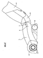
- the connector portion 16 is pivotally secured to the lower housing portion 12, as best illustrated in Figures 2a , 2b and 3 ; Figure 2 showing the general relationship between the components in normal use and Figure 3 showing the general relationship between the components in storage or when reaching under furniture for example.
- the ability to reach the flat position shown in Figure 2b is provided by the raised pivot axis A of the connector portion 16 relative to the lower housing portion 12 with respect to the ground.
- the upper housing portion 14 is pivotable about an axis B between a closed position shown in Figures 1 and 2 and an open position as shown in Figures 4 and 5 .
- the upper housing portion of 14 is retained in the closed position by means of catches 22, located towards either side of the head 10.
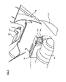
- the catches 22 comprise a conventional form of over-centre mechanism, as shown in Figure 3 . They operate as follows: lower link 22a is released by pulling upwards as indicated by arrow X, the catch 22 then pivots up and forwards as indicated by arrow Y to release. The reverse is undertaken to resecure the catches 22. Thus it can be seen that the catches 22 can be released, and resecured, without the use of any tool.
- the lower housing portion 12 provides ground engaging wheels 20 to either side towards the rear thereof. It also provides pivotally mounted brush bar retaining cradles 24 to either side towards the front thereof, for support of a brush bar 26.
- the brush bar retaining cradles 24 are pivotable about an axis C located rearwardly and above the location of the brush bar 26 in use.
- the brush bar 26 has on either end a removable end cap 28. The purpose of the pivotable brush bar retaining cradles 24 and removable end caps 28 will become apparent in due course when the removability of the brush bar 26 is described.
- the brush bar 26 is selectively drivable by means of a drive mechanism which will now be described.
- the lower housing portion 12 provides support for an electric motor 30 and associated control unit 32, and motor cover 34 (shown removed in Figures 4 and 5 ).
- the motor 30 provides the drive for the brush bar 26 via a drive belt (not shown).
- the path of the drive belt is enclosed within a cover comprising a first cover part 40 provided by the lower housing portion 12, and a second cover part 42 provided by the upper housing portion 14.
- the cover provided by first and second cover parts 40, 42 means that the drive belt is completely enclosed in use and thus protected from dirt and damage.
- the control unit 32 for the motor 30 includes a switch 44 which is activated by a protrusion 46 provided on an inner surface of the upper housing portion 14. As the upper housing portion 14 is moved from its open position to its closed position the protrusion 46 operates external button 48 of the switch 44.
- the switch 44 is provided as a safety feature to ensure that the motor 30 cannot be operated-to drive the brush bar 26 whilst the upper housing portion 14 is in its open position. Thus, the motor 30 can only be operated to drive the brush bar 26 when the protrusion 46 has operated the button 48 to close switch 44.
- the control unit 32 further includes indicator lights 50, in this embodiment three of them, on its upper surface which can be viewed through an opening in motor cover 34, and an opening 52 In the upper housing portion 14.
- the indicator lights 50 can, for example, be used to indicate that (a) a supply of electricity is provided to the control unit 32, (b) the motor 30 is being operated such that the brush bar 26 is rotating, and (c) that the brush bar is not rotating, i.e. has been fouled by some debris.
- the lights for (a) and (b) may be green LEDs and the light for (c) may be a red LED.
- the number of indicator lights provided and what they indicate may be varied as desired, for example they may indicate whether the brush bar is rotating at full speed or at a lower speed.
- the airflow opening 54 communicates with airflow passages 56 within the head 10 and positioned to either side of the motor 30 and control unit 32, and defined partly by the lower housing portion 12 and partly by the upper housing portion 14.
- the airflow passages 56 combine to form a single airflow passage (not shown) where the upper and lower housing portions 12, 14 are secured to the connector portion 16.
- the use of two airflow passages 56 to connect the airflow opening 54 to the single airflow passage which passes up the wand 18 of the suction cleaner provides for more even suction across the width of the airflow opening 54.
- the construction of the head 10 as described above provides the ability for simple removal of the brush bar 26 for, for example, cleaning or maintenance of the head 10.
- To remove the brush bar 26 the following steps are taken.
- the catches 22 are released and the upper housing portion 14 is pivoted upwardly about the axis B. In that position of the brush bar 26 is accessible from above, below and the front. This is particularly the case because the lower housing portion 12 does not include any part which extends laterally between its sides forward of the brush bar 26, and because the head 10 does not include any sole plate or the like.
- the brush bar retaining cradles 24 are then gripped and pivoted upwardly and rearwardly about axis C as indicated by arrows G in Figure 4 .
- the end caps 28 are gripped and pulled outwardly as indicated by arrows H in Figure 4 , to remove them from the ends of the brush bar 26.
- the brush bar 26 can then be lifted upwards and out of the head 10 as indicated by arrow I in Figure 4 , with the appropriate lateral movement to remove the brush bar 26 from the drive belt.
- the brush bar 26 can be removed from the head 10 very simply and without the use of any tool. Furthermore, the brush bar 26 can be replaced within the head 10 by simply reversing the steps described above, and again without the use of any tool. Thus, the brush bar 26 can be cleaned and the airflow passages 56 cleared. As a result users of the suction cleaner concerned are much more likely to undertake such simple cleaning and maintenance than would be the case with prior art heads.
- the invention has only been described in use with a selectively driven brush bar, however, it is equally applicable to any other kind of head for such cleaners.
- heads with a rotatable but not driven brush bar and heads without a brush bar but including fixed lines of bristles or a rubber blade.
- the lower housing portion 12 provides support for an electric motor 130 and associated control unit 132, and motor cover as 34 (shown removed in Figures 4 and 5 ).
- the motor 130 provides the drive for the brush bar 26 via motor pinion 135, and a drive belt 136 which is toothed on both internal and external outside surfaces 136a and 136b and which also passes around support wheel 137 (which may or may not be toothed).
- the drive belt 136 engages with drive pinion 138 located on the brush bar 26, by means of its toothed external surface 136b.
- the path of the drive belt 136 is enclosed within a cover comprising a first cover part 140 provided by the lower housing portion 12, and a second cover part (not shown) provided by the upper housing portion 14.
- the cover provided by the first and second cover parts means that the drive belt 136 is completely enclosed in use and thus protected from dirt and damage.
- Tool elements provided with the head 10 may take the form of different kinds of brush bar specifically adapted for different floor surfaces with different bristle densities and/or hardnesses, and other forms such as buffing bars for buffing and polishing-of hard floors with the bristles replaced by pads.
- FIG. 7 illustrates, in a view corresponding to part of Figure 6 , a similar drive arrangement to that of Figure 6 but in a "turbo" head.
- the difference is that instead of the electric motor 130 there is a turbine rotor 160 having blades 161, carried by a rotatably-supported shaft having pinion 135 at its end.
- the rotor 160 is disposed within a housing part 162 of the lower housing portion 12 and a corresponding part (not shown) of the upper housing portion 14 together affording a chamber accommodating the rotor.
- An air inlet to such chamber from the region of the brush bar 26 is indicated at 163, and an outlet (not shown) from the chamber leads to the connector portion 16 in the vicinity of where the air flow passages 56 join.
- part of the suction airstream passes through the chamber causing the rotor 160 to revolve and drive the belt 136, possibly by way of a suitable reduction gearing.
- the turbine may in this case be a unit at least partly having its own housing, disposed within the housing 12,14 of the head 10.
- FIG. 8 of the drawings shows a further embodiment with an electric motor 130 whose shaft is provided with a pulley 165 instead of the pinion 135.
- a belt 166 is entrained around the pulley 165 and a support wheel 167 which is also in the form of a pulley rather than the pinion 137.
- the cross-sectional shape of the interior surface of belt 166 which engages the pulley 165 and support wheel 167 may be of "Vee-belt" form and the pulley and support wheel may be correspondingly shaped to be engaged by the belt.
- the brush bar 26 has a drive surface 168 which is engaged by the external surface of the belt to be driven frictionally thereby.
- the cross- sectional shape of the drive surface part 168 on the brush bar, and of the external surface of the belt. 166 may be that of a vee pulley and belt respectively, or any other suitable profile for frictional driving, e. g. part-circular or possibly even flat.
- Figure 9 shows diagrammatically, in a partly sectioned view, the arrangement of the pulley 165, belt 166, support wheel 167, and brush bar drive wheel part 168 of Figure 6 .
- the support wheel 167 is shown to be biased by springs 169 away from the pulley 165, to maintain tension in the belt between the pulley 165 and support wheel 167 and to establish good frictional driving conditions with the drive surface of the brush bar.
- the belt 166 is shown as having a vee profile on both its internal and external surfaces.
- this shows an embodiment wherein the drive belt 136 is provided with teeth at 136b on its external surface, but its internal surface 136a is not toothed.
- the belt extends around a further support wheel 170 positioned adjacent the pinion 135 and the pinion engages the toothed external surface 136b of the belt.
- the belt engages the brush bar pinion 138 as above described.
- a pulley on the drive shaft of a motor or turbine to engage the external surface of a drive belt of suitable cross-sectional shape, for example as shown in Figures 7 and 9 , frictionally to drive the belt.
Landscapes
- Engineering & Computer Science (AREA)
- Mechanical Engineering (AREA)
- Nozzles For Electric Vacuum Cleaners (AREA)
Description
- The invention relates to a head for a suction cleaner, and in particular to a head including a rotatably driven tool element such as a brush bar, either of the kind adapted for attachment to a wand of a "cylinder" type suction cleaner, or of the kind incorporated in an "upright" type suction cleaner.
- Domestic suction cleaners, more commonly called vacuum cleaners, are generally divided into two kinds; "upright" cleaners in which the head is integral with or at least pivotably connected to the main body of the cleaner, and "cylinder" cleaners in which a hose and/or wand connects any tools such as the head to the main body of the cleaner. In the former kind of cleaner the head usually includes a driven brush bar. In the latter kind all tools originally incorporated fixed brushes, but more recently various head designs have been introduced incorporating rotatably driven brushes.
- The means of driving such brushes vary. In general in upright cleaners the brush bar is driven by a belt powered by electric motor, this being either the main motor which provides the suction or a secondary motor provided specifically for that purpose. In cylinder cleaners, some use the suction of the main vacuum cleaner and a turbine in the head to drive the brush, whilst others include an electric motor in the head powered by an electrical supply provided down the hose/wand combination. In the latter case the drive to the brush in the head may be by means of a belt or direct.
- The problem with driven brushes, in both upright and cylinder vacuum cleaners, is that they often get entangled with elongate items which have been vacuumed up, such as pieces of string or ribbon, or even long human hair. This can result in significantly degraded performance because of restricted airflow around the brush and therefore it is important to remove such entangled items in order to obtain good performance from the vacuum cleaner. However, experience has shown that most users simply do not clear the brush bar as to do so in the prior art cleaners require the use of tools, generally to remove a sole plate of the head.
- A problem which is common to all heads for suction cleaners, both with and without brush bars, is that of the airflow passages within the heads becoming fully or partially blocked by inappropriate debris which has been sucked up. Clearly in such circumstances the performance of the cleaner is severely degraded and can only be restored by clearance of the blockage.
- However, it has been found that with prior art suction cleaners users are very slow both to realise that a blockage has occurred and also to take the necessary action to clear it. The latter is largely because of the need to use to tools to open the head of the suction cleaner and because the task, even with tools, tends to be quite difficult to perform requiring a high degree of dexterity, as it can include removing and reinserting screws.
-
US5500979 describes a head for a suction cleaner in which a belt-driven rotary tool is held between a lower housing and a movable upper housing. - It is an object of the present invention to provide an improved form of cleaning tool employing a rotatably driven brush which mitigates the above described problems.
- According to the present invention there is provided a head for a suction cleaner having the features of claim 1.
- The head of the invention provides the advantage that it can readily be opened for simple clearing of the airflow passages and general maintenance purposes.
- Furthermore it is preferable that the head does not include a sole plate, or the like.
- Conveniently, when the upper housing portion is in the closed position it defines, in combination with the lower housing portion, an airflow opening which in use is adjacent the ground and within which the brush bar is located if included in the head.
- Preferably it further includes at least one catch to retain the upper housing portion in the closed position which is releasable without the use of any tool.
- When the upper housing portion is in the open position it may be the case that airflow paths within the head are accessible for cleaning or maintenance.
- It is preferred if, the brush bar is selectively driven by a-drive mechanism and when the upper housing portion is in the open position, the drive mechanism is accessible for cleaning or maintenance. In such circumstances the brush bar is readily removable without the use of any tool.
- The head may further include a switch for control of the drive mechanism which is open when the upper housing portion is in the open position, such that the drive mechanism cannot be operated, and closed when the upper housing portion is in the closed position, such that the drive mechanism can be operated. In such cases the switch may be activated by a protrusion on an inner surface of the upper housing portion which contacts the switch when the upper housing portion is moved to the closed position.
- The drive mechanism may include an electric motor within the head.
- As an alternative to including an electric motor, the drive mechanism may include a turbine within the head. In this case, the accessible air flow paths within the head, when the upper housing portion is moved to its open position, may include a path to and/or from the turbine, or possibly even through the turbine providing access to a rotor thereof in case it should require to be cleaned.
- Preferably the drive mechanism further includes a drive pinion provided on the tool element, and the drive belt is toothed on its external surface and engages with the drive pinion.
- The drive mechanism may further include a turbine which drives a turbine pinion engaging the belt. Alternatively it may include an electric motor which drives motor pinion engaging the belt.
- The drive belt may be toothed on its internal surface, and pass around and engage with the turbine or motor pinion. Alternatively the motor or turbine pinion may engage the toothed external surface of the drive belt.
- As a possible alternative to the use of a toothed belt, a circumferential drive surface may be provided on the tool element which is engaged frictionally by the external surface of the belt. The drive surface on the tool element may be in the form of a pulley, e. g. of vee section, and the external surface of the belt have an appropriate corresponding cross-sectional shape to cooperate therewith.
- Just as a motor or turbine may have a pinion which engages the toothed internal or external surface of the drive belt, the motor or turbine may have a drive wheel, e. g. a pulley which frictionally engages the internal or external surface of the drive belt.
- Conveniently the drive mechanism further includes a support wheel around which the drive belt also passes, and which holds the drive belt adjacent to the tool element and in engagement with the drive pinion on the tool element.
- The use of a drive belt which does not pass around the tool element enhances the ability of the tool element to be readily removed without the use of any tools or implements, which means that, in addition to the advantage of easy clearing of any entanglement from the tool element, a particular type of tool element may if required be replaced by an alternative type of tool element intended to perform a different function. For example a brush bar intended for use on a carpeted surface may be replaced by a different type of brush bar intended for use on a hard surface, or by a buffing or polishing tool for example. Hitherto the difficultly of removing the tool element has meant that suction cleaner heads have not generally been intended for use with different types of tool element.
- Thus, there may be provided a plurality of tool elements, adapted to perform different functions, any one of which may be installed in-the head as desired.
- According to a second aspect of the present invention there is provided a suction cleaner including a head according to the invention.
- Embodiments of the invention will now be described, by way of example only, with reference to the accompanying drawings in which:
-
Figure 1 is perspective view of an embodiment of a head for a suction cleaner according to the invention; -
Figures 2a &2b are side views of the head ofFigure 1 , connected to the wand of a suction cleaner, and in (a) a first position and (b) a second position; -
Figure 3 is a rear perspective view of part of the head ofFigure 1 , showing the catch in more detail; -
Figure 4 is a perspective view of the head ofFigure 1 with the upper housing portion In its open position, and the brush bar in the process of being removed; -
Figure 5 is an enlarged perspective view of part of the head ofFigure 1 with the cover of the electric motor removed for clarity; -
Figure 6 is an enlarged perspective view of an drive mechanism for the brush bar of the preceding Figures, with the cover of the electric motor and of the drive belt removed; -
Figure 7 is a view corresponding toFigure 6 , but of a modified drive mechanism; -
Figure 8 is a view asFigure 7 , showing yet a furOther modification of drive mechanism; -
Figure 9 is a plan view of part of the mechanism shown inFigure 8 ; and -
Figure 10 is a view asFigures 7 and8 , showing yet a further modification of the drive mechanism. - Referring to the Figures, a
head 10 comprises alower housing portion 12, anupper housing portion 14 and aconnector portion 16 for connection of thehead 10 to awand 18 of a suction cleaner (not shown). Theconnector portion 16 is pivotally secured to thelower housing portion 12, as best illustrated inFigures 2a ,2b and3 ;Figure 2 showing the general relationship between the components in normal use andFigure 3 showing the general relationship between the components in storage or when reaching under furniture for example. The ability to reach the flat position shown inFigure 2b is provided by the raised pivot axis A of theconnector portion 16 relative to thelower housing portion 12 with respect to the ground. - The
upper housing portion 14 is pivotable about an axis B between a closed position shown inFigures 1 and2 and an open position as shown inFigures 4 and5 . The upper housing portion of 14 is retained in the closed position by means ofcatches 22, located towards either side of thehead 10. Thecatches 22 comprise a conventional form of over-centre mechanism, as shown inFigure 3 . They operate as follows:lower link 22a is released by pulling upwards as indicated by arrow X, thecatch 22 then pivots up and forwards as indicated by arrow Y to release. The reverse is undertaken to resecure thecatches 22. Thus it can be seen that thecatches 22 can be released, and resecured, without the use of any tool. - The
lower housing portion 12 providesground engaging wheels 20 to either side towards the rear thereof. It also provides pivotally mounted brush bar retaining cradles 24 to either side towards the front thereof, for support of abrush bar 26. The brush bar retaining cradles 24 are pivotable about an axis C located rearwardly and above the location of thebrush bar 26 in use. Thebrush bar 26 has on either end aremovable end cap 28. The purpose of the pivotable brush bar retaining cradles 24 and removable end caps 28 will become apparent in due course when the removability of thebrush bar 26 is described. - The
brush bar 26 is selectively drivable by means of a drive mechanism which will now be described. Thelower housing portion 12 provides support for anelectric motor 30 and associatedcontrol unit 32, and motor cover 34 (shown removed inFigures 4 and5 ). Themotor 30 provides the drive for thebrush bar 26 via a drive belt (not shown). The path of the drive belt is enclosed within a cover comprising afirst cover part 40 provided by thelower housing portion 12, and asecond cover part 42 provided by theupper housing portion 14. The cover provided by first andsecond cover parts - The
control unit 32 for themotor 30 includes aswitch 44 which is activated by aprotrusion 46 provided on an inner surface of theupper housing portion 14. As theupper housing portion 14 is moved from its open position to its closed position theprotrusion 46 operatesexternal button 48 of theswitch 44. Theswitch 44 is provided as a safety feature to ensure that themotor 30 cannot be operated-to drive thebrush bar 26 whilst theupper housing portion 14 is in its open position. Thus, themotor 30 can only be operated to drive thebrush bar 26 when theprotrusion 46 has operated thebutton 48 to closeswitch 44. - The
control unit 32 further includes indicator lights 50, in this embodiment three of them, on its upper surface which can be viewed through an opening in motor cover 34, and anopening 52 In theupper housing portion 14. The indicator lights 50 can, for example, be used to indicate that (a) a supply of electricity is provided to thecontrol unit 32, (b) themotor 30 is being operated such that thebrush bar 26 is rotating, and (c) that the brush bar is not rotating, i.e. has been fouled by some debris. Conveniently the lights for (a) and (b) may be green LEDs and the light for (c) may be a red LED. Clearly the number of indicator lights provided and what they indicate may be varied as desired, for example they may indicate whether the brush bar is rotating at full speed or at a lower speed. - When the
upper housing portion 14 is in its closed position it, in combination with thelower housing portion 12, defines anairflow opening 54, in which thebrush bar 26 is located. Theairflow opening 54 communicates withairflow passages 56 within thehead 10 and positioned to either side of themotor 30 andcontrol unit 32, and defined partly by thelower housing portion 12 and partly by theupper housing portion 14. Theairflow passages 56 combine to form a single airflow passage (not shown) where the upper andlower housing portions connector portion 16. The use of twoairflow passages 56 to connect theairflow opening 54 to the single airflow passage which passes up thewand 18 of the suction cleaner provides for more even suction across the width of theairflow opening 54. - The construction of the
head 10 as described above provides the ability for simple removal of thebrush bar 26 for, for example, cleaning or maintenance of thehead 10. To remove thebrush bar 26 the following steps are taken. Thecatches 22 are released and theupper housing portion 14 is pivoted upwardly about the axis B. In that position of thebrush bar 26 is accessible from above, below and the front. This is particularly the case because thelower housing portion 12 does not include any part which extends laterally between its sides forward of thebrush bar 26, and because thehead 10 does not include any sole plate or the like. - The brush bar retaining cradles 24 are then gripped and pivoted upwardly and rearwardly about axis C as indicated by arrows G in
Figure 4 . Next the end caps 28 are gripped and pulled outwardly as indicated by arrows H inFigure 4 , to remove them from the ends of thebrush bar 26. Thebrush bar 26 can then be lifted upwards and out of thehead 10 as indicated by arrow I inFigure 4 , with the appropriate lateral movement to remove thebrush bar 26 from the drive belt. - As will be understood the
brush bar 26 can be removed from thehead 10 very simply and without the use of any tool. Furthermore, thebrush bar 26 can be replaced within thehead 10 by simply reversing the steps described above, and again without the use of any tool. Thus, thebrush bar 26 can be cleaned and theairflow passages 56 cleared. As a result users of the suction cleaner concerned are much more likely to undertake such simple cleaning and maintenance than would be the case with prior art heads. - The invention has only been described in use with a selectively driven brush bar, however, it is equally applicable to any other kind of head for such cleaners. For examples heads with a rotatable but not driven brush bar, and heads without a brush bar but including fixed lines of bristles or a rubber blade.
- Referring now to
Figure 6 of the drawings, an embodiment of the brush bar drive mechanism will now be described. Thelower housing portion 12 provides support for anelectric motor 130 and associatedcontrol unit 132, and motor cover as 34 (shown removed inFigures 4 and5 ). Themotor 130 provides the drive for thebrush bar 26 viamotor pinion 135, and adrive belt 136 which is toothed on both internal and externaloutside surfaces 136a and 136b and which also passes around support wheel 137 (which may or may not be toothed). Thedrive belt 136 engages withdrive pinion 138 located on thebrush bar 26, by means of its toothedexternal surface 136b. Thus the drive of thebrush bar 26 is achieved without the need for thedrive belt 136 to pass around thebrush bar 26. - The path of the
drive belt 136 is enclosed within a cover comprising afirst cover part 140 provided by thelower housing portion 12, and a second cover part (not shown) provided by theupper housing portion 14. The cover provided by the first and second cover parts means that thedrive belt 136 is completely enclosed in use and thus protected from dirt and damage. - If it is required to remove/replace the
brush bar 26 in the embodiment ofFigure 6 , it is done essentially as described above in relation to the previous embodiment, being yet further assisted by the fact that thedrive belt 136 does not pass around thebrush bar 26, and hence does not have to be disengaged therefrom and engaged therewith. - Tool elements provided with the
head 10 may take the form of different kinds of brush bar specifically adapted for different floor surfaces with different bristle densities and/or hardnesses, and other forms such as buffing bars for buffing and polishing-of hard floors with the bristles replaced by pads. -
Figure 7 illustrates, in a view corresponding to part ofFigure 6 , a similar drive arrangement to that ofFigure 6 but in a "turbo" head. The difference is that instead of theelectric motor 130 there is aturbine rotor 160 havingblades 161, carried by a rotatably-supportedshaft having pinion 135 at its end. Therotor 160 is disposed within ahousing part 162 of thelower housing portion 12 and a corresponding part (not shown) of theupper housing portion 14 together affording a chamber accommodating the rotor. An air inlet to such chamber from the region of thebrush bar 26 is indicated at 163, and an outlet (not shown) from the chamber leads to theconnector portion 16 in the vicinity of where theair flow passages 56 join. Thus part of the suction airstream passes through the chamber causing therotor 160 to revolve and drive thebelt 136, possibly by way of a suitable reduction gearing. - When the
upper housing portion 14 is pivoted to its open position relative to thelower housing portion 12, it may give access as illustrated to theturbine rotor 160 within its chamber, and the passages for airflow to and from the chamber, to facilitate cleaning of these parts if it is required. However, such cleaning of the turbine is likely to be necessary much less frequently than is cleaning of the brush bar, and thus the pivotal opening of thehousing portion 14 need not give access to the turbine interior. The turbine may in this case be a unit at least partly having its own housing, disposed within thehousing head 10. - Referring now to
Figure 8 of the drawings, this shows a further embodiment with anelectric motor 130 whose shaft is provided with apulley 165 instead of thepinion 135. Abelt 166 is entrained around thepulley 165 and asupport wheel 167 which is also in the form of a pulley rather than thepinion 137. The cross-sectional shape of the interior surface ofbelt 166 which engages thepulley 165 andsupport wheel 167 may be of "Vee-belt" form and the pulley and support wheel may be correspondingly shaped to be engaged by the belt. Thebrush bar 26 has adrive surface 168 which is engaged by the external surface of the belt to be driven frictionally thereby. The cross- sectional shape of thedrive surface part 168 on the brush bar, and of the external surface of the belt. 166 may be that of a vee pulley and belt respectively, or any other suitable profile for frictional driving, e. g. part-circular or possibly even flat. -
Figure 9 shows diagrammatically, in a partly sectioned view, the arrangement of thepulley 165,belt 166,support wheel 167, and brush bardrive wheel part 168 ofFigure 6 . Thesupport wheel 167 is shown to be biased bysprings 169 away from thepulley 165, to maintain tension in the belt between thepulley 165 andsupport wheel 167 and to establish good frictional driving conditions with the drive surface of the brush bar. Thebelt 166 is shown as having a vee profile on both its internal and external surfaces. - Referring finally now to
Figure 10 , this shows an embodiment wherein thedrive belt 136 is provided with teeth at 136b on its external surface, but its internal surface 136a is not toothed. Instead of extending around thepinion 135 driven by an electric motor 130 (or by a turbine), the belt extends around afurther support wheel 170 positioned adjacent thepinion 135 and the pinion engages the toothedexternal surface 136b of the belt. The belt engages thebrush bar pinion 138 as above described. This arrangement of a drive mechanism, using a belt toothed on one only of its surfaces, may be valuable in certain arrangements of brush bar and motor in the head. - It would further alternatively be possible for a pulley on the drive shaft of a motor or turbine to engage the external surface of a drive belt of suitable cross-sectional shape, for example as shown in
Figures 7 and9 , frictionally to drive the belt. - Although the invention has been described in connection with the head of a cylinder type suction cleaner which is secured for use to a wand of the cleaner, it is equally applicable to the heads of upright type suction cleaners.
- In the present specification "comprises" means "includes or consists of and "comprising" means "including or consisting of".
- The features disclosed in the foregoing description, or the following claims, or the accompanying drawings, expressed in their specific forms or in terms of a means for performing the disclosed function, or a method or process for attaining the disclosed result, as appropriate, may, separately, or in any combination of such features, be utilised for realising the invention in diverse forms thereof.
Claims (20)
- A head for a suction cleaner, the head including:a lower housing portion (12) ; andan upper housing portion (14) movable relative to the lower housing portion (12) between a closed position for use and an open position in which airflow passages (56) within the head are opened from above;a rotatably mounted tool element (26, 138, 168) which is exposed from aboveand from the front of the tool element when the upper housing portion (14) is in the open position, anda drive mechanism (130, 135, 136, 138, 160, 166) for rotation of the tool element includes a drive belt (136; 166) having internal and external surfaces (136a, 136b, 166);characterised in thatthe drive belt does not pass around the tool element (26) and the external surface of the drive belt engages the tool element (26) such that with the upper housing portion (14) in the open position the tool element (26) is readily removable.
- A head for a suction cleaner according to claim 1 characterised in that the tool element (26) further includes a drive pinion (138), and in that the external surface (136b) of the drive belt is toothed and engages with the drive pinion.
- A head for a suction cleaner according to claim 1 characterised in that a circumferential drive surface (168) is provided on the tool element and the external surface of the drive belt (166) frictionally engages the drive surface.
- A head for a suction cleaner according to Claim 3 characterised in that the drive surface is a pulley and the external surface of the drive belt has a cross-section which cooperates with the pulley.
- A head for a suction cleaner according to any one of the preceding claims characterised in that it does not include a sole plate.
- A head for a suction cleaner according to any one of the preceding claims characterised in that when the upper housing portion (14) is in the closed position it defines, in combination with the lower housing portion (12), an airflow opening (54) which in use is adjacent the ground.
- A head for a suction cleaner according to Claim 6 characterised in that the tool element (26) is located within the airflow opening
- A head for a suction cleaner according to any one of the preceding claims characterised in that it further includes at least one catch (22) to retain the upper housing portion (14) in the closed position which is releasable without the use of any tool.
- A head for a suction cleaner according to any one of the preceding claims characterised in that when the upper housing portion is in the open position airflow paths within the head are accessible for cleaning or maintenance.
- A head for a suction cleaner according to any one of the preceding claims characterised in that when the upper housing portion (14) is in the open position the drive mechanism is accessible for cleaning or maintenance.
- A head for a suction cleaner according to Claim 10 characterised in that the tool element (26) is readily removable without the use of any tool.
- A head for a suction cleaner according any one of the preceding claims characterised in that it further includes a switch (44) for control of the drive mechanism which is open when the upper housing portion is in the open position, such that the drive mechanism cannot be operated, and closed when the upper housing portion is in the closed position, such that the drive mechanism can be operated.
- A head for a suction cleaner according to Claim 12 characterised in that the switch (44) is activated by a protrusion (46) on an inner surface of the upper housing portion (14) which contacts the switch when the upper housing portion is moved to the closed position.
- A head for a suction cleaner according to any one of claims 1 to 13 characterised in that the drive mechanism further includes a turbine (160) which drives a turbine pinion (135) engaging the drive belt.
- A head for a suction cleaner according to any one of claims 1 to 13 characterised in that the drive mechanism further includes an electric motor (130) which drives a motor pinion (135) engaging the drive belt.
- A head for a suction cleaner according to Claim 14 or 15 characterised in that the drive belt is toothed on its internal surface (136a), passes around, and engages with the turbine or motor pinion.
- A head for a suction cleaner according to any one of claims 3 to 13 characterised in that the turbine or motor pinion engages the toothed external surface (136b) of the drive belt.
- A head for a suction cleaner according to any one of claims 3 to 13 characterised in that the drive mechanism further includes a motor or turbine having a drive wheel which frictionally engages the drive belt.
- A head for a suction cleaner according to any one of the preceding claims characterised in that the drive mechanism further includes a support wheel (137) around which the drive belt also passes, and which holds the drive belt adjacent to and in engagement with the tool element.
- A suction cleaner including a head according to any one of the preceding claims.
Applications Claiming Priority (5)
| Application Number | Priority Date | Filing Date | Title |
|---|---|---|---|
| GB0228481A GB0228481D0 (en) | 2002-12-06 | 2002-12-06 | Head for a suction cleaner |
| GB0228481 | 2002-12-06 | ||
| GB0228478A GB0228478D0 (en) | 2002-12-06 | 2002-12-06 | Head for a suction cleaner |
| GB0228478 | 2002-12-06 | ||
| PCT/GB2003/005301 WO2004052166A1 (en) | 2002-12-06 | 2003-12-05 | Head for a suction cleaner |
Publications (3)
| Publication Number | Publication Date |
|---|---|
| EP1583450A1 EP1583450A1 (en) | 2005-10-12 |
| EP1583450B1 true EP1583450B1 (en) | 2014-03-12 |
| EP1583450B8 EP1583450B8 (en) | 2014-05-07 |
Family
ID=32510396
Family Applications (1)
| Application Number | Title | Priority Date | Filing Date |
|---|---|---|---|
| EP03780348.3A Expired - Lifetime EP1583450B8 (en) | 2002-12-06 | 2003-12-05 | Head for a suction cleaner |
Country Status (8)
| Country | Link |
|---|---|
| US (1) | US7690079B2 (en) |
| EP (1) | EP1583450B8 (en) |
| JP (1) | JP2006508757A (en) |
| AU (1) | AU2003288429B2 (en) |
| ES (1) | ES2459323T3 (en) |
| MX (1) | MXPA05006097A (en) |
| RU (1) | RU2302809C2 (en) |
| WO (1) | WO2004052166A1 (en) |
Families Citing this family (60)
| Publication number | Priority date | Publication date | Assignee | Title |
|---|---|---|---|---|
| GB0228148D0 (en) | 2002-12-03 | 2003-01-08 | Techtronic Ind Co Ltd | Dust separator and collector arrangement for suction cleaner |
| GB0228152D0 (en) | 2002-12-03 | 2003-01-08 | Techtronic Ind Co Ltd | Cyclonic separators for suction cleaners |
| EP1583450B8 (en) | 2002-12-06 | 2014-05-07 | Techtronic Floor Care Technology Limited | Head for a suction cleaner |
| GB2416482B (en) | 2004-07-22 | 2007-12-05 | Techtronic Ind Co Ltd | Hose assembly for suction cleaner |
| GB2417674B (en) | 2004-09-02 | 2007-12-19 | Techtronic Ind Co Ltd | Suction cleaners |
| KR100558581B1 (en) * | 2004-10-29 | 2006-03-13 | 삼성광주전자 주식회사 | A brush assembly and a vaccum cleaner having the same |
| GB2422090B (en) * | 2005-01-12 | 2008-07-02 | Techtronic Ind Co Ltd | Head for a suction cleaner |
| GB2423037A (en) | 2005-02-15 | 2006-08-16 | Techtronic Ind Co Ltd | Cyclonic separator for suction cleaner |
| USD545511S1 (en) | 2005-04-08 | 2007-06-26 | Vax Limited | Dry only canister machine |
| GB2425246B (en) | 2005-04-21 | 2008-07-23 | Vax Ltd | Dust separator/collector assembly for suction cleaner |
| US8621709B2 (en) | 2006-12-12 | 2014-01-07 | G.B.D. Corp. | Multi-strut cleaning head |
| EP2113182B1 (en) * | 2008-05-02 | 2011-07-06 | Black & Decker, Inc. | Vacuum cleaner control system |
| US20100125969A1 (en) * | 2008-11-24 | 2010-05-27 | Michael Genna | Cleaning apparatus |
| CA2658369A1 (en) * | 2009-03-13 | 2010-09-13 | G.B.D. Corp. | Surface cleaning head |
| CA2684168A1 (en) * | 2009-10-30 | 2011-04-30 | G.B.D. Corp. | Surface cleaning head |
| SI23237A (en) * | 2009-12-21 | 2011-06-30 | AljaĹľ PELICON | Vacuum cleaner attachment |
| US8508178B2 (en) | 2010-03-26 | 2013-08-13 | Shop Vac Corporation | Torque based electronic pulse width modulation control system for a switched reluctance motor |
| CN102578965B (en) | 2011-01-14 | 2014-04-16 | 泰怡凯电器(苏州)有限公司 | Vacuum cleaner and suction nozzle thereof |
| TWI594924B (en) * | 2011-02-03 | 2017-08-11 | Yuyama Manufacturing Co Ltd | Pharmacy sub-package device |
| WO2012150929A1 (en) * | 2011-05-03 | 2012-11-08 | Shop Vac Corporation | Removable circuit board assembly for a vacuum |
| DE102013201575A1 (en) * | 2013-01-31 | 2014-07-31 | BSH Bosch und Siemens Hausgeräte GmbH | household appliance |
| JP6267898B2 (en) * | 2013-09-05 | 2018-01-24 | シャープ株式会社 | Suction port body and electric vacuum cleaner provided with the same |
| JP6303809B2 (en) * | 2014-05-23 | 2018-04-04 | 三菱電機株式会社 | Electric vacuum cleaner |
| US11992172B2 (en) | 2018-10-19 | 2024-05-28 | Sharkninja Operating Llc | Agitator for a surface treatment apparatus and a surface treatment apparatus having the same |
| US9955832B2 (en) | 2015-01-30 | 2018-05-01 | Sharkninja Operating Llc | Surface cleaning head with removable non-driven agitator having cleaning pad |
| US9655486B2 (en) | 2015-01-30 | 2017-05-23 | Sharkninja Operating Llc | Surface cleaning head including removable rotatable driven agitator |
| US11607095B2 (en) | 2015-01-30 | 2023-03-21 | Sharkninja Operating Llc | Removable rotatable driven agitator for surface cleaning head |
| EP3250102B1 (en) * | 2015-01-30 | 2022-01-26 | SharkNinja Operating LLC | Surface cleaning head including openable agitator chamber and removable agitators for use therein |
| US9456723B2 (en) | 2015-01-30 | 2016-10-04 | Sharkninja Operating Llc | Surface cleaning head including openable agitator chamber and a removable rotatable agitator |
| USD792669S1 (en) | 2015-05-14 | 2017-07-18 | Sharkninja Operating Llc | Vacuum cleaner body |
| USD769557S1 (en) | 2015-05-14 | 2016-10-18 | Sharkninja Operating Llc | Vacuum cleaner |
| USD779752S1 (en) | 2015-05-14 | 2017-02-21 | Sharkninja Operating Llc | Vacuum cleaner head |
| USD781013S1 (en) | 2015-05-18 | 2017-03-07 | Sharkninja Operating Llc | Vacuum cleaner head cover |
| USD789006S1 (en) | 2015-05-15 | 2017-06-06 | Sharkninja Operating Llc | Vacuum cleaner |
| USD788393S1 (en) | 2015-05-18 | 2017-05-30 | Sharkninja Operating Llc | Vacuum cleaner head |
| USD785258S1 (en) | 2015-05-22 | 2017-04-25 | Sharkninja Operating Llc | Vacuum cleaner body |
| USD784636S1 (en) | 2015-05-22 | 2017-04-18 | Sharkninja Operating Llc | Vacuum cleaner |
| US10076183B2 (en) * | 2015-08-14 | 2018-09-18 | Sharkninja Operating Llc | Surface cleaning head |
| US10702108B2 (en) | 2015-09-28 | 2020-07-07 | Sharkninja Operating Llc | Surface cleaning head for vacuum cleaner |
| CN108175334A (en) | 2015-10-21 | 2018-06-19 | 尚科宁家运营有限公司 | Surface cleaning head with dual rotary agitator |
| US11647881B2 (en) | 2015-10-21 | 2023-05-16 | Sharkninja Operating Llc | Cleaning apparatus with combing unit for removing debris from cleaning roller |
| CA2971136A1 (en) * | 2016-01-04 | 2017-07-13 | Jiangsu Midea Cleaning Appliances Co., Ltd. | Ground brush for vacuum cleaner and vacuum cleaner with the same |
| CN205433565U (en) * | 2016-01-04 | 2016-08-10 | 江苏美的清洁电器股份有限公司 | Scrubbing brush and dust catcher |
| USD837469S1 (en) | 2016-07-22 | 2019-01-01 | Sharkninja Operating Llc | Vacuum cleaner |
| CA3036354C (en) | 2016-09-09 | 2023-01-03 | Sharkninja Operating Llc | Agitator with hair removal |
| AU2017101723A4 (en) | 2016-12-16 | 2018-01-18 | Bissell Inc. | Surface cleaning apparatus |
| EP3363341A1 (en) * | 2017-02-20 | 2018-08-22 | Koninklijke Philips N.V. | Rotatable brush |
| CN114403741B (en) | 2017-03-10 | 2024-02-27 | 尚科宁家运营有限公司 | Blender with cleaner and hair removal |
| US11202542B2 (en) | 2017-05-25 | 2021-12-21 | Sharkninja Operating Llc | Robotic cleaner with dual cleaning rollers |
| CN110809422B (en) | 2017-05-26 | 2021-04-13 | 尚科宁家运营有限公司 | Hair Cutting Brush Roller |
| CA185652S (en) | 2017-07-25 | 2021-03-17 | Sharkninja Operating Llc | Vacuum cleaner |
| US11458771B2 (en) | 2017-08-31 | 2022-10-04 | Sharkninja Operating Llc | Wheels having shock absorbing characteristics and a surface treatment apparatus using the same |
| US11672393B2 (en) * | 2017-12-27 | 2023-06-13 | Sharkninja Operating Llc | Cleaning apparatus with selectable combing unit for removing debris from cleaning roller |
| US11247245B2 (en) | 2017-12-27 | 2022-02-15 | Sharkninja Operating Llc | Cleaning apparatus with anti-hair wrap management systems |
| AU2019331419B2 (en) | 2018-08-27 | 2022-08-04 | Techtronic Floor Care Technology Limited | Floor cleaner |
| CN116158688A (en) | 2018-10-19 | 2023-05-26 | 尚科宁家运营有限公司 | Vacuum cleaners and agitators for vacuum cleaners |
| EP3897330B1 (en) | 2018-12-21 | 2023-09-06 | Tennant Company | Sweeper/scrubber system capable of handling large debris |
| JP7526488B2 (en) * | 2019-07-31 | 2024-08-01 | アイリスオーヤマ株式会社 | Suction port body of vacuum cleaner, and vacuum cleaner |
| CN114630609A (en) | 2019-10-31 | 2022-06-14 | 创科无线普通合伙 | Brush roll for floor cleaner |
| CN114652244B (en) * | 2022-03-02 | 2023-03-07 | 深圳市杉川机器人有限公司 | Cleaning system |
Family Cites Families (49)
| Publication number | Priority date | Publication date | Assignee | Title |
|---|---|---|---|---|
| US1829582A (en) * | 1928-12-31 | 1931-10-27 | Electric Vacuum Cleaner Co | Vacuum cleaner |
| US1833961A (en) * | 1929-03-19 | 1931-12-01 | Bass Rubin | Vacuum cleaner |
| US1968530A (en) * | 1930-12-12 | 1934-07-31 | Quadrex Corp | Electric sweeper |
| US1900889A (en) * | 1931-02-06 | 1933-03-07 | Hoover Co | Suction cleaner |
| US2482166A (en) * | 1947-07-16 | 1949-09-20 | William I Gage | Stationary filter type suction cleaner |
| US2910721A (en) * | 1955-12-15 | 1959-11-03 | Burrage & Boyde Ltd | Non-electric vacuum cleaning machines |
| US2963270A (en) * | 1956-09-17 | 1960-12-06 | Preco Inc | Turbine mechanism, more particularly for air flow operation for vacuum cleaning |
| NL134452C (en) * | 1966-02-18 | |||
| US3924085A (en) * | 1974-03-18 | 1975-12-02 | Gen Electric | Safety-start device and circuit controller for domestic appliance |
| FR2425227A1 (en) | 1978-05-11 | 1979-12-07 | So Ve Mar Co Europ | Storage container for vacuum cleaner hose - consists of groove moulded in plastics housing surface with diameter less than that of hose |
| DE8227688U1 (en) | 1982-10-02 | 1983-01-13 | Rowenta-Werke Gmbh, 6050 Offenbach | VACUUM CLEANER |
| DE3834686C1 (en) | 1988-10-12 | 1989-12-07 | Rowenta-Werke Gmbh, 6050 Offenbach, De | Floor-type vacuum cleaner (cylinder vacuum cleaner) |
| DE8913502U1 (en) * | 1989-11-15 | 1990-01-18 | Rowenta-Werke Gmbh, 6050 Offenbach | Electric vacuum cleaner |
| US4980945A (en) * | 1989-11-27 | 1991-01-01 | Whirlpool Corporation | Safety interlock device for a vacuum cleaner |
| US5078761A (en) * | 1990-07-06 | 1992-01-07 | Notetry Limited | Shroud |
| NL9002668A (en) * | 1990-12-05 | 1992-07-01 | Philips Nv | VACUUM CLEANER. |
| DE9109809U1 (en) * | 1991-08-07 | 1991-10-31 | Wessel-Werk GmbH & Co. KG, 5226 Reichshof | Active vacuum cleaner nozzle |
| US5309601A (en) * | 1992-10-16 | 1994-05-10 | White Consolidated Industries, Inc. | Vacuum cleaner with improved assembly |
| DE4411526A1 (en) * | 1994-04-02 | 1995-10-05 | Fedag Romanshorn Fa | Suction cleaning device |
| JPH0866338A (en) * | 1994-08-30 | 1996-03-12 | Sharp Corp | Upright vacuum cleaner |
| DE9420797U1 (en) | 1994-12-28 | 1995-06-01 | Steuer, Herbert, 61348 Bad Homburg | Storage aid for vacuum cleaner suction pipe |
| SE508524C2 (en) | 1997-02-13 | 1998-10-12 | Electrolux Ab | Device for a cyclone vacuum cleaner |
| JP3609582B2 (en) * | 1997-06-23 | 2005-01-12 | 三洋電機株式会社 | Electric vacuum cleaner |
| US5960514A (en) | 1997-11-10 | 1999-10-05 | The Hoover Company | Wheel driven suction nozzle |
| US6226832B1 (en) * | 1998-04-23 | 2001-05-08 | Matsushita Home Appliance Corporation Of America | Easy maintenance vacuum cleaner |
| JP2000037327A (en) | 1998-07-23 | 2000-02-08 | Matsushita Electric Ind Co Ltd | Floor nozzle for vacuum cleaner |
| US6350292B1 (en) * | 1998-11-24 | 2002-02-26 | Lg Electronics Inc. | Cyclone collector for a vacuum cleaner having a flow guide |
| DE29900460U1 (en) | 1999-01-14 | 2000-07-06 | Wap Reinigungssysteme Gmbh & Co, 89287 Bellenberg | Transport aid for vacuum cleaners |
| EA003308B1 (en) * | 1999-02-04 | 2003-04-24 | Общество с ограниченной ответственностью Фирма "Дата-Центр" | Method for determining the authenticity, the value and the decay level of banknotes and sorting and counting device |
| AU2697800A (en) * | 1999-02-24 | 2000-09-14 | Lg Electronics Inc. | Cyclone dust collector in vacuum cleaner |
| DE19914574C1 (en) * | 1999-03-31 | 2000-11-23 | Duepro Ag Romanshorn | Electric vacuum cleaner floor cleaning tool has dirt collection container for relatively large dirt particles immediately behind brush chamber for rotating brush roller |
| DE10001467B4 (en) * | 2000-01-15 | 2004-04-08 | Düpro AG | vacuum cleaning tool |
| US6513190B1 (en) * | 2000-04-21 | 2003-02-04 | The Hoover Company | Turbine powered vacuum cleaner nozzle |
| FR2808988B1 (en) * | 2000-05-16 | 2002-07-19 | Seb Sa | WASTE COLLECTOR FOR VACUUM CLEANER |
| GB2367510B (en) | 2000-07-06 | 2003-12-10 | John Herbert North | Improved air/particle separator |
| KR100437371B1 (en) * | 2000-07-26 | 2004-06-25 | 삼성광주전자 주식회사 | Cyclone dust-collecting apparatus for Vaccum Cleaner |
| DE10110768A1 (en) | 2000-08-31 | 2002-03-14 | Duepro Ag Romanshorn | Vacuum cleaning tool has optimized air turbine with total volume between axial ends of turbine, turbine casing of 40,000 to 170,000 mm3; center volume of about 30-45 per cent of total |
| KR100382451B1 (en) * | 2000-11-06 | 2003-05-09 | 삼성광주전자 주식회사 | Cyclone dust-collecting apparatus for vacuum cleaner |
| KR100398684B1 (en) * | 2000-11-27 | 2003-09-19 | 삼성광주전자 주식회사 | Cyclone dust-collecting apparatus for vacuum cleaner |
| KR100437369B1 (en) * | 2001-01-10 | 2004-06-25 | 삼성광주전자 주식회사 | Cyclone dust-collecting apparatus for Vacuum Cleaner |
| US6772475B2 (en) * | 2001-02-06 | 2004-08-10 | The Hoover Company | Suction nozzle configuration |
| DE10110771A1 (en) * | 2001-03-07 | 2002-09-19 | Duepro Ag Romanshorn | Vacuum cleaner for floor surfaces, especially smooth floors, has suction air inlet and outlet windows in slightly mutually inclined suction chamber side walls with inlet opposite baffle wall |
| KR100390608B1 (en) * | 2001-03-12 | 2003-07-07 | 삼성광주전자 주식회사 | Cyclone dust colleting apparatus for Vacuum Cleaner |
| KR100444322B1 (en) * | 2001-12-12 | 2004-08-16 | 삼성광주전자 주식회사 | Cyclone dust-collecting apparatus for Vacuum Cleaner |
| DE10235123A1 (en) | 2002-08-01 | 2004-02-19 | Vorwerk & Co. Interholding Gmbh | Cleaning device with an electric drive |
| GB0228153D0 (en) | 2002-12-03 | 2003-01-08 | Techtronic Ind Co Ltd | Suction cleaners |
| GB0228148D0 (en) | 2002-12-03 | 2003-01-08 | Techtronic Ind Co Ltd | Dust separator and collector arrangement for suction cleaner |
| GB0228152D0 (en) | 2002-12-03 | 2003-01-08 | Techtronic Ind Co Ltd | Cyclonic separators for suction cleaners |
| EP1583450B8 (en) | 2002-12-06 | 2014-05-07 | Techtronic Floor Care Technology Limited | Head for a suction cleaner |
-
2003
- 2003-12-05 EP EP03780348.3A patent/EP1583450B8/en not_active Expired - Lifetime
- 2003-12-05 MX MXPA05006097A patent/MXPA05006097A/en active IP Right Grant
- 2003-12-05 US US10/537,382 patent/US7690079B2/en not_active Expired - Lifetime
- 2003-12-05 WO PCT/GB2003/005301 patent/WO2004052166A1/en not_active Ceased
- 2003-12-05 JP JP2004558785A patent/JP2006508757A/en active Pending
- 2003-12-05 RU RU2005121279/12A patent/RU2302809C2/en not_active IP Right Cessation
- 2003-12-05 AU AU2003288429A patent/AU2003288429B2/en not_active Ceased
- 2003-12-05 ES ES03780348.3T patent/ES2459323T3/en not_active Expired - Lifetime
Also Published As
| Publication number | Publication date |
|---|---|
| US20060179604A1 (en) | 2006-08-17 |
| EP1583450B8 (en) | 2014-05-07 |
| AU2003288429A1 (en) | 2004-06-30 |
| AU2003288429B2 (en) | 2008-01-10 |
| RU2302809C2 (en) | 2007-07-20 |
| JP2006508757A (en) | 2006-03-16 |
| US7690079B2 (en) | 2010-04-06 |
| RU2005121279A (en) | 2006-01-20 |
| MXPA05006097A (en) | 2006-05-25 |
| WO2004052166A1 (en) | 2004-06-24 |
| ES2459323T3 (en) | 2014-05-09 |
| EP1583450A1 (en) | 2005-10-12 |
Similar Documents
| Publication | Publication Date | Title |
|---|---|---|
| US7690079B2 (en) | Head for a suction cleaner | |
| CA2455440C (en) | Traction wheel powered edge cleaner | |
| EP1748719B1 (en) | Tool for a surface treating appliance | |
| JP5118726B2 (en) | Surface treatment head | |
| US6711777B2 (en) | Turbine powered vacuum cleaner nozzle | |
| US6892420B1 (en) | Vacuum cleaner with hair wrap cutter | |
| JP5600509B2 (en) | Surface treatment head | |
| JP5346325B2 (en) | Surface treatment head | |
| JP2006312066A (en) | Electric vacuum cleaner | |
| JP4482034B2 (en) | Vacuum cleaning head | |
| EP2405796A1 (en) | A surface treating head | |
| JP4468440B2 (en) | Vacuum cleaner and its suction port | |
| CN100531646C (en) | Head for a suction cleaner | |
| JP2004147759A (en) | Electric cleaner | |
| JP3877481B2 (en) | Suction port and circulating vacuum cleaner | |
| CA1223754A (en) | Guide for a driven endless belt | |
| JP2010035829A (en) | Suction port body and vacuum cleaner | |
| JP2020000563A (en) | Suction tool for vacuum cleaner and vacuum cleaner including the suction tool | |
| CA2578315A1 (en) | Traction wheel powered edge cleaner | |
| JPH11206636A (en) | Vacuum cleaner and its suction body |
Legal Events
| Date | Code | Title | Description |
|---|---|---|---|
| PUAI | Public reference made under article 153(3) epc to a published international application that has entered the european phase |
Free format text: ORIGINAL CODE: 0009012 |
|
| 17P | Request for examination filed |
Effective date: 20050630 |
|
| AK | Designated contracting states |
Kind code of ref document: A1 Designated state(s): AT BE BG CH CY CZ DE DK EE ES FI FR GB GR HU IE IT LI LU MC NL PT RO SE SI SK TR |
|
| AX | Request for extension of the european patent |
Extension state: AL LT LV MK |
|
| DAX | Request for extension of the european patent (deleted) | ||
| RBV | Designated contracting states (corrected) |
Designated state(s): DE ES FR GB IT |
|
| RIN1 | Information on inventor provided before grant (corrected) |
Inventor name: ELSWORTHY, CHRISTOPHER THOMAS Inventor name: BURNHAM, GAVIN Inventor name: BODDY, ANDREW, DAVID Inventor name: PROUD, REUBEN Inventor name: IVARSSON, BENGT IVAR ANDERS |
|
| 17Q | First examination report despatched |
Effective date: 20100512 |
|
| GRAP | Despatch of communication of intention to grant a patent |
Free format text: ORIGINAL CODE: EPIDOSNIGR1 |
|
| INTG | Intention to grant announced |
Effective date: 20130923 |
|
| GRAS | Grant fee paid |
Free format text: ORIGINAL CODE: EPIDOSNIGR3 |
|
| GRAA | (expected) grant |
Free format text: ORIGINAL CODE: 0009210 |
|
| AK | Designated contracting states |
Kind code of ref document: B1 Designated state(s): DE ES FR GB IT |
|
| REG | Reference to a national code |
Ref country code: GB Ref legal event code: FG4D |
|
| RAP2 | Party data changed (patent owner data changed or rights of a patent transferred) |
Owner name: TECHTRONIC FLOOR CARE TECHNOLOGY LIMITED |
|
| REG | Reference to a national code |
Ref country code: DE Ref legal event code: R096 Ref document number: 60345859 Country of ref document: DE Effective date: 20140424 |
|
| REG | Reference to a national code |
Ref country code: ES Ref legal event code: FG2A Ref document number: 2459323 Country of ref document: ES Kind code of ref document: T3 Effective date: 20140509 |
|
| REG | Reference to a national code |
Ref country code: DE Ref legal event code: R081 Ref document number: 60345859 Country of ref document: DE Owner name: TECHTRONIC FLOOR CARE TECHNOLOGY LIMITED, VG Free format text: FORMER OWNER: TECHTRONIC INDUSTRIES CO. LTD., HONG KONG, HK Effective date: 20140313 Ref country code: DE Ref legal event code: R081 Ref document number: 60345859 Country of ref document: DE Owner name: TECHTRONIC FLOOR CARE TECHNOLOGY LIMITED, VG Free format text: FORMER OWNER: TECHTRONIC FLOOR CARE TECHNOLOGY LTD., ROAD TOWN, VG Effective date: 20140422 Ref country code: DE Ref legal event code: R081 Ref document number: 60345859 Country of ref document: DE Owner name: TECHTRONIC FLOOR CARE TECHNOLOGY LIMITED, VG Free format text: FORMER OWNER: TECHTRONIC INDUSTRIES CO., LTD., HONG KONG, CN Effective date: 20140331 Ref country code: DE Ref legal event code: R081 Ref document number: 60345859 Country of ref document: DE Owner name: TECHTRONIC FLOOR CARE TECHNOLOGY LIMITED, ROAD, VG Free format text: FORMER OWNER: TECHTRONIC INDUSTRIES CO. LTD., HONG KONG, HK Effective date: 20140313 Ref country code: DE Ref legal event code: R081 Ref document number: 60345859 Country of ref document: DE Owner name: TECHTRONIC FLOOR CARE TECHNOLOGY LIMITED, ROAD, VG Free format text: FORMER OWNER: TECHTRONIC INDUSTRIES CO., LTD., HONG KONG, CN Effective date: 20140331 Ref country code: DE Ref legal event code: R081 Ref document number: 60345859 Country of ref document: DE Owner name: TECHTRONIC FLOOR CARE TECHNOLOGY LIMITED, ROAD, VG Free format text: FORMER OWNER: TECHTRONIC FLOOR CARE TECHNOLOGY LTD., ROAD TOWN, TORTOLA, VG Effective date: 20140422 |
|
| REG | Reference to a national code |
Ref country code: DE Ref legal event code: R097 Ref document number: 60345859 Country of ref document: DE |
|
| PLBE | No opposition filed within time limit |
Free format text: ORIGINAL CODE: 0009261 |
|
| STAA | Information on the status of an ep patent application or granted ep patent |
Free format text: STATUS: NO OPPOSITION FILED WITHIN TIME LIMIT |
|
| 26N | No opposition filed |
Effective date: 20141215 |
|
| REG | Reference to a national code |
Ref country code: DE Ref legal event code: R097 Ref document number: 60345859 Country of ref document: DE Effective date: 20141215 |
|
| REG | Reference to a national code |
Ref country code: FR Ref legal event code: PLFP Year of fee payment: 13 |
|
| REG | Reference to a national code |
Ref country code: FR Ref legal event code: PLFP Year of fee payment: 14 |
|
| PG25 | Lapsed in a contracting state [announced via postgrant information from national office to epo] |
Ref country code: IT Free format text: LAPSE BECAUSE OF NON-PAYMENT OF DUE FEES Effective date: 20151205 |
|
| PG25 | Lapsed in a contracting state [announced via postgrant information from national office to epo] |
Ref country code: IT Free format text: LAPSE BECAUSE OF NON-PAYMENT OF DUE FEES Effective date: 20151205 |
|
| PGFP | Annual fee paid to national office [announced via postgrant information from national office to epo] |
Ref country code: IT Payment date: 20151222 Year of fee payment: 13 |
|
| PGRI | Patent reinstated in contracting state [announced from national office to epo] |
Ref country code: IT Effective date: 20170710 |
|
| PG25 | Lapsed in a contracting state [announced via postgrant information from national office to epo] |
Ref country code: IT Free format text: LAPSE BECAUSE OF NON-PAYMENT OF DUE FEES Effective date: 20161205 |
|
| PGRI | Patent reinstated in contracting state [announced from national office to epo] |
Ref country code: IT Effective date: 20170710 |
|
| REG | Reference to a national code |
Ref country code: FR Ref legal event code: PLFP Year of fee payment: 15 |
|
| PGFP | Annual fee paid to national office [announced via postgrant information from national office to epo] |
Ref country code: ES Payment date: 20190102 Year of fee payment: 16 |
|
| REG | Reference to a national code |
Ref country code: ES Ref legal event code: FD2A Effective date: 20210531 |
|
| PG25 | Lapsed in a contracting state [announced via postgrant information from national office to epo] |
Ref country code: ES Free format text: LAPSE BECAUSE OF NON-PAYMENT OF DUE FEES Effective date: 20191206 |
|
| PGFP | Annual fee paid to national office [announced via postgrant information from national office to epo] |
Ref country code: GB Payment date: 20221227 Year of fee payment: 20 Ref country code: FR Payment date: 20221227 Year of fee payment: 20 |
|
| PGFP | Annual fee paid to national office [announced via postgrant information from national office to epo] |
Ref country code: DE Payment date: 20221228 Year of fee payment: 20 |
|
| REG | Reference to a national code |
Ref country code: DE Ref legal event code: R071 Ref document number: 60345859 Country of ref document: DE |
|
| REG | Reference to a national code |
Ref country code: GB Ref legal event code: PE20 Expiry date: 20231204 |
|
| PG25 | Lapsed in a contracting state [announced via postgrant information from national office to epo] |
Ref country code: GB Free format text: LAPSE BECAUSE OF EXPIRATION OF PROTECTION Effective date: 20231204 |
|
| PG25 | Lapsed in a contracting state [announced via postgrant information from national office to epo] |
Ref country code: GB Free format text: LAPSE BECAUSE OF EXPIRATION OF PROTECTION Effective date: 20231204 |