EP1583326A2 - Weiterleitung in Peer-zu-Peer-Netzwerken - Google Patents
Weiterleitung in Peer-zu-Peer-Netzwerken Download PDFInfo
- Publication number
- EP1583326A2 EP1583326A2 EP05102448A EP05102448A EP1583326A2 EP 1583326 A2 EP1583326 A2 EP 1583326A2 EP 05102448 A EP05102448 A EP 05102448A EP 05102448 A EP05102448 A EP 05102448A EP 1583326 A2 EP1583326 A2 EP 1583326A2
- Authority
- EP
- European Patent Office
- Prior art keywords
- node
- peer
- ssrt
- nodes
- entries
- Prior art date
- Legal status (The legal status is an assumption and is not a legal conclusion. Google has not performed a legal analysis and makes no representation as to the accuracy of the status listed.)
- Granted
Links
- 238000000034 method Methods 0.000 claims abstract description 70
- 230000008859 change Effects 0.000 claims abstract description 18
- 238000004891 communication Methods 0.000 claims description 15
- 230000006870 function Effects 0.000 claims description 9
- 230000004044 response Effects 0.000 claims description 7
- 230000000737 periodic effect Effects 0.000 claims description 4
- 230000004931 aggregating effect Effects 0.000 claims 1
- 238000003860 storage Methods 0.000 description 18
- 235000008694 Humulus lupulus Nutrition 0.000 description 16
- 238000012423 maintenance Methods 0.000 description 15
- 230000006978 adaptation Effects 0.000 description 11
- 238000012545 processing Methods 0.000 description 8
- 230000003287 optical effect Effects 0.000 description 5
- 238000013459 approach Methods 0.000 description 4
- 238000010586 diagram Methods 0.000 description 4
- 230000007246 mechanism Effects 0.000 description 3
- 230000006855 networking Effects 0.000 description 3
- 239000000523 sample Substances 0.000 description 3
- 238000012546 transfer Methods 0.000 description 3
- 230000006835 compression Effects 0.000 description 2
- 238000007906 compression Methods 0.000 description 2
- 238000005516 engineering process Methods 0.000 description 2
- 238000001914 filtration Methods 0.000 description 2
- 235000014594 pastries Nutrition 0.000 description 2
- 230000000644 propagated effect Effects 0.000 description 2
- 239000007787 solid Substances 0.000 description 2
- 239000013589 supplement Substances 0.000 description 2
- 230000002776 aggregation Effects 0.000 description 1
- 238000004220 aggregation Methods 0.000 description 1
- 230000003139 buffering effect Effects 0.000 description 1
- 238000010276 construction Methods 0.000 description 1
- 238000013500 data storage Methods 0.000 description 1
- 230000003247 decreasing effect Effects 0.000 description 1
- 230000001419 dependent effect Effects 0.000 description 1
- 238000013461 design Methods 0.000 description 1
- 230000000694 effects Effects 0.000 description 1
- 238000005304 joining Methods 0.000 description 1
- 238000005457 optimization Methods 0.000 description 1
- 238000005192 partition Methods 0.000 description 1
- 230000002093 peripheral effect Effects 0.000 description 1
- 238000013138 pruning Methods 0.000 description 1
- 238000009877 rendering Methods 0.000 description 1
- 230000001360 synchronised effect Effects 0.000 description 1
- 230000002123 temporal effect Effects 0.000 description 1
- 238000012360 testing method Methods 0.000 description 1
- 230000007723 transport mechanism Effects 0.000 description 1
Images


Classifications
-
- H—ELECTRICITY
- H04—ELECTRIC COMMUNICATION TECHNIQUE
- H04L—TRANSMISSION OF DIGITAL INFORMATION, e.g. TELEGRAPHIC COMMUNICATION
- H04L67/00—Network arrangements or protocols for supporting network services or applications
- H04L67/01—Protocols
- H04L67/10—Protocols in which an application is distributed across nodes in the network
- H04L67/104—Peer-to-peer [P2P] networks
-
- H—ELECTRICITY
- H04—ELECTRIC COMMUNICATION TECHNIQUE
- H04L—TRANSMISSION OF DIGITAL INFORMATION, e.g. TELEGRAPHIC COMMUNICATION
- H04L45/00—Routing or path finding of packets in data switching networks
-
- H—ELECTRICITY
- H04—ELECTRIC COMMUNICATION TECHNIQUE
- H04L—TRANSMISSION OF DIGITAL INFORMATION, e.g. TELEGRAPHIC COMMUNICATION
- H04L45/00—Routing or path finding of packets in data switching networks
- H04L45/02—Topology update or discovery
-
- H—ELECTRICITY
- H04—ELECTRIC COMMUNICATION TECHNIQUE
- H04L—TRANSMISSION OF DIGITAL INFORMATION, e.g. TELEGRAPHIC COMMUNICATION
- H04L67/00—Network arrangements or protocols for supporting network services or applications
- H04L67/01—Protocols
- H04L67/10—Protocols in which an application is distributed across nodes in the network
- H04L67/104—Peer-to-peer [P2P] networks
- H04L67/1044—Group management mechanisms
- H04L67/1048—Departure or maintenance mechanisms
-
- H—ELECTRICITY
- H04—ELECTRIC COMMUNICATION TECHNIQUE
- H04L—TRANSMISSION OF DIGITAL INFORMATION, e.g. TELEGRAPHIC COMMUNICATION
- H04L69/00—Network arrangements, protocols or services independent of the application payload and not provided for in the other groups of this subclass
- H04L69/30—Definitions, standards or architectural aspects of layered protocol stacks
- H04L69/32—Architecture of open systems interconnection [OSI] 7-layer type protocol stacks, e.g. the interfaces between the data link level and the physical level
- H04L69/322—Intralayer communication protocols among peer entities or protocol data unit [PDU] definitions
- H04L69/329—Intralayer communication protocols among peer entities or protocol data unit [PDU] definitions in the application layer [OSI layer 7]
Definitions
- the present invention generally relates to peer-to-peer networks, and more particularly relates to routing in peer-to-peer networks.
- Peer-to-peer networks continue to increase in popularity due to many desirable features, such as adaptation, self-organization, load-balancing, fault-tolerance, low cost, high availability, scalability, and ability to provide a large pool of resources.
- peer-to-peer networks have emerged as a popular way to share large amounts of data, such as by peers downloading songs that are referenced as being available for download from another peer in the peer-to-peer network.
- each node in the network may reference one or more other nodes in the network to locate a node having the particular resource, e.g. a particular item of data. Therefore, a series of "hops" may be employed as a request is routed from one node to another until the particular item is located.
- hops may be employed as a request is routed from one node to another until the particular item is located.
- the use of hardware and software resources of the nodes, as well as the network resources of the system also increases.
- the increased number of hops may result in an inefficient use of the resources of the system as well as increase the amount of time utilized to locate the particular item.
- Routing is described in which a routing table is utilized to route messages (e.g., requests for a particular resource and responses to the request) in the peer-to-peer network.
- the routing table may be updated via broadcasting to update entries in the routing table that reference nodes in the peer-to-peer network.
- a maintenance budget utilized to maintain the routing tables of each node is distributed over multiple segments of the resource space of the peer-to-peer network by building dense routing table entries for each segment. Therefore, the overall maintenance budget for maintaining the routing tables may be reduced, which frees the hardware, software, and network resources of the peer-to-peer network to provide the desired message routing functionality.
- a method includes receiving at one of a plurality of nodes in a peer-to-peer network, an indication of a change in membership in the peer-to-peer network by another node in the peer-to-peer network.
- a report is broadcast that describes the change. The report is for receipt by each node referenced in a routing table included in the one node.
- a method in another implementation, includes determining, on a node for inclusion in a peer-to-peer network, available resources of the node for communicating in the peer-to-peer network.
- a routing table is formed on the node, based on the determination, for routing requests in the peer-to-peer network.
- a method includes compressing data that describes entries in a routing table utilizing an iterative bloom filter by one of a plurality of nodes in a peer-to-peer network. A communication is formed to communicate the compressed data to another said node.
- FIG. 1 is an illustration of an exemplary implementation showing an environment that is configured to provide a peer-to-peer network.
- FIG. 2 is an illustration of a system in an exemplary implementation in which a plurality of nodes of a peer-to-peer network is shown in greater detail.
- FIG. 3 is an illustration in an exemplary implementation showing a snapshot of a plurality of soft state routing tables of a plurality of nodes in a system in a one-dimensional logic key space.
- FIG. 4 is an illustration of an exemplary implementation showing the building of entries in a soft state routing table for a given block by rotating an identifier and building another ring.
- FIG. 5 is an illustration of an exemplary implementation showing routing using a soft state routing table of the rings described in relation to FIG. 4.
- FIG. 6 is an illustration of an exemplary implementation showing a portion of a soft state routing table and the generation of an entry in the soft state routing table.
- FIG. 7 is an illustration of an exemplary implementation showing an iterative bloom filter.
- FIG. 8 is a flow diagram illustrating a procedure in an exemplary implementation in which a node forms and communicates a report that describes events received by that node that indicate a change in membership in a peer-to-peer network.
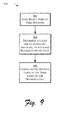
- FIG. 9 is a flow diagram depicting a procedure in an exemplary implementation in which routing table size is dynamically determined based on the available resources of the node.
- FIG. 10 is an illustration of an exemplary computing device that may be utilized to provide a node in a peer-to-peer network.
- Routing in a peer-to-peer network is described. As previously described, a smaller number of hops is desirable such that a fewer number of forwarding nodes may be utilized, thereby lowering overall bandwidth consumption. Routing techniques are described that reduce the number of hops utilized to find a resource in an ultra-large system (i.e. 1 trillion nodes), but with a low and controllable per-node maintenance budget.
- Routing tables are utilized by a node to reference other nodes in the peer-to-peer network.
- Traditional maintenance of routing tables may utilize an unacceptably large amount of hardware, software, and network resources in an ultra-large system.
- Traditional maintenance techniques for instance, utilized probing such that entries in the routing tables were updated by sending requests and receiving responses to the requests to determine whether the node referenced by the table is currently available in the system.
- the amount of hardware, software, and network resources utilized for each probe is relatively small, when this resource usage is aggregated across the entire system, the amount may become significant. Therefore, an ultra-large system may suffer a significant loss in functionality when using these traditional maintenance techniques.
- the maintenance budget utilized to maintain routing tables may be distributed over multiple segments of the resource space of the peer-to-peer network by building dense routing table entries for each segment.
- the overall maintenance budget for maintaining the routing tables may be reduced, which frees the hardware, software, and network resources of the peer-to-peer network to provide the desired functionality of routing requests and responses to the requests.
- routing tables may be maintained which utilize fewer hops in an ultra-large system without resulting in an unacceptable maintenance budget. Further discussion of dense routing entries and maintenance of routing tables may be found in relation to FIG. 3.
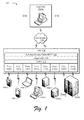
- FIG. 1 is an illustration of an exemplary implementation showing a system 100 that is configured to provide a peer-to-peer network.
- the system 100 includes a plurality of clients 102(a), where "a” can be any integer from one to "A”, which is communicatively coupled to a plurality of computing devices 104(1)-104(B) over a network 106.
- the plurality of clients 102(a) and the plurality of computing devices 104(1)-104(B) each represent a node in the network 106.
- a node may be thought of as a connection point to transmit data, such as a redistribution point that provides data to other nodes and/or an end point that is a destination and/or source of data.
- the plurality of clients 102(a) and the plurality of computing devices 104(1)-104(B) may be configured in a variety of ways.
- the clients 102(a) and computing devices 104(1)-104(B) may be configured as computers that are capable of communicating over the network 106, such as a wireless phone (e.g., computing device 104(1)), a tablet computer (e.g., computing device 104(2)), a notebook computer (e.g., computing device 104(3)), a desktop computer (e.g., computing device 104(4)), servers (e.g., computing devices 104(5)-104(6)), a mainframe computer (e.g., computing device 104(B)), and other computing devices, such as a mobile station, an entertainment appliance, a set-top box, and so forth.
- a wireless phone e.g., computing device 104(1)
- a tablet computer e.g., computing device 104(2)
- a notebook computer e.g., computing device 104(3)
- the plurality of clients 102(a) and computing devices 104(1)-104(B) may range from full resource devices with substantial memory and processor resources (e.g., personal computers, television recorders equipped with hard disk) to low-resource devices with limited memory and/or processing resources (e.g., traditional set-top boxes).
- the clients 102(a) may also relate to a person and/or entity that operate the client. In other words, client 102(a) may describe a logical client that includes a user and/or a machine.
- the network 106 is configured as a peer-to-peer network.
- a peer-to-peer network allows nodes of the network 106 to access shared resources located on each of the nodes, i.e. the plurality of clients 102(a) and the plurality of computing devices 104(1)-104(B). Examples of peer-to-peer networks, which have been known and used in the past, include the following:
- a variety of resources may be exchanged using a peer-to-peer network, such as data, processing cycles, data storage, and so on.
- the peer-to-peer network may be utilized to leverage the collective power of the plurality of clients 102(a) and the plurality of computing devices 104(1)-104(B).
- Peer-to-peer is a communications model in which each node, i.e. "member”, may communicate directly with another member and/or through a mediating computing device.
- the clients 102(a) and the computing devices 104(1)-104(B) may communicate over the network 106 by using messages, such as requests and responses.
- seven computing devices 104(1)-104(B) are illustrated, a wide variety of computing devices may be implemented in the environment.
- the plurality of clients 102(a) may also be configured as "peers", i.e. members, in the peer-to-peer network.
- the network 106 includes a distributed hash table (DHT) 108 which acts as an interface to route messages between the clients 102(a) and the plurality of computing devices 104(1)-104(B).
- the DHT 108 may be thought of as a distributed version of a hash table data structure that stores (key, value) pairs.
- the key may correspond to a file name and the value may correspond to contents of the file.
- Each peer in the network 106 e.g. computing devices 104(1)-104(B), stores a subset of (key, value) pairs.
- the DHT 108 is therefore utilized to find a node responsible for a corresponding key.
- the DHT 108 maps the key to the node to route messages between the clients 102(a) and the plurality of computing devices 104(1)-104(B).
- a variety of services may be built "on-top" of the DHT 108, such as file sharing services, archival storage services (e.g., Web archiving), databases, naming systems, service discovery, application-layer multicast, event notification, chat services, rendezvous-based communication, query and indexing, data publishing/subscriptions, and so on.
- the DHT 108 partitions resources provided by the plurality of computing devices 104(1)-104(B) into a plurality of zones 110(1)-110(8), i.e. "buckets".
- Each of the plurality of zones 110(1)-110(8) may be thought of a portion of the total resources shared in the system 100.
- the DHT 108 associates resources with keys. The key is hashed to find a particular one of the plurality of zones 110(1)-110(8) using the DHT 108.
- the plurality of zones 110(1)-110(8) may be provided in a variety of ways.
- zone 110(1) is represented pictorially in FIG. 1 as being provided by computing device 104(1).
- zones 110(2), 110(3), 110(4), 110(5), 110(6) are each provided by respective computing devices 104(2), 104(3), 104(4), 104(5), 110(6).
- a computing device may provide more than one zone, which is represented pictorially in FIG. 1 as zones 110(7), 110(8) as being provided by computing device 104(B).
- the DHT 108 is shown as employing a three-layer architecture that includes a leafset 112, a finger table 114, and a soft-state routing table 116 (SSRT).
- the leafset 112 is utilized to guarantee the integrity of the key space.
- the leafset 112 may employ consistent hashing to divide the resource space and a node's response space into one or more of the plurality of zones 110(1)-110(8) as previously described.
- the finger table 114 may be utilized to implement a prefix-based routing algorithm, such as an O (log N ) prefix routing algorithm, where " N " is the total number of nodes.
- Each node may include a finger table 114 that has entries, i.e. fingers, which point to other nodes in the system 100.
- the entries of the finger table 114 may follow a logarithmic function to reference successively "further" nodes in the system 100.
- the entries of the finger table 114 may be constructed by flipping a bit of a corresponding node's ID and then pointing to the node which keeps the resultant keys.
- Periodic beaconing may be employed for updating both the leafset 112 and finger table 114 entries, such as by using a probing mechanism.
- the leafset 112 and the finger table 114 may provide O(log N ) performance to the DHT 108.
- the SSRT 116 when the chum rate ⁇ is small (e.g., when nodes join or leave the system 100), gives a listing of the nodes that are members of the system 100. Thus, the SSRT 116 may be utilized to quickly locate a desired node.
- the construction of the SSRT 116 may be accomplished by utilizing the fingers of all the nodes in the system 100, which form a broadcast graph with adequate redundancy.
- broadcasting refers to dissemination of data in a graph in which one vertex, called the originator, distributes data to all other vertices by placing a series of calls along the edges of the graph. Once informed, other vertices aid the originator in distributing the message.
- a broadcast graph is a graph in which broadcasting can be accomplished in " ⁇ log 2 n ⁇ " time units.
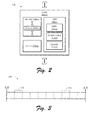
- FIG. 2 is an illustration of a system 200 in an exemplary implementation in which a plurality of nodes 202(x), where "x" can be any integer from one to "X", of a peer-to-peer network is shown in greater detail.
- Node 202(x) may be the same as or different from the nodes in the system 100 of FIG. 1, e.g. computing devices 104(1)-104(H) and clients 102(a).
- the node 202(x) is illustrated as including a corresponding DHT 108(x) having a leafset 112(x), finger table 114(x) and SSRT 116(x) which are numbered to indicate that these tables are versions of the DHT 108, leafset 112, finger table 114, and SSRT 116 of FIG. 1 for that particular node 202(x).
- the node 202(x) may monitor membership of other nodes of the leafset 112(x) through receipt of one or more events received from the respective node that describe the change in membership, such as a "join” or "leave” event.
- the node 202(x) observes a change in membership, the node 202(x) inserts one or more of a plurality of events 204(c), e.g. join or leave event, into a report 206(x).
- the report 206(x) is broadcast in parallel through each finger of the node 202(x) described by the finger table 114(x) at a predefined broadcast interval.
- Each of the plurality of nodes 202(x) may perform the same operation by building reports that describe events the node has observed and also describing events flooded from other nodes in the system 200, minus those events that have already been described by the node 202(x).
- a flooding algorithm is provided that offers adequate redundancies (O(log N )) to deliver reliable broadcast with a high propagation speed (on average O(log N )
- events may be buffered internally in a queue 208(x) if a quota is exceed.
- the DHT 108 may adaptively deal with robustness by using one or more rules. For instance, to ensure that SSRT 116(x) entries are of a high quality (e.g., the SSRT 116(x) entries describe the current membership of the system 100 of FIG. 1), "leave" events, which describe that a particular node has left the system 100, are sent out before other events, e.g. "join" events.
- system 100 is kept aware of when resources are not available from particular nodes that have left the system before being notified of when another node has joined the system 100, which is utilized to reestablish system 100 equilibrium. Further discussion of system equilibrium may be found in the "Adaptation" section.
- the event is 34 bytes and includes data describing an event type, a timestamp, an IP address and a node ID.
- the constant "4" in the equation accounts for bandwidth cost in both sending and receiving, as well as one join and one leave operation for each session.
- the DHT 108(x) may make extensive use of aggregation, which is exercised in both the temporal (e.g., batch events into reports) and spatial (e.g., interact with O log 2 N ) nodes) domains. Additionally, by utilizing broadcasting to communicate changes in membership, even though a full cluster is maintained, when there is no event to be communicated, there is little traffic in the network which results in increased network efficiency.
- the DHT 108 provides the effect of O (log b N ) routing with very large b (e.g., b equal to approximately 4,000), which does not require active probing of each of the entries.
- O log b N
- b e.g., b equal to approximately 4,000
- bandwidth consumption may be small to send and/or respond to a probe to update entries in the DHT 108
- sending and responding to a large amount of probes may result in a significant overhead when aggregated across all or a portion of the system 100 of FIG. 1.
- decreasing probing frequency may not be desirable because a miss is costly to detect, e.g. a miss may result in a random IP hops to locate the desired resource in the system.
- the performance of a b 4,000 prefix-based routing when N is equal to one trillion is replicated.
- the broadcasting budget Q is 5kb/s and the chum rate ⁇ is assumed to be 1/(3 hours). These parameters permit a full cluster of 4K size to be built utilizing the DHT 108. It should be apparent that a variety of broadcasting budgets and churn rates may be addressed by the routing techniques described herein.
- An example of a routing technique that may be utilized to deliver such performance includes two components.
- the first component involves the building of a crossbar for a sub-region, instead of the whole resource space, using one quarter of the broadcast budget, i.e. Q / 4.
- the second component is the designing of a mechanism to use four such crossbars to revolve 40 bits when routing.
- Total resource space T may be divided into t /2 i regions for some integer " i ".
- the division may be such that, on average, each region M contains approximately one thousand nodes.
- R(x) be the region that it belongs to and let beamers(x) be the subset of x's fingers that fall within R , i.e. that point to other nodes in that region R .
- the corresponding beamers collectively form a broadcast graph that covers R and has a significant degree of redundancy.
- each of these nodes may be supplied with a corresponding SSRT that covers the corresponding region R .
- the bandwidth cost may be calculated as follows: 4 ⁇ ⁇ E ⁇ M ⁇ logM.
- the bandwidth cost is about one kb/s.
- the first component is met, namely using less that Q / 4 to build a cluster that can resolve the shortest 10 base-2 finger range with one hop.
- the sub-region cluster can be regarded as a leafset of 1K nodes. For example, if a lookup key falls within this range, one hop will be sufficient to find the desired resource.
- each node may compute an average zone size z using the information of its corresponding leafset.
- the next node may then make its estimation of region R as 10 bits further than z .
- the beamers are the fingers within the region estimation.
- the boundary may be further enforced by dropping join-events sent by nodes that lie outside the region estimation.
- the SSRT of a node will not be polluted by entries from neighboring regions.
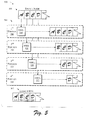
- FIG. 3 is an illustration showing a one-dimensional logical key space 300 that depicts SSRTs of several nodes in a system implemented in a peer-to-peer network.
- a first region 302 of the one-dimensional logical key space 300 may be described by an SSRT of a first one of the plurality of nodes 202(x) of FIG. 2
- a second region 304 of the one-dimensional logical key space 300 may be described by the SSRT of a second one of the plurality of nodes 202(x) of FIG. 2, and so forth.
- the dashed lines illustrated in FIG. 3 represent theoretical region division lines.
- the SSRTs are populated by entries covering a corresponding region of a corresponding node.
- the ID length of each node is 160 bits and a ten bit segment of an ID will be referred to as a "block".
- the ID may be thought of as the address of the node in the peer-to-peer network.
- Routing continues in the regional cluster by matching one bit of the address at a time through the fingers, until the destination is within the range covered by the shortest ten fingers.
- the SSRT delivers access to the resource in one hop. Effectively, these last ten fingers may be expanded into 2 10 SSRT entries to extend this access. In other words, the fingers located in other leading blocks are expanded into SSRT entries for inclusion in the same prefix-range.
- each node has, on average, 40 fingers.
- Ring 0 will be used to denote the base ring.
- the ID of a node is divided into blocks of ten bits which are named alphabetically as shown in FIG. 4. Although ten bit blocks are shown, blocks may utilize different amounts of bits. For instance, each block may have two or more bits, may have five or more bits, and so on.
- ID 404 and ID A 406 means that these four nodes, in turn, are those that share the last three blocks of ID but vary in block A in Ring 0 . Therefore, the task of expanding the 10 base-2 fingers in block A into 2 10 SSRT entries is accomplished. Similar arrangements may be performed for blocks B, C, and D (e.g. SSRT D 410). Each ring helps to build SSRT entries that cover the corresponding block.
- SSRT entries for block A are denoted as SSRT A
- SSRT entries for block B are denoted as SSRT B
- the final SSRT is a combination of the four smaller SSRTs (e.g., SSRT A , SSRT B , SSRT C , SSRT D ,) and is approximately 4K in size. Routing using the DHT may proceed in which bits are matched as aggressively as possible for proceeding through intermediate hops.
- FIG. 5 is an illustration of an exemplary implementation 500 showing routing as performed by using the SSRT table that is located on each node of the system 100 of FIG. 1.
- a lookup key 502 is utilized in conjunction with a SSRT 504 to locate a node having a particular address 506.
- the SSRT 504 includes entries that references nodes having addresses which have varying levels of similarity.
- the SSRT 504 may be composed of a plurality of portions 508, 510, 512, 514 having respective SSRT 516, 518, 520, 522 entries.
- the first portion 508 includes SSRT A 516 entries that reference each node having the different addresses that can be described in block A 524.
- the second portion 510 includes SSRT B 518 entries that reference each node having addresses that match, one to another, for address block A.
- the second portion 510 references each node having a respective different address that can be described in block B 524. In other words, all the entries in SSRT B 518 have a respective block A that matches, one to another, but has a different block B.
- the third portion 512 includes SSRT C 520 entries that reference each node having respective address blocks A and B that match, one to another.
- the third portion 512 references each node having each of different addresses that can be described in block C. Therefore, all the entries in SSRT C 520 have respective matching blocks A and B but a different block C.
- the fourth portion 514 includes SSRT D 522 entries that reference each node having matching address blocks A, B and C.
- the fourth portion 514 references each node having one of different addresses that can be described in block D.
- all the entries in SSRT D 518 have matching blocks A, B, and C but a different block D, which provides "one hop" routing to the respective node.
- each SSRT that is maintained by the respective nodes may provide describe different hierarchies of nodes having similar addresses to provide efficient routing in a peer-to-peer network.
- the SSRT 504 may be utilized to find a particular resource by examining the SSRT 504 using the lookup key 502. If blocks A 524, B 526, C 528, and D 530 of the lookup key 502 match corresponding blocks A, B, C, and D described in the SSRT D 522 entries of the SSRT 504 table, the SSRT 504 may be utilized to route the request directly to the corresponding source node 506, i.e. in one hop.
- each node includes a SSRT that may be utilized to quickly locate a node in an ultra-large system.
- FIG. 6 is an illustration of an exemplary implementation 600 showing routing as performed by using the SSRT table of FIG. 6 that is located on each node of the system 100 of FIG. 1.
- the SSRT may be constructed from a plurality of rings that reference locations of each node in a peer-to-peer network by rotating the identifier of each node.
- ring A 602 may have an SSRT A 604 having a plurality of entries.
- each entry in the SSRT A 604 has an initial three blocks (which are illustrated in FIG. 6 as "N
- the fourth block "A" in the SSRT A 604 describes each location in the system having a corresponding address for that fourth block.
- the ID i.e. address of the node in the peer-to-peer network
- the ID is "rotated”. For example, address 606 "110
- an SSRT may be constructed that reduces the amount of hops that are performed to locate a desired resource in an ultra-large system.
- routing resolution in higher blocks takes slightly more than one hop for each block, except for the destination that is within the range covered by the shortest ten fingers.
- the destination key k is random.
- addr A ( k ) be the A block of k (i.e., the ten most significant bits), therefore addr A ( k ) has 2 10 possible values.
- the 1K SSRT A (x) entries are nodes whose IDs share the last three blocks of ID( x ), but vary at block A. Because node ID is random, it is not guaranteed that the "A" blocks of SSRT A (x) entries also contain the 2 10 possible values of addr A ( k ).
- the above described problem is equivalent to dividing the complete resource space into approximately one thousand bins, and then nodes in SSRT A ( x ) as well as x itself are balls randomly dropped into these bins.
- the lookup in block A may be resolved with one hop if and only if the bin indexed by addr A ( k ) is not empty, as shown in FIG. 6.
- the space is divided into 512 bins and addr A ( k ) points to a bin that is not empty, then the nine most significant bits may be resolved using SSRT A ( x ), leaving one more hop to resolve using an ordinary "finger" from a finger table before starting to use an SSRT B of another node.
- P i be the probability that at least i bits can be resolved.
- the space is divided into 2 i bins and 2 10 balls are dropped into the space.
- Performance has been described in reference to a one trillion node system.
- Peaks in bandwidth consumption may still be encountered even when average bandwidth consumption described in the previous exemplary routing techniques conforms to the bandwidth budget Q. Therefore, as previously described in relation to FIG. 2, events may be buffered internally in the queue 208(x) of FIG. 2 until additional bandwidth becomes available.
- adaptation techniques may also be employed to control the quality of the SSRT when dynamic changes in the system occur. For example, adaptation techniques may be utilized to gracefully degrade routing performance under stress and return to normal routing performance afterwards.
- An exemplary first such adaptation technique addresses a high chum rate ⁇ that will also stabilize the system into equilibrium under a steady condition.
- This adaptation technique involves the "pruning" of redundant events that are included in reports to adaptively control broadcast traffic. The net result is a well-maintained, high quality SSRT. Further discussion of configuration of the report such that redundant events are not included may be found in relation to FIG. 8.
- An exemplary second such adaptation technique builds upon the first adaptation technique where the SSRT becomes a crossbar covering a portion of the total resource space as shown in relation to FIG. 3.
- the first and second adaptation techniques may be combined to shape the SSRT included on each node such that when combining the SSRT of each of the nodes, a multi-level architecture is obtained by combining the two optimizations.
- a two level architecture may be employed in which the first level spans an entire resource space and the second level provides regional crossbars.
- a four level architecture may be employed as described in relation to FIG. 5. With this hybrid approach, O(1) can be reached for a system having a large number of nodes and yet without exceeding the bandwidth budget Q .
- eSSRT denote a subset of SSRT entries whose state is “online.” Filtering may be utilized to ensure that the state is as accurate as possible at the expense of eSSRT size. That is to say, a low false-positive rate is achieved with a larger number of false-negative entries. The rational is that a "miss” is generally more costly than a "hit”.
- filtering may utilize a variety of rules, examples of which are shown below:
- the system will reach equilibrium automatically because the buffered events will help to prune those events received in the future.
- leave events may occupy most of the bandwidth quota at the beginning of the adaptation with any "overflow" join events being buffered.
- the buffered join events will cancel leave events, when received, thereby giving share to release join events.
- churn rate ⁇ becomes steady, the share of network and node resources used to send join and leave events will eventually be approximately equal.
- the higher the chum rate the more effective this approach will be in reducing the overall use of network resources in the peer-to-peer network.
- the buffered events will be released when the bandwidth quota becomes available again, allowing the system to weather event storms (e.g., rapid changes in membership resulting in a plurality of events being communicated at a particular point in time) and rapidly return to normal performance levels afterwards. In this way, a robust routing technique is provided.
- weather event storms e.g., rapid changes in membership resulting in a plurality of events being communicated at a particular point in time
- set-reconciliation One practical issue for any DHT routing technique that utilizes a large routing table is how to pull a returning peer's routing table(s) current, in what may be referred to as "set-reconciliation". For example, in the previously described routing techniques, an issue arises in how to obtain an up-to-date SSRT when joining the peer-to-peer network, since both the leafset and finger table of the returning node may be newly constructed each time the node joins the peer-to-peer network.
- the SSRT may be persisted in stable storage at the background, and its membership list (e.g., the entries having ⁇ ID, IP> pair of all other nodes) includes whatever a node has learned throughout its past history.
- a node that is completely new to the system may copy a SSRT at the time it first joins. Therefore, when the system has operated for a sufficient period time, the membership list set in SSRT will be generally consistent across the entire system.
- the joining node may not be aware of the state of peers recorded in its corresponding SSRT. Therefore, the joining node may reset each of the entries in the SSRT to the state of offline, and then try to learn from one or more of the existing nodes in the peer-to-peer network. For example, if the SSRTs of the two nodes are synchronized with each other, the existing node can send a vector with each bit of the vector representing the state of other peers from the existing node's SSRT.
- chum rate ⁇ is high and number of online entries is small, for instance, it is practical to copy the eSSRT. For example, it may take approximately eight seconds to transfer approximately 4K entries, each having 32 bytes over a 128kb/s link. This may not be a robust solution, however, when churn rate ⁇ is low or in an ultra-large system.
- the data may be compressed with a bloom filter to reduce the amount of bandwidth utilized to update the SSRT.
- efficient communication may be provided in ultra large systems.
- a bloom filter is a probabilistic algorithm that is used to test membership in a large set by using multiple hash functions into a single array of bits. The bloom filter, for instance, may work effectively when space/bandwidth is an issue and a small error is tolerated.
- b represents a "filter parameter”.
- For each item a set of hash functions whose range fall into [0. m ] are applied and set the corresponding bit in the m -bit vector.
- the size of an item is E bytes
- the size of the filter is 8n bits (i.e. n bytes), resulting a 1/ E compression ratio.
- E may be equal to approximately 32 bytes, and thus the resulting 1/32 compression rate is considerable.
- the first protocol applies the bloom filter over the entries that are not online. The false-positive of the bloom filter would then mean that 2% of the online nodes are recorded as offline at the receiving end.
- Accuracy may be further improved in another implementation by using an "iterative bloom filter".
- a sending node i.e. a node that sends data to update a receiving node's SSRT
- the sending node identifies the set of false positive nodes A P, and applies a supplement filter with filter parameter b .
- Both filters are then sent to the receiving node, i.e. the node requesting the data to update the SSRT.
- the number of such entries is the same as the single-level bloom filter because the error rate of bloom filter depends on the filter parameter only.
- FIG. 7 An exemplary iterative bloom filter 700 is depicted in FIG. 7.
- the iterative bloom filter 700 is depicted as including a set of three bloom filters 702(1)-702(3).
- P 704 and A 706 are the set of false-positive entries of each filter.
- N a and N p be number of offline and online nodes, respectively.
- total message size is bN a bits.
- the first filter of the iterative method has message size aN p .
- the size of A i.e. the number of false-positive entries, is N a (0.6185) a .
- a single-level bloom filter may be adopted.
- Exemplary pseudo-code for this is shown as follows: In the above set reconciliation pseudo-code, b is predefined (e.g., 8), and entries of SSRT at the receiving end all start with state offline.
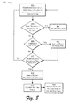
- FIG. 8 is a flow diagram illustrating a procedure 800 in an exemplary implementation in which a node forms and communicates a report that describes events received by that node that indicate a change in membership in a peer-to-peer network.
- the node receives an event indicating a change in membership in the peer-to-peer network.
- a first node may choose a random identifier ID and perform a lookup to determine if that identifier is already included in the peer-to-peer network.
- the identifier may be thought of as the address of the first node in the peer-to-peer network.
- the first node may then locate a "successor" node having the next highest identifier, denoted as ID', and notify the successor node that the first node has joined the peer-to-peer network. Notification may be performed by communicating a "join" event to the successor node.
- the procedure 800 may control maintenance costs in the peer-to-peer network by communicating no more than a predetermined number of events over a given period of time.
- a report is formed that includes the events.
- the node may aggregate events received from a plurality of nodes such that a single communication is sent having the events.
- the event may be obtained from the queue of events that were stored at block 810 and/or from other storage that has been utilized to store events received at the node.
- a routing table is examined to determine where the report is to be broadcast.
- the report is broadcast in parallel to each node referenced in the routing table.
- the routing table and the broadcast at respective blocks 816, 818 may be performed in a variety of ways.
- the routing table may be configured as the finger table 114 of FIG. 1 that utilizes a logarithmic function to describe a plurality of other nodes.
- the finger table 114 may be updated through probing the nodes that correspond to the entries.
- the "fingers" of the finger table 114 of FIG. 1 form a broadcast graph with adequate redundancy such that the report will be distributed to nodes in the region, in which, the node resides.
- the fingers may also be utilized to broadcast the report to other nodes that lie outside the region.
- Each node that receives the report may perform procedure 800 such that the events described in the report are broadcast to nodes referenced in finger tables included in each successive node.
- the events are disseminated through a broadcast graph defined by the fingers in the respective finger tables from the originating node to all other nodes by communicating the events.
- the other nodes aid the originating node in distributing the events.
- the events described in the reports may then be utilized by each of the nodes to update respective SSRTs included therein.
- the SSRTs may be utilized to reduce the number of hops needed to located desired data and reduce the amount of network bandwidth utilized to maintain the routing table.
- FIG. 9 is a flow diagram depicting a procedure 900 in an exemplary implementation in which routing table size is dynamically determined based on the available resources of the node.
- each of the nodes of the network may not have access to equal hardware, software, and/or network resources.
- computing device 104(B) may have a significant amount of hardware and software resources while computing device 104(1) may have limited hardware and software resources because computing device 104(1) is designed for portability.
- nodes may have different bandwidths for connecting to the network, such as one node may utilize a dial-up connection while another node may utilize a digital subscriber line (DSL).
- DSL digital subscriber line
- the routing tables of each of these nodes may be dynamically configured based on the available resources of the node such that the node is configured to handle routing in the peer-to-peer network in a way that is consistent with its available resources.
- a node joins a peer-to-peer network.
- the node may generate a random identifier as previously described.
- the node determines its available hardware, software, and/or network resources.
- the node may execute a software module that determines the processing and memory capabilities of the node.
- the software module when executed, may also determine the available bandwidth of the network connection, such as by determining an amount of time it takes to receive a response from a known network destination, and so on.
- the routing table of the node is configured based on the determination of resources (block 904).
- the software module may store a variety of thresholds which describe an amount of entries that may be included in the routing table based on the bandwidth of the network connection. For instance, if the node is connected via a dial-up connection, the routing table may be configured to have fewer entries than if the node was connected via a cable modem.
- the software module may compare the available hardware, software, and/or network resources of the node with other nodes in the network to arrive at a routing table size that is in accordance with other routing table sizes in the peer-to-peer network. For instance, when the node joins the peer-to-peer network the node may locate a successor node as previously described. When located, the node may query the successor node to determine a routing table size that was constructed based on the hardware, software, and/or network resources of the successor node. The node may then compare its available resources with those of the successor node and configure a routing table to have a number of entries based on the comparison. For example, if the node has greater resources than the successor node, the node may configure the routing table to have more entries than the routing table of the successor node. A variety of algorithms may be employed to compare resources and configure routing tables accordingly.
- routing table may be reconfigured at periodic intervals when the node is a member of the peer-to-peer network.
- the node may make periodic determinations of resources while the node is a member of the peer-to peer network.
- routing tables may be constructed to reflect the available resources of a corresponding node in a peer-to-peer network and may be maintained to reflect to the current available resource of the node while the node is a member of the peer-to-peer network.
- FIG. 10 shows components of a typical example of a computer environment 1000, including a computer, referred by to reference numeral 1002, that is suitable to supply a node in a peer-to-peer network.
- the computer 1002 may be the same as or different from the plurality of clients 102(a) and the plurality of computing devices 104(1)-104(B) of FIG. 1.
- the components shown in FIG. 10 are only examples, and are not intended to suggest any limitation as to the scope of the functionality of the invention; the invention is not necessarily dependent on the features shown in FIG. 10.
- various different general purpose or special purpose computing system configurations can be used.
- Examples of well known computing systems, environments, and/or configurations that may be suitable for use with the invention include, but are not limited to, personal computers, server computers, hand-held or laptop devices, multiprocessor systems, microprocessor-based systems, set top boxes, programmable consumer electronics, network PCs, network-ready devices, minicomputers, mainframe computers, distributed computing environments that include any of the above systems or devices, and the like.
- the functionality of the computers is embodied in many cases by computer-executable instructions, such as software components, that are executed by the computers.
- software components include routines, programs, objects, components, data structures, and so on, that perform particular tasks or implement particular abstract data types. Tasks might also be performed by remote processing devices that are linked through a communications network.
- software components may be located in both local and remote computer storage media.
- the instructions and/or software components are stored at different times in the various computer-readable media that are either part of the computer or that can be read by the computer.
- Programs are typically distributed, for example, on floppy disks, CD-ROMs, DVD, or some form of communication media such as a modulated signal. From there, they are installed or loaded into the secondary memory of a computer. At execution, they are loaded at least partially into the computer's primary electronic memory.
- programs and other executable program components such as the operating system are illustrated herein as discrete blocks, although it is recognized that such programs and components reside at various times in different storage components of the computer, and are executed by the data processor(s) of the computer.
- the components of computer 1002 may include, but are not limited to, a processing unit 1004, a system memory 1006, and a system bus 1008 that couples various system components including the system memory to the processing unit 1004.
- the system bus 1008 may be any of several types of bus structures including a memory bus or memory controller, a peripheral bus, and a local bus using any of a variety of bus architectures.
- Computer 1002 typically includes a variety of computer-readable media.
- Computer-readable media can be any available media that can be accessed by computer 1002 and includes both volatile and nonvolatile media, removable and non-removable media.
- Computer-readable media may comprise computer storage media and communication media.
- Computer storage media includes volatile and nonvolatile, removable and non-removable media implemented in any method or technology for storage of information such as computer-readable instructions, data structures, program modules, or other data.
- Computer storage media includes, but is not limited to, RAM, ROM, EEPROM, flash memory or other memory technology, CD-ROM, digital video discs (DVD) or other optical disk storage, magnetic cassettes, magnetic tape, magnetic disk storage or other magnetic storage devices, or any other medium which can be used to store the desired information and which can be accessed by computer 1002.
- Communication media typically embodies computer-readable instructions, data structures, program modules or other data in a modulated data signal such as a carrier wave or other transport mechanism and includes any information delivery media.
- modulated data signal means a signal that has one or more if its characteristics set or changed in such a manner as to encode information in the signal.
- communication media includes wired media such as a wired network or direct-wired connection and wireless media such as acoustic, RF, infrared and other wireless media. Combinations of any of the above should also be included within the scope of computer readable media.
- the system memory 1006 includes computer storage media in the form of volatile and/or nonvolatile memory such as read only memory (ROM) 1010 and random access memory (RAM) 1012.
- ROM read only memory
- RAM random access memory
- BIOS basic input/output system
- RAM 1012 typically contains data and/or software components that are immediately accessible to and/or presently being operated on by processing unit 1004.
- FIG. 10 illustrates operating system 1016, applications 1018, software components 1020, and program data 1022.
- the computer 1002 may also include other removable/non-removable, volatile/nonvolatile computer storage media.
- FIG. 10 illustrates a hard disk drive 1024 that reads from or writes to non-removable, nonvolatile magnetic media, a magnetic disk drive 1026 that reads from or writes to a removable, nonvolatile magnetic disk 1028, and an optical disk drive 1030 that reads from or writes to a removable, nonvolatile optical disk 1032 such as a CD ROM or other optical media.
- removable/non-removable, volatile/nonvolatile computer storage media that can be used in the exemplary operating environment include, but are not limited to, magnetic tape cassettes, flash memory cards, digital versatile disks, digital video tape, solid state RAM, solid state ROM, and the like.
- the hard disk drive 1024 is typically connected to the system bus 1008 through a non-removable memory interface such as data media interface 1034, and magnetic disk drive 1026 and optical disk drive 1030 are typically connected to the system bus 1008 by a removable memory interface.
- hard disk drive 1024 is illustrated as storing operating system 1016', applications 1018', software components 1020', and program data 1022'. Note that these components can either be the same as or different from operating system 1016, applications 1018, software components 1020, and program data 1022. Operating system 1016', applications 1018', software components 1020', and program data 1022'are given different numbers here to illustrate that, at a minimum, they are different copies.
- a user may enter commands and information into the computer 1002 through input devices such as a keyboard 1036, and pointing device (not shown), commonly referred to as a mouse, trackball, or touch pad.
- Other input devices may include source devices (such as a microphone 1038 or camera 1040 which provide streaming data), joystick, game pad, satellite dish, scanner, or the like.
- I/O input/output
- a monitor 1044 or other type of display device is also connected to the system bus 1008 via an interface, such as a video adapter 1046.
- computers may also include other rendering devices (e.g., speakers) and one or more printers, which may be connected through the I/O interface 1042.
- the computer may operate in a networked environment using logical connections to one or more remote computers, such as a remote device 1050.
- the remote device 1050 may be a personal computer, a network-ready device, a server, a router, a network PC, a peer device or other common network node, and typically includes many or all of the elements described above relative to computer 1002.
- the logical connections depicted in FIG. 10 include a local area network (LAN) 1052 and a wide area network (WAN) 1054.
- LAN local area network
- WAN wide area network
- the WAN 1054 shown in FIG. 10 is the Internet, the WAN 1054 may also include other networks.
- Such networking environments are commonplace in offices, enterprise-wide computer networks, intranets, and the like.
- the computer 1002 When used in a LAN networking environment, the computer 1002 is connected to the LAN 1052 through a network interface or adapter 1056. When used in a WAN networking environment, the computer 1002 typically includes a modem 1058 or other means for establishing communications over the Internet 1054.
- the modem 1058 which may be internal or external, may be connected to the system bus 1008 via the I/O interface 1042, or other appropriate mechanism.
- program modules depicted relative to the computer 1002, or portions thereof may be stored in the remote device 1050.
- FIG. 10 illustrates remote software components 1060 as residing on remote device 1050. It will be appreciated that the network connections shown are exemplary and other means of establishing a communications link between the computers may be used.
Applications Claiming Priority (4)
| Application Number | Priority Date | Filing Date | Title |
|---|---|---|---|
| US55937004P | 2004-03-31 | 2004-03-31 | |
| US559370P | 2004-03-31 | ||
| US10/853,933 US7730207B2 (en) | 2004-03-31 | 2004-05-25 | Routing in peer-to-peer networks |
| US853933 | 2004-05-25 |
Publications (3)
| Publication Number | Publication Date |
|---|---|
| EP1583326A2 true EP1583326A2 (de) | 2005-10-05 |
| EP1583326A3 EP1583326A3 (de) | 2006-01-25 |
| EP1583326B1 EP1583326B1 (de) | 2010-11-10 |
Family
ID=34890598
Family Applications (1)
| Application Number | Title | Priority Date | Filing Date |
|---|---|---|---|
| EP05102448A Not-in-force EP1583326B1 (de) | 2004-03-31 | 2005-03-29 | Weiterleitung in Peer-zu-Peer-Netzwerken |
Country Status (12)
| Country | Link |
|---|---|
| US (1) | US7730207B2 (de) |
| EP (1) | EP1583326B1 (de) |
| JP (1) | JP4806203B2 (de) |
| KR (1) | KR101120724B1 (de) |
| CN (1) | CN1681257B (de) |
| AT (1) | ATE488083T1 (de) |
| AU (1) | AU2005201191B2 (de) |
| BR (1) | BRPI0501178A (de) |
| CA (1) | CA2503360A1 (de) |
| DE (1) | DE602005024636D1 (de) |
| MX (1) | MXPA05003462A (de) |
| RU (1) | RU2408064C2 (de) |
Cited By (4)
| Publication number | Priority date | Publication date | Assignee | Title |
|---|---|---|---|---|
| EP2012476A1 (de) * | 2006-04-12 | 2009-01-07 | Brother Kogyo Kabushiki Kaisha | Knoteneinrichtung, ein speichersteuerprogramm enthaltendes aufzeichnungsmedium, und informationsspeicherverfahren |
| US8312065B2 (en) | 2006-04-11 | 2012-11-13 | Brother Kogyo Kabushiki Kaisha | Tree-type broadcast system, reconnection process method, node device, node process program, server device, and server process program |
| CN104079675A (zh) * | 2013-03-25 | 2014-10-01 | 联想(北京)有限公司 | 信息处理的方法、电子设备及服务器 |
| CN110688523A (zh) * | 2019-09-29 | 2020-01-14 | 深圳市网心科技有限公司 | 视频服务提供方法、装置、电子设备及存储介质 |
Families Citing this family (90)
| Publication number | Priority date | Publication date | Assignee | Title |
|---|---|---|---|---|
| US8626820B1 (en) | 2003-01-21 | 2014-01-07 | Peer Fusion, Inc. | Peer to peer code generator and decoder for digital systems |
| US9372870B1 (en) | 2003-01-21 | 2016-06-21 | Peer Fusion, Inc. | Peer to peer code generator and decoder for digital systems and cluster storage system |
| US7418454B2 (en) * | 2004-04-16 | 2008-08-26 | Microsoft Corporation | Data overlay, self-organized metadata overlay, and application level multicasting |
| US8095600B2 (en) | 2004-10-22 | 2012-01-10 | Microsoft Corporation | Inter-proximity communication within a rendezvous federation |
| US8014321B2 (en) | 2004-10-22 | 2011-09-06 | Microsoft Corporation | Rendezvousing resource requests with corresponding resources |
| US20110082928A1 (en) | 2004-10-22 | 2011-04-07 | Microsoft Corporation | Maintaining consistency within a federation infrastructure |
| US8095601B2 (en) | 2004-10-22 | 2012-01-10 | Microsoft Corporation | Inter-proximity communication within a rendezvous federation |
| US8090880B2 (en) | 2006-11-09 | 2012-01-03 | Microsoft Corporation | Data consistency within a federation infrastructure |
| US7958262B2 (en) | 2004-10-22 | 2011-06-07 | Microsoft Corporation | Allocating and reclaiming resources within a rendezvous federation |
| US8392515B2 (en) | 2004-10-22 | 2013-03-05 | Microsoft Corporation | Subfederation creation and maintenance in a federation infrastructure |
| US8549180B2 (en) | 2004-10-22 | 2013-10-01 | Microsoft Corporation | Optimizing access to federation infrastructure-based resources |
| US7656810B2 (en) * | 2005-03-25 | 2010-02-02 | Microsoft Corporation | System and method for monitoring and reacting to peer-to-peer network metrics |
| US7643458B1 (en) * | 2005-05-25 | 2010-01-05 | Hewlett-Packard Development Company, L.P. | Communicating between wireless communities |
| JP2007027996A (ja) * | 2005-07-13 | 2007-02-01 | Konica Minolta Holdings Inc | ネットワークにおける論理接続方法および情報処理装置 |
| JP4544072B2 (ja) * | 2005-07-20 | 2010-09-15 | ブラザー工業株式会社 | ノード装置、コンピュータプログラム、情報配信システム、及びネットワーク参加方法 |
| US8055788B1 (en) * | 2005-11-21 | 2011-11-08 | Hong Kong University Of Science And Technology | Efficient person search mechanism in peer-to-peer networks |
| US7468952B2 (en) * | 2005-11-29 | 2008-12-23 | Sony Computer Entertainment Inc. | Broadcast messaging in peer to peer overlay network |
| US8904456B2 (en) | 2006-02-13 | 2014-12-02 | Tvu Networks Corporation | Methods, apparatus, and systems for providing media content over a communications network |
| US20070233832A1 (en) * | 2006-03-30 | 2007-10-04 | Matsushita Electric Industrial Co., Ltd. | Method of distributed hash table node ID collision detection |
| JP4692355B2 (ja) * | 2006-03-30 | 2011-06-01 | ブラザー工業株式会社 | 情報通信システム、情報通信方法、情報通信システムに含まれるノード装置および情報処理プログラム |
| JP2007280303A (ja) * | 2006-04-11 | 2007-10-25 | Brother Ind Ltd | 情報通信システム、コンテンツカタログ情報配信方法、及びノード装置等 |
| US20070255823A1 (en) * | 2006-05-01 | 2007-11-01 | International Business Machines Corporation | Method for low-overhead message tracking in a distributed messaging system |
| JP4769647B2 (ja) * | 2006-06-23 | 2011-09-07 | キヤノン株式会社 | 通信システム、通信装置、通信装置の通信方法、並びにコンピュータプログラム |
| JP4732972B2 (ja) | 2006-06-30 | 2011-07-27 | 株式会社エヌ・ティ・ティ・ドコモ | アドホックネットワーク、ノード、経路制御方法、及び経路制御プログラム |
| US20080059631A1 (en) * | 2006-07-07 | 2008-03-06 | Voddler, Inc. | Push-Pull Based Content Delivery System |
| CA2594716C (en) * | 2006-07-26 | 2013-10-01 | V V S Virtual Video Systems (Canada) Inc. | Video and multimedia distribution system |
| WO2008040092A1 (en) * | 2006-10-05 | 2008-04-10 | National Ict Australia Limited | Decentralised multi-user online environment |
| KR100810351B1 (ko) * | 2006-11-15 | 2008-03-04 | 재단법인서울대학교산학협력재단 | 통신 시스템에서 채널 프루빙 시스템 및 방법 |
| US20080159266A1 (en) * | 2006-12-30 | 2008-07-03 | Arcsoft (Shanghai) Technology Company, Ltd | Determining Pairings of Telephone Numbers and IP Addresses from Caching and Peer-To-Peer Lookup |
| US20080198754A1 (en) * | 2007-02-20 | 2008-08-21 | At&T Knowledge Ventures, Lp | Method and system for testing a communication network |
| US7984158B2 (en) * | 2007-03-20 | 2011-07-19 | Microsoft Corporation | Web service for coordinating actions of clients |
| US8213432B2 (en) * | 2007-03-30 | 2012-07-03 | Pioneer Corporation | Network configuration investigating device, network configuration investigating program, network configuration management method, and network configuration management system |
| FR2915044B1 (fr) * | 2007-04-16 | 2009-09-18 | France Telecom | Procede de determination de la dynamique d'un reseau logique |
| US20080307436A1 (en) * | 2007-06-06 | 2008-12-11 | Microsoft Corporation | Distributed publish-subscribe event system with routing of published events according to routing tables updated during a subscription process |
| US8238237B2 (en) | 2007-06-18 | 2012-08-07 | Sony Computer Entertainment Inc. | Load balancing distribution of data to multiple recipients on a peer-to-peer network |
| US8494007B2 (en) * | 2007-07-10 | 2013-07-23 | Qualcomm Incorporated | Coding methods of communicating identifiers in peer discovery in a peer-to-peer network |
| US8520704B2 (en) * | 2007-07-10 | 2013-08-27 | Qualcomm Incorporated | Coding methods of communicating identifiers in peer discovery in a peer-to-peer network |
| US7961708B2 (en) * | 2007-07-10 | 2011-06-14 | Qualcomm Incorporated | Coding methods of communicating identifiers in peer discovery in a peer-to-peer network |
| US8630281B2 (en) * | 2007-07-10 | 2014-01-14 | Qualcomm Incorporated | Coding methods of communicating identifiers in peer discovery in a peer-to-peer network |
| US9848372B2 (en) * | 2007-07-10 | 2017-12-19 | Qualcomm Incorporated | Coding Methods of communicating identifiers in peer discovery in a peer-to-peer network |
| CN101399746B (zh) * | 2007-09-26 | 2011-03-16 | 华为技术有限公司 | 报文路由方法、系统、设备和选择备份资源的方法、系统 |
| CN101442479B (zh) * | 2007-11-22 | 2011-03-30 | 华为技术有限公司 | P2p对等网络中节点失效后的路由更新方法、设备及系统 |
| CN101965716A (zh) * | 2008-01-10 | 2011-02-02 | 惠普开发有限公司 | 多路对等媒体流传送 |
| US8775817B2 (en) * | 2008-05-12 | 2014-07-08 | Microsoft Corporation | Application-configurable distributed hash table framework |
| US8996726B2 (en) | 2008-06-19 | 2015-03-31 | Qualcomm Incorporated | Methods and apparatus for event distribution and routing in peer-to-peer overlay networks |
| ATE551818T1 (de) * | 2008-06-27 | 2012-04-15 | Alcatel Lucent | Verfahren zur bereitstellung einer nachfolgerliste |
| US7990973B2 (en) * | 2008-08-13 | 2011-08-02 | Alcatel-Lucent Usa Inc. | Hash functions for applications such as network address lookup |
| US8018940B2 (en) * | 2008-08-13 | 2011-09-13 | Alcatel Lucent | Network address lookup based on bloom filters |
| US9240927B2 (en) * | 2009-02-26 | 2016-01-19 | Qualcomm Incorporated | Methods and apparatus for enhanced overlay state maintenance |
| US20100228701A1 (en) * | 2009-03-06 | 2010-09-09 | Microsoft Corporation | Updating bloom filters |
| CN101534309B (zh) | 2009-04-14 | 2013-03-13 | 华为技术有限公司 | 节点注册方法、路由更新方法、通讯系统以及相关设备 |
| US8549175B2 (en) * | 2009-06-09 | 2013-10-01 | Qualcomm Incorporated | Methods and apparatus for adaptively scheduling a finger stabilization algorithm |
| CN101997759B (zh) * | 2009-08-10 | 2013-06-05 | 中兴通讯股份有限公司 | 一种业务实现方法及业务系统 |
| US9009299B2 (en) * | 2010-01-07 | 2015-04-14 | Polytechnic Institute Of New York University | Method and apparatus for identifying members of a peer-to-peer botnet |
| US9832104B2 (en) | 2010-02-11 | 2017-11-28 | Microsoft Technology Licensing, Llc | Reliable broadcast in a federation of nodes |
| US9055082B2 (en) * | 2010-08-25 | 2015-06-09 | Alcatel Lucent | Peer to peer localization for content in a distributed hash table |
| US8392368B1 (en) | 2010-08-27 | 2013-03-05 | Disney Enterprises, Inc. | System and method for distributing and accessing files in a distributed storage system |
| US8290919B1 (en) * | 2010-08-27 | 2012-10-16 | Disney Enterprises, Inc. | System and method for distributing and accessing files in a distributed storage system |
| US8768981B1 (en) | 2010-08-27 | 2014-07-01 | Disney Enterprises, Inc. | System and method for distributing and accessing files in a distributed storage system |
| US8934492B1 (en) | 2010-09-28 | 2015-01-13 | Adtran, Inc. | Network systems and methods for efficiently dropping packets carried by virtual circuits |
| JP5666719B2 (ja) * | 2010-12-20 | 2015-02-12 | テレフオンアクチーボラゲット エル エム エリクソン(パブル) | ピアツーピア・ネットワークにおける検索 |
| JP5387596B2 (ja) * | 2011-02-28 | 2014-01-15 | ブラザー工業株式会社 | 情報通信システム、情報通信方法、情報処理装置およびプログラム |
| US9667713B2 (en) * | 2011-03-21 | 2017-05-30 | Apple Inc. | Apparatus and method for managing peer-to-peer connections between different service providers |
| TWI571166B (zh) * | 2012-01-13 | 2017-02-11 | 蘋果公司 | 在點對點網路環境中同步站台之選擇 |
| US8886827B2 (en) * | 2012-02-13 | 2014-11-11 | Juniper Networks, Inc. | Flow cache mechanism for performing packet flow lookups in a network device |
| EP2639708B8 (de) * | 2012-03-13 | 2019-07-31 | Ricoh Company, Ltd. | Verfahren und System zum Speichern und Abrufen von Daten |
| FR2994003A1 (fr) * | 2012-07-26 | 2014-01-31 | Jean Louis Guenego | Dispositif informatique de stockage de donnees privees totalement distribue en environnement hostile |
| KR102110524B1 (ko) * | 2013-03-20 | 2020-05-28 | 삼성전자주식회사 | 컨텐츠 중심 네트워크에서 블룸 필터를 이용하여 라우팅을 수행하는 노드 및 그 방법 |
| JP6034754B2 (ja) * | 2013-06-12 | 2016-11-30 | 株式会社東芝 | サーバ装置、通信システム、およびデータ発行方法 |
| RU2538323C1 (ru) * | 2013-06-28 | 2015-01-10 | Федеральное государственное бюджетное образовательное учреждение высшего профессионального образования "Южно-Российский государственный университет экономики и сервиса" (ФГБОУ ВПО "ЮРГУЭС") | Способ организации таблицы фильтрации межсетевого коммутатора и устройство для его реализации |
| JP6291573B2 (ja) | 2013-07-02 | 2018-03-14 | コンヴィーダ ワイヤレス, エルエルシー | セマンティクス公表および発見のための機構 |
| WO2015029592A1 (ja) * | 2013-08-27 | 2015-03-05 | ソニー株式会社 | 情報処理装置および情報処理方法 |
| US9917727B2 (en) | 2014-06-03 | 2018-03-13 | Nicira, Inc. | Consistent hashing for network traffic dispatching |
| US9940356B2 (en) * | 2014-07-31 | 2018-04-10 | International Business Machines Corporation | Efficient join-filters for parallel processing |
| US10163420B2 (en) | 2014-10-10 | 2018-12-25 | DimensionalMechanics, Inc. | System, apparatus and methods for adaptive data transport and optimization of application execution |
| US10062354B2 (en) | 2014-10-10 | 2018-08-28 | DimensionalMechanics, Inc. | System and methods for creating virtual environments |
| US10277686B2 (en) * | 2015-07-29 | 2019-04-30 | Cisco Technology, Inc. | Service discovery optimization in a network based on bloom filter |
| EP3449379B1 (de) * | 2016-04-28 | 2021-10-06 | Kandou Labs S.A. | Vektorsignalisierungscodes für dichtgeleitete drahtgruppen |
| US10417094B1 (en) | 2016-07-13 | 2019-09-17 | Peer Fusion, Inc. | Hyper storage cluster |
| US11451475B2 (en) | 2019-12-19 | 2022-09-20 | Huawei Technologies Co., Ltd. | Packet forwarding based on geometric location |
| US11329717B2 (en) | 2020-05-26 | 2022-05-10 | Huawei Technologies Co., Ltd. | Packet forwarding incorporating partial sorting of path costs or utilities |
| US11374852B2 (en) | 2020-05-29 | 2022-06-28 | Huawei Technologies Co., Ltd. | Piecewise shortest path first routing |
| US11438823B2 (en) | 2020-05-29 | 2022-09-06 | Huawei Technologies Co., Ltd. | Orthodromic routing |
| KR102503028B1 (ko) * | 2020-11-27 | 2023-02-23 | (주)유미테크 | 블룸필터를 이용한 분산식별자 검색 방법 |
| US11374652B1 (en) | 2020-12-10 | 2022-06-28 | Huawei Technologies Co., Ltd. | Method and apparatus for limited flooding and network routing region membership management |
| US11909627B2 (en) | 2021-01-04 | 2024-02-20 | Huawei Technologies Co., Ltd. | Method and apparatus for managing network status information using multiple degree of precision graph |
| US11601780B2 (en) | 2021-01-05 | 2023-03-07 | Huawei Technologies Co., Ltd. | Method and apparatus for propagating network status updates using directional tracking |
| US11476925B2 (en) | 2021-02-04 | 2022-10-18 | Huawei Technologies Co., Ltd. | Method and apparatus for limited flooding in networks using transit nodes |
| US11799761B2 (en) | 2022-01-07 | 2023-10-24 | Vmware, Inc. | Scaling edge services with minimal disruption |
| US11888747B2 (en) | 2022-01-12 | 2024-01-30 | VMware LLC | Probabilistic filters for use in network forwarding and services |
Family Cites Families (30)
| Publication number | Priority date | Publication date | Assignee | Title |
|---|---|---|---|---|
| EP1691315A1 (de) * | 1994-10-27 | 2006-08-16 | Intarsia Software LLC | Verwaltungssystem für Datenurheberrecht |
| FR2749681B1 (fr) * | 1996-06-10 | 1998-07-10 | Bull Sa | Circuit pour transborder des donnees entre memoires distantes et calculateur comprenant un tel circuit |
| US5796830A (en) * | 1996-07-29 | 1998-08-18 | International Business Machines Corporation | Interoperable cryptographic key recovery system |
| US5784463A (en) * | 1996-12-04 | 1998-07-21 | V-One Corporation | Token distribution, registration, and dynamic configuration of user entitlement for an application level security system and method |
| US6236729B1 (en) * | 1997-06-06 | 2001-05-22 | Hitachi, Ltd. | Key recovery method and system |
| US6108699A (en) * | 1997-06-27 | 2000-08-22 | Sun Microsystems, Inc. | System and method for modifying membership in a clustered distributed computer system and updating system configuration |
| US6185308B1 (en) * | 1997-07-07 | 2001-02-06 | Fujitsu Limited | Key recovery system |
| US5987376A (en) * | 1997-07-16 | 1999-11-16 | Microsoft Corporation | System and method for the distribution and synchronization of data and state information between clients in a distributed processing system |
| TW374965B (en) * | 1998-03-17 | 1999-11-21 | Winbond Electronics Corp | Method of processing of transmission of confidential data and the network system |
| JPH11275068A (ja) * | 1998-03-20 | 1999-10-08 | Fujitsu Ltd | 鍵管理サーバ、チャットシステムの端末装置、チャットシステム及び記録媒体 |
| US6311270B1 (en) * | 1998-09-14 | 2001-10-30 | International Business Machines Corporation | Method and apparatus for securing communication utilizing a security processor |
| US6038322A (en) * | 1998-10-20 | 2000-03-14 | Cisco Technology, Inc. | Group key distribution |
| US6154543A (en) * | 1998-11-25 | 2000-11-28 | Hush Communications Anguilla, Inc. | Public key cryptosystem with roaming user capability |
| US6367010B1 (en) * | 1999-07-02 | 2002-04-02 | Postx Corporation | Method for generating secure symmetric encryption and decryption |
| EP1128597B1 (de) * | 2000-02-22 | 2004-07-07 | Telefonaktiebolaget LM Ericsson (publ) | Verfahren und Vorrichtung in einem Kommunikationsnetzwerk |
| JP2002077189A (ja) * | 2000-08-31 | 2002-03-15 | Nec Eng Ltd | Atm交換網における重要呼制御方式 |
| JP2002108910A (ja) * | 2000-09-27 | 2002-04-12 | Nec Soft Ltd | 暗号化ファイルシステム及び暗号化ファイル検索方法並びにコンピュータ可読記録媒体 |
| US20020090089A1 (en) * | 2001-01-05 | 2002-07-11 | Steven Branigan | Methods and apparatus for secure wireless networking |
| JP3613185B2 (ja) * | 2001-02-16 | 2005-01-26 | 日本電信電話株式会社 | 無線ノード及びそのパケット経路探索方法 |
| JP2002271312A (ja) * | 2001-03-14 | 2002-09-20 | Hitachi Ltd | 公開鍵管理方法 |
| US7054867B2 (en) * | 2001-09-18 | 2006-05-30 | Skyris Networks, Inc. | Systems, methods and programming for routing and indexing globally addressable objects and associated business models |
| US7305556B2 (en) * | 2001-12-05 | 2007-12-04 | Canon Kabushiki Kaisha | Secure printing with authenticated printer key |
| US20030217263A1 (en) * | 2002-03-21 | 2003-11-20 | Tsutomu Sakai | System and method for secure real-time digital transmission |
| US7142524B2 (en) * | 2002-05-01 | 2006-11-28 | Meshnetworks, Inc. | System and method for using an ad-hoc routing algorithm based on activity detection in an ad-hoc network |
| CN1160911C (zh) * | 2002-09-06 | 2004-08-04 | 联想(北京)有限公司 | 家庭主干网中实现设备间动态组网与资源共享的方法 |
| US7613796B2 (en) * | 2002-09-11 | 2009-11-03 | Microsoft Corporation | System and method for creating improved overlay network with an efficient distributed data structure |
| US7603481B2 (en) * | 2002-10-31 | 2009-10-13 | Novell, Inc. | Dynamic routing through a content distribution network |
| US8499086B2 (en) * | 2003-01-21 | 2013-07-30 | Dell Products L.P. | Client load distribution |
| US20050015511A1 (en) * | 2003-07-02 | 2005-01-20 | Nec Laboratories America, Inc. | Accelerated large data distribution in overlay networks |
| US20050219929A1 (en) | 2004-03-30 | 2005-10-06 | Navas Julio C | Method and apparatus achieving memory and transmission overhead reductions in a content routing network |
-
2004
- 2004-05-25 US US10/853,933 patent/US7730207B2/en not_active Expired - Fee Related
-
2005
- 2005-03-18 AU AU2005201191A patent/AU2005201191B2/en not_active Ceased
- 2005-03-29 EP EP05102448A patent/EP1583326B1/de not_active Not-in-force
- 2005-03-29 AT AT05102448T patent/ATE488083T1/de not_active IP Right Cessation
- 2005-03-29 DE DE602005024636T patent/DE602005024636D1/de active Active
- 2005-03-29 JP JP2005094739A patent/JP4806203B2/ja not_active Expired - Fee Related
- 2005-03-30 CA CA002503360A patent/CA2503360A1/en not_active Abandoned
- 2005-03-30 RU RU2005109223/08A patent/RU2408064C2/ru not_active IP Right Cessation
- 2005-03-31 KR KR1020050026940A patent/KR101120724B1/ko not_active IP Right Cessation
- 2005-03-31 CN CN2005100637523A patent/CN1681257B/zh not_active Expired - Fee Related
- 2005-03-31 MX MXPA05003462A patent/MXPA05003462A/es active IP Right Grant
- 2005-03-31 BR BR0501178-7A patent/BRPI0501178A/pt not_active IP Right Cessation
Non-Patent Citations (1)
| Title |
|---|
| None |
Cited By (9)
| Publication number | Priority date | Publication date | Assignee | Title |
|---|---|---|---|---|
| US8312065B2 (en) | 2006-04-11 | 2012-11-13 | Brother Kogyo Kabushiki Kaisha | Tree-type broadcast system, reconnection process method, node device, node process program, server device, and server process program |
| EP2012476A1 (de) * | 2006-04-12 | 2009-01-07 | Brother Kogyo Kabushiki Kaisha | Knoteneinrichtung, ein speichersteuerprogramm enthaltendes aufzeichnungsmedium, und informationsspeicherverfahren |
| US20090052349A1 (en) * | 2006-04-12 | 2009-02-26 | Brother Kogyo Kabushiki Kaisha | Node device, recording medium where storage control program is recorded, and information storing method |
| EP2012476A4 (de) * | 2006-04-12 | 2009-12-30 | Brother Ind Ltd | Knoteneinrichtung, ein speichersteuerprogramm enthaltendes aufzeichnungsmedium, und informationsspeicherverfahren |
| EP2012476B1 (de) * | 2006-04-12 | 2012-02-29 | Brother Kogyo Kabushiki Kaisha | Knoteneinrichtung, aufzeichnungsmedium, auf dem ein speichersteuerprogramm aufgezeichnet ist, und informationsspeicherverfahren |
| US8654678B2 (en) | 2006-04-12 | 2014-02-18 | Brother Kogyo Kabushiki Kaisha | Node device, recording medium where storage control program is recorded, and information storing method |
| CN104079675A (zh) * | 2013-03-25 | 2014-10-01 | 联想(北京)有限公司 | 信息处理的方法、电子设备及服务器 |
| CN104079675B (zh) * | 2013-03-25 | 2017-12-29 | 联想(北京)有限公司 | 信息处理的方法、电子设备及服务器 |
| CN110688523A (zh) * | 2019-09-29 | 2020-01-14 | 深圳市网心科技有限公司 | 视频服务提供方法、装置、电子设备及存储介质 |
Also Published As
| Publication number | Publication date |
|---|---|
| RU2005109223A (ru) | 2006-10-10 |
| EP1583326B1 (de) | 2010-11-10 |
| CN1681257B (zh) | 2011-06-08 |
| US20050223102A1 (en) | 2005-10-06 |
| MXPA05003462A (es) | 2005-11-23 |
| CA2503360A1 (en) | 2005-09-30 |
| US7730207B2 (en) | 2010-06-01 |
| KR101120724B1 (ko) | 2012-03-23 |
| ATE488083T1 (de) | 2010-11-15 |
| AU2005201191A1 (en) | 2005-10-20 |
| CN1681257A (zh) | 2005-10-12 |
| KR20060045065A (ko) | 2006-05-16 |
| EP1583326A3 (de) | 2006-01-25 |
| BRPI0501178A (pt) | 2005-11-01 |
| JP4806203B2 (ja) | 2011-11-02 |
| DE602005024636D1 (de) | 2010-12-23 |
| RU2408064C2 (ru) | 2010-12-27 |
| AU2005201191B2 (en) | 2009-08-27 |
| JP2005323346A (ja) | 2005-11-17 |
Similar Documents
| Publication | Publication Date | Title |
|---|---|---|
| US7730207B2 (en) | Routing in peer-to-peer networks | |
| Lua et al. | A survey and comparison of peer-to-peer overlay network schemes | |
| EP2171607B1 (de) | Lastausgleichsverteilung von daten an mehrere empfänger in einem peer-to-peer-netzwerk | |
| Fraigniaud et al. | D2B: A de Bruijn based content-addressable network | |
| Chawathe et al. | Making gnutella-like p2p systems scalable | |
| JP2009089369A (ja) | 階層的ピアツーピア・ネットワークの最適運用 | |
| CN111046065A (zh) | 可扩展的高性能分布式查询处理方法及装置 | |
| Shen et al. | A proximity-aware interest-clustered P2P file sharing system | |
| Bertier et al. | D2HT: the best of both worlds, Integrating RPS and DHT | |
| JP4533923B2 (ja) | 階層型ピアツーピアシステムにおける負荷バランシング機能を有するスーパーピア及び該スーパーピアを動作させる方法 | |
| Han et al. | A hybrid P2P overlay network for high efficient search | |
| Moustakas et al. | Alleviating the topology mismatch problem in distributed overlay networks: A survey | |
| Liu et al. | From client-server to p2p networking | |
| Chan et al. | Characterizing Chord, Kelips and Tapestry algorithms in P2P streaming applications over wireless network | |
| Lua et al. | ASurvey AND COMPARISON OF PEER-TO-PEER OVERLAY NETWORK SCHEMES | |
| Chan et al. | Malugo: A peer-to-peer storage system | |
| Lu et al. | A scalable P2P overlay based on arrangement graph with minimized overhead | |
| Watanabe et al. | A superpeer-based two-layer P2P overlay network with the CBF strategy | |
| Lu et al. | Design and analysis of arrangement graph-based overlay systems for information sharing | |
| Zheng et al. | Peer-to-peer: A technique perspective | |
| Iwamaru et al. | Introducing group participation support into P2P web caching systems | |
| Ktari et al. | Exploiting power-law node degree distribution in chord overlays | |
| Huang et al. | Research of replication mechanism in P2P network | |
| Liu et al. | Investigation of research towards efficient social peer-to-peer networks | |
| Chang et al. | A distributed P2P network based on increasing reliability and scalability for internet applications |
Legal Events
| Date | Code | Title | Description |
|---|---|---|---|
| PUAI | Public reference made under article 153(3) epc to a published international application that has entered the european phase |
Free format text: ORIGINAL CODE: 0009012 |
|
| AK | Designated contracting states |
Kind code of ref document: A2 Designated state(s): AT BE BG CH CY CZ DE DK EE ES FI FR GB GR HU IE IS IT LI LT LU MC NL PL PT RO SE SI SK TR |
|
| AX | Request for extension of the european patent |
Extension state: AL BA HR LV MK YU |
|
| PUAL | Search report despatched |
Free format text: ORIGINAL CODE: 0009013 |
|
| AK | Designated contracting states |
Kind code of ref document: A3 Designated state(s): AT BE BG CH CY CZ DE DK EE ES FI FR GB GR HU IE IS IT LI LT LU MC NL PL PT RO SE SI SK TR |
|
| AX | Request for extension of the european patent |
Extension state: AL BA HR LV MK YU |
|
| 17P | Request for examination filed |
Effective date: 20060719 |
|
| AKX | Designation fees paid |
Designated state(s): AT BE BG CH CY CZ DE DK EE ES FI FR GB GR HU IE IS IT LI LT LU MC NL PL PT RO SE SI SK TR |
|
| 17Q | First examination report despatched |
Effective date: 20070509 |
|
| GRAP | Despatch of communication of intention to grant a patent |
Free format text: ORIGINAL CODE: EPIDOSNIGR1 |
|
| GRAC | Information related to communication of intention to grant a patent modified |
Free format text: ORIGINAL CODE: EPIDOSCIGR1 |
|
| GRAS | Grant fee paid |
Free format text: ORIGINAL CODE: EPIDOSNIGR3 |
|
| GRAA | (expected) grant |
Free format text: ORIGINAL CODE: 0009210 |
|
| AK | Designated contracting states |
Kind code of ref document: B1 Designated state(s): AT BE BG CH CY CZ DE DK EE ES FI FR GB GR HU IE IS IT LI LT LU MC NL PL PT RO SE SI SK TR |
|
| REG | Reference to a national code |
Ref country code: GB Ref legal event code: FG4D |
|
| REG | Reference to a national code |
Ref country code: CH Ref legal event code: EP |
|
| REG | Reference to a national code |
Ref country code: IE Ref legal event code: FG4D |
|
| REF | Corresponds to: |
Ref document number: 602005024636 Country of ref document: DE Date of ref document: 20101223 Kind code of ref document: P |
|
| REG | Reference to a national code |
Ref country code: NL Ref legal event code: VDEP Effective date: 20101110 |
|
| LTIE | Lt: invalidation of european patent or patent extension |
Effective date: 20101110 |
|
| PG25 | Lapsed in a contracting state [announced via postgrant information from national office to epo] |
Ref country code: LT Free format text: LAPSE BECAUSE OF FAILURE TO SUBMIT A TRANSLATION OF THE DESCRIPTION OR TO PAY THE FEE WITHIN THE PRESCRIBED TIME-LIMIT Effective date: 20101110 |
|
| PG25 | Lapsed in a contracting state [announced via postgrant information from national office to epo] |
Ref country code: SI Free format text: LAPSE BECAUSE OF FAILURE TO SUBMIT A TRANSLATION OF THE DESCRIPTION OR TO PAY THE FEE WITHIN THE PRESCRIBED TIME-LIMIT Effective date: 20101110 Ref country code: AT Free format text: LAPSE BECAUSE OF FAILURE TO SUBMIT A TRANSLATION OF THE DESCRIPTION OR TO PAY THE FEE WITHIN THE PRESCRIBED TIME-LIMIT Effective date: 20101110 Ref country code: FI Free format text: LAPSE BECAUSE OF FAILURE TO SUBMIT A TRANSLATION OF THE DESCRIPTION OR TO PAY THE FEE WITHIN THE PRESCRIBED TIME-LIMIT Effective date: 20101110 Ref country code: CY Free format text: LAPSE BECAUSE OF FAILURE TO SUBMIT A TRANSLATION OF THE DESCRIPTION OR TO PAY THE FEE WITHIN THE PRESCRIBED TIME-LIMIT Effective date: 20101110 Ref country code: NL Free format text: LAPSE BECAUSE OF FAILURE TO SUBMIT A TRANSLATION OF THE DESCRIPTION OR TO PAY THE FEE WITHIN THE PRESCRIBED TIME-LIMIT Effective date: 20101110 Ref country code: BG Free format text: LAPSE BECAUSE OF FAILURE TO SUBMIT A TRANSLATION OF THE DESCRIPTION OR TO PAY THE FEE WITHIN THE PRESCRIBED TIME-LIMIT Effective date: 20110210 Ref country code: SE Free format text: LAPSE BECAUSE OF FAILURE TO SUBMIT A TRANSLATION OF THE DESCRIPTION OR TO PAY THE FEE WITHIN THE PRESCRIBED TIME-LIMIT Effective date: 20101110 Ref country code: IS Free format text: LAPSE BECAUSE OF FAILURE TO SUBMIT A TRANSLATION OF THE DESCRIPTION OR TO PAY THE FEE WITHIN THE PRESCRIBED TIME-LIMIT Effective date: 20110310 Ref country code: PT Free format text: LAPSE BECAUSE OF FAILURE TO SUBMIT A TRANSLATION OF THE DESCRIPTION OR TO PAY THE FEE WITHIN THE PRESCRIBED TIME-LIMIT Effective date: 20110310 |
|
| PG25 | Lapsed in a contracting state [announced via postgrant information from national office to epo] |
Ref country code: GR Free format text: LAPSE BECAUSE OF FAILURE TO SUBMIT A TRANSLATION OF THE DESCRIPTION OR TO PAY THE FEE WITHIN THE PRESCRIBED TIME-LIMIT Effective date: 20110211 |
|
| PG25 | Lapsed in a contracting state [announced via postgrant information from national office to epo] |
Ref country code: EE Free format text: LAPSE BECAUSE OF FAILURE TO SUBMIT A TRANSLATION OF THE DESCRIPTION OR TO PAY THE FEE WITHIN THE PRESCRIBED TIME-LIMIT Effective date: 20101110 Ref country code: BE Free format text: LAPSE BECAUSE OF FAILURE TO SUBMIT A TRANSLATION OF THE DESCRIPTION OR TO PAY THE FEE WITHIN THE PRESCRIBED TIME-LIMIT Effective date: 20101110 Ref country code: CZ Free format text: LAPSE BECAUSE OF FAILURE TO SUBMIT A TRANSLATION OF THE DESCRIPTION OR TO PAY THE FEE WITHIN THE PRESCRIBED TIME-LIMIT Effective date: 20101110 Ref country code: ES Free format text: LAPSE BECAUSE OF FAILURE TO SUBMIT A TRANSLATION OF THE DESCRIPTION OR TO PAY THE FEE WITHIN THE PRESCRIBED TIME-LIMIT Effective date: 20110221 |
|
| PG25 | Lapsed in a contracting state [announced via postgrant information from national office to epo] |
Ref country code: PL Free format text: LAPSE BECAUSE OF FAILURE TO SUBMIT A TRANSLATION OF THE DESCRIPTION OR TO PAY THE FEE WITHIN THE PRESCRIBED TIME-LIMIT Effective date: 20101110 Ref country code: SK Free format text: LAPSE BECAUSE OF FAILURE TO SUBMIT A TRANSLATION OF THE DESCRIPTION OR TO PAY THE FEE WITHIN THE PRESCRIBED TIME-LIMIT Effective date: 20101110 Ref country code: DK Free format text: LAPSE BECAUSE OF FAILURE TO SUBMIT A TRANSLATION OF THE DESCRIPTION OR TO PAY THE FEE WITHIN THE PRESCRIBED TIME-LIMIT Effective date: 20101110 Ref country code: RO Free format text: LAPSE BECAUSE OF FAILURE TO SUBMIT A TRANSLATION OF THE DESCRIPTION OR TO PAY THE FEE WITHIN THE PRESCRIBED TIME-LIMIT Effective date: 20101110 |
|
| PLBE | No opposition filed within time limit |
Free format text: ORIGINAL CODE: 0009261 |
|
| STAA | Information on the status of an ep patent application or granted ep patent |
Free format text: STATUS: NO OPPOSITION FILED WITHIN TIME LIMIT |
|
| 26N | No opposition filed |
Effective date: 20110811 |
|
| PG25 | Lapsed in a contracting state [announced via postgrant information from national office to epo] |
Ref country code: MC Free format text: LAPSE BECAUSE OF NON-PAYMENT OF DUE FEES Effective date: 20110331 |
|
| REG | Reference to a national code |
Ref country code: CH Ref legal event code: PL |
|
| REG | Reference to a national code |
Ref country code: DE Ref legal event code: R097 Ref document number: 602005024636 Country of ref document: DE Effective date: 20110811 |
|
| REG | Reference to a national code |
Ref country code: IE Ref legal event code: MM4A |
|
| PG25 | Lapsed in a contracting state [announced via postgrant information from national office to epo] |
Ref country code: CH Free format text: LAPSE BECAUSE OF NON-PAYMENT OF DUE FEES Effective date: 20110331 Ref country code: LI Free format text: LAPSE BECAUSE OF NON-PAYMENT OF DUE FEES Effective date: 20110331 Ref country code: IE Free format text: LAPSE BECAUSE OF NON-PAYMENT OF DUE FEES Effective date: 20110329 |
|
| PGFP | Annual fee paid to national office [announced via postgrant information from national office to epo] |
Ref country code: IT Payment date: 20120321 Year of fee payment: 8 |
|
| PGFP | Annual fee paid to national office [announced via postgrant information from national office to epo] |
Ref country code: FR Payment date: 20130315 Year of fee payment: 9 Ref country code: GB Payment date: 20130225 Year of fee payment: 9 |
|
| PG25 | Lapsed in a contracting state [announced via postgrant information from national office to epo] |
Ref country code: LU Free format text: LAPSE BECAUSE OF NON-PAYMENT OF DUE FEES Effective date: 20110329 |
|
| PGFP | Annual fee paid to national office [announced via postgrant information from national office to epo] |
Ref country code: DE Payment date: 20130328 Year of fee payment: 9 |
|
| PG25 | Lapsed in a contracting state [announced via postgrant information from national office to epo] |
Ref country code: TR Free format text: LAPSE BECAUSE OF FAILURE TO SUBMIT A TRANSLATION OF THE DESCRIPTION OR TO PAY THE FEE WITHIN THE PRESCRIBED TIME-LIMIT Effective date: 20101110 |
|
| PG25 | Lapsed in a contracting state [announced via postgrant information from national office to epo] |
Ref country code: HU Free format text: LAPSE BECAUSE OF FAILURE TO SUBMIT A TRANSLATION OF THE DESCRIPTION OR TO PAY THE FEE WITHIN THE PRESCRIBED TIME-LIMIT Effective date: 20101110 |
|
| PG25 | Lapsed in a contracting state [announced via postgrant information from national office to epo] |
Ref country code: IT Free format text: LAPSE BECAUSE OF NON-PAYMENT OF DUE FEES Effective date: 20130329 |
|
| REG | Reference to a national code |
Ref country code: DE Ref legal event code: R119 Ref document number: 602005024636 Country of ref document: DE |
|
| GBPC | Gb: european patent ceased through non-payment of renewal fee |
Effective date: 20140329 |
|
| REG | Reference to a national code |
Ref country code: DE Ref legal event code: R119 Ref document number: 602005024636 Country of ref document: DE Effective date: 20141001 |
|
| REG | Reference to a national code |
Ref country code: FR Ref legal event code: ST Effective date: 20141128 |
|
| REG | Reference to a national code |
Ref country code: DE Ref legal event code: R082 Ref document number: 602005024636 Country of ref document: DE Representative=s name: GRUENECKER, KINKELDEY, STOCKMAIR & SCHWANHAEUS, DE |
|
| PG25 | Lapsed in a contracting state [announced via postgrant information from national office to epo] |
Ref country code: DE Free format text: LAPSE BECAUSE OF NON-PAYMENT OF DUE FEES Effective date: 20141001 Ref country code: GB Free format text: LAPSE BECAUSE OF NON-PAYMENT OF DUE FEES Effective date: 20140329 Ref country code: FR Free format text: LAPSE BECAUSE OF NON-PAYMENT OF DUE FEES Effective date: 20140331 |
|
| REG | Reference to a national code |
Ref country code: GB Ref legal event code: 732E Free format text: REGISTERED BETWEEN 20150115 AND 20150121 |
|
| REG | Reference to a national code |
Ref country code: DE Ref legal event code: R081 Ref document number: 602005024636 Country of ref document: DE Owner name: MICROSOFT TECHNOLOGY LICENSING, LLC, REDMOND, US Free format text: FORMER OWNER: MICROSOFT CORP., REDMOND, WASH., US Effective date: 20150126 Ref country code: DE Ref legal event code: R082 Ref document number: 602005024636 Country of ref document: DE Representative=s name: GRUENECKER PATENT- UND RECHTSANWAELTE PARTG MB, DE Effective date: 20150126 |