EP1583258B1 - Array antenna radio communication apparatuses - Google Patents
Array antenna radio communication apparatuses Download PDFInfo
- Publication number
- EP1583258B1 EP1583258B1 EP20040255514 EP04255514A EP1583258B1 EP 1583258 B1 EP1583258 B1 EP 1583258B1 EP 20040255514 EP20040255514 EP 20040255514 EP 04255514 A EP04255514 A EP 04255514A EP 1583258 B1 EP1583258 B1 EP 1583258B1
- Authority
- EP
- European Patent Office
- Prior art keywords
- antenna
- correlation
- unit
- path
- operable
- Prior art date
- Legal status (The legal status is an assumption and is not a legal conclusion. Google has not performed a legal analysis and makes no representation as to the accuracy of the status listed.)
- Expired - Lifetime
Links
Images


Classifications
-
- H—ELECTRICITY
- H04—ELECTRIC COMMUNICATION TECHNIQUE
- H04B—TRANSMISSION
- H04B7/00—Radio transmission systems, i.e. using radiation field
- H04B7/02—Diversity systems; Multi-antenna system, i.e. transmission or reception using multiple antennas
- H04B7/04—Diversity systems; Multi-antenna system, i.e. transmission or reception using multiple antennas using two or more spaced independent antennas
- H04B7/08—Diversity systems; Multi-antenna system, i.e. transmission or reception using multiple antennas using two or more spaced independent antennas at the receiving station
- H04B7/0837—Diversity systems; Multi-antenna system, i.e. transmission or reception using multiple antennas using two or more spaced independent antennas at the receiving station using pre-detection combining
- H04B7/0842—Weighted combining
- H04B7/0848—Joint weighting
- H04B7/0854—Joint weighting using error minimizing algorithms, e.g. minimum mean squared error [MMSE], "cross-correlation" or matrix inversion
Definitions
- the present invention relates to radio communication apparatuses utilizing an array antenna and a method of detecting path-timing thereof and particularly to structures for processing the baseband signal.
- the CDMA system has been proposed to realize simultaneous communications by assigning channels using codes.
- the signals from the other channels under simultaneous communications generate interference and thereby the number of channels for simultaneous communications (capacity of channel) is restricted as a result.
- communication quality (average bit error rate during digital communication) is deteriorated by the amount of interference from the other users having multiple connections and the system capacity is determined based on the number of multiple access users satisfying the predetermined communication quality.
- Adaptive array antenna is a technology which can be adaptively introduced for beam forming to the desired users and null point forming to the user who generates a large interference source and is also a technology to enable an increase in the channel capacity.
- radio signals can be received at higher sensitivity from the desired user by forming the signal beam in the direction of the desired user and directing the null point to the user who is a large interference source.
- the channel capacity can be increased by reducing amount of interference as described above.
- system capacity may be lowered due to the differences in the distances to the base station from many users who are communicating with only one base station.
- system capacity can be increased by controlling the transmitting power to equalize the received power of each user of the base station.
- the transmit power control is performed to make constant the SIR (signal to interference power ratio) after beam forming and RAKE combining.
- Japanese patent publication no. JP200284216A discloses a searcher which applies correlation processing to signals received from the array antenna, respectively, by each antenna signal to calculate a complex correlation value.
- An antenna synthesis path timing detection section converts the complex correlation value from each antenna into a power value and averages and synthesizes the power values of the antennas to search a path.
- An adaptive array reception section receives the result and uses it for inverse spread processing.;
- an inter-antenna correlation estimate section detects a correlation value (phase difference) among the complex values from the antennas, converts it into a weight of a beam former and gives it to a weight update section as an initial weight.
- European patent publication no. EP1231720A2 discloses an adaptive antenna receiving apparatus in which a path timing is detected on the basis of a delay profile generated from an output of each signal sequence by calculating power values.
- Fig. 6 illustrates a prior art structure of a baseband signal processing unit of the existing DS-CDMA array antenna receiving apparatus shown in Japanese Published Unexamined Patent Application No. 84216/2002 .
- the radio frequency signal received with each antenna element of the array antenna 201 is converted to the baseband signal in a frequency converting unit and is then converted, by an A/D converter to the discrete/quantized digital baseband signal (not illustrated).
- the digital baseband signal is then input to an adaptive array receiving unit 100 for executing the beam forming and demodulation process and a searcher 200 to execute the path-search.
- the adaptive array receiving unit 100 is formed of a plurality of fingers 101 for receiving a multi-path signal with the RAKE receiving method and each finger 101 is provided, for the receiving signal process of each path, with a despreading unit (inverse diffusing unit) 102, a beam former 103 and a coherent (synchronized) detecting unit 104 to execute the receiving signal process of each path.
- the RAKE reception is performed by coherently combining the output signals demodulated by the fingers 101 in the RAKE combining unit 108.
- a weight updating unit 106 using an adaptive algorithm is also included in the adaptive beam forming in accordance with the receiving environment. Since the weight updating algorithm of this weight updating unit 106 is well-known, a detailed description is omitted here.
- the amount of interference can be reduced by directing the beam to the desired direction and moreover directing the null point to the direction of other users having the larger interference power.
- the beam former 103 adjusts the relative phase of the received signal or transmitted signal and then changes the direction in which the transmit/receive intensity of the signal transmitted from the array antenna is most intensive (direction of beam forming) by multiplying a weight expressed with a complex number to the signal from each antenna element.
- the weight updating unit 106 updates a value of weight used by the beam former 103 and then gives this updated value to the beam former 103 in order to optimize the direction of beam formed by the beam former 103.
- the signals of the array antenna 201 input to the searcher 200 are converted to complex correlation value signals through a correlation process (212-1 to 212-4) for despreading process for every antenna element with the correlation processing units 212-1, 212-2, 212-3, 212-4 and are then input to an antenna combining path-timing detecting unit 202 and an antenna-to-antenna correlation estimating unit 203.
- the complex correlation value signals present after the correlation process of each antenna are converted to the value of powers by a power value converter 205 and are then combined with a combiner 206.
- the signal obtained by combining the complex correlation values for every antenna element is performed to a temporal average by accumulating the values of powers at the predetermined time in an averaging unit 207 and delay profiles are stored into a delay profile unit 208 after the averaging process of variations resulting from fading in each path.
- the path-timing detection is executed by searching the path in the larger level in the path detecting unit 209 using the delay profile.
- the antenna-to-antenna correlation value (the cross-correlation value between the received signals by adjacent antenna elements) is estimated in the antenna-to-antenna correlation unit 210 and the estimated antenna-to-antenna correlation value is performed to a temporal average in the averaging unit 211. Thereby, variation in the level of the path due to fading can be compensated.
- an antenna-to-antenna correlation estimating value corresponding to each timing of the delay profile can be obtained.
- the phase term information of the antenna-to-antenna correlation estimating value obtained from the searcher 200 is converted to weight information in a weight converting unit (weight setting unit) 105 and is set as an initial value of the weight updating unit 106.
- a plurality of path-timing information pieces detected by the searcher 200 are sent to a finger assigning unit 107 of the adaptive array receiving unit 100 and is used as the despreading timing of each finger 101.
- the path-timing detection is performed with a correlation process for each antenna element in the searcher, conversion of the obtained complex correlation values to the powers, and then combining (adding) of these powers.
- the complex correlation values must be converted to powers in view of eliminating influence by phase rotation.
- the delay profile is obtained by conducting the temporal averaging process after the correlation process (corresponding to the despreading process) is executed, using a replica of the spread code and the receive signal in the searcher.
- the receive signal vector is rotated by the modulation data.
- the polarity of symbols must be cancelled in the case where the temporal average process is executed for a plurality of symbols and only the known pilot symbol part can usually be used and only a small number of samples may be used.
- An array antenna radio communication apparatus of one embodiment of the present invention comprises a searcher means for receiving signals from a part or the entire part of the array antenna having of a plurality of antenna elements and for detecting the path-timing of the received signals and a signal processing means to execute despreading of signals received from the antenna elements on the basis of the path-timing obtained from the searcher means, wherein the searcher means also comprises a correlation means for obtaining first correlation values as the correlation values in the received signals, an antenna-to-antenna correlation means for obtaining second correlation values as the correlation values of the first correlation values, and a path-timing detecting means for detecting the path-timing on the basis of an amplitude information obtained from the second correlation values.
- Such searcher means of the array antenna radio communication apparatus described above may comprise an antenna-to-antenna correlation processing means for obtaining the phase difference information and the amplitude information among antenna elements on the basis of the second correlation values obtained through combining of the correlation values between the first correlation values, and a phase difference detecting means for giving a weight to a beam former means to form the signal beam of the array antenna on the basis of the phase difference information.
- the array antenna radio communication apparatus described above may introduce the structure of comprising a transmitting beam forming means to form the transmitting beam on the basis of the second correlation values obtained with the antenna-to-antenna correlation means.
- the arrival direction of radio waves from users can be estimated and the power value of signals can also be detected by obtaining a correlation value of the signals from each antenna element of the array antenna and then obtaining correlation value between the antennas. Therefore, scale of circuit can be reduced because calculation of power value and process for averaging with the other circuits are no longer required unlike the prior art.
- the phase of the antenna-to-antenna complex correlation value does not depend on the carrier frequency variation of the receiving signal and the modulation signal, but only on the arrival direction of signals, the averaging process can be realized by addition of vectors of the antenna-to-antenna correlation values (the cross-correlation value between the received signals by adjacent antenna elements) and thereby deterioration of path detecting accuracy can be prevented.
- the searcher since the searcher detects the path and estimates the arrival direction using an antenna-to- antenna complex correlation value delay profile obtained with addition of vectors, it can perform the stable path searcher operation of the system to which the array antenna is adapted.
- the pilot pattern canceling process (the pilot bit mask process) is not required even for obtaining the temporal average of a plurality of symbols using the known pilot patterns and the noise canceling effect can further be enhanced.
- the system capacity can be increased without deterioration of characteristics when the array antenna is adapted in the CDMA system in which the system capacity is restricted by amount of interference from the other users.
- Fig. 1 is a diagram for describing the principle of a preferred embodiment of the present invention.
- All signals of the array antenna 21 consisting of a plurality of antenna elements are inputted to a searcher 20. After the correlation process for despreading is conducted for each antenna element in the correlation detecting unit 22 of the searcher 20, the signals are inputted to an antenna-to-antenna correlation estimating unit 23.
- the antenna-to-antenna correlation estimating unit (antenna-to-antenna correlation processing unit) 23 the antenna-to-antenna correlation value is estimated using the signal obtained by combining (adding) the complex correlation value signals after the correlation processes of antennas in order to perform the path-timing detection and phase difference extraction (calculation of weight information using phase difference).
- the interface between an adaptive array receiving unit 10 and the searcher 20 is provided with a path- timing signal and a weight signal.
- the adaptive array receiving unit 10 is formed of a plurality of fingers 15 for the RAKE reception of the multi-path signal.
- Each finger 15 comprises a despreading unit (inverse diffusing unit) 12, a beam former 13, and a coherent detecting unit 14 and performs the receiving signal process of each path.
- the RAKE reception can be realized through the coherent combining of the output signals demodulated with each finger 15 in the RAKE combining unit 16.
- the weight information obtained from the searcher 20 is set (sent) to a weight setting unit 11.
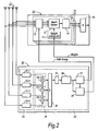
- Fig. 2 is a diagram illustrating an embodiment of an array antenna receiver structure of the present invention.
- a radio frequency signal received by each antenna element of the array antenna 21 is converted to a baseband signal in a frequency converting unit and is then converted to the digital baseband signal through discretion and quantization in an A/D converting unit (not illustrated).
- the digital baseband signal is then inputted to an adaptive array receiving unit 10 for conducting beam forming and demodulation process and the searcher 20 for path-searching.
- the signals of a plurality of antenna elements of the array antenna 21 are inputted.
- the signals of a plurality of antenna elements of the array antenna 21 are inputted to a correlation detecting unit 22 and is then inputted to an antenna-to-antenna correlation estimating unit 23 as the complex correlation signals through the correlation process (22-1 to 22-4) for the despreading process in each antenna.
- the complex correlation value of a certain antenna element is multiplied to the complex conjugate of the complex correlation value of the adjacent reference antenna element in the antenna-to-antenna (complex) correlation unit 24 in view of obtaining the correlation between the complex correlation signals from the antenna elements.
- the antenna-to-antenna correlation value can be obtained.
- a large signal in almost the equal level among the antenna elements at the time when the path exists can be obtained by adding (combining process) the correlation values among the antenna elements obtained in the combining unit 29. Namely, the signal element can be increased up to the value multiplied by the number of antenna elements.
- the noise namely small level signal is combined at random and the signals are averaged without multiplication with the number of antenna element. Distribution of noise for the combined signal is suppressed for that before the combining.
- the signal obtained by combining the antenna-to- antenna correlation values compensates for variation in the path-level such as the fading through temporal averaging in the averaging unit 25. Thereby, accuracy in the estimation of the antenna-to-antenna correlation can be improved.
- This antenna-to-antenna correlation value is expressed with a vector having constant value of amplitude and phase which does not depend on the modulation data.
- An output value of the averaging process in the averaging unit 25 can also be obtained as the antenna-to- antenna correlation value.
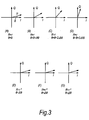
- Figs. 3A to 3G illustrates an antenna structure of the linear array antenna, in which four antenna elements are used (antenna 0 to antenna 3). Each vector has a respective length R and phase angle ⁇ .
- Figs. 3A to 3D illustrate the complex correlation values of antennae 0 to 3, respectively.
- the length of each vector is equal.
- the value of vector length r depends on the receiving signal level.
- phase ⁇ is generating a phase difference of ⁇ determined by the angle of arrival (i.e. ⁇ depends on the incoming phase angle).
- an antenna-to-antenna complex correlation value is obtained from the complex correlation signal of each antenna element.
- Figs. 3E to 3G illustrate the antenna-to-antenna complex correlation values of the antenna elements 0 and 1, antenna elements 1 and 2, and antenna elements 2 and 3 respectively.
- the antenna-to-antenna complex correlation values obtained by the complex correlation process have the equal vector.
- the amplitude indicates a signal power value and the phase indicates the arrival direction.
- the phase of the antenna-to -antenna complex correlation value signal and an output of the averaging unit 25 in Fig. 2 indicates the arrival direction, while the amplitude thereof, the signal power.
- This antenna-to-antenna complex correlation value signal is stored to a complex delay profile unit 26.
- the path detecting unit 27 detects the path-timing exceeding the path detection threshold value on the basis of the delay profiles stored in the complex correlation profile unit 26 and transmits the timing pulse synchronized with the time of path.
- the phase difference detecting unit 28 calculates a phase difference of the detected path, namely the angle of arrival on the basis of the phase information of the antenna-to-antenna complex correlation value stored in the complex correlation delay profile unit 26 and the detection information from the path detecting unit 27, thereafter converts the data to the weight information with the calculation or using a table, and then transmits the weight information as the weight for beam forming.
- the searcher 20 calculates the weight itself and then transmits the weight to the adaptive array receiving unit 10.
- the phase difference information is transmitted from the phase difference detecting unit 28 and it is then converted to the weight in the weight setting unit 11.
- Each finger 15 of the adaptive array receiving unit 10 executes despreading by conducting the correlation process of the receiving signal and the spread code in the despreading unit 12 on the basis of the path-timing signal (timing pulse) transmitted from the path detecting unit 27.
- the demodulation processes such as coherent detection in the coherent detection unit 14 and RAKE combining in the RAKE combining unit 16 are conducted with the beam forming signal in the beam former 13.
- the weight calculated from the phase difference information is steadily used in the searcher 20, but it is also possible that the weight calculated by the searcher 20 is set as the initial value and thereafter the weight is updated in the weight setting unit 11 using the known algorithm.
- the common weight setting unit 11 is provided for all fingers, but it is also possible that different weights are respectively provided for each finger corresponding to each path.
- the antenna-to-antenna complex correlation value in this embodiment does not depend on frequency variation of the receiving signal.
- the combining process in the combining unit 29 can be realized with the vector adding process and the noise canceling effect can be improved more than that in the electrical power value combining process.
- the pilot pattern canceling function which has been essential in the prior art is not longer required and the signal other than the known pilot patterns can also be used, further resulting in improvement in the noise canceling effect.
- Fig. 4 illustrates the path detection probability characteristic (calculation result) for the CNR (carrier to noise power ratio) in the embodiment of the present invention illustrated in Fig. 2 .
- the characteristics A, C correspond to the receiving system which is different from that of the present invention (combining the power value of the antenna elements), while the characteristics B, D correspond to the embodiment of the present invention.
- the number of antenna elements is set to 2
- spreading factor is set to 256
- the pilot symbol is set to 4 symbols.
- the gain based on the spread gain and coherent combining becomes 30 dB (correlation process output of the searcher 200 in Fig. 6 ).
- the spread gain and the gain based on the coherent combining are identical to that in the combining the power value of the antenna elements and the CNR at the input point of complex multiplier for obtaining the antenna-to- antenna correlation value becomes 0 dB as in the case of the structure in the combining the power value of antenna elements.
- the CNR generates deterioration of 3dB in the complex multiplier of the antenna-to-antenna correlation unit 24 of Fig. 2 .
- the probability of path detection for deterioration of the CNR in the present invention (B, D) is improved in comparison with that of the prior art (A, C).
- Fig. 5 illustrates another embodiment of the array antenna communication apparatus structure of the present invention.
- the signals received by the array antenna 21 are converted to the baseband signal in the frequency converter not illustrated and then converted again to the digital baseband signal through discretion and quantization in the A/D converting unit.
- the digital baseband signal is inputted to the searcher 20 for conducting the search of path.
- the searcher in this embodiment of the present invention obtains phase difference of the detected paths with the structure and process which are similar to that of Fig. 2 .
- the phase difference of the complex correlation value obtained indicates the angle of arrival and high speed transmitting beam forming may be realized by using such phase difference as the weight of transmitting beam by converting it to the weight.
- the beam of transmitting signal can be formed for the arrival direction of the receiving signal.
- the transmitting beam forming process is conducted in the transmitting beam former 31.
- the antenna-to-antenna correlation value of the path of the maximum correlation value detected by the searcher 20 is used.
- the adaptive array transmitting unit 30 including the transmitting beam former 31 comprises the spread processing unit 32 for spread process of the transmitting data, transmitting beam former 31, and weight setting unit 33.
- Detection of the arrival direction can also be utilized in a base station to provide the management information to an operator to detect the accommodation condition of users.
Landscapes
- Physics & Mathematics (AREA)
- Mathematical Physics (AREA)
- Engineering & Computer Science (AREA)
- Computer Networks & Wireless Communication (AREA)
- Signal Processing (AREA)
- Radio Transmission System (AREA)
- Variable-Direction Aerials And Aerial Arrays (AREA)
Description
- The present invention relates to radio communication apparatuses utilizing an array antenna and a method of detecting path-timing thereof and particularly to structures for processing the baseband signal.
- As the mobile communication system for the next generation, development of a digital cellular radio communication system utilizing the DS-CDMA (Direct Spread Code Division Multiple Access) technology is now under way.
- The CDMA system has been proposed to realize simultaneous communications by assigning channels using codes. In this system, the signals from the other channels under simultaneous communications generate interference and thereby the number of channels for simultaneous communications (capacity of channel) is restricted as a result.
- That is, in a mobile communication system utilizing the DS-CDMA technology, communication quality (average bit error rate during digital communication) is deteriorated by the amount of interference from the other users having multiple connections and the system capacity is determined based on the number of multiple access users satisfying the predetermined communication quality.
- Accordingly, adaptation of interference suppressing technology is effective for increasing the channel capacity.
- Adaptive array antenna is a technology which can be adaptively introduced for beam forming to the desired users and null point forming to the user who generates a large interference source and is also a technology to enable an increase in the channel capacity.
- Namely, radio signals can be received at higher sensitivity from the desired user by forming the signal beam in the direction of the desired user and directing the null point to the user who is a large interference source.
- The channel capacity can be increased by reducing amount of interference as described above.
- Moreover, in the CDMA communication system in a mobile communication environment, system capacity may be lowered due to the differences in the distances to the base station from many users who are communicating with only one base station.
- Therefore, system capacity can be increased by controlling the transmitting power to equalize the received power of each user of the base station.
- When the array antenna is adapted to the DS-CDMA system to execute transmit power control, the transmit power control is performed to make constant the SIR (signal to interference power ratio) after beam forming and RAKE combining.
-
Japanese patent publication no. JP200284216A -
European patent publication no. EP1231720A2 discloses an adaptive antenna receiving apparatus in which a path timing is detected on the basis of a delay profile generated from an output of each signal sequence by calculating power values. -
Fig. 6 illustrates a prior art structure of a baseband signal processing unit of the existing DS-CDMA array antenna receiving apparatus shown inJapanese Published Unexamined Patent Application No. 84216/2002 - The radio frequency signal received with each antenna element of the
array antenna 201, consisting of a plurality of antenna elements, is converted to the baseband signal in a frequency converting unit and is then converted, by an A/D converter to the discrete/quantized digital baseband signal (not illustrated). - The digital baseband signal is then input to an adaptive
array receiving unit 100 for executing the beam forming and demodulation process and asearcher 200 to execute the path-search. - The adaptive
array receiving unit 100 is formed of a plurality offingers 101 for receiving a multi-path signal with the RAKE receiving method and eachfinger 101 is provided, for the receiving signal process of each path, with a despreading unit (inverse diffusing unit) 102, a beam former 103 and a coherent (synchronized) detectingunit 104 to execute the receiving signal process of each path. - The RAKE reception is performed by coherently combining the output signals demodulated by the
fingers 101 in theRAKE combining unit 108. - Moreover, a
weight updating unit 106 using an adaptive algorithm is also included in the adaptive beam forming in accordance with the receiving environment. Since the weight updating algorithm of thisweight updating unit 106 is well-known, a detailed description is omitted here. - According to this weight updating algorithm, the amount of interference can be reduced by directing the beam to the desired direction and moreover directing the null point to the direction of other users having the larger interference power.
- The beam former 103 adjusts the relative phase of the received signal or transmitted signal and then changes the direction in which the transmit/receive intensity of the signal transmitted from the array antenna is most intensive (direction of beam forming) by multiplying a weight expressed with a complex number to the signal from each antenna element.
- The
weight updating unit 106 updates a value of weight used by the beam former 103 and then gives this updated value to the beam former 103 in order to optimize the direction of beam formed by the beam former 103. - Meanwhile, the signals of the
array antenna 201 input to thesearcher 200 are converted to complex correlation value signals through a correlation process (212-1 to 212-4) for despreading process for every antenna element with the correlation processing units 212-1, 212-2, 212-3, 212-4 and are then input to an antenna combining path-timing detecting unit 202 and an antenna-to-antennacorrelation estimating unit 203. - In the antenna combining path-
timing detecting unit 202, the complex correlation value signals present after the correlation process of each antenna are converted to the value of powers by apower value converter 205 and are then combined with acombiner 206. - Accordingly, large signals of almost the same level can be obtained among the antenna elements at the time when the path exists, but when the path does not exist, and noise is appearing, random signals of lower levels are combined. As a result, the signal element is multiplied with the number of antennas, but noise is not multiplied with the number of antennas and is equalized to an average value. Therefore, the distribution of noise for the signal after combining is suppressed in comparison with that before combining.
- The signal obtained by combining the complex correlation values for every antenna element is performed to a temporal average by accumulating the values of powers at the predetermined time in an
averaging unit 207 and delay profiles are stored into adelay profile unit 208 after the averaging process of variations resulting from fading in each path. - The path-timing detection is executed by searching the path in the larger level in the
path detecting unit 209 using the delay profile. - In the antenna-to-antenna
correlation estimating unit 203, the antenna-to-antenna correlation value (the cross-correlation value between the received signals by adjacent antenna elements) is estimated in the antenna-to-antenna correlation unit 210 and the estimated antenna-to-antenna correlation value is performed to a temporal average in theaveraging unit 211. Thereby, variation in the level of the path due to fading can be compensated. - As the output of the averaging process by the averaging
unit 211, an antenna-to-antenna correlation estimating value corresponding to each timing of the delay profile can be obtained. - In the adaptive
array receiving unit 100, the phase term information of the antenna-to-antenna correlation estimating value obtained from thesearcher 200 is converted to weight information in a weight converting unit (weight setting unit) 105 and is set as an initial value of theweight updating unit 106. - A plurality of path-timing information pieces detected by the
searcher 200 are sent to afinger assigning unit 107 of the adaptivearray receiving unit 100 and is used as the despreading timing of eachfinger 101. - In the
Fig. 6 system, the path-timing detection is performed with a correlation process for each antenna element in the searcher, conversion of the obtained complex correlation values to the powers, and then combining (adding) of these powers. - The reason is that since the complex correlation value of each antenna element generates phase rotation due to variation in frequency (Doppler, carrier frequency variation or the like) of the receiving signal, when the complex correlation values of antenna elements are all added in voltage, namely added as vectors, the values after the combining process may be deteriorated in accordance with the complex correlation values to be added and therefore the complex correlation values of antenna elements cannot be added as vectors.
- Accordingly, the complex correlation values must be converted to powers in view of eliminating influence by phase rotation.
- As described above, frequency variation must be taken into consideration in the
Fig. 6 system and the averaging process is executed after conversion to power values in the length of a temporal average where frequency variation cannot be neglected. - Moreover, in the
Fig. 6 system, the delay profile is obtained by conducting the temporal averaging process after the correlation process (corresponding to the despreading process) is executed, using a replica of the spread code and the receive signal in the searcher. However, the receive signal vector is rotated by the modulation data. - Therefore, the polarity of symbols must be cancelled in the case where the temporal average process is executed for a plurality of symbols and only the known pilot symbol part can usually be used and only a small number of samples may be used.
- Therefore, a need arises for a technique that can realize stable operation of the system and improve system capacity through improvement in the path detection characteristics and that can improve the noise cancellation effect.
- It is desirable to realize stable system operation and improve system capacity through improvement in the path detection characteristics when the array antenna is adapted by providing a circuit configuration of the searcher to realize high speed beam forming in the baseband processing unit comprised in the receiving apparatus utilizing the array antenna.
- Moreover, it is also desirable is to improve the noise cancellation effect by providing a circuit configuration to be capable of neglecting phase rotation of the receiving signal due to frequency variation and modulation data by canceling the phase rotation.
- An array antenna radio communication apparatus of one embodiment of the present invention comprises a searcher means for receiving signals from a part or the entire part of the array antenna having of a plurality of antenna elements and for detecting the path-timing of the received signals and a signal processing means to execute despreading of signals received from the antenna elements on the basis of the path-timing obtained from the searcher means, wherein the searcher means also comprises a correlation means for obtaining first correlation values as the correlation values in the received signals, an antenna-to-antenna correlation means for obtaining second correlation values as the correlation values of the first correlation values, and a path-timing detecting means for detecting the path-timing on the basis of an amplitude information obtained from the second correlation values.
- Such searcher means of the array antenna radio communication apparatus described above may comprise an antenna-to-antenna correlation processing means for obtaining the phase difference information and the amplitude information among antenna elements on the basis of the second correlation values obtained through combining of the correlation values between the first correlation values, and a phase difference detecting means for giving a weight to a beam former means to form the signal beam of the array antenna on the basis of the phase difference information.
- Moreover, the array antenna radio communication apparatus described above may introduce the structure of comprising a transmitting beam forming means to form the transmitting beam on the basis of the second correlation values obtained with the antenna-to-antenna correlation means.
- According to an embodiment of the present invention, the arrival direction of radio waves from users can be estimated and the power value of signals can also be detected by obtaining a correlation value of the signals from each antenna element of the array antenna and then obtaining correlation value between the antennas. Therefore, scale of circuit can be reduced because calculation of power value and process for averaging with the other circuits are no longer required unlike the prior art.
- In addition, since the phase of the antenna-to-antenna complex correlation value does not depend on the carrier frequency variation of the receiving signal and the modulation signal, but only on the arrival direction of signals, the averaging process can be realized by addition of vectors of the antenna-to-antenna correlation values (the cross-correlation value between the received signals by adjacent antenna elements) and thereby deterioration of path detecting accuracy can be prevented.
- Moreover, since the searcher detects the path and estimates the arrival direction using an antenna-to- antenna complex correlation value delay profile obtained with addition of vectors, it can perform the stable path searcher operation of the system to which the array antenna is adapted.
- Moreover, since vector rotation due to frequency variation is not generated by taking an antenna-to-antenna correlation value and the phase of vectors is constant not depending on the modulation data, not only the known pilot symbol part but also unknown modulation data part can be utilized, the number of samples for the averaging process can be increased, the noise cancellation effect can also be improved, and quality of the receiving signal and transmitting signal may be kept in the higher quality.
- Moreover, since the phase of vectors is kept constant, the pilot pattern canceling process (the pilot bit mask process) is not required even for obtaining the temporal average of a plurality of symbols using the known pilot patterns and the noise canceling effect can further be enhanced.
- Owing to the effects described above, increase in the transmitting power generated by deterioration of path searching characteristics and incomplete beam forming can be suppressed when the array antenna is adapted to the CDMA mobile communication system.
- Accordingly, the system capacity can be increased without deterioration of characteristics when the array antenna is adapted in the CDMA system in which the system capacity is restricted by amount of interference from the other users.
- Reference will now be made, by way of example, to the accompanying drawings, in which:
-
Fig. 1 is a diagram for describing the principle of a preferred embodiment of the present invention. -
Fig. 2 is a diagram illustrating an embodiment of an array antenna receiver structure of the present invention. -
Figs. 3A to 3G illustrates an antenna structure of the linear array antenna, in which four antenna elements are used. -
Fig. 4 illustrates the path detection probability characteristic (calculation result) for the CNR (carrier to noise power ratio) in the embodiment of the present invention illustrated inFig. 2 . -
Fig. 5 illustrates another embodiment of the array antenna communication apparatus structure of the present invention. -
Fig. 6 illustrates a prior art structure of a baseband signal processing unit of the existing DS-CDMA array antenna receiving apparatus shown inJapanese Published Unexamined Patent Application No. 84216/2002 -
Fig. 1 is a diagram for describing the principle of a preferred embodiment of the present invention. - All signals of the
array antenna 21 consisting of a plurality of antenna elements are inputted to asearcher 20. After the correlation process for despreading is conducted for each antenna element in thecorrelation detecting unit 22 of thesearcher 20, the signals are inputted to an antenna-to-antennacorrelation estimating unit 23. - In the antenna-to-antenna correlation estimating unit (antenna-to-antenna correlation processing unit) 23, the antenna-to-antenna correlation value is estimated using the signal obtained by combining (adding) the complex correlation value signals after the correlation processes of antennas in order to perform the path-timing detection and phase difference extraction (calculation of weight information using phase difference).
- The interface between an adaptive
array receiving unit 10 and thesearcher 20 is provided with a path- timing signal and a weight signal. - The adaptive
array receiving unit 10 is formed of a plurality offingers 15 for the RAKE reception of the multi-path signal. Eachfinger 15 comprises a despreading unit (inverse diffusing unit) 12, a beam former 13, and a coherent detectingunit 14 and performs the receiving signal process of each path. - The RAKE reception can be realized through the coherent combining of the output signals demodulated with each
finger 15 in theRAKE combining unit 16. - Moreover, the weight information obtained from the
searcher 20 is set (sent) to aweight setting unit 11. -
Fig. 2 is a diagram illustrating an embodiment of an array antenna receiver structure of the present invention. - A radio frequency signal received by each antenna element of the
array antenna 21 is converted to a baseband signal in a frequency converting unit and is then converted to the digital baseband signal through discretion and quantization in an A/D converting unit (not illustrated). - The digital baseband signal is then inputted to an adaptive
array receiving unit 10 for conducting beam forming and demodulation process and thesearcher 20 for path-searching. - In the
searcher 20, the signals of a plurality of antenna elements of thearray antenna 21 are inputted. - The signals of a plurality of antenna elements of the
array antenna 21 are inputted to acorrelation detecting unit 22 and is then inputted to an antenna-to-antennacorrelation estimating unit 23 as the complex correlation signals through the correlation process (22-1 to 22-4) for the despreading process in each antenna. - In the antenna-to-antenna
correlation estimating unit 23, the complex correlation value of a certain antenna element is multiplied to the complex conjugate of the complex correlation value of the adjacent reference antenna element in the antenna-to-antenna (complex)correlation unit 24 in view of obtaining the correlation between the complex correlation signals from the antenna elements. As a result, the antenna-to-antenna correlation value can be obtained. - A large signal in almost the equal level among the antenna elements at the time when the path exists can be obtained by adding (combining process) the correlation values among the antenna elements obtained in the combining
unit 29. Namely, the signal element can be increased up to the value multiplied by the number of antenna elements. - Meanwhile, when the path does not exist, the noise, namely small level signal is combined at random and the signals are averaged without multiplication with the number of antenna element. Distribution of noise for the combined signal is suppressed for that before the combining.
- The signal obtained by combining the antenna-to- antenna correlation values compensates for variation in the path-level such as the fading through temporal averaging in the averaging
unit 25. Thereby, accuracy in the estimation of the antenna-to-antenna correlation can be improved. - This antenna-to-antenna correlation value is expressed with a vector having constant value of amplitude and phase which does not depend on the modulation data.
- An output value of the averaging process in the averaging
unit 25 can also be obtained as the antenna-to- antenna correlation value. - Here, the antenna-to-antenna correlation of the present invention will be described with reference to
Fig. 3A to 3G . -
Figs. 3A to 3G illustrates an antenna structure of the linear array antenna, in which four antenna elements are used (antenna 0 to antenna 3). Each vector has a respective length R and phase angle θ. -
Figs. 3A to 3D illustrate the complex correlation values ofantennae 0 to 3, respectively. The complex correlation signal of each antenna element, obtained by the correlation process ofFig. 2 , has the amplitude R which is equal to the length of vector r (R = r) as illustrated inFigs. 3A to 3D . The length of each vector is equal. The value of vector length r depends on the receiving signal level. - Moreover, the phase θ is generating a phase difference of Δθ determined by the angle of arrival (i.e. Δθ depends on the incoming phase angle).
- Next, an antenna-to-antenna complex correlation value is obtained from the complex correlation signal of each antenna element.
-
Figs. 3E to 3G illustrate the antenna-to-antenna complex correlation values of theantenna elements antenna elements antenna elements - Accordingly, the antenna-to-antenna complex correlation values obtained by the complex correlation process have the equal vector. The amplitude indicates a signal power value and the phase indicates the arrival direction.
- With the calculation described above, all complex correlation values have the equal vector in the structure of the linear array antenna. Therefore, the noise element is averaged by combining the vectors and the antenna-to-antenna complex correlation values are added. Thereby, the noise cancellation effect can be attained.
- As described above, the phase of the antenna-to -antenna complex correlation value signal and an output of the averaging
unit 25 inFig. 2 indicates the arrival direction, while the amplitude thereof, the signal power. - This antenna-to-antenna complex correlation value signal is stored to a complex
delay profile unit 26. - The
path detecting unit 27 detects the path-timing exceeding the path detection threshold value on the basis of the delay profiles stored in the complexcorrelation profile unit 26 and transmits the timing pulse synchronized with the time of path. - Meanwhile, the phase
difference detecting unit 28 calculates a phase difference of the detected path, namely the angle of arrival on the basis of the phase information of the antenna-to-antenna complex correlation value stored in the complex correlationdelay profile unit 26 and the detection information from thepath detecting unit 27, thereafter converts the data to the weight information with the calculation or using a table, and then transmits the weight information as the weight for beam forming. - Here, the
searcher 20 calculates the weight itself and then transmits the weight to the adaptivearray receiving unit 10. However, it is also possible that the phase difference information is transmitted from the phasedifference detecting unit 28 and it is then converted to the weight in theweight setting unit 11. - Each
finger 15 of the adaptivearray receiving unit 10 executes despreading by conducting the correlation process of the receiving signal and the spread code in thedespreading unit 12 on the basis of the path-timing signal (timing pulse) transmitted from thepath detecting unit 27. - Using the weight from the phase
difference detecting unit 28 corresponding to the path-timing signal transmitted from thepath detecting unit 27, the demodulation processes, such as coherent detection in thecoherent detection unit 14 and RAKE combining in theRAKE combining unit 16 are conducted with the beam forming signal in the beam former 13. - In this embodiment, the weight calculated from the phase difference information is steadily used in the
searcher 20, but it is also possible that the weight calculated by thesearcher 20 is set as the initial value and thereafter the weight is updated in theweight setting unit 11 using the known algorithm. - Moreover, in this embodiment, the common
weight setting unit 11 is provided for all fingers, but it is also possible that different weights are respectively provided for each finger corresponding to each path. - The antenna-to-antenna complex correlation value in this embodiment does not depend on frequency variation of the receiving signal.
- Accordingly, it is not required to convert the antenna-to-antenna complex correlation value to an electrical power value and the combining process in the combining
unit 29 can be realized with the vector adding process and the noise canceling effect can be improved more than that in the electrical power value combining process. - Moreover, since the antenna-to-antenna complex correlation value does not depend on the modulation data, the pilot pattern canceling function which has been essential in the prior art is not longer required and the signal other than the known pilot patterns can also be used, further resulting in improvement in the noise canceling effect.
-
Fig. 4 illustrates the path detection probability characteristic (calculation result) for the CNR (carrier to noise power ratio) in the embodiment of the present invention illustrated inFig. 2 . - The characteristics A, C correspond to the receiving system which is different from that of the present invention (combining the power value of the antenna elements), while the characteristics B, D correspond to the embodiment of the present invention.
- As the calculation parameters in the case of combining the power value of the antenna elements, the number of antenna elements is set to 2, spreading factor is set to 256 and the pilot symbol is set to 4 symbols. In this case, the gain based on the spread gain and coherent combining becomes 30 dB (correlation process output of the
searcher 200 inFig. 6 ). When the CNR of the receiving signal is assumed as -30dB, the CNR = 0dB can be obtained at the power conversion point. - Moreover, when the multiplication of the integral length and the number of antenna elements is defined as N, Chi-Square Distribution of the degrees of freedom n = 2 (I.Q) × N (integral length).
- On the other hand, in the present embodiment of the present invention, the spread gain and the gain based on the coherent combining (output of
correlation detecting unit 22 inFig. 2 ) are identical to that in the combining the power value of the antenna elements and the CNR at the input point of complex multiplier for obtaining the antenna-to- antenna correlation value becomes 0 dB as in the case of the structure in the combining the power value of antenna elements. - The CNR generates deterioration of 3dB in the complex multiplier of the antenna-to-
antenna correlation unit 24 ofFig. 2 . - Next, the integral process is executed in the averaging
unit 25. When the integral length is defined as N, an improvement coefficient of the CNR is expressed with √N and the square of the vector length (square of the amplitude) is obtained thereafter. However, distribution of this correlation energy is indicated by Chi-Square Distribution of the degrees of freedom n = 2. - The characteristics A, B corresponds to N = 128, while the characteristics C, D, to N = 256. Therefore, it is the effect of the present invention to make clear the probability of path detection for deterioration of the CNR.
- As indicated by the characteristics A, B or characteristics C, D, the probability of path detection for deterioration of the CNR in the present invention (B, D) is improved in comparison with that of the prior art (A, C).
- Moreover, it can also be understood that when the integral length is doubled as indicated by the characteristics A, C, improvement in the path detection probability is about 2 dB. Moreover, when the integral length is doubled in the characteristics B, D in the embodiment of the present invention, improvement in the path detection probability is 3 dB.
- Namely, it can be understood that the characteristics are improved to a large extent for the combining the power value of the antenna elements in the prior art because the path detection probability can be considerably improved in embodiments of the present invention.
-
Fig. 5 illustrates another embodiment of the array antenna communication apparatus structure of the present invention. - The signals received by the
array antenna 21 are converted to the baseband signal in the frequency converter not illustrated and then converted again to the digital baseband signal through discretion and quantization in the A/D converting unit. - The digital baseband signal is inputted to the
searcher 20 for conducting the search of path. - The searcher in this embodiment of the present invention obtains phase difference of the detected paths with the structure and process which are similar to that of
Fig. 2 . - The phase difference of the complex correlation value obtained indicates the angle of arrival and high speed transmitting beam forming may be realized by using such phase difference as the weight of transmitting beam by converting it to the weight.
- For transmission of the transmitting signal, since a terminal clearly exists in the arrival direction of the receiving signal, the beam of transmitting signal can be formed for the arrival direction of the receiving signal.
- The transmitting beam forming process is conducted in the transmitting beam former 31.
- In this case, since only one transmitting beam is usually formed, the antenna-to-antenna correlation value of the path of the maximum correlation value detected by the
searcher 20 is used. - The adaptive
array transmitting unit 30 including the transmitting beam former 31 comprises thespread processing unit 32 for spread process of the transmitting data, transmitting beam former 31, andweight setting unit 33. - Detection of the arrival direction can also be utilized in a base station to provide the management information to an operator to detect the accommodation condition of users.
- Although specific embodiments of the present invention have been described, it will be understood by those of skill in the art that there are other embodiments that are equivalent to the described embodiments. Accordingly, it is to be understood that the invention is not to be limited by the specific illustrated embodiments, but only by the scope of the appended claims.
Claims (10)
- An array antenna radio communication apparatus having
a searcher unit (20) operable to receive signals from at least a portion of an array antenna (21) having a plurality of antenna elements and operable to detect a path-timing of the received signals, the searcher unit (20) comprising:a correlation unit (22) operable to obtain first correlation values as correlation values of the received signals for each antenna element;an antenna-to-antenna correlation processing unit (23) operable to obtain second correlation values as correlation values of the first correlation values, and to obtain phase difference information and amplitude information among the antenna elements based on the second correlation values;a path-timing detecting unit (27) operable to detect path-timing based on amplitude information obtained from the second correlation values; anda phase difference detecting unit (28) operable to give a weight to a beam former (13) to form a signal beam of the array antenna (21) on the basis of phase difference information;wherein the array antenna radio communication apparatus also has a signal processing unit (10) operable to execute despreading of signals received from the antenna elements based on the path-timing obtained from the searcher unit (20). - The array antenna radio communication apparatus according to claim 1, wherein the phase difference detecting unit (28) further comprises a weight setting unit operable to update the weight on a real-time basis.
- The array antenna radio communication apparatus according to claim 2, wherein the antenna-to-antenna correlation processing unit (23) is further operable to convert the phase difference information obtained based on the second correlation value to a weight and to transmit the converted weight to the weight setting unit.
- The array antenna radio communication apparatus according to claim 2, wherein the antenna-to-antenna correlation processing unit (23) is further operable to transmit the phase difference information obtained based on the second correlation value to the weight setting unit and the weight setting unit is operable to convert the phase difference information to a weight.
- The array antenna radio communication apparatus according to any preceding claim, wherein the signal processing unit (10) further comprises a plurality of fingers (15), each of which is provided with a beam former (13) and a weight setting unit.
- The array antenna radio communication apparatus according to claim 5, wherein the antenna-to-antenna correlation processing unit (23) is further operable to obtain a second correlation value for each path and to independently provide a weight for beam formation to each finger (15) using the second correlation value corresponding to each path.
- The array antenna radio communication apparatus according to claim 5 or 6, wherein the antenna-to-antenna correlation processing unit (23) is further operable to obtain an average value for a time of the second correlation value combined among the antenna elements.
- The array antenna radio communication apparatus according to any preceding claim, wherein the signal processing unit (10) further comprises a plurality of fingers (15), each of which is provided with a weight setting unit, and the signal processing unit (10) is further operable to obtain the second correlation value obtained by the antenna- to-antenna correlation processing unit (23) and to provide a weight for the formation of an identical beam to fingers of a same channel.
- The array antenna radio communication apparatus according to any preceding claim, further comprising a transmitting beam forming unit operable to form the transmitting beam based on the second correlation values obtained with the antenna-to-antenna correlation processing unit (23).
- A path-timing detecting method in an array antenna radio communication apparatus for receiving signals from at least a portion of an array antenna (21) having a plurality of antenna elements, comprising the steps of:obtaining first correlation values as correlation values of the received signals each antenna element;obtaining second correlation values as antenna-to-antenna correlation values of the first correlation values;obtaining phase difference information and amplitude information among the antenna elements based on the second correlation values; anddetecting path-timing based on amplitude information obtained from the second correlation values.
Applications Claiming Priority (2)
| Application Number | Priority Date | Filing Date | Title |
|---|---|---|---|
| JP2004099299A JP4329594B2 (en) | 2004-03-30 | 2004-03-30 | Array antenna radio communication apparatus and path timing detection method thereof |
| JP2004099299 | 2004-03-30 |
Publications (2)
| Publication Number | Publication Date |
|---|---|
| EP1583258A1 EP1583258A1 (en) | 2005-10-05 |
| EP1583258B1 true EP1583258B1 (en) | 2011-04-20 |
Family
ID=34879974
Family Applications (1)
| Application Number | Title | Priority Date | Filing Date |
|---|---|---|---|
| EP20040255514 Expired - Lifetime EP1583258B1 (en) | 2004-03-30 | 2004-09-13 | Array antenna radio communication apparatuses |
Country Status (5)
| Country | Link |
|---|---|
| US (1) | US6985106B2 (en) |
| EP (1) | EP1583258B1 (en) |
| JP (1) | JP4329594B2 (en) |
| CN (1) | CN1677894A (en) |
| DE (1) | DE602004032306D1 (en) |
Families Citing this family (8)
| Publication number | Priority date | Publication date | Assignee | Title |
|---|---|---|---|---|
| JP4524147B2 (en) * | 2004-06-30 | 2010-08-11 | 京セラ株式会社 | COMMUNICATION DEVICE, CALIBRATION METHOD, AND PROGRAM |
| US8095185B2 (en) * | 2006-06-09 | 2012-01-10 | Telefonaktiebolaget L M Ericsson (Publ) | Estimation of angular parameters of a signal at an antenna array |
| JP5186748B2 (en) * | 2006-09-29 | 2013-04-24 | 富士通株式会社 | Wireless communication apparatus and wireless communication method |
| US8396151B2 (en) * | 2006-10-19 | 2013-03-12 | Qualcomm Incorporated | Timing tracking in a multiple receive antenna system |
| JP5344978B2 (en) | 2009-04-22 | 2013-11-20 | パナソニック株式会社 | Directional pattern determination method |
| US20100304744A1 (en) * | 2009-05-29 | 2010-12-02 | Qualcomm Incorporated | Method and apparatus for performing searches with multiple receive diversity (rxd) search modes |
| US9584231B2 (en) * | 2014-10-30 | 2017-02-28 | Samsung Electronics Co., Ltd. | Integrated two dimensional active antenna array communication system |
| EP4200988A1 (en) * | 2020-08-20 | 2023-06-28 | Telefonaktiebolaget LM Ericsson (publ) | Coherent summing of signals from distributed radio access points |
Family Cites Families (9)
| Publication number | Priority date | Publication date | Assignee | Title |
|---|---|---|---|---|
| US6683924B1 (en) * | 1999-10-19 | 2004-01-27 | Ericsson Inc. | Apparatus and methods for selective correlation timing in rake receivers |
| WO2001067627A1 (en) * | 2000-03-06 | 2001-09-13 | Fujitsu Limited | Cdma receiver and searcher of the cdma receiver |
| JP4087549B2 (en) | 2000-09-06 | 2008-05-21 | 富士通株式会社 | Array antenna wireless communication device |
| JP2002237766A (en) | 2001-02-08 | 2002-08-23 | Nec Corp | Adaptive antenna receiving device |
| JP3558053B2 (en) | 2001-06-06 | 2004-08-25 | 日本電気株式会社 | Adaptive antenna receiver |
| JP2003008483A (en) * | 2001-06-18 | 2003-01-10 | Nec Corp | Adaptive array antenna receiver |
| JP4086574B2 (en) * | 2002-04-12 | 2008-05-14 | 松下電器産業株式会社 | Path search circuit, radio reception device, and radio transmission device |
| JP3895228B2 (en) * | 2002-05-07 | 2007-03-22 | 松下電器産業株式会社 | Wireless communication apparatus and direction of arrival estimation method |
| JP3856126B2 (en) * | 2002-05-21 | 2006-12-13 | 日本電気株式会社 | Path timing detection method, path timing detection apparatus, and adaptive array antenna system |
-
2004
- 2004-03-30 JP JP2004099299A patent/JP4329594B2/en not_active Expired - Fee Related
- 2004-08-19 US US10/921,201 patent/US6985106B2/en not_active Expired - Fee Related
- 2004-09-13 DE DE200460032306 patent/DE602004032306D1/en not_active Expired - Lifetime
- 2004-09-13 EP EP20040255514 patent/EP1583258B1/en not_active Expired - Lifetime
-
2005
- 2005-03-10 CN CNA200510053707XA patent/CN1677894A/en active Pending
Also Published As
| Publication number | Publication date |
|---|---|
| JP2005286784A (en) | 2005-10-13 |
| US6985106B2 (en) | 2006-01-10 |
| JP4329594B2 (en) | 2009-09-09 |
| US20050219122A1 (en) | 2005-10-06 |
| EP1583258A1 (en) | 2005-10-05 |
| DE602004032306D1 (en) | 2011-06-01 |
| CN1677894A (en) | 2005-10-05 |
Similar Documents
| Publication | Publication Date | Title |
|---|---|---|
| US6385181B1 (en) | Array antenna system of wireless base station | |
| US7031368B1 (en) | Adaptive transmitter/receiver | |
| KR0164250B1 (en) | Receiver and repeater for spread spectrum communicaton | |
| KR100450694B1 (en) | Adaptive antenna reception apparatus | |
| US6657590B2 (en) | Adaptive antenna reception apparatus using reception signals by arrays antennas | |
| KR100445490B1 (en) | Radio base station device and radio communication method | |
| US7047044B2 (en) | Radio receiving device and radio receiving method | |
| KR100451278B1 (en) | Adaptive antenna receiving apparatus | |
| EP0948145A2 (en) | Radio communication apparatus and method with adaptive antenna array reception | |
| WO1997020400A1 (en) | Diversity receiver and control method therefor | |
| US20070189362A1 (en) | Method and system for channel estimation, related receiver and computer program product | |
| US7142888B2 (en) | Radio communication method, base station and mobile station | |
| EP0936755B1 (en) | Adaptive receiving device with antenna array | |
| US7565172B2 (en) | Adaptive antenna reception method and device | |
| US7505509B2 (en) | Receiving communication apparatus using array antenna | |
| JP4087549B2 (en) | Array antenna wireless communication device | |
| EP1583258B1 (en) | Array antenna radio communication apparatuses | |
| US6317611B1 (en) | Communication device with adaptive antenna | |
| KR100679435B1 (en) | Adaptive antenna receiver with excellent reception quality of directional beam from the early stage | |
| EP0924875B1 (en) | Diversity reception method and apparatus in a CDMA system | |
| US7593381B2 (en) | Mobile communication terminal, and antenna array directivity-pattern-controlling method | |
| JP2002026788A (en) | Receiver | |
| KR20040046498A (en) | A device and a operating method thereof improved beamforming for smart antenna in base site | |
| KR20040046499A (en) | A method of improved beam forming for smart antenna in base station |
Legal Events
| Date | Code | Title | Description |
|---|---|---|---|
| PUAI | Public reference made under article 153(3) epc to a published international application that has entered the european phase |
Free format text: ORIGINAL CODE: 0009012 |
|
| AK | Designated contracting states |
Kind code of ref document: A1 Designated state(s): AT BE BG CH CY CZ DE DK EE ES FI FR GB GR HU IE IT LI LU MC NL PL PT RO SE SI SK TR |
|
| AX | Request for extension of the european patent |
Extension state: AL HR LT LV MK |
|
| 17P | Request for examination filed |
Effective date: 20051031 |
|
| AKX | Designation fees paid |
Designated state(s): DE FR GB |
|
| 17Q | First examination report despatched |
Effective date: 20090701 |
|
| GRAP | Despatch of communication of intention to grant a patent |
Free format text: ORIGINAL CODE: EPIDOSNIGR1 |
|
| GRAS | Grant fee paid |
Free format text: ORIGINAL CODE: EPIDOSNIGR3 |
|
| GRAA | (expected) grant |
Free format text: ORIGINAL CODE: 0009210 |
|
| AK | Designated contracting states |
Kind code of ref document: B1 Designated state(s): DE FR GB |
|
| REG | Reference to a national code |
Ref country code: GB Ref legal event code: FG4D |
|
| REF | Corresponds to: |
Ref document number: 602004032306 Country of ref document: DE Date of ref document: 20110601 Kind code of ref document: P |
|
| REG | Reference to a national code |
Ref country code: DE Ref legal event code: R096 Ref document number: 602004032306 Country of ref document: DE Effective date: 20110601 |
|
| PGFP | Annual fee paid to national office [announced via postgrant information from national office to epo] |
Ref country code: GB Payment date: 20110923 Year of fee payment: 8 Ref country code: FR Payment date: 20110817 Year of fee payment: 8 |
|
| PLBE | No opposition filed within time limit |
Free format text: ORIGINAL CODE: 0009261 |
|
| STAA | Information on the status of an ep patent application or granted ep patent |
Free format text: STATUS: NO OPPOSITION FILED WITHIN TIME LIMIT |
|
| 26N | No opposition filed |
Effective date: 20120123 |
|
| REG | Reference to a national code |
Ref country code: DE Ref legal event code: R097 Ref document number: 602004032306 Country of ref document: DE Effective date: 20120123 |
|
| GBPC | Gb: european patent ceased through non-payment of renewal fee |
Effective date: 20120913 |
|
| REG | Reference to a national code |
Ref country code: FR Ref legal event code: ST Effective date: 20130531 |
|
| PG25 | Lapsed in a contracting state [announced via postgrant information from national office to epo] |
Ref country code: GB Free format text: LAPSE BECAUSE OF NON-PAYMENT OF DUE FEES Effective date: 20120913 Ref country code: DE Free format text: LAPSE BECAUSE OF NON-PAYMENT OF DUE FEES Effective date: 20130403 |
|
| PG25 | Lapsed in a contracting state [announced via postgrant information from national office to epo] |
Ref country code: FR Free format text: LAPSE BECAUSE OF NON-PAYMENT OF DUE FEES Effective date: 20121001 |
|
| REG | Reference to a national code |
Ref country code: DE Ref legal event code: R119 Ref document number: 602004032306 Country of ref document: DE Effective date: 20130403 |