EP1583199A2 - Desktop holder and portable terminal system - Google Patents
Desktop holder and portable terminal system Download PDFInfo
- Publication number
- EP1583199A2 EP1583199A2 EP05101796A EP05101796A EP1583199A2 EP 1583199 A2 EP1583199 A2 EP 1583199A2 EP 05101796 A EP05101796 A EP 05101796A EP 05101796 A EP05101796 A EP 05101796A EP 1583199 A2 EP1583199 A2 EP 1583199A2
- Authority
- EP
- European Patent Office
- Prior art keywords
- terminal
- connector
- storage medium
- external storage
- portable terminal
- Prior art date
- Legal status (The legal status is an assumption and is not a legal conclusion. Google has not performed a legal analysis and makes no representation as to the accuracy of the status listed.)
- Withdrawn
Links
Images


Classifications
-
- H—ELECTRICITY
- H02—GENERATION; CONVERSION OR DISTRIBUTION OF ELECTRIC POWER
- H02J—ELECTRIC POWER NETWORKS; CIRCUIT ARRANGEMENTS OR SYSTEMS FOR SUPPLYING OR DISTRIBUTING ELECTRIC POWER; SYSTEMS FOR STORING ELECTRIC ENERGY
- H02J7/00—Circuit arrangements for charging or discharging batteries or for supplying loads from batteries
- H02J7/70—Circuit arrangements for charging or discharging batteries or for supplying loads from batteries characterised by the mechanical construction
- H02J7/731—Circuit arrangements for charging or discharging batteries or for supplying loads from batteries characterised by the mechanical construction specially adapted for holding portable devices containing batteries
-
- H—ELECTRICITY
- H02—GENERATION; CONVERSION OR DISTRIBUTION OF ELECTRIC POWER
- H02J—ELECTRIC POWER NETWORKS; CIRCUIT ARRANGEMENTS OR SYSTEMS FOR SUPPLYING OR DISTRIBUTING ELECTRIC POWER; SYSTEMS FOR STORING ELECTRIC ENERGY
- H02J7/00—Circuit arrangements for charging or discharging batteries or for supplying loads from batteries
-
- H—ELECTRICITY
- H04—ELECTRIC COMMUNICATION TECHNIQUE
- H04M—TELEPHONIC COMMUNICATION
- H04M1/00—Substation equipment, e.g. for use by subscribers
- H04M1/72—Mobile telephones; Cordless telephones, i.e. devices for establishing wireless links to base stations without route selection
- H04M1/724—User interfaces specially adapted for cordless or mobile telephones
- H04M1/72403—User interfaces specially adapted for cordless or mobile telephones with means for local support of applications that increase the functionality
- H04M1/72409—User interfaces specially adapted for cordless or mobile telephones with means for local support of applications that increase the functionality by interfacing with external accessories
-
- H—ELECTRICITY
- H04—ELECTRIC COMMUNICATION TECHNIQUE
- H04M—TELEPHONIC COMMUNICATION
- H04M1/00—Substation equipment, e.g. for use by subscribers
- H04M1/26—Devices for calling a subscriber
- H04M1/27—Devices whereby a plurality of signals may be stored simultaneously
- H04M1/274—Devices whereby a plurality of signals may be stored simultaneously with provision for storing more than one subscriber number at a time, e.g. using toothed disc
- H04M1/2745—Devices whereby a plurality of signals may be stored simultaneously with provision for storing more than one subscriber number at a time, e.g. using toothed disc using static electronic memories, e.g. chips
- H04M1/2753—Devices whereby a plurality of signals may be stored simultaneously with provision for storing more than one subscriber number at a time, e.g. using toothed disc using static electronic memories, e.g. chips providing data content
- H04M1/2757—Devices whereby a plurality of signals may be stored simultaneously with provision for storing more than one subscriber number at a time, e.g. using toothed disc using static electronic memories, e.g. chips providing data content by data transmission, e.g. downloading
-
- H—ELECTRICITY
- H04—ELECTRIC COMMUNICATION TECHNIQUE
- H04M—TELEPHONIC COMMUNICATION
- H04M1/00—Substation equipment, e.g. for use by subscribers
- H04M1/72—Mobile telephones; Cordless telephones, i.e. devices for establishing wireless links to base stations without route selection
- H04M1/724—User interfaces specially adapted for cordless or mobile telephones
- H04M1/72403—User interfaces specially adapted for cordless or mobile telephones with means for local support of applications that increase the functionality
- H04M1/7243—User interfaces specially adapted for cordless or mobile telephones with means for local support of applications that increase the functionality with interactive means for internal management of messages
-
- H—ELECTRICITY
- H04—ELECTRIC COMMUNICATION TECHNIQUE
- H04M—TELEPHONIC COMMUNICATION
- H04M2250/00—Details of telephonic subscriber devices
- H04M2250/14—Details of telephonic subscriber devices including a card reading device
Definitions
- the present invention relates to a desktop holder of a portable terminal, and more particularly, to a desktop holder having a function of charging a battery pack built in the portable terminal and an external memory function.
- a portable terminal represented by a cellular phone has to be charged regularly in order to operate with a battery pack as its power source.
- a desktop holder for a portable terminal having a function of charging the battery pack is sold in sets with a portable terminal or sold separately.
- Portable terminal units require high value-added quality and high functionality to inevitably invite an increase in memory capacity.
- For increasing the memory capacity there are a method of increasing the capacity of an internal memory and a method of using an external memory.
- a memory card is a card-type storage device using a flash memory whose representative is an MMC (multi media card), an SD memory card, or a memory stick.
- Japanese Patent Laid-Open (Kokai) No. 2003-283610 discloses a battery charge adaptor having a function of charging a battery pack built in a cellular phone and an external memory function.
- the battery charge adaptor disclosed in Article 1 includes an adaptor having a plug to be inserted into a socket of a commercial power source and a light emitting element, a connector to be connected to an external connection terminal of the cellular phone, and a connecting means which electrically connects the adaptor and the connector.
- the adaptor includes an AC/DC converter which converts AC voltage from the commercial power source into DC voltage for charge and supplies the obtained voltage to the cellular phone through the connector and the connecting means to charge the battery pack, a charge monitoring means which monitors whether charge of the battery pack has been completed or not, a storage means as an external storage, and a control means which transfers storage data including at least data of a telephone book from an internal memory of the cellular phone to make the storage means store it upon detecting the completion of the charge by the charge monitoring means, and notifies the data transferring state by the light emitting element.
- the storage data including the telephone book data stored in the internal memory of the cellular phone can be automatically stored in the storage means built in the battery charge adaptor at the completion of battery charge of the battery pack of the cellular phone and conversely, the storage data held in the battery charge adaptor can be automatically transferred to the internal memory of the cellular phone.
- the storage means built in the battery charge adaptor is not detachable and cannot transfer data to other units than the cellular phone. Therefore, the data stored in the external memory cannot be used in a personal computer and other kinds of portable terminals, that is, the data cannot be shared.
- an object of the present invention is to provide a desktop holder and a portable terminal system which have a function of charging a battery pack and an external memory function and which enable a detachable memory card as an external memory to be used and access to the memory card to be controlled according to key operation of the portable terminal.
- a desktop holder which accommodates a portable terminal, comprises a connector which electrically connects an external storage medium inserted into an external storage medium slot and an external connection terminal of the accommodated portable terminal to enable read and write from/to the external storage medium by operation of the portable terminal, and a connector which supplies charging DC voltage supplied from an AC adaptor to the portable terminal to charge a battery.
- the desktop holder includes, as contained in a case, a first connector having a charge terminal to be connected to an output terminal of the AC adaptor which converts AC voltage of a commercial power source into charging DC voltage and outputs the obtained voltage, a second connector having an external storage medium terminal to be connected to the external storage medium, and a third connector having a charge terminal to be connected to the external connection terminal of the portable terminal and connected to the charge terminal of the first connector and a terminal connected to the external storage medium terminal of the second connector.
- the second connector is provided in the external storage medium slot provided in the case, and the third connector is provided in a portable terminal insertion inlet provided in the case.
- the desktop holder further comprises a regulator which receives input of the charging DC voltage from the charge terminal of the first connector and converts the voltage into operating voltage to output the obtained voltage, wherein the second connector includes a power source terminal to which output of the regulator is applied.
- the desktop holder is internally provided with a first connector having a charge terminal to be connected to an output terminal of an AC adaptor which converts AC voltage of a commercial power source into charging DC voltage and outputs the obtained voltage, a second connector having an external storage medium terminal to be connected to an external storage medium inserted into an external storage medium slot, and a third connector having a charge terminal to be connected to an external connection terminal of the portable terminal and connected to the charge terminal of the first connector and an external storage medium terminal connected to the external storage medium terminal of the second connector, and the portable terminal includes a fourth connector having a charge terminal and an external storage medium terminal to be electrically and physically connected to the third connector, a charging circuit which receives input of the charging DC voltage from the charge terminal of the fourth connector to charge a battery, and control means which controls read and write from/to the external storage medium inserted into the external storage medium slot of the desktop holder to be connected through the external storage medium terminal of the fourth connector.
- the second connector is provided in the external storage medium slot provided in the case of the desktop holder
- the third connector is provided in a portable terminal insertion inlet provided in the case of the desktop holder.
- the portable terminal system further comprises a regulator which receives input of the charging DC voltage from the charge terminal of the first connector and converts the voltage into operating voltage to output the obtained voltage, wherein the second connector includes a power source terminal to which output of the regulator is applied.
- control means of the portable terminal with either one of an internal memory of the portable terminal and the external storage medium inserted into the external storage medium slot set to be a transfer source memory and the other set to be a transfer destination memory, displays a list of folders of the transfer source memory on a display device of the portable terminal to select a transfer source folder by key operation and displays a list of folders of the transfer destination memory on the display device to make a user select a transfer destination folder by key operation, thereby reading data stored in the selected transfer source folder and writing the data into the selected transfer destination folder.
- the desktop holder is internally provided with a first connector having a charge terminal to be connected to an output terminal of an AC adaptor which converts AC voltage of a commercial power source into charging DC voltage and outputs the obtained voltage, a second connector having an external storage medium terminal to be connected to an external storage medium inserted into an external storage medium slot, a third connector having a charge terminal connected to the charge terminal of the first connector and an external interface terminal connected to the external storage medium terminal of the second connector, and control means having an interface conversion function of connecting the external storage medium terminal of the second connector and the external interface terminal, and the portable terminal includes a fourth connector having a charge terminal and an external interface terminal to be electrically and physically connected to the third connector, a charging circuit which receives input of the charging DC voltage from the charge terminal of the fourth connector to charge a battery, and control means which controls read and write from/to the external storage medium inserted into the external storage medium slot of the desktop holder to
- the second connector is provided in the external storage medium slot provided in the case of the desktop holder
- the third connector is provided in a portable terminal insertion inlet provided in the case of the desktop holder.
- the portable terminal system further comprises a regulator which receives input of the charging DC voltage from the charge terminal of the first connector and converts the voltage into operating voltage to output the obtained voltage, wherein the second connector includes a power source terminal to which output of the regulator is applied.
- the control means of the desktop holder includes a portable terminal side access controller, a card side access controller and a buffer memory, and wherein the portable terminal side access controller sends and receives data and a control signal to/from the control means of the portable terminal through the external interface terminal of the third connector by a procedure according to the external interface and at the time of write to the external storage medium, accumulates, in the buffer memory, data of an internal memory of the portable terminal received from the control means of the portable terminal, and at the time of read from the external storage medium, transfers the data of the external storage medium accumulated in the buffer memory to the control means of the portable terminal, and the card side access controller sends and receives data and a control signal to/from the external storage medium through the external storage medium terminal of the second connector by a procedure according to the external storage medium interface and at the time of write to the external storage medium, writes data of the internal memory accumulated in the buffer memory into the external storage medium and at the time of read from the external storage medium, accumulates, in the buffer memory, data read from the external
- control means of the portable terminal with either one of an internal memory of the portable terminal and the external storage medium inserted into the external storage medium slot set to be a transfer source memory and the other set to be a transfer destination memory, displays a list of folders of the transfer source memory on a display device of the portable terminal to select a transfer source folder by key operation and displays a list of folders of the transfer destination memory on the display device to make a user select a transfer destination folder by key operation, thereby reading data stored in the selected transfer source folder and writing the data into the selected transfer destination folder.
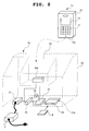
- a desktop holder 2 for a portable terminal 1 includes, within a case 20, a first connector 21 having a charge terminal 211 connected to an output terminal 301 of an AC adaptor 3 which converts AC voltage of a commercial power source into charging DC voltage of about 5V and outputs the obtained voltage, a regulator 22 which receives the charging DC voltage from the charge terminal 211 of the first connector 21 through a cable 101, converts it into operating voltage of about 3V and supplies the obtained voltage through a cable 102, a second connector 23 having a power source terminal 231 to which the output of the regulator 22 is applied through the cable 102 and an external storage medium terminal 232, and a third connector 24 having a charge terminal 241 which is connected to the charge terminal 211 of the first connector 21 through the cable 101, an external interface terminal 242 and an external storage medium terminal 243 which is connected to the external storage medium terminal 232 of the second connector 23 through a cable 103.
- the case 20 has an insertion inlet 25 for the portable terminal 1 on its top surface and a slot 26 for a memory card 4 on its side surface.
- the second connector 23 is attached to the back of the memory card slot 26 and the third connector 24 is attached to the bottom surface of the insertion inlet 25.
- the upper portion of the case 20 is cut off slantwise such that when the portable terminal 1 is inserted into the insertion inlet 25 with its front side facing a user's view, its key unit 11 and LCD 12 are completely exposed to the user.
- the portable terminal 1 includes, within a case 10, a fourth connector 13 having a charge terminal 131, an external interface terminal 132 and an external storage medium terminal 133 which is electrically and physically connected to the third connector 24 at a state where the terminal is inserted into the insertion inlet 25 of the desktop holder 2, a battery pack 14, a charging circuit 15 which receives the charging DC voltage from the charge terminal 131 of the fourth connector 13 to charge the battery pack 14, an internal memory 16, the LCD 12, the key unit 11 having various kinds of keys, and a controller 17 which is connected to the external interface terminal 132 and the external storage medium terminal 133 of the fourth connector 13, the internal memory 16, the LCD 12 and the key unit 11.
- the controller 17, which is designed to include an MPU, controls the whole of the portable terminal 1. As for the present invention, it has, in particular, a function of controlling reading and writing from/to the memory card 4 according to user's input through the key unit 11.
- the external storage medium terminals 232, 243 and 133 of the second, the third, and the fourth connectors 23, 24 and 13 are formed by a terminal group for MMC.
- other kind of memory card 4 such as an SD memory card or a memory stick is used, they are similarly formed by a terminal group of 10 cores suitable for a memory card of a kind to be used.
- the external storage medium terminal 133 of the portable terminal 1 is electrically connected to the external storage medium terminal 232 of the second connector 23 through the external storage medium terminal 243 of the third connector 24 and the cable 103.
- the memory card 4 is inserted into the memory card slot 26 to make an external connection terminal, not illustrated, of the memory card 4 be connected to the external storage medium terminal 232 of the second connector 23, ultimate connection with the external storage medium terminal 133 of the portable terminal 1 enables the portable terminal 1 to make direct access to the memory card 4.
- the controller 17 starts the processing whose contents are shown in Fig. 3 upon receipt of the instruction input through the key unit 11.
- the controller 17 checks whether the AC adaptor 3 connected to the commercial power source is connected to the desktop holder 2 (Step S101).
- the charging DC voltage is applied to the charging circuit 15 through the first connector 21, the cable 101, the third connector 24 and the fourth connector 13.
- the charging circuit 15 accordingly notifies the controller 17 of a signal indicating whether the charging DC voltage is applied or not, thereby enabling the controller 17 to check the connection of the AC adaptor 3 to the desktop holder 2.
- the controller displays a message urging a user to connect the AC adaptor 3 on the LCD 12 (Step S102).
- the structure on which this message is not displayed is also possible.
- the controller 17 Upon confirming that the AC adaptor 3 is connected to the desktop holder 2, the controller 17 further checks whether the memory card 4 is inserted into the slot 26 (Step S103).
- the operating voltage supplied from the regulator 22 through the cable 102 is supplied to the memory card 4 through the power source terminal 231 to enable the operation of the memory card 4.
- accessing the memory card 4 through the fourth connector 13, the third connector 24, the cable 103 and the second connector 23 enables the controller 17 to check whether the memory card 4 is inserted into the slot 26.
- Step S104 a message urging a user to insert the memory card is displayed on the LCD 12 (Step S104). Because when the AC adaptor 3 is not connected or when the memory card 4 is not inserted, an error can occur at the time of reading or writing of the memory card 4, a message urging a user to connect the AC adaptor 3 or insert the memory card 4 may be displayed on the LCD 12 at the time of occurrence of the error.
- the controller 17 When the controller 17 confirms the insertion of the memory card 4, it then displays a selection screen 400 indicting types of access (write or read) to the memory card 4 on the LCD 12 and waits for user's input (Step S105).
- Fig. 4 shows one example of the selection screen 400 indicating the access type which is displayed on the LCD 12.
- a user can select "write into the memory card” or “read from the memory card” displayed on the selection screen 400 by using a cursor key on the key unit 11 and press the enter button to select an access type.
- Step S106 When "write into the memory card” is selected on the access type selection screen 400 (YES in Step S106), the controller 17 sets the internal memory 16 as a transfer source memory and the memory card 4 as a transfer destination memory (Step S107).
- Step S106 When “read from the memory card” is selected (NO in Step S106), set the memory card 4 as a transfer source memory and the internal memory 16 as a transfer destination memory (Step S108).
- the controller 17 gains access to the transfer source memory to ask for a list of the folders existing in the transfer source memory and displays a transfer source folder selection screen 500 including the list on the LCD 12 to wait for user's input (Step S109).
- Fig. 5 shows one example of the transfer source folder selection screen 500 displayed on the LCD 12.
- This example shows the case where the transfer source memory is the internal memory 16, indicating that there are a folder named "my folder” and three sub-folders named “telephone book”, "mail”, and "picture” in its lower level.
- a user can select one of the folders with a cursor key on the key unit 11 or the like and press the enter button to select a transfer source folder.
- the controller 17 sets the selected folder as the transfer source folder (Step S110).
- the controller 17 gains access to the transfer destination memory to ask for a list of the folders existing in the transfer destination memory and displays a transfer destination folder selection screen 600 including the list on the LCD 12 to wait for user's input (Step S111).
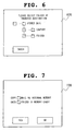
- Fig. 6 shows one example of the transfer destination folder selection screen 600 displayed on the LCD 12.
- This example shows the case where the transfer destination memory is the memory card, indicating that there are a folder named "stored mail" and two sub-folders named "company” and “friend” in its lower level.
- a user can select one of the folders with a cursor key on the key unit 11 and press the enter button to select a transfer destination folder.
- Step S112 When the folder is selected on the transfer destination folder selection screen 600, the controller 17 moves to a state where the selected folder is set as the transfer destination folder (Step S112).
- the controller 17 displays a confirmation screen 700 which makes a user confirm the selected transfer source folder and transfer destination folder on the LCD 12 to wait for user's input (Step S113).
- Fig. 7 shows one example of the confirmation screen 700 displayed on the LCD 12.
- This example shows the case where the access type is "write into the memory card" and selected as a transfer source folder is the "mail" folder of the internal memory 16 and selected as a transfer destination folder is the "friend" folder of the memory card 4.
- a user can press “YES” button or “NO” button displayed to instruct whether to execute this operation.
- Step S114 the controller 17 displays a message to this effect on the screen of the LCD 12 and when the data transfer is completed, a message to this effect is displayed.
- Access to the memory card 4 can be controlled by key operation of the key unit 11 of the portable terminal.
- the power source of the memory card 4 is not the portable terminal 1 but the AC adaptor 3, an increase in the power consumption of the portable terminal 1 can be prevented.
- data can be read and written from/to the memory card 4 while charging the battery pack 14, such a problem as data destruction can be prevented which is caused by power shut-off due to a dead battery during access to the memory card 4.
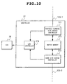
- a desktop holder 2a for a portable terminal 1a according to the second embodiment of the present invention is different in the following points from the desktop holder 2 according to the first embodiment shown in Fig. 1.
- the controller 27 provided on the desktop holder 2a includes a portable terminal side access controller 271, a card side access controller 272, a buffer memory 273 and an LED controller 274.
- the portable terminal side access controller 271 sends and receives data and a control signal to and from the controller 17 of the portable terminal 1a through the cable 103-1, the external interface terminal 242 of the third connector 24a and the external interface terminal 132 of the fourth connector 13a by a procedure according to the external interface.
- the portable terminal side access controller 271 then accumulates the data of the internal memory 16 received from the controller 17 into the buffer memory 273 at a time of writing into the memory card 4 and transfers the data of the memory card 4 accumulated into the buffer memory 273 to the controller 17 at a time of reading from the memory card 4.
- the card side access controller 272 sends and receives data and a control signal to and from the memory card 4 through the cable 103-2 and the external storage medium terminal 232 of the second connector 23 by a procedure according to the external storage medium interface.
- the card side access controller 272 then writes the data of the internal memory 16 accumulated in the buffer memory 273 into the memory card 4 at a time of wiring into the memory card and accumulates the data read out from the memory card 4 into the buffer memory 273 at a time of reading from the memory card.
- the portable terminal side access controller 271, the card side access controller 272 and the buffer memory 273 form an interface converting means between the external interface belonging to the portable terminal 1a and the external storage medium interface belonging to the memory card.
- the LED controller 274 is a unit which turns on the LED 28 during the operation of the portable terminal side access controller 271 and the card side access controller 272.
- the LED 28 is attached to the side surface of the desktop holder 2a so as to be seen from the outside of the holder, so that a user can check whether the memory card 4 is being accessed or not according to the state of the LED 28 being turned on or off.
- the operation in gaining access to the memory card 4 inserted in the slot 26 of the desktop holder 2a from the portable terminal 1a is the same as the operation in the first embodiment with the only difference being that the controller 27 of the desktop holder 2a performs the interface conversion as mentioned above.
- the fourth connector 13a of the portable terminal 1a since it is not necessary to provide the fourth connector 13a of the portable terminal 1a with an external storage medium terminal, the fourth connector 13a can be reduced in size.
- a desktop holder (2, 2a) includes a connector to be connected to a connector of a portable terminal (1, 1a) inserted into an insertion inlet (25), a connector to be connected to a memory card (4) inserted into a memory card slot (26), a cable (101, 102, 103, 103-1, 103-2) which connects connectors, and a connector which connects an AC adaptor, thereby enabling a battery pack (14) to be charged by the supply of charging DC voltage supplied from the AC adaptor to the portable terminal (1, 1a), as well as enabling the portable terminal (1, 1a) to read and write from/to the memory card (4) by key operation of the portable terminal (1, 1a).
Landscapes
- Engineering & Computer Science (AREA)
- Power Engineering (AREA)
- Human Computer Interaction (AREA)
- Computer Networks & Wireless Communication (AREA)
- Signal Processing (AREA)
- Charge And Discharge Circuits For Batteries Or The Like (AREA)
- Telephone Function (AREA)
- Telephone Set Structure (AREA)
- Secondary Cells (AREA)
- Mobile Radio Communication Systems (AREA)
Abstract
Description
Claims (13)
- A desktop holder (2, 2a) which accommodates a portable terminal (1, 1a), comprising:a connector which electrically connects an external storage medium inserted into an external storage medium slot (26) and an external connection terminal of the accommodated portable terminal (1, 1a) to enable read and write from/to said external storage medium by operation of said portable terminal (1, 1a) , anda connector which supplies charging DC voltage supplied from an AC adaptor (3) to said portable terminal (1, 1a) to charge a battery.
- The desktop holder (2, 2a) as set forth in claim 1, which includes, as contained in a case (10),
a first connector (21) having a charge terminal to be connected to an output terminal of the AC adaptor (3) which converts AC voltage of a commercial power source into charging DC voltage and outputs the obtained voltage,
a second connector (23) having an external storage medium terminal (232) to be connected to said external storage medium, and
a third connector (24, 24a) having a charge terminal to be connected to the external connection terminal of said portable terminal (1, 1a) and connected to said charge terminal of said first connector (21) and a terminal connected to said external storage medium terminal (232) of said second connector (23). - The desktop holder (2, 2a) as set forth in claim 2, wherein
said second connector (23) is provided in said external storage medium slot (26) provided in said case (10), and
said third connector (24, 24a) is provided in a portable terminal insertion inlet (25) provided in said case (10). - The desktop holder (2, 2a) as set forth in claim 2, further comprising:a regulator which receives input of said charging DC voltage from said charge terminal of said first connector (21) and converts the voltage into operating voltage to output the obtained voltage, whereinsaid second connector (23) includes a power source terminal (231) to which output of said regulator is applied.
- A portable terminal system having a portable terminal (1) and a desktop holder (2) for the portable terminal (1), wherein
said desktop holder (2) is internally provided with
a first connector (21) having a charge terminal to be connected to an output terminal of an AC adaptor which converts AC voltage of a commercial power source into charging DC voltage and outputs the obtained voltage,
a second connector (23) having an external storage medium terminal (232) to be connected to an external storage medium inserted into an external storage medium slot (26), and
a third connector (24) having a charge terminal to be connected to an external connection terminal of said portable terminal (1) and connected to said charge terminal of said first connector (21) and an external storage medium terminal (243) connected to said external storage medium terminal (232) of said second connector (23), and
said portable terminal (1) includes
a fourth connector (13) having a charge terminal and an external storage medium terminal (133) to be electrically and physically connected to said third connector (24),
a charging circuit (15) which receives input of said charging DC voltage from said charge terminal of said fourth connector (13) to charge a battery, and
control means which controls read and write from/to the external storage medium inserted into the external storage medium slot (26) of said desktop holder (2) to be connected through said external storage medium terminal (133) of said fourth connector (13). - The portable terminal system as set forth in claim 5, wherein
said second connector (23) is provided in said external storage medium slot (26) provided in said case (10) of said desktop holder (2), and
said third connector (24) is provided in a portable terminal insertion inlet (25) provided in said case (10) of said desktop holder (2). - The portable terminal system as set forth in claim 6, further comprising:a regulator which receives input of said charging DC voltage from said charge terminal of said first connector (21) and converts the voltage into operating voltage to output the obtained voltage, whereinsaid second connector (23) includes a power source terminal (231) to which output of said regulator is applied.
- The portable terminal system as set forth in any of claims 5 to 7, wherein
said control means of said portable terminal (1),
with either one of an internal memory (16) of said portable terminal (1) and the external storage medium inserted into said external storage medium slot (26) set to be a transfer source memory and the other set to be a transfer destination memory, displays a list of folders of the transfer source memory on a display device of said portable terminal (1) to select a transfer source folder by key operation and displays a list of folders of the transfer destination memory on said display device to make a user select a transfer destination folder by key operation, thereby reading data stored in said selected transfer source folder and writing the data into said selected transfer destination folder. - A portable terminal system having a portable terminal (1a) and a desktop holder (2a) for the portable terminal (1a), wherein
said desktop holder (2a) is internally provided with
a first connector (21) having a charge terminal to be connected to an output terminal of an AC adaptor which converts AC voltage of a commercial power source into charging DC voltage and outputs the obtained voltage,
a second connector (23) having an external storage medium terminal (232) to be connected to an external storage medium inserted into an external storage medium slot (26),
a third connector (24a) having a charge terminal connected to said charge terminal of said first connector (21) and an external interface terminal connected to said external storage medium terminal (232) of said second connector (23), and
control means having an interface conversion function of connecting said external storage medium terminal (232) of said second connector (23) and said external interface terminal, and
said portable terminal (1a) includes
a fourth connector (13a) having a charge terminal and an external interface terminal to be electrically and physically connected to said third connector (24a),
a charging circuit (15) which receives input of said charging DC voltage from said charge terminal of said fourth connector (13a) to charge a battery, and
control means which controls read and write from/to the external storage medium inserted into the external storage medium slot (26) of said desktop holder (2a) to be connected through said external storage medium terminal (133) of said fourth connector (13a). - The portable terminal system as set forth in claim 9, wherein
said second connector (23) is provided in said external storage medium slot (26) provided in said case (10) of said desktop holder (2a), and
said third connector (24a) is provided in a portable terminal insertion inlet (25) provided in said case (10) of said desktop holder (2a). - The portable terminal system as set forth in claim 10, further comprising:a regulator which receives input of said charging DC voltage from said charge terminal of said first connector (21) and converts the voltage into operating voltage to output the obtained voltage, whereinsaid second connector (23) includes a power source terminal (231) to which output of said regulator is applied.
- The portable terminal system as set forth in any of claims 9 to 11, wherein
said control means of said desktop holder (2a) includes
a portable terminal card side access controller (271), a card side access controller (272) and a buffer memory (273), and wherein
said portable terminal card side access controller (271)
sends and receives data and a control signal to/from said control means of said portable terminal (1a) through the external interface terminal of said third connector (24a) by a procedure according to the external interface and at the time of write to said external storage medium, accumulates, in said buffer memory (273), data of an internal memory (16) of said portable terminal (1a) received from said control means of said portable terminal (1a),
and at the time of read from said external storage medium, transfers the data of said external storage medium accumulated in said buffer memory (273) to said control means of said portable terminal (1a), and
said card side access controller (272)
sends and receives data and a control signal to/from said external storage medium through said external storage medium terminal (232) of said second connector (23) by a procedure according to the external storage medium interface and at the time of write to said external storage medium, writes data of said internal memory (16) accumulated in said buffer memory (273) into said external storage medium and at the time of read from said external storage medium, accumulates, in said buffer memory (273), data read from said external storage medium. - The portable terminal system as set forth in any of claims 9 to 12, wherein
said control means of said portable terminal (1a),
with either one of an internal memory (16) of said portable terminal (1a) and the external storage medium inserted into said external storage medium slot (26) set to be a transfer source memory and the other set to be a transfer destination memory, displays a list of folders of the transfer source memory on a display device of said portable terminal (1a) to select a transfer source folder by key operation and displays a list of folders of the transfer destination memory on said display device to make a user select a transfer destination folder by key operation, thereby reading data stored in said selected transfer source folder and writing the data into said selected transfer destination folder.
Applications Claiming Priority (2)
| Application Number | Priority Date | Filing Date | Title |
|---|---|---|---|
| JP2004065306 | 2004-03-09 | ||
| JP2004065306A JP2005258526A (en) | 2004-03-09 | 2004-03-09 | Desktop holder and portable terminal device system |
Publications (2)
| Publication Number | Publication Date |
|---|---|
| EP1583199A2 true EP1583199A2 (en) | 2005-10-05 |
| EP1583199A3 EP1583199A3 (en) | 2006-08-16 |
Family
ID=34879864
Family Applications (1)
| Application Number | Title | Priority Date | Filing Date |
|---|---|---|---|
| EP05101796A Withdrawn EP1583199A3 (en) | 2004-03-09 | 2005-03-08 | Desktop holder and portable terminal system |
Country Status (4)
| Country | Link |
|---|---|
| US (1) | US7426595B2 (en) |
| EP (1) | EP1583199A3 (en) |
| JP (1) | JP2005258526A (en) |
| CN (1) | CN100514980C (en) |
Cited By (3)
| Publication number | Priority date | Publication date | Assignee | Title |
|---|---|---|---|---|
| WO2009056559A1 (en) | 2007-10-30 | 2009-05-07 | Anil Goel | Cable with memory |
| EP2030461A4 (en) * | 2006-06-01 | 2010-06-02 | Clevx Llc | Information backup system for handheld devices |
| US8725924B2 (en) | 2006-06-01 | 2014-05-13 | Clevx, Llc | Information backup system with storing mechanism and method of operation thereof |
Families Citing this family (15)
| Publication number | Priority date | Publication date | Assignee | Title |
|---|---|---|---|---|
| US7783278B2 (en) * | 2006-03-15 | 2010-08-24 | Koninklijke Philips Electronics N.V. | Installation of a personal emergency response system |
| JP2007265340A (en) * | 2006-03-30 | 2007-10-11 | Softbank Mobile Corp | Data transfer device |
| US7764977B2 (en) * | 2006-05-24 | 2010-07-27 | Nokia Corporation | Memory card removal guard |
| US11068426B2 (en) * | 2006-08-31 | 2021-07-20 | Red Hat, Inc. | Portable storage device capable of transferring data to a portable storage device |
| KR100891770B1 (en) * | 2006-09-19 | 2009-04-07 | 삼성전자주식회사 | Push-up type portable charging cradle with stereo speaker system |
| JP2009123177A (en) * | 2007-11-11 | 2009-06-04 | E-Gensolution Co Ltd | Battery backup device |
| WO2009134455A1 (en) * | 2008-05-02 | 2009-11-05 | Byrne Norman R | Docking station |
| US8224380B2 (en) * | 2009-07-08 | 2012-07-17 | V.R. Technology Co., Ltd. | Structure of an apparatus for sharing video input/output modules among handheld devices |
| JP5821000B2 (en) * | 2009-08-24 | 2015-11-24 | パナソニックIpマネジメント株式会社 | Charging circuit |
| WO2011123619A2 (en) | 2010-03-31 | 2011-10-06 | Penguin Ip Holdings Inc. | Permeable mixtures, methods and compositions for the skin |
| TWD162302S (en) * | 2013-03-13 | 2014-08-11 | 星電股份有限公司 | Portable terminal charging base |
| US9429995B2 (en) | 2014-05-15 | 2016-08-30 | Norman R. Byrne | Docking station for electronic devices |
| JP6514866B2 (en) * | 2014-08-29 | 2019-05-15 | 株式会社マキタ | Rechargeable electric device |
| JP6533123B2 (en) * | 2015-08-20 | 2019-06-19 | シャープ株式会社 | Charging system |
| US10367362B2 (en) * | 2016-10-21 | 2019-07-30 | RLW Virtual Solutions, LLC | Disposable package assembly for batteries with added charging function |
Family Cites Families (34)
| Publication number | Priority date | Publication date | Assignee | Title |
|---|---|---|---|---|
| US5663901A (en) * | 1991-04-11 | 1997-09-02 | Sandisk Corporation | Computer memory cards using flash EEPROM integrated circuit chips and memory-controller systems |
| WO1995019030A1 (en) * | 1994-01-05 | 1995-07-13 | Pois, Inc. | Apparatus and method for a personal onboard information system |
| JP2823182B2 (en) | 1994-05-31 | 1998-11-11 | 日本電気株式会社 | Mobile phone equipment |
| JPH10334172A (en) | 1997-05-30 | 1998-12-18 | Tec Corp | Symbol reader |
| JPH11242653A (en) | 1998-02-24 | 1999-09-07 | Media Intelligent Kk | Pc card adapter |
| JP2000324237A (en) | 1999-03-10 | 2000-11-24 | Goddo:Kk | Charger with data backup function for mobile phone and data backup unit connected to the charger |
| US6757698B2 (en) * | 1999-04-14 | 2004-06-29 | Iomega Corporation | Method and apparatus for automatically synchronizing data from a host computer to two or more backup data storage locations |
| JP3522597B2 (en) * | 1999-08-02 | 2004-04-26 | 松下電器産業株式会社 | IC card connection device |
| JP3434751B2 (en) | 1999-11-11 | 2003-08-11 | エヌイーシーアクセステクニカ株式会社 | Mobile phone system |
| KR100313581B1 (en) * | 1999-12-15 | 2001-11-07 | 송문섭 | Docking station for cellular phone |
| JP2000216914A (en) | 2000-01-01 | 2000-08-04 | Nec Corp | Portable telephone device |
| JP2001202292A (en) | 2000-01-18 | 2001-07-27 | Sony Corp | Data backup device |
| JP3072497U (en) | 2000-04-13 | 2000-10-20 | 有限会社松和公産 | Memory adapter |
| US6832281B2 (en) * | 2000-07-06 | 2004-12-14 | Onspec Electronic Inc. | Flashtoaster for reading several types of flash memory cards with or without a PC |
| JP2002152401A (en) | 2000-11-15 | 2002-05-24 | Matsushita Electric Ind Co Ltd | Driver mobile terminal and luggage management method |
| US6725229B2 (en) * | 2000-12-29 | 2004-04-20 | Bellsouth Intellectual Property Corp. | Configuration utility |
| JP2002215275A (en) | 2001-01-15 | 2002-07-31 | Sony Corp | Electronic device and digital camera with USB connection function, file transfer method, and electronic device |
| GB2371638A (en) * | 2001-01-24 | 2002-07-31 | Hewlett Packard Co | Base station with data storage |
| JP2005057311A (en) | 2001-07-04 | 2005-03-03 | God Co Ltd | Data transfer device for connecting mobile phone charging adapter |
| US7152783B2 (en) * | 2001-07-10 | 2006-12-26 | Smart Card Integrators, Inc. | Combined card reader and bill acceptor |
| JP4249011B2 (en) * | 2001-07-18 | 2009-04-02 | データ・トランスファー・アンド・コミュニケーションズ・リミテッド | Data security device |
| JP2003044796A (en) | 2001-07-31 | 2003-02-14 | Sanyo Electric Co Ltd | Memory card reader and writer |
| US6754756B2 (en) * | 2001-08-08 | 2004-06-22 | Feiya Technology Corp. | GPS card reader |
| US7042950B2 (en) * | 2001-11-14 | 2006-05-09 | Matsushita Electric Industrial Co., Ltd. | Multichannel video processing unit and method |
| JP2003169156A (en) | 2001-11-29 | 2003-06-13 | Matsushita Electric Ind Co Ltd | Information devices for mobile devices |
| JP2003258991A (en) * | 2002-02-28 | 2003-09-12 | Seiko Epson Corp | Power supply means, information equipment and charging system |
| JP2003283610A (en) | 2002-03-26 | 2003-10-03 | Nec Saitama Ltd | Charger adapter |
| US7054624B2 (en) * | 2002-04-02 | 2006-05-30 | X-Cyte, Inc. | Safeguarding user data stored in mobile communications devices |
| US6950652B2 (en) * | 2003-01-08 | 2005-09-27 | Vtech Telecommunications Limited | Remote management of an external phonebook |
| US7724390B2 (en) * | 2003-02-14 | 2010-05-25 | Canon Kabushiki Kaisha | Selective access to memory cards |
| US20040234071A1 (en) * | 2003-05-08 | 2004-11-25 | Bae Hyon S. | Desktop phone station with data synchronization |
| JP2005011148A (en) * | 2003-06-20 | 2005-01-13 | Casio Comput Co Ltd | Download method, information receiving system, program and mobile phone |
| JP2005229454A (en) * | 2004-02-16 | 2005-08-25 | Fuji Photo Film Co Ltd | Cradle |
| EP1726097A4 (en) * | 2004-03-02 | 2007-09-05 | Spartak Buniatyan | Portable universal data storage device |
-
2004
- 2004-03-09 JP JP2004065306A patent/JP2005258526A/en active Pending
-
2005
- 2005-03-08 US US11/073,997 patent/US7426595B2/en not_active Expired - Fee Related
- 2005-03-08 EP EP05101796A patent/EP1583199A3/en not_active Withdrawn
- 2005-03-09 CN CNB2005100536382A patent/CN100514980C/en not_active Expired - Fee Related
Cited By (6)
| Publication number | Priority date | Publication date | Assignee | Title |
|---|---|---|---|---|
| EP2030461A4 (en) * | 2006-06-01 | 2010-06-02 | Clevx Llc | Information backup system for handheld devices |
| US8725924B2 (en) | 2006-06-01 | 2014-05-13 | Clevx, Llc | Information backup system with storing mechanism and method of operation thereof |
| WO2009056559A1 (en) | 2007-10-30 | 2009-05-07 | Anil Goel | Cable with memory |
| US8560865B2 (en) | 2007-10-30 | 2013-10-15 | Anil Goel | Cable with memory |
| US9287022B2 (en) | 2007-10-30 | 2016-03-15 | Meem Sl Limited | Cable with memory |
| US9729692B2 (en) | 2007-10-30 | 2017-08-08 | Meem Memory Limited | Cable with memory |
Also Published As
| Publication number | Publication date |
|---|---|
| CN1668043A (en) | 2005-09-14 |
| US7426595B2 (en) | 2008-09-16 |
| CN100514980C (en) | 2009-07-15 |
| JP2005258526A (en) | 2005-09-22 |
| US20050201049A1 (en) | 2005-09-15 |
| EP1583199A3 (en) | 2006-08-16 |
Similar Documents
| Publication | Publication Date | Title |
|---|---|---|
| US7426595B2 (en) | Desktop holder and portable terminal system | |
| DK2220564T3 (en) | CABLE WITH MEMORY | |
| US6664760B2 (en) | Cellular phone charger with data backup function and cellular phone data backup device | |
| JP3611735B2 (en) | Electronic connectors and adapters | |
| US7197584B2 (en) | Removable personal digital assistant in a dual personal computer/personal digital assistant computer architecture | |
| US6900980B2 (en) | Synchronization cradle with expansion card slots | |
| CN100474282C (en) | Memory card compatible with multiple connector standards | |
| US20120281356A1 (en) | Cases for tablet computers and methods | |
| WO2006026137A1 (en) | Memory device with hub capability | |
| US6477043B2 (en) | Data and power storage device | |
| EP1293876A1 (en) | A modular data processing system | |
| US8725924B2 (en) | Information backup system with storing mechanism and method of operation thereof | |
| CN100380278C (en) | Electric apparatus | |
| US20100078470A1 (en) | Media reader docking system | |
| US20070022232A1 (en) | Cellular telephone with integrated usb port engagement device that provides access to multimedia card as a solid-state device | |
| US20160041932A1 (en) | Memory storage with battery and solar cells | |
| JP2005057311A (en) | Data transfer device for connecting mobile phone charging adapter | |
| JP3403121B2 (en) | Battery built-in card adapter and charging device with adapter function | |
| KR200362446Y1 (en) | Memory Card Storage Device | |
| CN2935518Y (en) | Electronic Signal Connection System | |
| JP2001506780A (en) | Apparatus and method for adapting computer peripherals | |
| TWM307791U (en) | Electrical signal converting system | |
| EP1996992A2 (en) | An electrical apparatus for charging electrical devices | |
| HK1147823B (en) | Cable with memory | |
| JP2005115761A (en) | Memory card adapter |
Legal Events
| Date | Code | Title | Description |
|---|---|---|---|
| PUAI | Public reference made under article 153(3) epc to a published international application that has entered the european phase |
Free format text: ORIGINAL CODE: 0009012 |
|
| AK | Designated contracting states |
Kind code of ref document: A2 Designated state(s): AT BE BG CH CY CZ DE DK EE ES FI FR GB GR HU IE IS IT LI LT LU MC NL PL PT RO SE SI SK TR |
|
| AX | Request for extension of the european patent |
Extension state: AL BA HR LV MK YU |
|
| PUAL | Search report despatched |
Free format text: ORIGINAL CODE: 0009013 |
|
| AK | Designated contracting states |
Kind code of ref document: A3 Designated state(s): AT BE BG CH CY CZ DE DK EE ES FI FR GB GR HU IE IS IT LI LT LU MC NL PL PT RO SE SI SK TR |
|
| AX | Request for extension of the european patent |
Extension state: AL BA HR LV MK YU |
|
| 17P | Request for examination filed |
Effective date: 20070126 |
|
| AKX | Designation fees paid |
Designated state(s): DE FR GB IT |
|
| STAA | Information on the status of an ep patent application or granted ep patent |
Free format text: STATUS: THE APPLICATION HAS BEEN WITHDRAWN |
|
| 18W | Application withdrawn |
Effective date: 20150223 |