EP1583193B1 - Optimierungsverfahren einer elektrischen Verdrahtung, insbesondere in der Aeronautik - Google Patents
Optimierungsverfahren einer elektrischen Verdrahtung, insbesondere in der Aeronautik Download PDFInfo
- Publication number
- EP1583193B1 EP1583193B1 EP05290647A EP05290647A EP1583193B1 EP 1583193 B1 EP1583193 B1 EP 1583193B1 EP 05290647 A EP05290647 A EP 05290647A EP 05290647 A EP05290647 A EP 05290647A EP 1583193 B1 EP1583193 B1 EP 1583193B1
- Authority
- EP
- European Patent Office
- Prior art keywords
- cables
- cable
- line
- optimization method
- accordance
- Prior art date
- Legal status (The legal status is an assumption and is not a legal conclusion. Google has not performed a legal analysis and makes no representation as to the accuracy of the status listed.)
- Expired - Lifetime
Links
- 238000000034 method Methods 0.000 title claims abstract description 34
- 238000005457 optimization Methods 0.000 title claims description 31
- 238000009429 electrical wiring Methods 0.000 title description 4
- 238000004590 computer program Methods 0.000 claims abstract description 6
- 230000007613 environmental effect Effects 0.000 claims description 5
- 230000003287 optical effect Effects 0.000 claims description 2
- 238000013500 data storage Methods 0.000 claims 1
- 238000004364 calculation method Methods 0.000 description 8
- 238000004422 calculation algorithm Methods 0.000 description 7
- 238000005516 engineering process Methods 0.000 description 6
- RYGMFSIKBFXOCR-UHFFFAOYSA-N Copper Chemical compound [Cu] RYGMFSIKBFXOCR-UHFFFAOYSA-N 0.000 description 5
- XAGFODPZIPBFFR-UHFFFAOYSA-N aluminium Chemical compound [Al] XAGFODPZIPBFFR-UHFFFAOYSA-N 0.000 description 5
- 229910052782 aluminium Inorganic materials 0.000 description 5
- 229910052802 copper Inorganic materials 0.000 description 5
- 239000010949 copper Substances 0.000 description 5
- 239000000463 material Substances 0.000 description 5
- 230000035882 stress Effects 0.000 description 5
- 230000008646 thermal stress Effects 0.000 description 5
- 239000004020 conductor Substances 0.000 description 3
- 238000000354 decomposition reaction Methods 0.000 description 2
- 238000013461 design Methods 0.000 description 2
- 238000010586 diagram Methods 0.000 description 2
- 230000005684 electric field Effects 0.000 description 2
- 238000010438 heat treatment Methods 0.000 description 2
- 238000009413 insulation Methods 0.000 description 2
- 239000012212 insulator Substances 0.000 description 2
- 230000000717 retained effect Effects 0.000 description 2
- 206010063493 Premature ageing Diseases 0.000 description 1
- 208000032038 Premature aging Diseases 0.000 description 1
- 238000004458 analytical method Methods 0.000 description 1
- 230000001143 conditioned effect Effects 0.000 description 1
- 238000011109 contamination Methods 0.000 description 1
- 238000001816 cooling Methods 0.000 description 1
- 238000013480 data collection Methods 0.000 description 1
- 230000007423 decrease Effects 0.000 description 1
- 238000009795 derivation Methods 0.000 description 1
- 238000011161 development Methods 0.000 description 1
- 230000018109 developmental process Effects 0.000 description 1
- 230000000694 effects Effects 0.000 description 1
- 238000010616 electrical installation Methods 0.000 description 1
- 230000005611 electricity Effects 0.000 description 1
- 238000011156 evaluation Methods 0.000 description 1
- 239000000835 fiber Substances 0.000 description 1
- 239000000446 fuel Substances 0.000 description 1
- 238000002955 isolation Methods 0.000 description 1
- 238000013021 overheating Methods 0.000 description 1
- 238000000926 separation method Methods 0.000 description 1
Images

Classifications
-
- B—PERFORMING OPERATIONS; TRANSPORTING
- B60—VEHICLES IN GENERAL
- B60R—VEHICLES, VEHICLE FITTINGS, OR VEHICLE PARTS, NOT OTHERWISE PROVIDED FOR
- B60R16/00—Electric or fluid circuits specially adapted for vehicles and not otherwise provided for; Arrangement of elements of electric or fluid circuits specially adapted for vehicles and not otherwise provided for
- B60R16/02—Electric or fluid circuits specially adapted for vehicles and not otherwise provided for; Arrangement of elements of electric or fluid circuits specially adapted for vehicles and not otherwise provided for electric constitutive elements
- B60R16/0207—Wire harnesses
Definitions
- the present invention relates to a method for optimizing electrical wiring, particularly in the aeronautical field.
- Document US-2003/0047997 relates to a data collection network and an electrical power distribution system for reducing the weight of wires in an aircraft.
- the purpose of the present invention is therefore to provide means making it possible, for a given aircraft, to limit the mass of electrical cables necessary for wiring the various systems of the aircraft without, however, limiting their number and / or their location.
- the section of the cables is dimensioned for each cable of the line independently of the other cables and optimized taking into account the global constraints of the line.
- the invention proposes here not to consider a line connecting a power source to a receiving equipment as a line of constant section but as a line of variable section. In this way, it is possible to limit the section of the cables used on certain portions of the line when it is not possible to have a reduced section over the entire line.
- the invention proposes in a preferred embodiment that prior to the determining the section of the cables used, the routing of lines and cables for calculating a path to be taken by the various lines and cables is performed.
- the knowledge of the path taken by the cables allows a better optimization of the line because it is then possible to determine the type of cable used (shielded or not, resistant to such or such temperature, etc.).
- this routing of the lines and cables preferably makes it possible to determine the at least approximate position of the jacks separating two adjacent cables. In this way, the length of each cable is known and the mass of the cables can be better determined.
- an optimization method for at least one cable of a line, several cable sections that can be used according to the constraints imposed on this cable are determined; these cables are combined in various combinations to form a line; it is checked for each line if the global constraints of the line are satisfied, and the line answering the global and lower mass technical constraints is selected.
- the term variety is used here to distinguish itself from the "type" of cable described below.
- the type of cable gives its general structure (in the electrical field, there are for example shielded or unshielded cables, with one or more wires, with an insulator of such or such nature, etc.).
- the variety here also concerns the section of the cable. Thus two cables of the same variety have both the same section and are of the same type.
- the optimization of the overall mass of the cables is preferably performed on two discrete variables, the type and section of the cables.
- the present invention is particularly adapted to be applied to the realization of electrical wiring.
- the predetermined constraints comprise for example a maximum intensity value defined by among others the consumption of a load and a maximum allowed voltage drop.
- the environmental constraints include, for example, the surrounding temperature.
- the drawing illustrates the use of a method according to the invention for producing an electrical wiring of an aircraft.
- a similar process can be used in applications other than aeronautics.
- the following description shows how, according to the invention, it is possible to reduce the overall weight of the cables of an electrical network.
- the increase in the number of onboard systems as well as the increase in the power consumed by the equipment of the aircraft leads to an increase in the mass of electrical installations of the aircraft.
- the invention proposes to optimize the mass of cables connecting the various embedded systems and power equipment.
- the optimized electrical network obtained must meet all safety standards without affecting the power consumed, the number of embedded systems, or even their location.
- the type and gauge of the C1 cable should now be determined.
- the type of an electric cable is codified.
- the indication of the type of a cable makes it possible to know in particular the number of conductors constituting the cable, the material used for producing the conductors, the nature of the insulation and the possible presence and nature of a shielding. .
- the gauge of a cable, symbolized by the # sign is expressed according to the AWG (American Wire Gauge) standard. The value of the gauge decreases when the driver section, and therefore its ohmic resistance, increases.
- the maximum wire gauge (ie minimum section) for C1 cable is # 8 in aluminum technology and # 10 in copper technology. Taking into account the various constraints ( ⁇ V for example) and being careful not to unnecessarily increase the mass of the cables, one then chooses a gauge cable # 4.
- the present invention proposes a new and original way of defining an electrical network, as described below.
- the position of the equipment being defined it constitutes the electrical harnesses by determining in particular their length. It is then possible to carry out the routing of the functional links.
- the gauges and cable types are calculated. All the electrical, technological (cable material, connectors, ...) and thermal constraints are taken into account to ensure the correct and just dimensioning of the cables. Note that here the cable gauges are calculated after routing them. The determination of the gauges of the various cables is then optimized to reduce the overall mass of the cable network. The present invention relates in particular to this last step of determining the gauge of the cables and the optimization thereof.
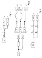
- An electricity grid is a collection of several sources related to several loads, these sources and these loads being connected by cables possibly using components (circuit breaker, diode, etc.).
- a line is a related subset of a single source, single load network with one or more cables and possibly one or more components.
- a line is a unique combination of cables and equipotentials connecting the source to the load.
- the figure 2 illustrates the decomposition of a simple network into several lines. Each line has a source and a load. We can thus first of all consider the source S and the load Ch1. Note that two separate electrical paths connect the source S to the load Ch1. So we have to consider two power lines that are called, on the right of the figure 2 , L1 and L2. Considering then the source S and the load Ch2, we note that a single electrical path connects these two elements. This path thus forms the line called L3.
- the cable gauge must be compatible with the circuit breaker rating to protect the line before it is flowing through a current that causes it to overheat to a critical temperature. It is also necessary, in order to allow a good operation of the equipment, to limit voltage drops in line ( ⁇ Vmax). These voltage drops are determined beforehand according to the equipment supplied by the source.
- the insulators used for the cables do not all withstand the same temperatures.
- the choice of insulation will be mainly conditioned by the thermal constraints.
- the material conductor (aluminum or copper) in an aircraft depends on the area of the aircraft to which the cable is intended. Indeed, to avoid possible contamination, the use of aluminum cables is limited to certain areas of the aircraft.
- Specific constraints for example use of a shielded three-wire cable
- the type of cables to be used It is also necessary to take into account the admissible radius of curvature by the cable during its use. This prohibits the use of certain types of cables in confined spaces.
- the type of cable chosen must also take into account the connector to which it must be connected.
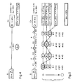
- the figure 5 illustrates the choice of cable gages on a line by taking over the source S and the load Ch of the figure 4 .
- C1, C2, C3 and C4 These cables measure respectively 2m, 18m, 30m and 10m.
- EL total length
- each cable C1 to C4 has been shown to show the various gauges that are a priori acceptable. These gauges are classified by their increasing mass indicated by the arrow on the left of the figure.
- the preferred combination retained here is a # 8 gauge cable C1, a # 4 gauge cable C2, a # 6 gauge cable C3 and a # 4 gauge cable C4.
- This combination gives a maximum voltage drop ⁇ V of 3.84V for a mass of 10.44kg. It is thus noted that the difference in cable mass between this preferential combination and the calculation of the cable gages of the prior art is 22%.
- the Figures 6 to 8 illustrate this optimized determination of the cable gages.
- the type t of the cables is represented on the abscissa and the gauge # on the ordinate.
- the gauge # on the ordinate.
- it represents all types and cable gauges that may be suitable when taking into account only the constraints concerning the current to flow in the cable, the environment in which the cable is (copper or aluminum), the thermal stresses, and also the constraints on connection. We then obtain a large number of possibilities. In the example of the figure 5 , they correspond to all the cable gages indicated. Once these valid cables have been selected, it must be verified that in terms of voltage drop the specifications are respected. The choice of cables is then limited as illustrated by figure 7 . Finally, when optimizing the mass of the cables, only a few cables can be retained, as shown on the diagram. figure 8 .
- the problem of mass optimization is a problem of discrete optimization (gauges / types of cables) under stress (voltage drop in line).
- the difficulty of such a problem increases considerably when the optimization is no longer on a line but on a network.
- Such a network can be schematized for example as on the figure 3 .
- a source S associated with a circuit breaker is connected to several charges Ch1 to Chn thus forming a set of lines L1 to Ln.
- the figure 9 shows in schematic form a calculation algorithm to obtain an optimization of the gauges and types of cables in a network.
- This database D symbolizes the various information available concerning the architecture of the aircraft. They are not necessarily grouped in the same physical database. It may even be assumed that some of the information required for the calculation explained below is not available in digital form but must be entered.
- the function F1 makes it possible to constitute the lines. From a switched network such as that of the figure 1 This F1 function automatically selects the different states of the switching components and thus searches for all the components making it possible to constitute a power line.
- the function F2 calculates, for each component of the line, the maximum currents Imax, in particular to size the cables in temperature and calculate the size of the circuit breaker.
- Function F3 calculates / checks the rating of the circuit breaker. If circuit breaker technology has not been specified, at this function F3 the circuit breaker with the minimum ohmic resistance is selected. It is already possible to calculate here the cable gauges compatible with the circuit breaker rating.
- the function F4 calculates the most constraining environment to which a predetermined cable is subjected.
- Business rules defined by a standard, require a choice of cable types and gauges depending on the airplane environment in which the cable travels. The same cable can cross aircraft zones of different characteristics (pressurized zone or not, different ambient temperature, etc ). Here we also obtain a set of compatible types / cable gages.
- the function F5 makes it possible to calculate the thermal stresses. This calculation is already done in the state of the art. Depending on the input data, different methods can be used. It is simply recalled here that the thermal stresses depend essentially on the maximum ambient temperature, the intensity of current flowing through the cable and also on its position in the aircraft.
- Function F6 calculates the connection constraints.
- the user of the system implementing the algorithm of the figure 9 has access for example to a table listing the connection elements that can be used. Based on these selected elements, the F6 function calculates the cable types / gauges compatible.
- the level of this function F6 a graphical interface allowing the user to visualize the elements of connections selected.
- Fibers are subsequently calculated (function F7) for the dimensioning of the cables under the stress ⁇ Vmax.
- the cable is then no longer considered here in isolation but as an element of the line Li in which it is integrated and where it contributes to a voltage drop ⁇ Vi.
- the value Idim i corresponds to the intensity of the current causing the maximum voltage drop ⁇ Vi.
- the function F8 makes it possible to calculate the maximum voltage drop allowed in the cables while also considering the intermediate voltage drops due to the presence of components (circuit-breaker, diode, etc.).
- the function F9 determines, before optimization, the valid types / cable gauges. According to the set of previously defined constraints, the function F9 calculates the valid solutions (types / gauges) for each of the cables of the network. It is verified here that for each of the cables of a line, the maximum voltage drop stress ( ⁇ Vmax) is not exceeded. In this way, we reduce the set of input solutions of the optimization algorithm.
- function F10 is the function for optimizing cable types / gauges.
- the functions F1 to F8 make it possible to determine the set of acceptable pairs / gages of the figure 6 .
- the function F9 makes it possible to switch to the type / gauge pairs represented on the figure 7 .
- the optimization function F10 makes it possible to retain only the types and gauges of the figure 8 .
- the goal of the optimization problem is to minimize the mass of the network.
- a second constraint is related to the Imax value.
- the maximum gauge is restricted by the corresponding circuit breaker rating as well as the Joule heating stress of the cable.
- this restriction is not the same depending on the material used for the cable. Since the material is related to the type of cable, the two variables are used here in this constraint.
- all sections are not available and there may also exist another constraint due to the connections. For each cable, it can therefore be said that its section (corresponding to its gauge) is greater (or equal) than a minimum section depending on the type of cable and the connectors and lower (or equal) to a maximum cross-sectional area of the circuit breaker, of the heating, the type of cable and the connections.
- a personal computer can be used for the implementation of this method. Programming on a conventional spreadsheet software can even be considered.
- the optimization of gauges and cable types is performed considering all segments of a functional link and not just a single link between two devices.
- the method described above makes it possible to dimension the cables automatically.
- this dimensioning is a complex exercise that requires a deep professional practice of the design profession.
- cumbersome and cumbersome calculations are required to resize the cables.
- Such a problem is frequently encountered during the development of a new aircraft.
- the definition of electrical harnesses is brought to evolve very regularly during the design of this new aircraft.
- the automatic calculation proposed by the invention makes it possible to quickly measure the effects of a routing evolution or a change of technology on the cable gages and to validate also that all the constraints are respected.
Landscapes
- Engineering & Computer Science (AREA)
- Mechanical Engineering (AREA)
- Electric Cable Installation (AREA)
- Supply And Distribution Of Alternating Current (AREA)
- Internal Circuitry In Semiconductor Integrated Circuit Devices (AREA)
- Testing Of Short-Circuits, Discontinuities, Leakage, Or Incorrect Line Connections (AREA)
- Installation Of Indoor Wiring (AREA)
Claims (11)
- Verfahren zur Optimierung einer Verkabelung, bei dem die Merkmale der Kabel, die zur Verbindung einer Quelle (S) mit einer empfangenden Last (Ch) verwendet werden, in Abhängigkeit von vorbestimmten Bedingungen und von Umgebungs bedingungen definiert sind,
dadurch gekennzeichnet, dass in den Fällen, in denen eine Leitung (Li), die die Verbindung zwischen der Quelle (S) und der empfangenden Last (Ch) herstellt, mehrere gesonderte, durch Trennstecker (P) verbundene Kabel (Ci) umfasst, der Querschnitt der Kabel bei jedem Kabel (Ci) der Leitung unabhängig von den anderen Kabeln dimensioniert und dann optimiert wird, indem die Gesamtbedingungen der Leitung (Li) berücksichtigt werden. - Optimierungsverfahren nach Anspruch 1, dadurch gekennzeichnet, dass vor der Bestimmung des Querschnitts der verwendeten Kabel (Ci) das Routing der Leitungen (Li) und Kabel (i) durchgeführt wird, das es gestattet, einen von den einzelnen Leitungen und Kabeln zu nehmenden Weg zu berechnen.
- Optimierungsverfahren nach Anspruch 2, dadurch gekennzeichnet, dass das Routing der Leitungen und Kabel es gestattet, die mindestens annähernde Lage der zwei benachbarte Kabel (Ci) trennenden Trennstecker (P) zu bestimmen.
- Optimierungsverfahren nach einem der Ansprüche 1 bis 3, dadurch gekennzeichnet, dass für mindestens ein Kabel (Ci) einer Leitung mehrere verwendbare Kabelquerschnitte in Abhängigkeit von den von diesem Kabel (Ci) zu erfüllenden Bedingungen bestimmt werden, dass diese Kabel (Ci) in verschiedenen Kombinationen zur Bildung einer Leitung kombiniert werden, dass bei jeder Leitung nachgeprüft wird, ob die Gesamtbedingungen der Leitung erfüllt werden, und dass die den technischen Gesamtbedingungen entsprechende Leitung mit der kleinsten Masse ausgewählt wird.
- Optimierungsverfahren nach einem der Ansprüche 1 bis 4, dadurch gekennzeichnet, dass alle Merkmale der verschiedenen Sorten von Kabeln, die zur Herstellung der betreffenden Verkabelung verwendet werden können, in einer Datenbasis (D) gespeichert werden.
- Optimierungsverfahren nach einem der Ansprüche 1 bis 5, dadurch gekennzeichnet, dass die Optimierung der Gesamtmasse der Kabel an zwei diskreten Variablen, dem Typ und dem Querschnitt der Kabel, vorgenommen wird.
- Optimierungsverfahren nach einem der Ansprüche 1 bis 6, dadurch gekennzeichnet, dass es auf die Herstellung einer elektrischen Verkabelung angewandt wird.
- Optimierungsverfahren nach Anspruch 7, dadurch gekennzeichnet, dass die vorbestimmten Bedingungen einen durch einen Ausschalter definierten I-iöchststromstärkewert und einen maximal zulässigen Spannungsabfall umfassen.
- Optimierungsverfahren nach einem der Ansprüche 7 oder 8, dadurch gekennzeichnet, dass die Umgebungsbedingurlgen die Umgebungstemperatur umfassen.
- Auf einem Datenträger gespeichertes Rechnerprogramm, wobei dieses Programm Befehle umfasst, die die Durchführung eines Optimierungsverfahrens nach einem der Ansprüche 1 bis 9 gestatten, wenn das Programm geladen und von einem Informatiksystem ausgeführt wird.
- Durch ein Informatiksystem lesbarer, gegebenenfalls vollständig oder teilweise abnehmbarer Datenträger, insbesondere CD-ROM, DVD-ROM oder Magnetträger, wie eine Festplatte oder eine Diskette, oder übertragbarer Träger, wie ein elektrisches oder optisches Signal, dadurch gekennzeichnet, dass es Befehle eines Rechnerprogramms umfasst, das die Durchführung eines Verfahrens nach einem der Ansprüche 1 bis 9 gestatten, wenn dieses Programm geladen und von einem Informatiksystem ausgeführt wird.
Applications Claiming Priority (2)
| Application Number | Priority Date | Filing Date | Title |
|---|---|---|---|
| FR0403468 | 2004-04-02 | ||
| FR0403468A FR2868573B1 (fr) | 2004-04-02 | 2004-04-02 | Procede d'optimisation d'un cablage electrique, notamment dans le domaine aeronautique |
Publications (2)
| Publication Number | Publication Date |
|---|---|
| EP1583193A1 EP1583193A1 (de) | 2005-10-05 |
| EP1583193B1 true EP1583193B1 (de) | 2010-08-25 |
Family
ID=34878486
Family Applications (1)
| Application Number | Title | Priority Date | Filing Date |
|---|---|---|---|
| EP05290647A Expired - Lifetime EP1583193B1 (de) | 2004-04-02 | 2005-03-24 | Optimierungsverfahren einer elektrischen Verdrahtung, insbesondere in der Aeronautik |
Country Status (6)
| Country | Link |
|---|---|
| US (1) | US7676771B2 (de) |
| EP (1) | EP1583193B1 (de) |
| AT (1) | ATE479220T1 (de) |
| CA (1) | CA2498732C (de) |
| DE (1) | DE602005023089D1 (de) |
| FR (1) | FR2868573B1 (de) |
Families Citing this family (8)
| Publication number | Priority date | Publication date | Assignee | Title |
|---|---|---|---|---|
| FR2900292B1 (fr) | 2006-04-21 | 2008-11-14 | Airbus France Sas | Dispositif de securite pour interrupteur a semi-conducteurs |
| US20100052642A1 (en) * | 2008-08-26 | 2010-03-04 | Broadcom Corporation | System and method for using a phy's discovery of cable shielding for power over ethernet current capacity setting and temperature de-rating |
| FR2970579B1 (fr) * | 2011-01-13 | 2013-01-11 | Peugeot Citroen Automobiles Sa | Dispositif et procede de calcul de sections optimales de troncons d'au moins une ligne electrique en fonction de la chute de tension maximale autorisee sur cette ligne |
| FR3012661B1 (fr) * | 2013-10-28 | 2015-12-04 | Labinal | Procede de caracterisation d'un toron de cables electriques |
| CN107370146B (zh) * | 2017-06-06 | 2020-07-17 | 国网江西省电力公司萍乡供电分公司 | 一种计及风随机性影响的直线塔输电线路风偏放电概率在线预警方法 |
| CN111046488B (zh) * | 2019-11-25 | 2023-07-25 | 北京空间技术研制试验中心 | 航天器电缆三维布线方法 |
| CN114237076B (zh) * | 2021-12-17 | 2023-12-12 | 北京理工大学 | 一种基于位置动力学的活动线缆运动仿真的方法及控制器 |
| CN114615149B (zh) * | 2022-05-12 | 2022-08-02 | 南昌航空大学 | 一种飞行器多动力系统数据交互网络结构优化方法 |
Family Cites Families (9)
| Publication number | Priority date | Publication date | Assignee | Title |
|---|---|---|---|---|
| JPH11272727A (ja) * | 1998-03-23 | 1999-10-08 | Hitachi Plant Eng & Constr Co Ltd | 配線経路設計支援方法 |
| FR2791475B1 (fr) * | 1999-03-23 | 2007-02-23 | Sagem | Cable rayonnant |
| DE19935422A1 (de) * | 1999-07-28 | 2001-02-01 | Daimler Chrysler Ag | Verfahren zur Erzeugung einer Leitungsstruktur mit wenigstens einem Kabelbündel |
| WO2001024111A1 (en) * | 1999-09-30 | 2001-04-05 | Routech, Inc. | Automatic routing system for pc board design |
| US6664656B2 (en) * | 2000-09-14 | 2003-12-16 | The Boeing Company | Aircraft electrical power distribution network |
| US6886152B1 (en) * | 2002-08-09 | 2005-04-26 | Xilinx, Inc. | Delay optimization in signal routing |
| US7194720B1 (en) * | 2003-07-11 | 2007-03-20 | Altera Corporation | Method and apparatus for implementing soft constraints in tools used for designing systems on programmable logic devices |
| US7057734B2 (en) * | 2003-07-23 | 2006-06-06 | Honeywell International Inc. | Integrated reaction wheel assembly and fiber optic gyro |
| US7100142B2 (en) * | 2004-04-07 | 2006-08-29 | Synopsys, Inc. | Method and apparatus for creating a mask-programmable architecture from standard cells |
-
2004
- 2004-04-02 FR FR0403468A patent/FR2868573B1/fr not_active Expired - Fee Related
-
2005
- 2005-03-01 CA CA2498732A patent/CA2498732C/fr not_active Expired - Fee Related
- 2005-03-24 EP EP05290647A patent/EP1583193B1/de not_active Expired - Lifetime
- 2005-03-24 DE DE602005023089T patent/DE602005023089D1/de not_active Expired - Lifetime
- 2005-03-24 AT AT05290647T patent/ATE479220T1/de not_active IP Right Cessation
- 2005-04-04 US US11/097,276 patent/US7676771B2/en not_active Expired - Fee Related
Also Published As
| Publication number | Publication date |
|---|---|
| FR2868573B1 (fr) | 2006-06-23 |
| US20050271350A1 (en) | 2005-12-08 |
| FR2868573A1 (fr) | 2005-10-07 |
| EP1583193A1 (de) | 2005-10-05 |
| US7676771B2 (en) | 2010-03-09 |
| ATE479220T1 (de) | 2010-09-15 |
| CA2498732A1 (fr) | 2005-10-02 |
| DE602005023089D1 (de) | 2010-10-07 |
| CA2498732C (fr) | 2015-06-16 |
Similar Documents
| Publication | Publication Date | Title |
|---|---|---|
| EP1583193B1 (de) | Optimierungsverfahren einer elektrischen Verdrahtung, insbesondere in der Aeronautik | |
| EP3406014B1 (de) | System und verfahren zur dynamischen bestimmung von maximalen elektrischen stromtragfähigkeiten | |
| CA2911222C (fr) | Gaine de protection d'un harnais electrique afin de prevenir sa deterioration | |
| CA2927711C (fr) | Procede de caracterisation d'un toron de cables electriques | |
| CA2576916C (fr) | Procede et dispositif de detection d'un phenomene d'arc electrique sur au moins un cable electrique | |
| EP2629998B1 (de) | Vorrichtung und verfahren zur kalkulation eines berührungsstroms und schutz einer elektrischen vorrichtung vor derartigen berührungsströmen | |
| FR3052364A1 (fr) | Systeme d'alimentation electrique d'un appareil teleopere captif | |
| EP4490525B1 (de) | Detektion eines lichtbogens mittels eines bragg-gitters | |
| FR2997508A1 (fr) | Harnais et cable comportant une pluralite de capteurs elementaires et procede de surveillance d'un cable et d'un harnais | |
| EP3590121B1 (de) | Redundantes und unähnliches system zur überwachung des status von steuerschützen eines flugzeugsteuerknüppels | |
| CA2346313C (fr) | Systeme de transport et de distribution d'energie electrique | |
| FR2983175A1 (fr) | Cablage d'un panneau de disjoncteurs d'avion | |
| FR3145656A1 (fr) | Procédé de surveillance et de protection d’un système d’hybridation électrique contre le risque de feu | |
| EP2342793B1 (de) | Elektrische netzwerkarchitektur für eingegrenzte umgebungen mit elektrischen stromquellen | |
| EP0964256A1 (de) | Verfahren und Vorrichtung zur Ortung von Kurzschlüssen in einem Bus eines Multiplexnetzwerks zur Informationsübertragung | |
| FR3085154A1 (fr) | Procede de maintenance d’un systeme de distribution electrique | |
| FR3063839B1 (fr) | Systeme de protection contre la foudre pour un aeronef | |
| WO2020039143A1 (fr) | Procédé d'auto-configuration d'une carte électronique autonome de disjoncteurs statiques | |
| EP4392798B1 (de) | Verfahren zur überprüfung einer vorrichtung zur prüfung einer hilfsbatterie | |
| Lu | Analysis of the coupling effects on main feeder in more electrical aircraft | |
| FR3076670A1 (fr) | Reseau d'alimentation electrique et procede de commande associe | |
| FR3073099A1 (fr) | Boitier de distribution electrique et de concentration de donnees pour aeronef. | |
| WO2026057949A1 (fr) | Système d'hybridation électrique avec fonction de filtrage intégrée | |
| FR3153926A1 (fr) | Câble électrique de puissance haute fréquence et haute tension | |
| FR2908907A1 (fr) | Procede de modelisation d'un reseau d'alimentation electrique pour vehicule automobile |
Legal Events
| Date | Code | Title | Description |
|---|---|---|---|
| PUAI | Public reference made under article 153(3) epc to a published international application that has entered the european phase |
Free format text: ORIGINAL CODE: 0009012 |
|
| AK | Designated contracting states |
Kind code of ref document: A1 Designated state(s): AT BE BG CH CY CZ DE DK EE ES FI FR GB GR HU IE IS IT LI LT LU MC NL PL PT RO SE SI SK TR |
|
| AX | Request for extension of the european patent |
Extension state: AL BA HR LV MK YU |
|
| 17P | Request for examination filed |
Effective date: 20060330 |
|
| AKX | Designation fees paid |
Designated state(s): AT BE BG CH CY CZ DE DK EE ES FI FR GB GR HU IE IS IT LI LT LU MC NL PL PT RO SE SI SK TR |
|
| GRAP | Despatch of communication of intention to grant a patent |
Free format text: ORIGINAL CODE: EPIDOSNIGR1 |
|
| GRAS | Grant fee paid |
Free format text: ORIGINAL CODE: EPIDOSNIGR3 |
|
| GRAA | (expected) grant |
Free format text: ORIGINAL CODE: 0009210 |
|
| RAP1 | Party data changed (applicant data changed or rights of an application transferred) |
Owner name: AIRBUS OPERATIONS |
|
| AK | Designated contracting states |
Kind code of ref document: B1 Designated state(s): AT BE BG CH CY CZ DE DK EE ES FI FR GB GR HU IE IS IT LI LT LU MC NL PL PT RO SE SI SK TR |
|
| REG | Reference to a national code |
Ref country code: GB Ref legal event code: FG4D Free format text: NOT ENGLISH |
|
| REG | Reference to a national code |
Ref country code: CH Ref legal event code: EP |
|
| REG | Reference to a national code |
Ref country code: IE Ref legal event code: FG4D Free format text: LANGUAGE OF EP DOCUMENT: FRENCH |
|
| REF | Corresponds to: |
Ref document number: 602005023089 Country of ref document: DE Date of ref document: 20101007 Kind code of ref document: P |
|
| REG | Reference to a national code |
Ref country code: NL Ref legal event code: VDEP Effective date: 20100825 |
|
| LTIE | Lt: invalidation of european patent or patent extension |
Effective date: 20100825 |
|
| PG25 | Lapsed in a contracting state [announced via postgrant information from national office to epo] |
Ref country code: AT Free format text: LAPSE BECAUSE OF FAILURE TO SUBMIT A TRANSLATION OF THE DESCRIPTION OR TO PAY THE FEE WITHIN THE PRESCRIBED TIME-LIMIT Effective date: 20100825 Ref country code: FI Free format text: LAPSE BECAUSE OF FAILURE TO SUBMIT A TRANSLATION OF THE DESCRIPTION OR TO PAY THE FEE WITHIN THE PRESCRIBED TIME-LIMIT Effective date: 20100825 Ref country code: LT Free format text: LAPSE BECAUSE OF FAILURE TO SUBMIT A TRANSLATION OF THE DESCRIPTION OR TO PAY THE FEE WITHIN THE PRESCRIBED TIME-LIMIT Effective date: 20100825 |
|
| PG25 | Lapsed in a contracting state [announced via postgrant information from national office to epo] |
Ref country code: IS Free format text: LAPSE BECAUSE OF FAILURE TO SUBMIT A TRANSLATION OF THE DESCRIPTION OR TO PAY THE FEE WITHIN THE PRESCRIBED TIME-LIMIT Effective date: 20101225 Ref country code: BG Free format text: LAPSE BECAUSE OF FAILURE TO SUBMIT A TRANSLATION OF THE DESCRIPTION OR TO PAY THE FEE WITHIN THE PRESCRIBED TIME-LIMIT Effective date: 20101125 Ref country code: CY Free format text: LAPSE BECAUSE OF FAILURE TO SUBMIT A TRANSLATION OF THE DESCRIPTION OR TO PAY THE FEE WITHIN THE PRESCRIBED TIME-LIMIT Effective date: 20100825 Ref country code: PL Free format text: LAPSE BECAUSE OF FAILURE TO SUBMIT A TRANSLATION OF THE DESCRIPTION OR TO PAY THE FEE WITHIN THE PRESCRIBED TIME-LIMIT Effective date: 20100825 Ref country code: PT Free format text: LAPSE BECAUSE OF FAILURE TO SUBMIT A TRANSLATION OF THE DESCRIPTION OR TO PAY THE FEE WITHIN THE PRESCRIBED TIME-LIMIT Effective date: 20101227 Ref country code: SI Free format text: LAPSE BECAUSE OF FAILURE TO SUBMIT A TRANSLATION OF THE DESCRIPTION OR TO PAY THE FEE WITHIN THE PRESCRIBED TIME-LIMIT Effective date: 20100825 |
|
| REG | Reference to a national code |
Ref country code: IE Ref legal event code: FD4D |
|
| PG25 | Lapsed in a contracting state [announced via postgrant information from national office to epo] |
Ref country code: GR Free format text: LAPSE BECAUSE OF FAILURE TO SUBMIT A TRANSLATION OF THE DESCRIPTION OR TO PAY THE FEE WITHIN THE PRESCRIBED TIME-LIMIT Effective date: 20101126 Ref country code: NL Free format text: LAPSE BECAUSE OF FAILURE TO SUBMIT A TRANSLATION OF THE DESCRIPTION OR TO PAY THE FEE WITHIN THE PRESCRIBED TIME-LIMIT Effective date: 20100825 Ref country code: SE Free format text: LAPSE BECAUSE OF FAILURE TO SUBMIT A TRANSLATION OF THE DESCRIPTION OR TO PAY THE FEE WITHIN THE PRESCRIBED TIME-LIMIT Effective date: 20100825 |
|
| PG25 | Lapsed in a contracting state [announced via postgrant information from national office to epo] |
Ref country code: DK Free format text: LAPSE BECAUSE OF FAILURE TO SUBMIT A TRANSLATION OF THE DESCRIPTION OR TO PAY THE FEE WITHIN THE PRESCRIBED TIME-LIMIT Effective date: 20100825 Ref country code: IE Free format text: LAPSE BECAUSE OF FAILURE TO SUBMIT A TRANSLATION OF THE DESCRIPTION OR TO PAY THE FEE WITHIN THE PRESCRIBED TIME-LIMIT Effective date: 20100825 |
|
| PG25 | Lapsed in a contracting state [announced via postgrant information from national office to epo] |
Ref country code: EE Free format text: LAPSE BECAUSE OF FAILURE TO SUBMIT A TRANSLATION OF THE DESCRIPTION OR TO PAY THE FEE WITHIN THE PRESCRIBED TIME-LIMIT Effective date: 20100825 Ref country code: SK Free format text: LAPSE BECAUSE OF FAILURE TO SUBMIT A TRANSLATION OF THE DESCRIPTION OR TO PAY THE FEE WITHIN THE PRESCRIBED TIME-LIMIT Effective date: 20100825 Ref country code: RO Free format text: LAPSE BECAUSE OF FAILURE TO SUBMIT A TRANSLATION OF THE DESCRIPTION OR TO PAY THE FEE WITHIN THE PRESCRIBED TIME-LIMIT Effective date: 20100825 Ref country code: CZ Free format text: LAPSE BECAUSE OF FAILURE TO SUBMIT A TRANSLATION OF THE DESCRIPTION OR TO PAY THE FEE WITHIN THE PRESCRIBED TIME-LIMIT Effective date: 20100825 |
|
| PG25 | Lapsed in a contracting state [announced via postgrant information from national office to epo] |
Ref country code: ES Free format text: LAPSE BECAUSE OF FAILURE TO SUBMIT A TRANSLATION OF THE DESCRIPTION OR TO PAY THE FEE WITHIN THE PRESCRIBED TIME-LIMIT Effective date: 20101206 |
|
| PLBE | No opposition filed within time limit |
Free format text: ORIGINAL CODE: 0009261 |
|
| STAA | Information on the status of an ep patent application or granted ep patent |
Free format text: STATUS: NO OPPOSITION FILED WITHIN TIME LIMIT |
|
| 26N | No opposition filed |
Effective date: 20110526 |
|
| REG | Reference to a national code |
Ref country code: DE Ref legal event code: R097 Ref document number: 602005023089 Country of ref document: DE Effective date: 20110526 |
|
| BERE | Be: lapsed |
Owner name: AIRBUS OPERATIONS Effective date: 20110331 |
|
| PG25 | Lapsed in a contracting state [announced via postgrant information from national office to epo] |
Ref country code: MC Free format text: LAPSE BECAUSE OF NON-PAYMENT OF DUE FEES Effective date: 20110331 |
|
| REG | Reference to a national code |
Ref country code: CH Ref legal event code: PL |
|
| PG25 | Lapsed in a contracting state [announced via postgrant information from national office to epo] |
Ref country code: BE Free format text: LAPSE BECAUSE OF NON-PAYMENT OF DUE FEES Effective date: 20110331 |
|
| PG25 | Lapsed in a contracting state [announced via postgrant information from national office to epo] |
Ref country code: LI Free format text: LAPSE BECAUSE OF NON-PAYMENT OF DUE FEES Effective date: 20110331 Ref country code: CH Free format text: LAPSE BECAUSE OF NON-PAYMENT OF DUE FEES Effective date: 20110331 |
|
| PGFP | Annual fee paid to national office [announced via postgrant information from national office to epo] |
Ref country code: IT Payment date: 20120327 Year of fee payment: 8 |
|
| PG25 | Lapsed in a contracting state [announced via postgrant information from national office to epo] |
Ref country code: LU Free format text: LAPSE BECAUSE OF NON-PAYMENT OF DUE FEES Effective date: 20110324 |
|
| PG25 | Lapsed in a contracting state [announced via postgrant information from national office to epo] |
Ref country code: TR Free format text: LAPSE BECAUSE OF FAILURE TO SUBMIT A TRANSLATION OF THE DESCRIPTION OR TO PAY THE FEE WITHIN THE PRESCRIBED TIME-LIMIT Effective date: 20100825 |
|
| PG25 | Lapsed in a contracting state [announced via postgrant information from national office to epo] |
Ref country code: HU Free format text: LAPSE BECAUSE OF FAILURE TO SUBMIT A TRANSLATION OF THE DESCRIPTION OR TO PAY THE FEE WITHIN THE PRESCRIBED TIME-LIMIT Effective date: 20100825 |
|
| PG25 | Lapsed in a contracting state [announced via postgrant information from national office to epo] |
Ref country code: IT Free format text: LAPSE BECAUSE OF NON-PAYMENT OF DUE FEES Effective date: 20140324 |
|
| PGFP | Annual fee paid to national office [announced via postgrant information from national office to epo] |
Ref country code: DE Payment date: 20150320 Year of fee payment: 11 |
|
| REG | Reference to a national code |
Ref country code: FR Ref legal event code: PLFP Year of fee payment: 12 |
|
| REG | Reference to a national code |
Ref country code: DE Ref legal event code: R119 Ref document number: 602005023089 Country of ref document: DE |
|
| PG25 | Lapsed in a contracting state [announced via postgrant information from national office to epo] |
Ref country code: DE Free format text: LAPSE BECAUSE OF NON-PAYMENT OF DUE FEES Effective date: 20161001 |
|
| REG | Reference to a national code |
Ref country code: FR Ref legal event code: PLFP Year of fee payment: 13 |
|
| PGFP | Annual fee paid to national office [announced via postgrant information from national office to epo] |
Ref country code: FR Payment date: 20170322 Year of fee payment: 13 |
|
| PGFP | Annual fee paid to national office [announced via postgrant information from national office to epo] |
Ref country code: GB Payment date: 20170322 Year of fee payment: 13 |
|
| GBPC | Gb: european patent ceased through non-payment of renewal fee |
Effective date: 20180324 |
|
| PG25 | Lapsed in a contracting state [announced via postgrant information from national office to epo] |
Ref country code: GB Free format text: LAPSE BECAUSE OF NON-PAYMENT OF DUE FEES Effective date: 20180324 |
|
| PG25 | Lapsed in a contracting state [announced via postgrant information from national office to epo] |
Ref country code: FR Free format text: LAPSE BECAUSE OF NON-PAYMENT OF DUE FEES Effective date: 20180331 |