EP1583193B1 - Optimization method of an electrical wiring, especially in the aeronautic field - Google Patents
Optimization method of an electrical wiring, especially in the aeronautic field Download PDFInfo
- Publication number
- EP1583193B1 EP1583193B1 EP05290647A EP05290647A EP1583193B1 EP 1583193 B1 EP1583193 B1 EP 1583193B1 EP 05290647 A EP05290647 A EP 05290647A EP 05290647 A EP05290647 A EP 05290647A EP 1583193 B1 EP1583193 B1 EP 1583193B1
- Authority
- EP
- European Patent Office
- Prior art keywords
- cables
- cable
- line
- optimization method
- accordance
- Prior art date
- Legal status (The legal status is an assumption and is not a legal conclusion. Google has not performed a legal analysis and makes no representation as to the accuracy of the status listed.)
- Not-in-force
Links
Images

Classifications
-
- B—PERFORMING OPERATIONS; TRANSPORTING
- B60—VEHICLES IN GENERAL
- B60R—VEHICLES, VEHICLE FITTINGS, OR VEHICLE PARTS, NOT OTHERWISE PROVIDED FOR
- B60R16/00—Electric or fluid circuits specially adapted for vehicles and not otherwise provided for; Arrangement of elements of electric or fluid circuits specially adapted for vehicles and not otherwise provided for
- B60R16/02—Electric or fluid circuits specially adapted for vehicles and not otherwise provided for; Arrangement of elements of electric or fluid circuits specially adapted for vehicles and not otherwise provided for electric constitutive elements
- B60R16/0207—Wire harnesses
Definitions
- the present invention relates to a method for optimizing electrical wiring, particularly in the aeronautical field.
- Document US-2003/0047997 relates to a data collection network and an electrical power distribution system for reducing the weight of wires in an aircraft.
- the purpose of the present invention is therefore to provide means making it possible, for a given aircraft, to limit the mass of electrical cables necessary for wiring the various systems of the aircraft without, however, limiting their number and / or their location.
- the section of the cables is dimensioned for each cable of the line independently of the other cables and optimized taking into account the global constraints of the line.
- the invention proposes here not to consider a line connecting a power source to a receiving equipment as a line of constant section but as a line of variable section. In this way, it is possible to limit the section of the cables used on certain portions of the line when it is not possible to have a reduced section over the entire line.
- the invention proposes in a preferred embodiment that prior to the determining the section of the cables used, the routing of lines and cables for calculating a path to be taken by the various lines and cables is performed.
- the knowledge of the path taken by the cables allows a better optimization of the line because it is then possible to determine the type of cable used (shielded or not, resistant to such or such temperature, etc.).
- this routing of the lines and cables preferably makes it possible to determine the at least approximate position of the jacks separating two adjacent cables. In this way, the length of each cable is known and the mass of the cables can be better determined.
- an optimization method for at least one cable of a line, several cable sections that can be used according to the constraints imposed on this cable are determined; these cables are combined in various combinations to form a line; it is checked for each line if the global constraints of the line are satisfied, and the line answering the global and lower mass technical constraints is selected.
- the term variety is used here to distinguish itself from the "type" of cable described below.
- the type of cable gives its general structure (in the electrical field, there are for example shielded or unshielded cables, with one or more wires, with an insulator of such or such nature, etc.).
- the variety here also concerns the section of the cable. Thus two cables of the same variety have both the same section and are of the same type.
- the optimization of the overall mass of the cables is preferably performed on two discrete variables, the type and section of the cables.
- the present invention is particularly adapted to be applied to the realization of electrical wiring.
- the predetermined constraints comprise for example a maximum intensity value defined by among others the consumption of a load and a maximum allowed voltage drop.
- the environmental constraints include, for example, the surrounding temperature.
- the drawing illustrates the use of a method according to the invention for producing an electrical wiring of an aircraft.
- a similar process can be used in applications other than aeronautics.
- the following description shows how, according to the invention, it is possible to reduce the overall weight of the cables of an electrical network.
- the increase in the number of onboard systems as well as the increase in the power consumed by the equipment of the aircraft leads to an increase in the mass of electrical installations of the aircraft.
- the invention proposes to optimize the mass of cables connecting the various embedded systems and power equipment.
- the optimized electrical network obtained must meet all safety standards without affecting the power consumed, the number of embedded systems, or even their location.
- the type and gauge of the C1 cable should now be determined.
- the type of an electric cable is codified.
- the indication of the type of a cable makes it possible to know in particular the number of conductors constituting the cable, the material used for producing the conductors, the nature of the insulation and the possible presence and nature of a shielding. .
- the gauge of a cable, symbolized by the # sign is expressed according to the AWG (American Wire Gauge) standard. The value of the gauge decreases when the driver section, and therefore its ohmic resistance, increases.
- the maximum wire gauge (ie minimum section) for C1 cable is # 8 in aluminum technology and # 10 in copper technology. Taking into account the various constraints ( ⁇ V for example) and being careful not to unnecessarily increase the mass of the cables, one then chooses a gauge cable # 4.
- the present invention proposes a new and original way of defining an electrical network, as described below.
- the position of the equipment being defined it constitutes the electrical harnesses by determining in particular their length. It is then possible to carry out the routing of the functional links.
- the gauges and cable types are calculated. All the electrical, technological (cable material, connectors, ...) and thermal constraints are taken into account to ensure the correct and just dimensioning of the cables. Note that here the cable gauges are calculated after routing them. The determination of the gauges of the various cables is then optimized to reduce the overall mass of the cable network. The present invention relates in particular to this last step of determining the gauge of the cables and the optimization thereof.
- An electricity grid is a collection of several sources related to several loads, these sources and these loads being connected by cables possibly using components (circuit breaker, diode, etc.).
- a line is a related subset of a single source, single load network with one or more cables and possibly one or more components.
- a line is a unique combination of cables and equipotentials connecting the source to the load.
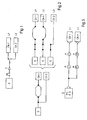
- the figure 2 illustrates the decomposition of a simple network into several lines. Each line has a source and a load. We can thus first of all consider the source S and the load Ch1. Note that two separate electrical paths connect the source S to the load Ch1. So we have to consider two power lines that are called, on the right of the figure 2 , L1 and L2. Considering then the source S and the load Ch2, we note that a single electrical path connects these two elements. This path thus forms the line called L3.
- the cable gauge must be compatible with the circuit breaker rating to protect the line before it is flowing through a current that causes it to overheat to a critical temperature. It is also necessary, in order to allow a good operation of the equipment, to limit voltage drops in line ( ⁇ Vmax). These voltage drops are determined beforehand according to the equipment supplied by the source.
- the insulators used for the cables do not all withstand the same temperatures.
- the choice of insulation will be mainly conditioned by the thermal constraints.
- the material conductor (aluminum or copper) in an aircraft depends on the area of the aircraft to which the cable is intended. Indeed, to avoid possible contamination, the use of aluminum cables is limited to certain areas of the aircraft.
- Specific constraints for example use of a shielded three-wire cable
- the type of cables to be used It is also necessary to take into account the admissible radius of curvature by the cable during its use. This prohibits the use of certain types of cables in confined spaces.
- the type of cable chosen must also take into account the connector to which it must be connected.
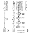
- the figure 5 illustrates the choice of cable gages on a line by taking over the source S and the load Ch of the figure 4 .
- C1, C2, C3 and C4 These cables measure respectively 2m, 18m, 30m and 10m.
- EL total length
- each cable C1 to C4 has been shown to show the various gauges that are a priori acceptable. These gauges are classified by their increasing mass indicated by the arrow on the left of the figure.
- the preferred combination retained here is a # 8 gauge cable C1, a # 4 gauge cable C2, a # 6 gauge cable C3 and a # 4 gauge cable C4.
- This combination gives a maximum voltage drop ⁇ V of 3.84V for a mass of 10.44kg. It is thus noted that the difference in cable mass between this preferential combination and the calculation of the cable gages of the prior art is 22%.
- the Figures 6 to 8 illustrate this optimized determination of the cable gages.
- the type t of the cables is represented on the abscissa and the gauge # on the ordinate.
- the gauge # on the ordinate.
- it represents all types and cable gauges that may be suitable when taking into account only the constraints concerning the current to flow in the cable, the environment in which the cable is (copper or aluminum), the thermal stresses, and also the constraints on connection. We then obtain a large number of possibilities. In the example of the figure 5 , they correspond to all the cable gages indicated. Once these valid cables have been selected, it must be verified that in terms of voltage drop the specifications are respected. The choice of cables is then limited as illustrated by figure 7 . Finally, when optimizing the mass of the cables, only a few cables can be retained, as shown on the diagram. figure 8 .
- the problem of mass optimization is a problem of discrete optimization (gauges / types of cables) under stress (voltage drop in line).
- the difficulty of such a problem increases considerably when the optimization is no longer on a line but on a network.
- Such a network can be schematized for example as on the figure 3 .
- a source S associated with a circuit breaker is connected to several charges Ch1 to Chn thus forming a set of lines L1 to Ln.
- the figure 9 shows in schematic form a calculation algorithm to obtain an optimization of the gauges and types of cables in a network.
- This database D symbolizes the various information available concerning the architecture of the aircraft. They are not necessarily grouped in the same physical database. It may even be assumed that some of the information required for the calculation explained below is not available in digital form but must be entered.
- the function F1 makes it possible to constitute the lines. From a switched network such as that of the figure 1 This F1 function automatically selects the different states of the switching components and thus searches for all the components making it possible to constitute a power line.
- the function F2 calculates, for each component of the line, the maximum currents Imax, in particular to size the cables in temperature and calculate the size of the circuit breaker.
- Function F3 calculates / checks the rating of the circuit breaker. If circuit breaker technology has not been specified, at this function F3 the circuit breaker with the minimum ohmic resistance is selected. It is already possible to calculate here the cable gauges compatible with the circuit breaker rating.
- the function F4 calculates the most constraining environment to which a predetermined cable is subjected.
- Business rules defined by a standard, require a choice of cable types and gauges depending on the airplane environment in which the cable travels. The same cable can cross aircraft zones of different characteristics (pressurized zone or not, different ambient temperature, etc ). Here we also obtain a set of compatible types / cable gages.
- the function F5 makes it possible to calculate the thermal stresses. This calculation is already done in the state of the art. Depending on the input data, different methods can be used. It is simply recalled here that the thermal stresses depend essentially on the maximum ambient temperature, the intensity of current flowing through the cable and also on its position in the aircraft.
- Function F6 calculates the connection constraints.
- the user of the system implementing the algorithm of the figure 9 has access for example to a table listing the connection elements that can be used. Based on these selected elements, the F6 function calculates the cable types / gauges compatible.
- the level of this function F6 a graphical interface allowing the user to visualize the elements of connections selected.
- Fibers are subsequently calculated (function F7) for the dimensioning of the cables under the stress ⁇ Vmax.
- the cable is then no longer considered here in isolation but as an element of the line Li in which it is integrated and where it contributes to a voltage drop ⁇ Vi.
- the value Idim i corresponds to the intensity of the current causing the maximum voltage drop ⁇ Vi.
- the function F8 makes it possible to calculate the maximum voltage drop allowed in the cables while also considering the intermediate voltage drops due to the presence of components (circuit-breaker, diode, etc.).
- the function F9 determines, before optimization, the valid types / cable gauges. According to the set of previously defined constraints, the function F9 calculates the valid solutions (types / gauges) for each of the cables of the network. It is verified here that for each of the cables of a line, the maximum voltage drop stress ( ⁇ Vmax) is not exceeded. In this way, we reduce the set of input solutions of the optimization algorithm.
- function F10 is the function for optimizing cable types / gauges.
- the functions F1 to F8 make it possible to determine the set of acceptable pairs / gages of the figure 6 .
- the function F9 makes it possible to switch to the type / gauge pairs represented on the figure 7 .
- the optimization function F10 makes it possible to retain only the types and gauges of the figure 8 .
- the goal of the optimization problem is to minimize the mass of the network.
- a second constraint is related to the Imax value.
- the maximum gauge is restricted by the corresponding circuit breaker rating as well as the Joule heating stress of the cable.
- this restriction is not the same depending on the material used for the cable. Since the material is related to the type of cable, the two variables are used here in this constraint.
- all sections are not available and there may also exist another constraint due to the connections. For each cable, it can therefore be said that its section (corresponding to its gauge) is greater (or equal) than a minimum section depending on the type of cable and the connectors and lower (or equal) to a maximum cross-sectional area of the circuit breaker, of the heating, the type of cable and the connections.
- a personal computer can be used for the implementation of this method. Programming on a conventional spreadsheet software can even be considered.
- the optimization of gauges and cable types is performed considering all segments of a functional link and not just a single link between two devices.
- the method described above makes it possible to dimension the cables automatically.
- this dimensioning is a complex exercise that requires a deep professional practice of the design profession.
- cumbersome and cumbersome calculations are required to resize the cables.
- Such a problem is frequently encountered during the development of a new aircraft.
- the definition of electrical harnesses is brought to evolve very regularly during the design of this new aircraft.
- the automatic calculation proposed by the invention makes it possible to quickly measure the effects of a routing evolution or a change of technology on the cable gages and to validate also that all the constraints are respected.
Abstract
Description
La présente invention concerne un procédé d'optimisation d'un câblage électrique, notamment dans le domaine aéronautique.The present invention relates to a method for optimizing electrical wiring, particularly in the aeronautical field.
Dans les aéronefs, le nombre de systèmes embarqués augmente continuellement dans le temps. Cette augmentation vise à obtenir des avions plus sûrs et plus performants. Elle conduit cependant à faire croître le nombre de câbles présents dans un aéronef. Ceci implique une masse de câbles électriques embarquée à bord d'un avion en constante progression dans le temps.In aircraft, the number of embedded systems increases continuously over time. This increase aims to obtain safer and more efficient aircraft. However, it leads to increasing the number of cables present in an aircraft. This implies a mass of electrical cables onboard a plane in constant progress over time.
Cette masse supplémentaire embarquée est pénalisante pour un aéronef donné. Lorsque la masse à vide augmente, il faut prévoir soit une motorisation plus puissante, soit une charge utile diminuée. Dans tous les cas de figure, la consommation en carburant de l'aéronef ramenée au passager transporté ou à la tonne de fret, augmente, impliquant de ce fait une hausse des coûts d'exploitation de l'aéronef.This additional mass onboard is penalizing for a given aircraft. When the empty weight increases, it is necessary to provide either a more powerful engine or a reduced payload. In all cases, the fuel consumption of the aircraft reduced to the passenger carried or the ton of freight, increases, thereby implying an increase in the operating costs of the aircraft.
Document
La présente invention a alors pour but de fournir des moyens permettant, pour un aéronef donné, de limiter la masse des câbles électriques nécessaire au câblage des divers systèmes de l'aéronef sans toutefois limiter leur nombre et/ou leur emplacement.The purpose of the present invention is therefore to provide means making it possible, for a given aircraft, to limit the mass of electrical cables necessary for wiring the various systems of the aircraft without, however, limiting their number and / or their location.
A cet effet, elle propose un procédé d'optimisation d'un câblage dans lequel les caractéristiques des câbles utilisés pour relier une source à une charge réceptrice sont définies en fonction de contraintes prédéterminées et environnementales.For this purpose, it proposes a method of optimizing a wiring in which the characteristics of the cables used to connect a source to a receiving load are defined according to predetermined and environmental constraints.
Selon l'invention, dans les cas où une ligne réalisant la liaison entre la source et la charge réceptrice comporte plusieurs câbles distincts reliés par des prises de coupure, la section des câbles est dimensionnée pour chaque câble de la ligne indépendamment des autres câbles puis optimisée en tenant compte des contraintes globales de la ligne.According to the invention, in the case where a line making the connection between the source and the receiving load comprises several separate cables connected by jacks, the section of the cables is dimensioned for each cable of the line independently of the other cables and optimized taking into account the global constraints of the line.
De manière originale, l'invention propose ici de non pas considérer une ligne reliant une source de puissance à un équipement récepteur comme une ligne de section constante mais comme une ligne de section variable. De cette manière, il est possible de limiter sur certaines portions de la ligne la section des câbles utilisés alors qu'il n'est pas possible d'avoir une section réduite sur la totalité de la ligne.In an original way, the invention proposes here not to consider a line connecting a power source to a receiving equipment as a line of constant section but as a line of variable section. In this way, it is possible to limit the section of the cables used on certain portions of the line when it is not possible to have a reduced section over the entire line.
Pour pouvoir déterminer au mieux la section des câbles utilisés, l'invention propose dans un mode de réalisation préféré que préalablement à la détermination de la section des câbles utilisés, le routage des lignes et câbles permettant de calculer un chemin à emprunter par les diverses lignes et câbles est effectué. Ainsi la connaissance du chemin que prennent les câbles permet une meilleure optimisation de la ligne car il est alors possible de déterminer le type de câble utilisé (blindé ou non, résistant à telle ou telle température, etc. ). Dans le cas d'un routage préalable, ce routage des lignes et câbles permet de préférence de déterminer la position au moins approximative des prises de coupure séparant deux câbles voisins. De cette manière, la longueur de chaque câble est connue et la masse des câbles peut être mieux déterminée.In order to be able to better determine the section of the cables used, the invention proposes in a preferred embodiment that prior to the determining the section of the cables used, the routing of lines and cables for calculating a path to be taken by the various lines and cables is performed. Thus the knowledge of the path taken by the cables allows a better optimization of the line because it is then possible to determine the type of cable used (shielded or not, resistant to such or such temperature, etc.). In the case of pre-routing, this routing of the lines and cables preferably makes it possible to determine the at least approximate position of the jacks separating two adjacent cables. In this way, the length of each cable is known and the mass of the cables can be better determined.
Dans une forme de réalisation d'un procédé d'optimisation selon l'invention, pour au moins un câble d'une ligne, plusieurs sections de câbles utilisables en fonction des contraintes imposées à ce câble sont déterminées ; ces câbles sont combinés selon diverses combinaisons pour former une ligne ; il est vérifié pour chaque ligne si les contraintes globales de la ligne sont satisfaites, et la ligne répondant aux contraintes techniques globales et de plus faible masse est sélectionnée.In one embodiment of an optimization method according to the invention, for at least one cable of a line, several cable sections that can be used according to the constraints imposed on this cable are determined; these cables are combined in various combinations to form a line; it is checked for each line if the global constraints of the line are satisfied, and the line answering the global and lower mass technical constraints is selected.
Toutes les caractéristiques des diverses variétés de câbles pouvant être utilisées pour réaliser le câblage considéré sont avantageusement mémorisées dans une base de données. Le terme variété est utilisé ici pour se distinguer du "type" de câble décrit plus loin. Le type d'un câble donne sa structure générale (dans le domaine électrique, il y a par exemple les câbles blindés ou non, avec un ou plusieurs fils, avec un isolant de telle ou telle nature, etc. ). La variété concerne ici aussi la section du câble. Ainsi deux câbles de même variété présentent à la fois une même section et sont d'un même type.All the characteristics of the various varieties of cables that can be used to make the wiring considered are advantageously stored in a database. The term variety is used here to distinguish itself from the "type" of cable described below. The type of cable gives its general structure (in the electrical field, there are for example shielded or unshielded cables, with one or more wires, with an insulator of such or such nature, etc.). The variety here also concerns the section of the cable. Thus two cables of the same variety have both the same section and are of the same type.
L'optimisation de la masse globale des câbles est réalisée de préférence sur deux variables discrètes, le type et la section des câbles.The optimization of the overall mass of the cables is preferably performed on two discrete variables, the type and section of the cables.
La présente invention est particulièrement adaptée pour être appliquée à la réalisation d'un câblage électrique. Dans ce cas, les contraintes prédéterminées comprennent par exemple une valeur d'intensité maximale définie par entre autres la consommation d'une charge et une chute de tension maximale admise. Dans ce domaine électrique, les contraintes environnementales comprennent par exemple la température environnante.The present invention is particularly adapted to be applied to the realization of electrical wiring. In this case, the predetermined constraints comprise for example a maximum intensity value defined by among others the consumption of a load and a maximum allowed voltage drop. In this electrical field, the environmental constraints include, for example, the surrounding temperature.
L'invention concerne également :
- un programme d'ordinateur stocké sur un support d'informations, ledit programme comportant des instructions permettant la mise en oeuvre d'un procédé d'optimisation tel que décrit ci-dessus, lorsque ce programme est chargé et exécuté par un système informatique, et
- un support d'informations lisible par un système informatique, éventuellement totalement ou partiellement amovible, notamment CD-ROM, DVD-ROM ou support magnétique, tel un disque dur ou une disquette, ou support transmissible, tel un signal électrique ou optique, caractérisé en ce qu'il comporte des instructions d'un programme d'ordinateur permettant la mise en oeuvre d'un procédé tel que décrit ci-dessus, lorsque ce programme est chargé et exécuté par un système informatique.
- a computer program stored on an information carrier, said program comprising instructions for implementing an optimization method as described above, when this program is loaded and executed by a computer system, and
- an information medium readable by a computer system, possibly totally or partially removable, in particular a CD-ROM, a DVD-ROM or a magnetic medium, such as a hard disk or a diskette, or a transmissible medium, such as an electrical or optical signal, characterized in it comprises instructions of a computer program for carrying out a method as described above, when this program is loaded and executed by a computer system.
Des détails et avantages de la présente invention ressortiront mieux de la description qui suit, faite en référence au dessin schématique annexé sur lequel :
- La
figure 1 représente schématiquement un circuit de type commuté, - La
figure 2 illustre la décomposition d'un réseau électrique en lignes, - La
figure 3 montre une représentation simplifiée d'un réseau, tel par exemple celui de lafigure 2 , après routage, - La
figure 4 illustre le choix du type et de la jauge de câbles dans l'état de l'art antérieur à la présente invention, - La
figure 5 illustre le choix du type et de la jauge de câbles dans l'exemple représenté sur lafigure 4 en utilisant un procédé selon l'invention, - Les
figures 6 à 8 illustrent schématiquement trois étapes d'un procédé selon l'invention, et - La
figure 9 est un organigramme correspondant à un algorithme pour la mise en oeuvre d'un procédé selon l'invention.
- The
figure 1 schematically represents a switched type circuit, - The
figure 2 illustrates the decomposition of an electrical network into lines, - The
figure 3 shows a simplified representation of a network, such as that of thefigure 2 , after routing, - The
figure 4 illustrates the choice of type and gauge of cables in the state of the art prior to the present invention, - The
figure 5 illustrates the choice of type and gauge of cables in the example shown on thefigure 4 using a method according to the invention, - The
Figures 6 to 8 schematically illustrate three steps of a method according to the invention, and - The
figure 9 is a flowchart corresponding to an algorithm for implementing a method according to the invention.
Le dessin illustre l'utilisation d'un procédé selon l'invention pour la réalisation d'un câblage électrique d'un aéronef. Un procédé semblable peut être utilisé dans des applications autres que l'aéronautique.The drawing illustrates the use of a method according to the invention for producing an electrical wiring of an aircraft. A similar process can be used in applications other than aeronautics.
La description ci-après montre comment, selon l'invention, il est possible de diminuer la masse globale des câbles d'un réseau électrique. Dans les aéronefs, l'augmentation du nombre de systèmes embarqués ainsi que l'augmentation des puissances consommées par les équipements de l'aéronef conduit à une augmentation de la masse des installations électriques de l'aéronef. Pour limiter cette augmentation, l'invention propose d'optimiser la masse des câbles reliant les divers systèmes embarqués et alimentant les équipements.The following description shows how, according to the invention, it is possible to reduce the overall weight of the cables of an electrical network. In aircraft, the increase in the number of onboard systems as well as the increase in the power consumed by the equipment of the aircraft leads to an increase in the mass of electrical installations of the aircraft. To limit this increase, the invention proposes to optimize the mass of cables connecting the various embedded systems and power equipment.
Bien entendu, le réseau électrique optimisé obtenu doit satisfaire à toutes les normes de sécurité sans agir sur les puissances consommées, ni sur le nombre des systèmes embarqués, ni même sur leur emplacement.Of course, the optimized electrical network obtained must meet all safety standards without affecting the power consumed, the number of embedded systems, or even their location.
Dans l'état de l'art antérieur à la présente invention (
Il convient maintenant de déterminer le type et la jauge du câble C1. Le type d'un câble électrique est codifié. L'indication du type d'un câble permet de connaître notamment le nombre de conducteurs constituant le câble, le matériau utilisé pour la réalisation des conducteurs, la nature de l'isolant ainsi que la présence éventuellement ainsi que la nature, d'un blindage. La jauge d'un câble, symbolisée par le signe # est exprimée suivant la norme AWG (American Wire Gauge). La valeur de la jauge diminue lorsque la section du conducteur, et donc sa résistance ohmique, augmente.The type and gauge of the C1 cable should now be determined. The type of an electric cable is codified. The indication of the type of a cable makes it possible to know in particular the number of conductors constituting the cable, the material used for producing the conductors, the nature of the insulation and the possible presence and nature of a shielding. . The gauge of a cable, symbolized by the # sign, is expressed according to the AWG (American Wire Gauge) standard. The value of the gauge decreases when the driver section, and therefore its ohmic resistance, increases.
Dans le cas présent illustré sur la
Par la suite, une fois tous les éléments étant définis (source, câble, équipement) des harnais électriques sont définis. Des électriciens définissent alors le chemin théorique de la liaison fonctionnelle reliant les divers équipements de l'aéronef. En fonction du chemin retenu, le type de câbles au niveau de chaque harnais est déterminé. En fonction des contraintes environnementales (température par exemple), des spécifications du schéma fonctionnel, des connecteurs prévus, etc..., le type de câbles est déterminé. Enfin, un contrôle final manuel permet de garantir que les définitions choisies correspondent bien aux spécifications requises.Subsequently, once all the elements are defined (source, cable, equipment) electrical harnesses are defined. Electricians then define the theoretical path of the functional link connecting the various equipment of the aircraft. Depending on the path chosen, the type of cable at each harness is determined. Depending on the environmental constraints (temperature for example), specifications of the block diagram, the connectors provided, etc., the cable type is determined. Finally, a manual final check ensures that the definitions chosen correspond to the required specifications.
La présente invention propose une manière nouvelle et originale de définir un réseau électrique, comme décrit ci-après.The present invention proposes a new and original way of defining an electrical network, as described below.
Tout d'abord, comme précédemment, l'architecture du système est créée. Des données relatives aux signaux (tension, courant, ...) ainsi que des exigences spécifiques auxquelles doit répondre le circuit (chutes maximales de tension, contraintes thermiques particulières, ...) sont définies.First, as before, the system architecture is created. Data relating to the signals (voltage, current, ...) as well as specific requirements to be met by the circuit (maximum voltage drops, special thermal stresses, etc.) are defined.
Dans un second temps, la position des équipements étant définie, on constitue les harnais électriques en déterminant notamment leur longueur. On peut alors réaliser le routage des liaisons fonctionnelles. On ne peut parler ici encore d'un routage physique étant donné que les jauges et les types de câbles ne sont pas encore déterminés. On connaît toutefois les chemins que peuvent prendre les divers câbles. Il s'agit alors de calculer la longueur de chacun d'eux à partir des données disponibles. Ces données sont de préférence rassemblées dans une base de données numérique qui constitue une "maquette" tridimensionnelle numérique de l'avion.In a second step, the position of the equipment being defined, it constitutes the electrical harnesses by determining in particular their length. It is then possible to carry out the routing of the functional links. Here again we can not talk about physical routing since the gauges and cable types are not yet determined. However, we know the paths that can take the various cables. It is then necessary to calculate the length of each one of them from the available data. These data are preferably collected in a digital database which constitutes a digital three-dimensional "model" of the aircraft.
Dans l'étape suivante les jauges et types des câbles sont calculés. L'ensemble des contraintes électriques, technologiques (matériau des câbles, connectique, ...) et thermiques est pris en compte pour s'assurer du bon et juste dimensionnement des câbles. On remarque qu'ici les jauges de câbles sont calculées après le routage de ceux-ci. La détermination des jauges des divers câbles est alors optimisée pour diminuer la masse globale du réseau de câbles. La présente invention concerne notamment cette dernière étape de détermination de la jauge des câbles et l'optimisation de celle-ci.In the next step the gauges and cable types are calculated. All the electrical, technological (cable material, connectors, ...) and thermal constraints are taken into account to ensure the correct and just dimensioning of the cables. Note that here the cable gauges are calculated after routing them. The determination of the gauges of the various cables is then optimized to reduce the overall mass of the cable network. The present invention relates in particular to this last step of determining the gauge of the cables and the optimization thereof.
Avant de détailler un exemple de détermination de la jauge de câbles selon l'invention, quelques définitions de mots utilisés par la suite sont données.Before detailing an example of determination of the cable gauge according to the invention, some definitions of words used subsequently are given.
Un réseau électrique est un ensemble de plusieurs sources reliées à plusieurs charges, ces sources et ces charges étant reliées par des câbles en mettant en oeuvre éventuellement des composants (disjoncteur, diode, ...).An electricity grid is a collection of several sources related to several loads, these sources and these loads being connected by cables possibly using components (circuit breaker, diode, etc.).
Une ligne est un sous-ensemble connexe d'un réseau faisant intervenir une seule source et une seule charge et comportant un ou plusieurs câbles ainsi qu'éventuellement un ou plusieurs composants. Une ligne est une combinaison unique de câbles et d'équipotentielles reliant la source à la charge.A line is a related subset of a single source, single load network with one or more cables and possibly one or more components. A line is a unique combination of cables and equipotentials connecting the source to the load.
La
Dans le cas d'un réseau commuté, comme illustré sur la
Pour déterminer les jauges de câbles, différentes contraintes doivent être prises en compte.To determine the cable gages, different constraints must be taken into account.
Il y a tout d'abord les contraintes électriques. La jauge de câble doit être compatible avec le calibre du disjoncteur afin de protéger la ligne avant que celle-ci ne soit parcourue par un courant l'amenant par échauffement à une température critique. Il convient également, afin de permettre un bon fonctionnement des équipements, de limiter les chutes de tension en ligne (ΔVmax). Ces chutes de tension sont déterminées préalablement en fonction des équipements alimentés par la source.First, there are electrical constraints. The cable gauge must be compatible with the circuit breaker rating to protect the line before it is flowing through a current that causes it to overheat to a critical temperature. It is also necessary, in order to allow a good operation of the equipment, to limit voltage drops in line (ΔVmax). These voltage drops are determined beforehand according to the equipment supplied by the source.
Il y a ensuite les contraintes thermiques. Pour empêcher tout risque d'échauffement excessif des câbles ou de vieillissement prématuré de l'installation électrique, il faut tenir compte notamment des dissipations par effet Joule, de la température ambiante ainsi que des conditions de refroidissement (air libre/confiné, etc ...).Then there are the thermal stresses. To prevent any risk of overheating of the cables or premature aging of the electrical system, Joule dissipation, ambient temperature and cooling conditions (free / confined air, etc.) must be taken into account. .).
Enfin, il y a les contraintes technologiques. Les isolants utilisés pour les câbles ne résistent pas tous aux mêmes températures. Le choix de l'isolant sera essentiellement conditionné par les contraintes thermiques. Le matériau conducteur (aluminium ou cuivre) dans un avion dépend de la zone de l'avion à laquelle le câble est destiné. En effet, pour éviter une contamination éventuelle, l'utilisation de câbles aluminium est limitée à certaines zones de l'avion. Des contraintes spécifiques (par exemple utilisation d'un câble trifilaire blindé) influent également le type de câbles à mettre en oeuvre. Il faut également tenir compte du rayon de courbure admissible par le câble lors de son utilisation. Ceci interdit l'utilisation de certains types de câbles dans des espaces confinés. Le type de câble choisi doit également tenir compte du connecteur auquel il doit être raccordé.Finally, there are the technological constraints. The insulators used for the cables do not all withstand the same temperatures. The choice of insulation will be mainly conditioned by the thermal constraints. The material conductor (aluminum or copper) in an aircraft depends on the area of the aircraft to which the cable is intended. Indeed, to avoid possible contamination, the use of aluminum cables is limited to certain areas of the aircraft. Specific constraints (for example use of a shielded three-wire cable) also affect the type of cables to be used. It is also necessary to take into account the admissible radius of curvature by the cable during its use. This prohibits the use of certain types of cables in confined spaces. The type of cable chosen must also take into account the connector to which it must be connected.
La
Les contraintes restent les mêmes que précédemment (
Sur la
Sur la droite de la figure sont indiquées des chutes de tension (ΔV) pour quatre exemples de combinaison de câbles. La première combinaison correspond à quatre câbles de jauge #8. Cette combinaison donne une chute de tension maximale ΔV de 6,89V. Cette solution n'est donc pas admissible, la chute de tension étant limitée à 4V. De même, si tous les câbles C1-C4 sont de jauge #6, la chute de tension ΔV est de 4,62V, ce qui n'est pas acceptable. Avec quatre câbles de jauge #4, on arrive à la solution de l'art antérieur illustré sur la
Les
Dans l'exemple de la
Compte tenu du nombre important de câbles présents dans un aéronef moderne, un calcul d'optimisation simultané sur tous les câbles semble difficilement réalisable car il demanderait des moyens de calcul trop importants. Toutefois, on peut distinguer dans un aéronef plusieurs réseaux plus ou moins indépendants les uns des autres. Une optimisation de la masse peut être réalisée réseau par réseau.Given the large number of cables present in a modern aircraft, a simultaneous optimization calculation on all cables seems difficult to achieve because it would require too much calculation means. However, one can distinguish in an aircraft several networks more or less independent of each other. An optimization of the mass can be carried out network by network.
La
Les différentes informations nécessaires pour définir le réseau électrique de l'aéronef sont regroupées dans une base de données D. Cette base de données D symbolise les diverses informations disponibles concernant l'architecture de l'aéronef. Elles ne sont pas forcément regroupées dans une même base de données physique. On peut même supposer que certaines de ces informations nécessaires au calcul exposé ci-après ne sont pas disponibles sous forme numérique mais doivent être saisies.The different information needed to define the network This database D symbolizes the various information available concerning the architecture of the aircraft. They are not necessarily grouped in the same physical database. It may even be assumed that some of the information required for the calculation explained below is not available in digital form but must be entered.
La fonction F1 permet de constituer les lignes. A partir d'un réseau commuté tel celui de la
La fonction F2 calcule, pour chaque composante de la ligne, les courants maximaux Imax, afin notamment de dimensionner les câbles en température et de calculer le calibre du disjoncteur.The function F2 calculates, for each component of the line, the maximum currents Imax, in particular to size the cables in temperature and calculate the size of the circuit breaker.
La fonction F3 calcule/vérifie le calibre du disjoncteur. Si la technologie du disjoncteur n'a pas été spécifiée, au niveau de cette fonction F3 le disjoncteur présentant la résistance ohmique minimale est sélectionné. On peut déjà calculer à ce niveau là les jauges de câbles compatibles avec le calibre du disjoncteur.Function F3 calculates / checks the rating of the circuit breaker. If circuit breaker technology has not been specified, at this function F3 the circuit breaker with the minimum ohmic resistance is selected. It is already possible to calculate here the cable gauges compatible with the circuit breaker rating.
A partir des données D, la fonction F4 calcule l'environnement le plus contraignant auquel est soumis un câble prédéterminé. Les règles métier, définies par une norme, imposent un choix de types et de jauges de câbles en fonction de l'environnement avion dans lequel ce câble chemine. Un même câble peut traverser des zones avion de caractéristiques différentes (zone pressurisée ou non, température ambiante différente, etc ...). On obtient ici aussi un ensemble de types/jauges de câbles compatibles.From the data D, the function F4 calculates the most constraining environment to which a predetermined cable is subjected. Business rules, defined by a standard, require a choice of cable types and gauges depending on the airplane environment in which the cable travels. The same cable can cross aircraft zones of different characteristics (pressurized zone or not, different ambient temperature, etc ...). Here we also obtain a set of compatible types / cable gages.
La fonction F5 permet de calculer les contraintes thermiques. Ce calcul est déjà réalisé dans l'état de l'art. Selon les données fournies en entrée, des méthodes différentes peuvent être utilisées. On rappelle ici simplement que les contraintes thermiques dépendent essentiellement de la température ambiante maximale, de l'intensité de courant traversant le câble et également de sa position dans l'aéronef.The function F5 makes it possible to calculate the thermal stresses. This calculation is already done in the state of the art. Depending on the input data, different methods can be used. It is simply recalled here that the thermal stresses depend essentially on the maximum ambient temperature, the intensity of current flowing through the cable and also on its position in the aircraft.
La fonction F6 calcule les contraintes de connectique. Ici, l'utilisateur du système mettant en oeuvre l'algorithme de la
Le résultat des calculs des fonctions F3, F4, F5 et F6 donnant un ensemble de types et de jauges valides est regroupé au niveau de la case de la
On calcule par la suite (fonction F7) des courants Idim permettant le dimensionnement des câbles sous la contrainte ΔVmax. Le câble n'est alors plus considéré ici isolément mais comme un élément de la ligne Li dans laquelle il est intégré et où il contribue à une chute de tension ΔVi. Ainsi, pour la ligne Li la valeur Idimi correspond à l'intensité du courant provoquant la chute de tension ΔVi maximale.Fibers are subsequently calculated (function F7) for the dimensioning of the cables under the stress ΔVmax. The cable is then no longer considered here in isolation but as an element of the line Li in which it is integrated and where it contributes to a voltage drop ΔVi. Thus, for the line Li, the value Idim i corresponds to the intensity of the current causing the maximum voltage drop ΔVi.
La fonction F8 permet de calculer la chute de tension maximale autorisée dans les câbles en considérant également les chutes de tension intermédiaires dues à la présence de composants (disjoncteur, diode, etc...).The function F8 makes it possible to calculate the maximum voltage drop allowed in the cables while also considering the intermediate voltage drops due to the presence of components (circuit-breaker, diode, etc.).
La fonction F9 détermine, avant optimisation, les types/jauges de câbles valides. En fonction de l'ensemble des contraintes préalablement définies, la fonction F9 calcule les solutions (types/jauges) valides pour chacun des câbles du réseau. On vérifie ici que pour chacun des câbles d'une ligne, la contrainte de chute de tension maximale (ΔVmax) n'est pas dépassée. De cette manière, on réduit l'ensemble des solutions en entrée de l'algorithme d'optimisation.The function F9 determines, before optimization, the valid types / cable gauges. According to the set of previously defined constraints, the function F9 calculates the valid solutions (types / gauges) for each of the cables of the network. It is verified here that for each of the cables of a line, the maximum voltage drop stress (ΔVmax) is not exceeded. In this way, we reduce the set of input solutions of the optimization algorithm.
Enfin, la fonction F10 est la fonction permettant l'optimisation des types/jauges de câbles. Schématiquement, les fonctions F1 à F8 permettent de déterminer l'ensemble des couples types/jauges admissibles de la
Le but du problème d'optimisation est de minimiser la masse du réseau. Mathématiquement, on peut formuler ceci en indiquant que la masse globale est la somme des masses de câbles. On sait que ces masses dépendent du type des câbles, de la jauge des câbles et de la longueur de ceux-ci. Comme pour une ligne donnée la longueur globale du câble est constante, l'optimisation se fait sur les deux variables discrètes qui sont les types et sections (ou jauges) des câbles.The goal of the optimization problem is to minimize the mass of the network. Mathematically, we can formulate this by indicating that the global mass is the sum of the masses of cables. It is known that these masses depend on the type of cables, the gauge of the cables and the length thereof. As for a given line the overall length of the cable is constant, the optimization is done on the two discrete variables which are the types and sections (or gauges) of the cables.
Cette somme doit être minimisée avec des contraintes.This sum must be minimized with constraints.
Comme première contrainte, on exprime que pour chaque câble d'une ligne, le type du câble est restreint par les zones avion traversées. On peut également exprimer dans cette contrainte le nombre de fils que chaque câble doit comporter.As a first constraint, it is expressed that for each cable of a line, the type of the cable is restricted by the crossed plane areas. It is also possible to express in this constraint the number of wires that each cable must contain.
Une seconde contrainte est liée à la valeur Imax. Pour chaque câble, la jauge maximale est restreinte par le calibre disjoncteur correspondant ainsi que par la contrainte d'échauffement par effet Joule du câble. Toutefois, cette restriction n'est pas la même suivant le matériau employé pour le câble. Le matériau étant lié au type de câble, on fait intervenir ici dans cette contrainte les deux variables. En outre, suivant les types de câbles employés, toutes les sections ne sont pas disponibles et il peut de plus exister une autre contrainte due à la connectique. Pour chaque câble, on peut donc indiquer que sa section (correspondant à sa jauge) est supérieure (ou égale) à une section minimale dépendant du type de câble et de la connectique et inférieure (ou égale) à une section maximale dépendant du disjoncteur, de l'échauffement, du type de câble et de la connectique.A second constraint is related to the Imax value. For each cable, the maximum gauge is restricted by the corresponding circuit breaker rating as well as the Joule heating stress of the cable. However, this restriction is not the same depending on the material used for the cable. Since the material is related to the type of cable, the two variables are used here in this constraint. In addition, depending on the type of cable used, all sections are not available and there may also exist another constraint due to the connections. For each cable, it can therefore be said that its section (corresponding to its gauge) is greater (or equal) than a minimum section depending on the type of cable and the connectors and lower (or equal) to a maximum cross-sectional area of the circuit breaker, of the heating, the type of cable and the connections.
Comme troisième contrainte, il convient de considérer les chutes de tension en lignes. Pour chaque ligne, on veut que la chute de tension sur l'ensemble des câbles ne dépasse pas une valeur maximale ΔVmax. Cette valeur maximale tient compte de la chute de tension sur l'ensemble de la ligne, câbles et composants compris. Il faut donc, dans une ligne donnée, que la somme des chutes de tension calculées reste inférieure à la valeur maximale ΔVmax admise.As a third constraint, voltage drops in lines should be considered. For each line, it is desired that the voltage drop across all the cables does not exceed a maximum value ΔVmax. This maximum value takes into account the voltage drop across the entire line, including cables and components. It is therefore necessary, in a given line, that the sum of the calculated voltage drops remains lower than the maximum value ΔVmax allowed.
Mathématiquement, il convient donc de minimiser la fonction sur les masses en tenant compte des trois contraintes précitées. La mise en équation de ce problème se déduit immédiatement de ce qui précède. La résolution du système d'équations ainsi posé est un problème classique auquel l'homme du métier sait normalement faire face.Mathematically, it is therefore necessary to minimize the function on the masses taking into account the three aforementioned constraints. The equation of this problem is deduced immediately from the above. The resolution of the system of equations thus posed is a classic problem which the skilled person normally knows how to cope with.
Pour ce problème précis, on peut donner quelques indications sur un algorithme de résolution. Ainsi par exemple, au lieu d'utiliser comme variable discrète les jauges de câbles, on peut assimiler celles-ci à des fonctions continues telle la résistance et/ou la masse linéique en fonction de la section du câble. Cet artifice permet d'utiliser les méthodes et les algorithmes classiques d'optimisation basés sur la dérivation de fonctions.For this specific problem, we can give some indications on a resolution algorithm. For example, instead of using the cable gages as a discrete variable, these can be likened to continuous functions such as the resistance and / or the linear density as a function of the section of the cable. This artifice makes it possible to use conventional optimization methods and algorithms based on the derivation of functions.
Cependant, si rendre la section du câble continue correspond à une réalité physique, il n'en est pas de même pour le type du câble. Afin d'augmenter les chances de converger vers un minimum global, l'algorithme de résolution est lancé plusieurs fois avec des points initiaux différents. On estime qu'un tel procédé permet de trouver une solution dégradée au maximum de 10% par rapport à la solution optimale.However, if making the section of the cable continues corresponds to a physical reality, it is not the same for the type of cable. In order to increase the chances of converging to a global minimum, the resolution algorithm is run multiple times with different initial points. It is estimated that such a method makes it possible to find a degraded solution at most 10% with respect to the optimal solution.
La procédure la plus adaptée de l'algorithmique traditionnelle des mathématiques est celle dite de séparation et d'évaluation (connue sous le nom anglais Branch & Bound). Celle-ci permet d'identifier le minimum global des solutions mais le temps de résolution évolue exponentiellement en fonction de la taille du problème dont le volume devient rapidement important. L'optimisation continue suggérée précédemment permet ici de faciliter la recherche de solutions.The most adapted procedure of the traditional algorithmic of mathematics is that known as separation and evaluation (known under the English name Branch & Bound). This allows to identify the global minimum of the solutions but the resolution time evolves exponentially according to the size of the problem whose volume quickly becomes important. The continuous optimization suggested above allows here to facilitate the search for solutions.
La mise en oeuvre du procédé décrit ci-dessus, comme prototype, a permis de réaliser des gains de masse sensibles. Ce procédé permet donc, sans nullement toucher à l'architecture définie préalablement d'un réseau électrique d'un aéronef, de diminuer sensiblement la masse des câbles mis en oeuvre tout en respectant les mêmes contraintes que dans l'art antérieur (contraintes électriques, thermiques, connectique, etc ...).The implementation of the method described above, as a prototype, made it possible to achieve significant mass gains. This method therefore makes it possible, without in any way affecting the previously defined architecture of an electrical network of an aircraft, to substantially reduce the mass of the cables used while respecting the same constraints as in the prior art (electrical stresses, thermal, connectivity, etc ...).
Un ordinateur personnel peut être utilisé pour la mise en oeuvre de ce procédé. Une programmation sur un logiciel tableur classique peut même être envisagée.A personal computer can be used for the implementation of this method. Programming on a conventional spreadsheet software can even be considered.
L'optimisation des jauges et types de câbles est réalisée en considérant tous les segments d'une liaison fonctionnelle et non pas uniquement une liaison unique entre deux équipements. Le procédé décrit ci-dessus permet de dimensionner automatiquement les câbles. Actuellement, ce dimensionnement est un exercice complexe qui nécessite une pratique professionnelle profonde du métier de conception. Lorsque les longueurs de câbles évoluent, des calculs lourds et fastidieux sont nécessaires pour redimensionner les câbles. Un tel problème est fréquemment rencontré au cours du développement d'un nouvel aéronef. En effet, la définition des harnais électriques est amenée à évoluer très régulièrement durant la conception de ce nouvel aéronef. Le calcul automatique proposé par l'invention permet de mesurer rapidement les effets d'une évolution de routage ou d'un changement de technologie sur les jauges de câbles et de valider également que toutes les contraintes sont respectées.The optimization of gauges and cable types is performed considering all segments of a functional link and not just a single link between two devices. The method described above makes it possible to dimension the cables automatically. Currently, this dimensioning is a complex exercise that requires a deep professional practice of the design profession. As cable lengths change, cumbersome and cumbersome calculations are required to resize the cables. Such a problem is frequently encountered during the development of a new aircraft. Indeed, the definition of electrical harnesses is brought to evolve very regularly during the design of this new aircraft. The automatic calculation proposed by the invention makes it possible to quickly measure the effects of a routing evolution or a change of technology on the cable gages and to validate also that all the constraints are respected.
La présente invention ne se limite pas à la forme de réalisation préférentielle décrite ci-dessus à titre d'exemple non limitatif. Elle concerne également toutes les variantes de réalisation à la portée de l'homme du métier dans le cadre des revendications ci-après.The present invention is not limited to the preferred embodiment described above by way of non-limiting example. It also relates to all the variants within the scope of those skilled in the art within the scope of the claims below.
Claims (11)
- Optimization method for cabling in which the characteristics of the cables used for connecting a source (S) to a receiving load (Ch) are defined on the basis of constraints that are predetermined and environmental,
characterized in that In the cases where a line (Li) making the connection between the source (S) and the receiving load (Ch) comprises several distinct cables (Ci) connected by cutout connectors (P), the cross-section of the cables is dimensioned for each cable (Ci) in the line, independently of the other cables, and is then optimized while taking the overall constraints of the line (Li) into account. - Optimization method in accordance with claim 1, characterized in that prior to the determination of the cross-section of the cables (Cl) used, the routing of the lines (Li) and cables (Ci) is carried out which makes it possible to calculate a path to be taken by the various lines and cables.
- Optimization method in accordance with claim 2, characterized in that the routing of the lines and cables makes it possible to determine at least approximately the position of the cutout connectors (P) that separate two neighboring cables (Ci).
- Optimization method in accordance with one of the claims 1 through 3, characterized in that for at least one cable (Ci) of a line, several usable cable cross-sections are determined on the basis of the constraints imposed upon said cable (Ci), in that said cables (Ci) are combined in different combinations in order to form a line, in that it is verified for each line whether the overall constraints for the line have been satisfied, and in that the line meeting the overall technical constraints and having the lowest mass is selected.
- Optimization method in accordance with one of the claims 1 through 4, characterized in that all of the characteristics of the different varieties of cables capable of being used for implementing the cabling under consideration are stored in a data base (D).
- Optimization method in accordance with one of the claims 1 through 5, characterized in that the optimization of the overall mass of the cables is implemented for two discrete variables, for the type and for the cross-section of the cables.
- Optimization method in accordance with one of the claims 1 through 6, characterized in that it is applied to the implementation of electrical cabling,
- Optimization method in accordance with claim 7, characterized in that the predetermined constraints comprise a maximum intensity value defined by a circuit breaker and a maximum permissible drop in voltage.
- Optimization method in accordance with one of the claims 7 or 8, characterized in that the environmental constraints comprise the ambient temperature.
- Computer program stored on a data storage medium, said program comprising instructions enabling the implementation of an optimization method in accordance with any one of the claims 1 through 9 when that program is loaded and executed by a data processing system.
- Data carrier that is readable by a data processing system, possibly entirely or partially removable, in particular a CD-ROM. DVD-ROM or a magnetic carrier, such as a hard disk or a floppy disk, or a transmittable carrier such as an electric signal or an optical signal, characterized in that it comprises instructions of a computer program enabling the implementation of a method in accordance with any one of the claims 1 through 9, when that program is loaded and executed by a data processing system.
Applications Claiming Priority (2)
| Application Number | Priority Date | Filing Date | Title |
|---|---|---|---|
| FR0403468A FR2868573B1 (en) | 2004-04-02 | 2004-04-02 | METHOD FOR OPTIMIZING AN ELECTRICAL WIRING, IN PARTICULAR IN THE AERONAUTICAL FIELD |
| FR0403468 | 2004-04-02 |
Publications (2)
| Publication Number | Publication Date |
|---|---|
| EP1583193A1 EP1583193A1 (en) | 2005-10-05 |
| EP1583193B1 true EP1583193B1 (en) | 2010-08-25 |
Family
ID=34878486
Family Applications (1)
| Application Number | Title | Priority Date | Filing Date |
|---|---|---|---|
| EP05290647A Not-in-force EP1583193B1 (en) | 2004-04-02 | 2005-03-24 | Optimization method of an electrical wiring, especially in the aeronautic field |
Country Status (6)
| Country | Link |
|---|---|
| US (1) | US7676771B2 (en) |
| EP (1) | EP1583193B1 (en) |
| AT (1) | ATE479220T1 (en) |
| CA (1) | CA2498732C (en) |
| DE (1) | DE602005023089D1 (en) |
| FR (1) | FR2868573B1 (en) |
Families Citing this family (8)
| Publication number | Priority date | Publication date | Assignee | Title |
|---|---|---|---|---|
| FR2900292B1 (en) * | 2006-04-21 | 2008-11-14 | Airbus France Sas | SECURITY DEVICE FOR SEMICONDUCTOR SWITCH |
| US20100052642A1 (en) * | 2008-08-26 | 2010-03-04 | Broadcom Corporation | System and method for using a phy's discovery of cable shielding for power over ethernet current capacity setting and temperature de-rating |
| FR2970579B1 (en) * | 2011-01-13 | 2013-01-11 | Peugeot Citroen Automobiles Sa | DEVICE AND METHOD FOR CALCULATING OPTIMUM SECTIONS OF STRINGS OF AT LEAST ONE ELECTRIC LINE BASED ON THE MAXIMUM VOLTAGE DROP AUTHORIZED ON THIS LINE |
| FR3012661B1 (en) * | 2013-10-28 | 2015-12-04 | Labinal | METHOD FOR CHARACTERIZING A TORON OF ELECTRIC CABLES |
| CN107370146B (en) * | 2017-06-06 | 2020-07-17 | 国网江西省电力公司萍乡供电分公司 | Linear tower power transmission line windage yaw discharge probability online early warning method considering wind randomness influence |
| CN111046488B (en) * | 2019-11-25 | 2023-07-25 | 北京空间技术研制试验中心 | Three-dimensional wiring method for spacecraft cable |
| CN114237076B (en) * | 2021-12-17 | 2023-12-12 | 北京理工大学 | Method and controller for motion simulation of movable cable based on position dynamics |
| CN114615149B (en) * | 2022-05-12 | 2022-08-02 | 南昌航空大学 | Optimization method for data interaction network structure of multi-power system of aircraft |
Family Cites Families (9)
| Publication number | Priority date | Publication date | Assignee | Title |
|---|---|---|---|---|
| JPH11272727A (en) * | 1998-03-23 | 1999-10-08 | Hitachi Plant Eng & Constr Co Ltd | Wiring route design support method |
| FR2791475B1 (en) * | 1999-03-23 | 2007-02-23 | Sagem | RADIANT CABLE |
| DE19935422A1 (en) * | 1999-07-28 | 2001-02-01 | Daimler Chrysler Ag | Generation of electrical line structure with cable bundles, using design for mechanical construction portrayed by data-processing installation and adding on connection plan of electrical system |
| WO2001024111A1 (en) * | 1999-09-30 | 2001-04-05 | Routech, Inc. | Automatic routing system for pc board design |
| US6664656B2 (en) * | 2000-09-14 | 2003-12-16 | The Boeing Company | Aircraft electrical power distribution network |
| US6886152B1 (en) * | 2002-08-09 | 2005-04-26 | Xilinx, Inc. | Delay optimization in signal routing |
| US7194720B1 (en) * | 2003-07-11 | 2007-03-20 | Altera Corporation | Method and apparatus for implementing soft constraints in tools used for designing systems on programmable logic devices |
| US7057734B2 (en) * | 2003-07-23 | 2006-06-06 | Honeywell International Inc. | Integrated reaction wheel assembly and fiber optic gyro |
| US7100142B2 (en) * | 2004-04-07 | 2006-08-29 | Synopsys, Inc. | Method and apparatus for creating a mask-programmable architecture from standard cells |
-
2004
- 2004-04-02 FR FR0403468A patent/FR2868573B1/en not_active Expired - Fee Related
-
2005
- 2005-03-01 CA CA2498732A patent/CA2498732C/en not_active Expired - Fee Related
- 2005-03-24 EP EP05290647A patent/EP1583193B1/en not_active Not-in-force
- 2005-03-24 AT AT05290647T patent/ATE479220T1/en not_active IP Right Cessation
- 2005-03-24 DE DE602005023089T patent/DE602005023089D1/en active Active
- 2005-04-04 US US11/097,276 patent/US7676771B2/en not_active Expired - Fee Related
Also Published As
| Publication number | Publication date |
|---|---|
| DE602005023089D1 (en) | 2010-10-07 |
| FR2868573B1 (en) | 2006-06-23 |
| CA2498732A1 (en) | 2005-10-02 |
| EP1583193A1 (en) | 2005-10-05 |
| US20050271350A1 (en) | 2005-12-08 |
| ATE479220T1 (en) | 2010-09-15 |
| FR2868573A1 (en) | 2005-10-07 |
| CA2498732C (en) | 2015-06-16 |
| US7676771B2 (en) | 2010-03-09 |
Similar Documents
| Publication | Publication Date | Title |
|---|---|---|
| EP1583193B1 (en) | Optimization method of an electrical wiring, especially in the aeronautic field | |
| CA2576916C (en) | Method and device for detecting electric arc phenomenon on at least one electric cable | |
| CA2911222C (en) | Protective sheath for an electrical harness in order to prevent the deterioration of same | |
| EP3406014B1 (en) | System and method for dynamically determining maximum electric current carrying capacities | |
| EP2629998B1 (en) | Device and method for estimating a touch current and protecting an electrical apparatus against such touch currents | |
| FR3052364A1 (en) | ELECTRICAL POWER SUPPLY SYSTEM OF A CAPTIVE TELEOPERED APPARATUS | |
| CA2927711C (en) | Method for characterising a strand of electric cables | |
| FR2983175A1 (en) | WIRING OF A PANEL OF AIRCRAFT BREAKERS | |
| CA2346313C (en) | Electric energy transmission and distribution system | |
| FR2997508A1 (en) | Longitudinal cable for transport of data or electric energy in harness of aircraft, has elementary areas having sensor elements, where each sensor element performs measurement of health parameter of cable in respective elementary area | |
| EP3590121B1 (en) | Redundant and dissimilar system for monitoring the status of control contactors of an aircraft control stick | |
| EP2342793B1 (en) | Electric network architecture for confined environments including electric power sources | |
| FR2982053B1 (en) | DEVICE AND METHOD FOR DIMENSIONING ELECTRIC CABLES WITH INTERNAL TEMPERATURE CALCULATION USING NODAL CELL DECOMPOSITION AND MATRIX FUSION. | |
| FR3063839B1 (en) | LIGHTNING PROTECTION SYSTEM FOR AN AIRCRAFT | |
| FR3085154A1 (en) | METHOD FOR MAINTAINING AN ELECTRICAL DISTRIBUTION SYSTEM | |
| WO2020039143A1 (en) | Method for self-configuration of an autonomous electronic board of static circuit breakers | |
| EP0964256A1 (en) | Method and device for locating short circuits in a bus of a multiplexed network for information transmission | |
| EP2912480A1 (en) | System and method for monitoring a meshed current return network of an aircraft | |
| WO2023170368A1 (en) | Detecting an electric arc by means of a bragg grating | |
| FR3076670A1 (en) | POWER SUPPLY NETWORK AND METHOD OF CONTROLLING THE SAME | |
| FR3073099A1 (en) | ELECTRICAL DISTRIBUTION AND DATA CONCENTRATION BOX FOR AIRCRAFT. | |
| Lu | Analysis of the coupling effects on main feeder in more electrical aircraft | |
| FR3080201A1 (en) | METHOD AND SYSTEM OF PROCESSING FOR THE GENERATION OF A SCHEMATIC REPRESENTATION OF A TARGET ELECTRIC ARCHITECTURE | |
| EP2987101A1 (en) | Device and method for dimensioning electrical cables, with calculation of the internal temperature by cell node breakdown and matrix melting | |
| FR3010213A1 (en) | METHOD OF REDUCING THE DIVERSITY OF A STOCK OF ELECTRICAL BEAMS |
Legal Events
| Date | Code | Title | Description |
|---|---|---|---|
| PUAI | Public reference made under article 153(3) epc to a published international application that has entered the european phase |
Free format text: ORIGINAL CODE: 0009012 |
|
| AK | Designated contracting states |
Kind code of ref document: A1 Designated state(s): AT BE BG CH CY CZ DE DK EE ES FI FR GB GR HU IE IS IT LI LT LU MC NL PL PT RO SE SI SK TR |
|
| AX | Request for extension of the european patent |
Extension state: AL BA HR LV MK YU |
|
| 17P | Request for examination filed |
Effective date: 20060330 |
|
| AKX | Designation fees paid |
Designated state(s): AT BE BG CH CY CZ DE DK EE ES FI FR GB GR HU IE IS IT LI LT LU MC NL PL PT RO SE SI SK TR |
|
| GRAP | Despatch of communication of intention to grant a patent |
Free format text: ORIGINAL CODE: EPIDOSNIGR1 |
|
| GRAS | Grant fee paid |
Free format text: ORIGINAL CODE: EPIDOSNIGR3 |
|
| GRAA | (expected) grant |
Free format text: ORIGINAL CODE: 0009210 |
|
| RAP1 | Party data changed (applicant data changed or rights of an application transferred) |
Owner name: AIRBUS OPERATIONS |
|
| AK | Designated contracting states |
Kind code of ref document: B1 Designated state(s): AT BE BG CH CY CZ DE DK EE ES FI FR GB GR HU IE IS IT LI LT LU MC NL PL PT RO SE SI SK TR |
|
| REG | Reference to a national code |
Ref country code: GB Ref legal event code: FG4D Free format text: NOT ENGLISH |
|
| REG | Reference to a national code |
Ref country code: CH Ref legal event code: EP |
|
| REG | Reference to a national code |
Ref country code: IE Ref legal event code: FG4D Free format text: LANGUAGE OF EP DOCUMENT: FRENCH |
|
| REF | Corresponds to: |
Ref document number: 602005023089 Country of ref document: DE Date of ref document: 20101007 Kind code of ref document: P |
|
| REG | Reference to a national code |
Ref country code: NL Ref legal event code: VDEP Effective date: 20100825 |
|
| LTIE | Lt: invalidation of european patent or patent extension |
Effective date: 20100825 |
|
| PG25 | Lapsed in a contracting state [announced via postgrant information from national office to epo] |
Ref country code: AT Free format text: LAPSE BECAUSE OF FAILURE TO SUBMIT A TRANSLATION OF THE DESCRIPTION OR TO PAY THE FEE WITHIN THE PRESCRIBED TIME-LIMIT Effective date: 20100825 Ref country code: FI Free format text: LAPSE BECAUSE OF FAILURE TO SUBMIT A TRANSLATION OF THE DESCRIPTION OR TO PAY THE FEE WITHIN THE PRESCRIBED TIME-LIMIT Effective date: 20100825 Ref country code: LT Free format text: LAPSE BECAUSE OF FAILURE TO SUBMIT A TRANSLATION OF THE DESCRIPTION OR TO PAY THE FEE WITHIN THE PRESCRIBED TIME-LIMIT Effective date: 20100825 |
|
| PG25 | Lapsed in a contracting state [announced via postgrant information from national office to epo] |
Ref country code: IS Free format text: LAPSE BECAUSE OF FAILURE TO SUBMIT A TRANSLATION OF THE DESCRIPTION OR TO PAY THE FEE WITHIN THE PRESCRIBED TIME-LIMIT Effective date: 20101225 Ref country code: BG Free format text: LAPSE BECAUSE OF FAILURE TO SUBMIT A TRANSLATION OF THE DESCRIPTION OR TO PAY THE FEE WITHIN THE PRESCRIBED TIME-LIMIT Effective date: 20101125 Ref country code: CY Free format text: LAPSE BECAUSE OF FAILURE TO SUBMIT A TRANSLATION OF THE DESCRIPTION OR TO PAY THE FEE WITHIN THE PRESCRIBED TIME-LIMIT Effective date: 20100825 Ref country code: PL Free format text: LAPSE BECAUSE OF FAILURE TO SUBMIT A TRANSLATION OF THE DESCRIPTION OR TO PAY THE FEE WITHIN THE PRESCRIBED TIME-LIMIT Effective date: 20100825 Ref country code: PT Free format text: LAPSE BECAUSE OF FAILURE TO SUBMIT A TRANSLATION OF THE DESCRIPTION OR TO PAY THE FEE WITHIN THE PRESCRIBED TIME-LIMIT Effective date: 20101227 Ref country code: SI Free format text: LAPSE BECAUSE OF FAILURE TO SUBMIT A TRANSLATION OF THE DESCRIPTION OR TO PAY THE FEE WITHIN THE PRESCRIBED TIME-LIMIT Effective date: 20100825 |
|
| REG | Reference to a national code |
Ref country code: IE Ref legal event code: FD4D |
|
| PG25 | Lapsed in a contracting state [announced via postgrant information from national office to epo] |
Ref country code: GR Free format text: LAPSE BECAUSE OF FAILURE TO SUBMIT A TRANSLATION OF THE DESCRIPTION OR TO PAY THE FEE WITHIN THE PRESCRIBED TIME-LIMIT Effective date: 20101126 Ref country code: NL Free format text: LAPSE BECAUSE OF FAILURE TO SUBMIT A TRANSLATION OF THE DESCRIPTION OR TO PAY THE FEE WITHIN THE PRESCRIBED TIME-LIMIT Effective date: 20100825 Ref country code: SE Free format text: LAPSE BECAUSE OF FAILURE TO SUBMIT A TRANSLATION OF THE DESCRIPTION OR TO PAY THE FEE WITHIN THE PRESCRIBED TIME-LIMIT Effective date: 20100825 |
|
| PG25 | Lapsed in a contracting state [announced via postgrant information from national office to epo] |
Ref country code: DK Free format text: LAPSE BECAUSE OF FAILURE TO SUBMIT A TRANSLATION OF THE DESCRIPTION OR TO PAY THE FEE WITHIN THE PRESCRIBED TIME-LIMIT Effective date: 20100825 Ref country code: IE Free format text: LAPSE BECAUSE OF FAILURE TO SUBMIT A TRANSLATION OF THE DESCRIPTION OR TO PAY THE FEE WITHIN THE PRESCRIBED TIME-LIMIT Effective date: 20100825 |
|
| PG25 | Lapsed in a contracting state [announced via postgrant information from national office to epo] |
Ref country code: EE Free format text: LAPSE BECAUSE OF FAILURE TO SUBMIT A TRANSLATION OF THE DESCRIPTION OR TO PAY THE FEE WITHIN THE PRESCRIBED TIME-LIMIT Effective date: 20100825 Ref country code: SK Free format text: LAPSE BECAUSE OF FAILURE TO SUBMIT A TRANSLATION OF THE DESCRIPTION OR TO PAY THE FEE WITHIN THE PRESCRIBED TIME-LIMIT Effective date: 20100825 Ref country code: RO Free format text: LAPSE BECAUSE OF FAILURE TO SUBMIT A TRANSLATION OF THE DESCRIPTION OR TO PAY THE FEE WITHIN THE PRESCRIBED TIME-LIMIT Effective date: 20100825 Ref country code: CZ Free format text: LAPSE BECAUSE OF FAILURE TO SUBMIT A TRANSLATION OF THE DESCRIPTION OR TO PAY THE FEE WITHIN THE PRESCRIBED TIME-LIMIT Effective date: 20100825 |
|
| PG25 | Lapsed in a contracting state [announced via postgrant information from national office to epo] |
Ref country code: ES Free format text: LAPSE BECAUSE OF FAILURE TO SUBMIT A TRANSLATION OF THE DESCRIPTION OR TO PAY THE FEE WITHIN THE PRESCRIBED TIME-LIMIT Effective date: 20101206 |
|
| PLBE | No opposition filed within time limit |
Free format text: ORIGINAL CODE: 0009261 |
|
| STAA | Information on the status of an ep patent application or granted ep patent |
Free format text: STATUS: NO OPPOSITION FILED WITHIN TIME LIMIT |
|
| 26N | No opposition filed |
Effective date: 20110526 |
|
| REG | Reference to a national code |
Ref country code: DE Ref legal event code: R097 Ref document number: 602005023089 Country of ref document: DE Effective date: 20110526 |
|
| BERE | Be: lapsed |
Owner name: AIRBUS OPERATIONS Effective date: 20110331 |
|
| PG25 | Lapsed in a contracting state [announced via postgrant information from national office to epo] |
Ref country code: MC Free format text: LAPSE BECAUSE OF NON-PAYMENT OF DUE FEES Effective date: 20110331 |
|
| REG | Reference to a national code |
Ref country code: CH Ref legal event code: PL |
|
| PG25 | Lapsed in a contracting state [announced via postgrant information from national office to epo] |
Ref country code: BE Free format text: LAPSE BECAUSE OF NON-PAYMENT OF DUE FEES Effective date: 20110331 |
|
| PG25 | Lapsed in a contracting state [announced via postgrant information from national office to epo] |
Ref country code: LI Free format text: LAPSE BECAUSE OF NON-PAYMENT OF DUE FEES Effective date: 20110331 Ref country code: CH Free format text: LAPSE BECAUSE OF NON-PAYMENT OF DUE FEES Effective date: 20110331 |
|
| PGFP | Annual fee paid to national office [announced via postgrant information from national office to epo] |
Ref country code: IT Payment date: 20120327 Year of fee payment: 8 |
|
| PG25 | Lapsed in a contracting state [announced via postgrant information from national office to epo] |
Ref country code: LU Free format text: LAPSE BECAUSE OF NON-PAYMENT OF DUE FEES Effective date: 20110324 |
|
| PG25 | Lapsed in a contracting state [announced via postgrant information from national office to epo] |
Ref country code: TR Free format text: LAPSE BECAUSE OF FAILURE TO SUBMIT A TRANSLATION OF THE DESCRIPTION OR TO PAY THE FEE WITHIN THE PRESCRIBED TIME-LIMIT Effective date: 20100825 |
|
| PG25 | Lapsed in a contracting state [announced via postgrant information from national office to epo] |
Ref country code: HU Free format text: LAPSE BECAUSE OF FAILURE TO SUBMIT A TRANSLATION OF THE DESCRIPTION OR TO PAY THE FEE WITHIN THE PRESCRIBED TIME-LIMIT Effective date: 20100825 |
|
| PG25 | Lapsed in a contracting state [announced via postgrant information from national office to epo] |
Ref country code: IT Free format text: LAPSE BECAUSE OF NON-PAYMENT OF DUE FEES Effective date: 20140324 |
|
| PGFP | Annual fee paid to national office [announced via postgrant information from national office to epo] |
Ref country code: DE Payment date: 20150320 Year of fee payment: 11 |
|
| REG | Reference to a national code |
Ref country code: FR Ref legal event code: PLFP Year of fee payment: 12 |
|
| REG | Reference to a national code |
Ref country code: DE Ref legal event code: R119 Ref document number: 602005023089 Country of ref document: DE |
|
| PG25 | Lapsed in a contracting state [announced via postgrant information from national office to epo] |
Ref country code: DE Free format text: LAPSE BECAUSE OF NON-PAYMENT OF DUE FEES Effective date: 20161001 |
|
| REG | Reference to a national code |
Ref country code: FR Ref legal event code: PLFP Year of fee payment: 13 |
|
| PGFP | Annual fee paid to national office [announced via postgrant information from national office to epo] |
Ref country code: FR Payment date: 20170322 Year of fee payment: 13 |
|
| PGFP | Annual fee paid to national office [announced via postgrant information from national office to epo] |
Ref country code: GB Payment date: 20170322 Year of fee payment: 13 |
|
| GBPC | Gb: european patent ceased through non-payment of renewal fee |
Effective date: 20180324 |
|
| PG25 | Lapsed in a contracting state [announced via postgrant information from national office to epo] |
Ref country code: GB Free format text: LAPSE BECAUSE OF NON-PAYMENT OF DUE FEES Effective date: 20180324 |
|
| PG25 | Lapsed in a contracting state [announced via postgrant information from national office to epo] |
Ref country code: FR Free format text: LAPSE BECAUSE OF NON-PAYMENT OF DUE FEES Effective date: 20180331 |