EP1583167A1 - Battery frame and battery - Google Patents
Battery frame and battery Download PDFInfo
- Publication number
- EP1583167A1 EP1583167A1 EP05006427A EP05006427A EP1583167A1 EP 1583167 A1 EP1583167 A1 EP 1583167A1 EP 05006427 A EP05006427 A EP 05006427A EP 05006427 A EP05006427 A EP 05006427A EP 1583167 A1 EP1583167 A1 EP 1583167A1
- Authority
- EP
- European Patent Office
- Prior art keywords
- insulating
- battery
- conductive
- conductive member
- insulating member
- Prior art date
- Legal status (The legal status is an assumption and is not a legal conclusion. Google has not performed a legal analysis and makes no representation as to the accuracy of the status listed.)
- Withdrawn
Links
- 230000015572 biosynthetic process Effects 0.000 abstract description 8
- 230000017525 heat dissipation Effects 0.000 description 4
- 239000005001 laminate film Substances 0.000 description 4
- XAGFODPZIPBFFR-UHFFFAOYSA-N aluminium Chemical compound [Al] XAGFODPZIPBFFR-UHFFFAOYSA-N 0.000 description 3
- 229910052782 aluminium Inorganic materials 0.000 description 3
- 238000010276 construction Methods 0.000 description 3
- 230000000694 effects Effects 0.000 description 3
- 238000003466 welding Methods 0.000 description 3
- RYGMFSIKBFXOCR-UHFFFAOYSA-N Copper Chemical compound [Cu] RYGMFSIKBFXOCR-UHFFFAOYSA-N 0.000 description 2
- 239000000470 constituent Substances 0.000 description 2
- 229910052802 copper Inorganic materials 0.000 description 2
- 239000010949 copper Substances 0.000 description 2
- 238000000034 method Methods 0.000 description 2
- FYYHWMGAXLPEAU-UHFFFAOYSA-N Magnesium Chemical compound [Mg] FYYHWMGAXLPEAU-UHFFFAOYSA-N 0.000 description 1
- 239000000853 adhesive Substances 0.000 description 1
- 230000001070 adhesive effect Effects 0.000 description 1
- 239000004020 conductor Substances 0.000 description 1
- 230000002542 deteriorative effect Effects 0.000 description 1
- 239000011810 insulating material Substances 0.000 description 1
- 238000005304 joining Methods 0.000 description 1
- 229910052749 magnesium Inorganic materials 0.000 description 1
- 239000011777 magnesium Substances 0.000 description 1
- 238000004519 manufacturing process Methods 0.000 description 1
- 239000000463 material Substances 0.000 description 1
- 230000000149 penetrating effect Effects 0.000 description 1
Images


Classifications
-
- H—ELECTRICITY
- H01—ELECTRIC ELEMENTS
- H01M—PROCESSES OR MEANS, e.g. BATTERIES, FOR THE DIRECT CONVERSION OF CHEMICAL ENERGY INTO ELECTRICAL ENERGY
- H01M50/00—Constructional details or processes of manufacture of the non-active parts of electrochemical cells other than fuel cells, e.g. hybrid cells
- H01M50/20—Mountings; Secondary casings or frames; Racks, modules or packs; Suspension devices; Shock absorbers; Transport or carrying devices; Holders
-
- H—ELECTRICITY
- H01—ELECTRIC ELEMENTS
- H01M—PROCESSES OR MEANS, e.g. BATTERIES, FOR THE DIRECT CONVERSION OF CHEMICAL ENERGY INTO ELECTRICAL ENERGY
- H01M10/00—Secondary cells; Manufacture thereof
- H01M10/04—Construction or manufacture in general
- H01M10/0486—Frames for plates or membranes
-
- H—ELECTRICITY
- H01—ELECTRIC ELEMENTS
- H01M—PROCESSES OR MEANS, e.g. BATTERIES, FOR THE DIRECT CONVERSION OF CHEMICAL ENERGY INTO ELECTRICAL ENERGY
- H01M10/00—Secondary cells; Manufacture thereof
- H01M10/02—Details
-
- H—ELECTRICITY
- H01—ELECTRIC ELEMENTS
- H01M—PROCESSES OR MEANS, e.g. BATTERIES, FOR THE DIRECT CONVERSION OF CHEMICAL ENERGY INTO ELECTRICAL ENERGY
- H01M10/00—Secondary cells; Manufacture thereof
- H01M10/04—Construction or manufacture in general
- H01M10/0413—Large-sized flat cells or batteries for motive or stationary systems with plate-like electrodes
-
- H—ELECTRICITY
- H01—ELECTRIC ELEMENTS
- H01M—PROCESSES OR MEANS, e.g. BATTERIES, FOR THE DIRECT CONVERSION OF CHEMICAL ENERGY INTO ELECTRICAL ENERGY
- H01M50/00—Constructional details or processes of manufacture of the non-active parts of electrochemical cells other than fuel cells, e.g. hybrid cells
- H01M50/50—Current conducting connections for cells or batteries
-
- Y—GENERAL TAGGING OF NEW TECHNOLOGICAL DEVELOPMENTS; GENERAL TAGGING OF CROSS-SECTIONAL TECHNOLOGIES SPANNING OVER SEVERAL SECTIONS OF THE IPC; TECHNICAL SUBJECTS COVERED BY FORMER USPC CROSS-REFERENCE ART COLLECTIONS [XRACs] AND DIGESTS
- Y02—TECHNOLOGIES OR APPLICATIONS FOR MITIGATION OR ADAPTATION AGAINST CLIMATE CHANGE
- Y02E—REDUCTION OF GREENHOUSE GAS [GHG] EMISSIONS, RELATED TO ENERGY GENERATION, TRANSMISSION OR DISTRIBUTION
- Y02E60/00—Enabling technologies; Technologies with a potential or indirect contribution to GHG emissions mitigation
- Y02E60/10—Energy storage using batteries
-
- Y—GENERAL TAGGING OF NEW TECHNOLOGICAL DEVELOPMENTS; GENERAL TAGGING OF CROSS-SECTIONAL TECHNOLOGIES SPANNING OVER SEVERAL SECTIONS OF THE IPC; TECHNICAL SUBJECTS COVERED BY FORMER USPC CROSS-REFERENCE ART COLLECTIONS [XRACs] AND DIGESTS
- Y02—TECHNOLOGIES OR APPLICATIONS FOR MITIGATION OR ADAPTATION AGAINST CLIMATE CHANGE
- Y02P—CLIMATE CHANGE MITIGATION TECHNOLOGIES IN THE PRODUCTION OR PROCESSING OF GOODS
- Y02P70/00—Climate change mitigation technologies in the production process for final industrial or consumer products
- Y02P70/50—Manufacturing or production processes characterised by the final manufactured product
Definitions
- the present invention relates to battery frames used when stacking flat cells to form a battery, and a battery in which the frames are used.
- a plurality of single cells is combined in series or parallel to form a battery or a module battery with high power and capacity.
- a plurality of flat single cells each having an electric-power generating element covered with laminate films, is connected to each other in series or parallel to form a battery with high power and capacity (see Japanese Patent Laid-Open Publication No. 2001-256939).
- a flat single cell in which an electric-power generating element is covered with laminate films is called a laminate cell.
- a battery is formed using laminate cells of this kind, a plurality of laminate cells is located on the same plane, a plurality of sets of these laminate cells on the same plane is further stacked, and then these laminate cells are connected to each other in series or parallel. By stacking the laminate cells like this, a battery with higher power and capacity can be formed.
- laminate cells are located on a plate-like frame and a plurality of frames where the cells are located is stacked, thus improving workability in assembling a stack-type battery.
- washers made of a conductive material may be incorporated in the frames at positions where electrode tabs of the laminate cells lie.
- washers made of insulating material may be incorporated in the frames.
- the washers are fixed to the frames by an adhesive or the like. If the washers and laminate cells have the same height, no loads are applied to the frames.
- An object of the present invention is to provide a battery frame which does not lower workability when assembling a battery and prevents deformation thereof, and a battery in which the frame is used.
- the first aspect of the present invention provides a battery frame comprising: any one of a conductive member and an insulating member which are sandwiched between electrode tabs of flat cells arranged in a stacking direction when a battery is formed, the conductive member electrically connecting the flat cells to each other and the insulating member electrically insulating the flat cells from each other; a holding member which holds any one of the conductive member and the insulating member so that the conductive member or the insulating member can swing in the stacking direction; and an electrode supporting portion in which the holding member is provided and which supports each of the electrode tabs of the flat cells.
- the second aspect of the present invention provides a battery comprising: a plurality of flat cells; and a plurality of frames stacked while the flat cells are mounted and positioned thereon, wherein each of the frames includes; any one of a conductive member and an insulating member which are sandwiched between electrode tabs of flat cells arranged in a stacking direction when the battery is formed, the conductive member electrically connecting the flat cells to each other and the insulating member electrically insulating the flat cells from each other; a holding member which holds any one of the conductive member and the insulating member so that the conductive member or the insulating member can swing in the stacking direction; and an electrode supporting portion in which the holding member is provided and which supports each of the electrode tabs of the flat cells.
- the third aspect of the present invention provides a battery frame, comprising: any one of a conductive member and an insulating member which are sandwiched between electrode tabs of flat cells arranged in a stacking direction when a battery is formed, the conductive member electrically connecting the flat cells to each other and the insulating member electrically insulating the flat cells from each other; holding means for holding any one of the conductive member and the insulating member so that the conductive member or the insulating member can swing in the stacking direction; and an electrode supporting portion in which the holding means is provided and which supports each of the electrode tabs of the flat cells.
- the entire battery to which the present invention is applied is first described, and then each constituent will be detailed.
- a cell unit 100 made of a plurality of plate-shaped battery frames 2 stacked in the thickness direction, is sandwiched and pressed with heat sinks 3 from both sides in the stacking direction, and the cell unit 100 and the heat sinks 3 are held together, thus forming a battery 1.
- each frame 2 As shown in FIGS. 4 and 5, four flat single cells 10 are arranged on each frame 2.
- the frames 2 in this state are stacked so that the battery 1 is constructed.
- 24 frames are stacked and an intermediate heat sink 5 is interposed between every six frames in the stacking direction. This means that, in each battery 1, 24 sets of four parallel-located single cells are stacked. Therefore, each battery 1 has 96 single cells in total.
- Each pressure unit for connecting both heat sinks 3 and 5 to each other are attached with nuts 6, thus fixing the heat sinks 3 and 5.
- Each pressure unit includes shafts fixed to both ends of a tension coil spring with the nuts 6. By attaching this unit between the heat sinks 3 and 5, appropriate surface pressure is applied in the stacking direction to all single cells which construct the cell unit 100.
- FIG. 2 The stack construction of the battery 1 is shown in FIG. 2. This drawing simplifies the construction for easy understanding of the present invention. In this drawing, there are only four frames 2 between the heat sinks 3 and 5, but in reality there are six frames provided between the heat sinks 3 and 4 in this embodiment.
- a layer of single cells 10 is located on each frame 2, and these frames 2 are stacked within the battery 1.
- the single cell 10 is flat, and a positive electrode tab 11 and a negative electrode tab 12 are drawn out from the flat body.
- the positive electrode tab 11 and the negative electrode tab 12 are connected to an electric-power generating element within the single cell 10, respectively.
- Through holes 13 and 14 are formed in the positive and negative electrode tabs 11 and 12, respectively.
- the positive electrode tab 11 and the negative electrode tab 12 are alternately located in the stacking direction.
- the positive and negative electrode tabs 11 and 12, which are alternately located, are connected to each other on the right and left sides in FIG. 2. This means that the single cells 10 are connected to each other in series in the stacking direction.
- a method of connecting the neighboring single cells 10 to each other in the stacking direction is as follows.
- An opening portion 21 is provided in each frame 2 on the left side in FIG. 2.
- the positive and negative electrode tabs 11 and 12 of the single cells 10 neighboring each other in the stacking direction are joined together by ultrasonic welding.
- the single cell 10 is connected only to any one of the single cells 10 on the upper and lower layers.
- the positive electrode tab 11 of the first layer and the negative electrode tab 12 of the second layer are joined together by ultrasonic welding at the opening portion 21
- the positive electrode tab 11 of the third layer and the negative electrode tab 12 of the fourth layer are joined together by ultrasonic bonding at the opening portion 21. Accordingly, on the left side in the drawing, the positive and negative electrode tabs 11 and 12 neighboring each other in the stacking direction are electrically connected to each other by ultrasonic welding.
- a conductive washer 7 (a conductive member) or an insulating washer 8 (an insulating member) is located in each frame 2.
- the thicknesses of these washers are the same or larger those of the frames 2.
- the frames 2 are stacked so that the conductive washer 7 and the insulating washer 8 are arranged alternately in the stacking direction.
- the positive and negative electrode tabs 11 and 12, which sandwich the conductive washer 7, are thus electrically connected to each other, and the positive and negative electrode tabs 11 and 12, which sandwich the insulating washer 8, are insulated from each other.
- the conductive washer 7 is located between the positive electrode tab 11 of the second layer and the negative electrode tab 12 of the third layer, and the insulating washer 8 is located between the negative electrode tab 12 of the third layer and the positive electrode tab 11 of the fourth layer. Accordingly, on the right side of the drawing, the positive electrode tab 11 and the negative electrode tab 12 neighboring each other in the stacking direction are electrically connected to each other through the conductive washer 7.
- Each of the conductive washers 7 and the insulating washers 8 is held by a holding member provided in the frame 2 so that the washers can swing in the stacking direction.
- the holding member will be described later.
- a bolt 9 is inserted though the conductive washers 7 and the insulating washers 8 as well as the positive electrode tabs 11 and the negative electrode tabs 12.
- each bolt 9 at least an area which comes into contact with the conductive washers 7 and the insulating washers 8, is covered with insulating members. Both ends of the bolt 9 are fastened by the nuts 90. Therefore, the conductive washers 7 and the insulating washers 8 are pressed from both sides in the stacking direction, ensuring that the conductive washer 7 or the insulating washer 8 and the positive electrode tab 11 or the negative electrode tab 12 are connected to each other.
- a bus-bar 91 is inserted between the insulating washer 8 of the lowermost layer and the heat sink 3.
- the bus-bar 91 allows the neighboring cell units 100 to be electrically connected to each other. Therefore, all 96 single cells 10 are connected to each other in series within the battery 1.
- the single cells located on the frames 2 are serially connected to each other in the stacking direction, and the cell units 100 are connected to each other through the bus-bar 91, forming a single battery with high power.
- Reference numeral 101 in the drawing represents a negative electrode terminal of the battery and Reference numeral 102 represents a positive electrode terminal of the battery.
- the single cell 10 used in this embodiment is a flat secondary cell having a rectangular shape as shown in FIG. 3 and provided with an electric-power generating element therein in which at least a positive electrode plates and a negative electrode plates are alternately stacked.
- the single cell 10 has a construction disclosed in Japanese Patent Laid-Open Publication No. 2003-059486.
- Laminate films are used as sheath members for the single cell 10.
- the electric-power generating element within the single cell 10 is sealed by joining the outer peripheries of the laminate films by thermal bonding.
- the positive electrode tab 11 and the negative electrode tab 12 are drawn out from both sides of the single cell 10 in the longitudinal direction.
- the positive electrode tab 11 is constituted by, for example, an about 0.2 mm-thick aluminum sheet.
- the negative electrode tab 12 is constructed by, for example, an about 0.2 mm-thick copper sheet.
- the positive and negative electrode tabs 11 and 12 are provided with the through holes 13 and 14, respectively, through which the bolts 9 are inserted.
- the outer periphery of the single cell 10, which has been joined together by thermal bonding, is positioned on the frame and supported.
- the direction of stacking the single cells 10 is the same as the direction of stacking the positive and negative electrode plates which construct the electric-power generating element.
- the battery 1 is configured by single cells, each having electrode tabs of different polarities on the two opposite sides of the cell as shown in FIG. 3.
- the battery 1 may be constructed by using single cells in which electrode tabs of different polarities are attached only on one side as disclosed in Japanese Patent Laid-Open Publication No. 2003-059486. Where this type of single cells are used, however, the structure of the frame and a method of connecting the single cells will be largely different from those of this embodiment.
- a single flat cell is used as the single cell.
- a plurality of cells, which are connected to each other in series, parallel, or both in series and parallel may be held on the frame as the single cell.
- the heat sinks used in this embodiment are of two types: the heat sinks 3 located on the uppermost and lowermost layers; and the intermediate heat sink 5, at least one of which is interposed between the stacked frames 2.
- Both the heat sinks 3 and 5 play a role of heat dissipation boards which dissipate heat from the battery 1.
- the heat sinks 3 and 5 are made of, for example, copper, aluminum and magnesium, but the most suitable material is aluminum in terms of heat dissipation performance and light weight.
- the heat sink 5 has air vents penetrating therethrough in the longitudinal direction so as to improve heat dissipation efficiency.
- Locating pins for positioning the stacked frames are provided at four corners of the heat sinks 3 on the lowermost layers. Therefore, of course, the frames 2 are provided with holes (not shown) through which the locating pins are inserted. When stacking the frames 2 onto the heat sink 3, these locating pins are inserted into the holes of the frames 2 for positioning of the frames.
- the heat sinks 3 also play a role to apply appropriate surface pressure to the cell unit 100 and hold the cell unit 100 integrally with the heat sinks 3.
- the pressure units are attached between the heat sinks 3 in order to apply surface pressure to the cell unit 100.
- Each pressure unit has a tension coil spring and spring fixing portions, each being screwed with the end of the tension coil spring so that the ends of the spring are fixed to the heat sinks.
- the tension coil spring is fixed to the heat sinks 3 so that the tension coil spring is extended between the heat sinks 3. Hence, surface pressure is applied to the cell unit 100 between the heat sinks 3.
- the battery frame 2 used in this embodiment has electrode supporting portions 22 which support the positive electrode tabs 11 and the negative electrode tabs 12 of the single cells 10.
- the conductive washers 7 or insulating washers 8 are located on the electrode supporting portions 22 on one side of the frame, respectively. This is to connect the single cells 10 to each other in the stacking direction as stated earlier.
- the thickness dimension (dimension in the stacking direction) of the frame 2 is smaller than those of the conductive washers 7 or the insulating washers 8. This is because, if the thickness dimensions of the conductive washers 7 are not larger than that of the frame 2, the positive electrode tab 11 and negative electrode tab 12 cannot be electrically continuous.
- FIG. 5 explains a case where the conductive washers 7 are held on the frame 2.
- the insulating washers 8 may, of course, be held in the frame 2.
- the conductive washers 7 are held by holding members 25A formed in the electrode supporting portions 22.
- each holding member 25A is formed in each electrode supporting portion 22 and includes a circular portion 26A and a connecting portion 27A.
- the circular portion 26A is formed by making a circular cut through the electrode supporting portion 22, and the conductive washer 7 or insulating washer 8 can be fitted to the center of the circle.
- the connecting portion 27A swingably connects an end of the circular portion 26A to the electrode supporting portion 22.
- the holding member 25A is formed integrally with the electrode supporting portion 22.
- the circular portion 26A and the connecting portion 27A are formed by making a keyhole-shaped cut through the electrode supporting portion 22 so that one end of the connecting portion 27A is not detached from the electrode supporting portion 22. Therefore, no member other than the electrode supporting portion 22 is used to form the holding member 25A.
- the connecting portion 27A holds only a part of the circular portion 26A. Therefore, as the connecting portion 27A swings due to elasticity, the circular portion 26A can also swing vertically. This means that, while holding the conductive washer 7 or the insulating washer 8, the holding member 25A can allow the conductive washer 7 or the insulating washer 8 to swing in the stacking direction.
- the conductive washer 7 and the insulating washer 8 is not firmly fixed to the battery flame but held to be able to swing in the stacking direction. Accordingly, the following effects can be obtained.
- the conductive washers 7 can move to appropriate positions by the swing. This ensures that the conductive washer 7 and the positive electrode tab 11 or the negative electrode tab 12 are electrically continuous. It is also possible to prevent a failure or difficulty to allow the conductive washer 7 and the positive electrode tab 11 or the negative electrode tab 12 to come into contact with each other due to deformation of the frame 2.
- the holding member 25A for holding the conductive washer 7 or the insulating washer 8 is formed by making a cut through the electrode supporting portion 22. Therefore, the holding member 25A is easily formed, which realizes good working efficiency in forming the holding member 25A. Thus, manufacturing costs are reduced.
- the conductive washers 7 are used as conductive members and the insulating washers 8 are used as insulating members.
- the conductive members and the insulating members are not limited to those having a washer shape.
- the holding member 25A is formed integrally with the electrode supporting portion 22.
- the formation thereof is not limited to this.
- the holding member can also be formed separately from the electrode supporting portion 22. An example of such formation is shown in FIGS. 9 and 10.
- a keyhole-shaped hole is bored through the electrode supporting portion 22 and then a holding member 25B is provided in the hole.
- the holding member 25B includes a circular portion 26B, into which the conductive washer 7 or the insulating washer 8 is fitted, and a connecting portion 27B connecting the circular portion 26B to the electrode supporting portion 22.
- the connecting portion 27B is separated from the electrode supporting portion 22.
- the connecting portion 27B swingably holds the circular portion 26B by its elasticity.
- the holding member 25B can provide effects similar to those stated earlier. However, formation of the holding member 25B is not so easy as the foregoing holding member 25A since the connecting portion 27B is separated from the electrode supporting portion 22.
- the circular portions 26A and 26B, to which the conductive washers 7 and the insulating washers 8 are fitted, are able to swing, so that the conductive washers 7 and the insulating washers 8 are also able to swing relative to the frame 2.
- conductive washers 7 and insulating washers 8 are allowed to swing without being fitted into the circular portion 26A and 26B.
- a holding member Described below are only a holding member, a conductive washer 7 and an insulating washer 8. Other parts are the same as those of the first embodiment.
- a holding member 50 includes a positioning portion 51, protruding portions 52, and relief portions 53.
- the positioning portion 51 is provided by perforating a part of the electrode supporting portion 22 and fitted to the outer edge of a conductive washer 7 or an insulating washer 8.
- the protruding portions 52 protrude from the positioning portion 51 towards the conductive washer 7 or the insulating washer 8 when the conductive washer 7 or the insulating washer 8 is located in the positioning portion 51.
- the relief portions 53 are formed on the periphery of the positioning portion 51 by opening holes through the electrode supporting portion 22. The relief portions 53 allow the positioning portion 51 to deform so that the conductive washer 7 or the insulating washer 8 can be fit into the positioning portion 51.
- grooves 70 and 80 are formed in the circumferences of the conductive washer 7 and the insulating washer 8, respectively.
- the widths W1 of the groove 70 and 80 are larger than the widths W2 of the protruding portions 52 of the holding member 50.
- the conductive washer 7 When attempting to fit the conductive washer 7 into the positioning portion 51 as shown by an arrow in FIG. 11, the conductive washer 7 is not easily fit thereinto because the protruding portions 52 catch the conductive washer 7. However, once a force is applied, the protruding portions 52 are deformed as if they escape towards the relief portions 53. The conductive washer 7 is thus fit into the positioning portion 51. The insulating washer 8 is fit into the positioning portion 51 in the same manner.
- FIG. 13 shows a state where the conductive washer 7 has been fit to the positioning portion 51.
- the protruding portions 52 of the holding member 50 protrude into the groove 70 of the conductive washer 7. Once a force is applied to allow the protrude portions 52 to enter the groove 70, the conductive washer 7 is not removed from the holding member 50 unless a force is applied again to deform the protruding portions 52.
- the conductive washer 7 can swing in the stacking direction without allowing the protruding portions 52 to be disengaged from the groove 70.
- the holding members 50 hold the conductive washers 7 and the insulating washers 8 so that these washers can swing in the stacking direction. Therefore, the holding members 50 can provide effects similar to those of the first embodiment.
- the frames 2 are not deformed during the formation of the battery 1. Since no load is applied to the frames 2, it is possible to prevent a situation where a specific fastening force cannot be obtained due to a reaction force of the frame 2 even if the bolt 9 is fastened with nuts 6.
- the conductive washers 7 can move to appropriate positions by the swing, which ensures that the conductive washer 7 and the positive electrode tab 11 or the negative electrode tab 12 are electrically continuous. It is also possible to prevent a failure or difficulty to allow the conductive washer 7 and the positive electrode tab 11 or the negative electrode tab 12 to come into contact with each other due to deformation of the frame 2.
- the relief portions 53 are formed by making holes in the electrode supporting portion 22.
- the formation of the relief portions 53 is not limited thereto. As shown in FIG. 14, the relief portions 53 may be formed by making cuts in the electrode supporting portion 22 on the periphery of the positioning portion 51.
- the positioning portion 51 is provided by perforating a part of the electrode supporting portion 22.
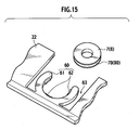
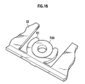
- the formation of the positioning portion 51 is not limited thereto. As shown in FIGS. 15 and 16, the positioning portion can be of clip type.
- a U-shape positioning portion 61 is formed in stead of perforating the electrode supporting portion 22.
- the U-shape positioning portion 61 has an inner circumference longer than a half of the outer circumference of the conductive washer 7 or the insulating washer 8.
- Protruding portions 62 are protruding from the positioning portion 61. Similarly to the foregoing protruding portions 52, the protruding portions 62 protrude into the groove 70 or 80 when the conductive washer 7 or the insulating washer 8 is fit into the positioning portion 61. The widths of the protruding portions 62 are smaller than those of the grooves 70 and 80.
- Clearances 63 are provided between the periphery of the positioning portion 61 and the electrode supporting portion 22. With these clearances 63, the clip-like positioning portion 61 opens when, for example, the conductive washer 7 is pushed towards the positioning portion 61. Thus, the conductive washer 7 is fit into the positioning portion 61 and held.
- the state where the conductive washer 7 has been fit into the positioning portion 61 is similar to the state shown in FIG. 14. Therefore, the conductive washer 7 can swing in the stacking direction without allowing the protruding portions 62 to be disengaged from the groove 70.
- the insulating washer 8 can also be held by the holding member 60 in the similar manner.
- the holding member As described so far, by forming the holding member into the clip type, the conductive washer 7 and the insulating washer 8 can be held by the holding member 60 more easily. Therefore, work efficiency is improved.
Landscapes
- Chemical & Material Sciences (AREA)
- Chemical Kinetics & Catalysis (AREA)
- Electrochemistry (AREA)
- General Chemical & Material Sciences (AREA)
- Engineering & Computer Science (AREA)
- Manufacturing & Machinery (AREA)
- Connection Of Batteries Or Terminals (AREA)
- Battery Mounting, Suspending (AREA)
Abstract
Description
- The present invention relates to battery frames used when stacking flat cells to form a battery, and a battery in which the frames are used.
- A plurality of single cells is combined in series or parallel to form a battery or a module battery with high power and capacity. For example, it is known that a plurality of flat single cells, each having an electric-power generating element covered with laminate films, is connected to each other in series or parallel to form a battery with high power and capacity (see Japanese Patent Laid-Open Publication No. 2001-256939). A flat single cell in which an electric-power generating element is covered with laminate films is called a laminate cell.
- Where a battery is formed using laminate cells of this kind, a plurality of laminate cells is located on the same plane, a plurality of sets of these laminate cells on the same plane is further stacked, and then these laminate cells are connected to each other in series or parallel. By stacking the laminate cells like this, a battery with higher power and capacity can be formed.
- When assembling this stack-type battery, locating and stacking laminate cells one by one results in poor workability. Therefore, laminate cells are located on a plate-like frame and a plurality of frames where the cells are located is stacked, thus improving workability in assembling a stack-type battery.
- Further, in order to electrically connect the cells located on neighboring frames in the stacking direction, washers made of a conductive material (conductive washers) may be incorporated in the frames at positions where electrode tabs of the laminate cells lie. To electrically insulate cells, washers made of insulating material (insulating washers) may be incorporated in the frames. When electrically connecting or insulating the laminate cells located on neighboring frames in the stacking direction, the frames, where the laminate cells are mounted, are stacked and the frames or washers are pressed from the top and bottom of the stack. This ensures that the electrode tabs and the washers come into contact with to each other, enabling the neighboring cells to be electrically connected or insulated from each other.
- Where conductive washers and insulating washers are incorporated into frames as described above, the washers are fixed to the frames by an adhesive or the like. If the washers and laminate cells have the same height, no loads are applied to the frames.
- However, dimensional variations of laminate cells in the height direction (stacking direction) are generally large. Therefore, it is difficult to allow heights of washers and laminate cells to meet each other. Where a height dimension of a laminate cell is larger than that of a washer, too much force is applied to a frame as the frame is pulled towards the washer, because the washer is firmly fixed to the frame. As a result, the frame is deformed.
- When the frame is deformed, a reaction force is generated in the frame, which may cause a failure or difficulty to connect the washer and an electrode tab of a laminate cell. Due to this, a circuit is cut off and resistance increases, thus deteriorating characteristics of the battery.
- Further, an above-described frame where washers are incorporated is also deformed when the washers has low parallelism to the frame.
- The present invention has been accomplished in the light of the above circumstances. An object of the present invention is to provide a battery frame which does not lower workability when assembling a battery and prevents deformation thereof, and a battery in which the frame is used.
- The first aspect of the present invention provides a battery frame comprising: any one of a conductive member and an insulating member which are sandwiched between electrode tabs of flat cells arranged in a stacking direction when a battery is formed, the conductive member electrically connecting the flat cells to each other and the insulating member electrically insulating the flat cells from each other; a holding member which holds any one of the conductive member and the insulating member so that the conductive member or the insulating member can swing in the stacking direction; and an electrode supporting portion in which the holding member is provided and which supports each of the electrode tabs of the flat cells.
- The second aspect of the present invention provides a battery comprising: a plurality of flat cells; and a plurality of frames stacked while the flat cells are mounted and positioned thereon, wherein each of the frames includes; any one of a conductive member and an insulating member which are sandwiched between electrode tabs of flat cells arranged in a stacking direction when the battery is formed, the conductive member electrically connecting the flat cells to each other and the insulating member electrically insulating the flat cells from each other; a holding member which holds any one of the conductive member and the insulating member so that the conductive member or the insulating member can swing in the stacking direction; and an electrode supporting portion in which the holding member is provided and which supports each of the electrode tabs of the flat cells.
- The third aspect of the present invention provides a battery frame, comprising: any one of a conductive member and an insulating member which are sandwiched between electrode tabs of flat cells arranged in a stacking direction when a battery is formed, the conductive member electrically connecting the flat cells to each other and the insulating member electrically insulating the flat cells from each other; holding means for holding any one of the conductive member and the insulating member so that the conductive member or the insulating member can swing in the stacking direction; and an electrode supporting portion in which the holding means is provided and which supports each of the electrode tabs of the flat cells.
- The invention will now be described with reference to the accompanying drawings wherein;
- FIG. 1 is a perspective view showing a battery of the present invention;
- FIG. 2 is a cross-sectional view taken along the line II-II of the battery shown in FIG 1;
- FIG. 3 is a perspective view showing a single cell to be incorporated in the battery of the present invention;
- FIG. 4 is a perspective view showing how to locate single cells on a battery frame of the present invention;
- FIG. 5 is a plan view showing a state where the single cells are located on the frame;
- FIG. 6 is a view showing a circuit structure formed within the battery;
- FIG. 7 is a plan view showing a holding member which holds a washer;
- FIG. 8 is a perspective view showing the holding member which holds a washer;
- FIG. 9 is a plan view showing another example of the holding member;
- FIG. 10 is a perspective view showing the another example of the holding member;
- FIG. 11 is a perspective view showing a fitting-in type holding member;
- FIG. 12 is an enlarged view showing the fitting-in type holding member;
- FIG. 13 is a cross-sectional view showing a state where a washer is fitted into the holding member;
- FIG. 14 is a perspective view showing another example of the fitting-in type holding member;
- FIG. 15 is a perspective view showing a clip-type holding member; and
- FIG. 16 is a perspective view showing a state where a washer is held by the clip-type holding member.
-
- The present invention is described below with reference to drawings.
- As for the first embodiment, the entire battery to which the present invention is applied is first described, and then each constituent will be detailed.
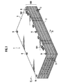
- As shown in FIG. 1, a
cell unit 100, made of a plurality of plate-shaped battery frames 2 stacked in the thickness direction, is sandwiched and pressed withheat sinks 3 from both sides in the stacking direction, and thecell unit 100 and theheat sinks 3 are held together, thus forming a battery 1. - As shown in FIGS. 4 and 5, four flat
single cells 10 are arranged on eachframe 2. Theframes 2 in this state are stacked so that the battery 1 is constructed. In the battery 1, for example, 24 frames are stacked and anintermediate heat sink 5 is interposed between every six frames in the stacking direction. This means that, in each battery 1, 24 sets of four parallel-located single cells are stacked. Therefore, each battery 1 has 96 single cells in total. - Six pressure units for connecting both
heat sinks nuts 6, thus fixing theheat sinks nuts 6. By attaching this unit between theheat sinks cell unit 100. - The stack construction of the battery 1 is shown in FIG. 2. This drawing simplifies the construction for easy understanding of the present invention. In this drawing, there are only four
frames 2 between theheat sinks heat sinks 3 and 4 in this embodiment. - As shown in FIG. 2, a layer of
single cells 10 is located on eachframe 2, and theseframes 2 are stacked within the battery 1. As shown in FIG. 3, thesingle cell 10 is flat, and a positive electrode tab 11 and anegative electrode tab 12 are drawn out from the flat body. The positive electrode tab 11 and thenegative electrode tab 12 are connected to an electric-power generating element within thesingle cell 10, respectively. Throughholes negative electrode tabs 11 and 12, respectively. - As shown in FIG. 2, in the
single cell 10, the positive electrode tab 11 and thenegative electrode tab 12 are alternately located in the stacking direction. The positive andnegative electrode tabs 11 and 12, which are alternately located, are connected to each other on the right and left sides in FIG. 2. This means that thesingle cells 10 are connected to each other in series in the stacking direction. A method of connecting the neighboringsingle cells 10 to each other in the stacking direction is as follows. - An opening
portion 21 is provided in eachframe 2 on the left side in FIG. 2. At thisopening portion 21, the positive andnegative electrode tabs 11 and 12 of thesingle cells 10 neighboring each other in the stacking direction are joined together by ultrasonic welding. At theopening portion 21, thesingle cell 10 is connected only to any one of thesingle cells 10 on the upper and lower layers. For example, the positive electrode tab 11 of the first layer and thenegative electrode tab 12 of the second layer are joined together by ultrasonic welding at the openingportion 21, and the positive electrode tab 11 of the third layer and thenegative electrode tab 12 of the fourth layer are joined together by ultrasonic bonding at the openingportion 21. Accordingly, on the left side in the drawing, the positive andnegative electrode tabs 11 and 12 neighboring each other in the stacking direction are electrically connected to each other by ultrasonic welding. - Meanwhile, on the right side of FIG. 2, a conductive washer 7 (a conductive member) or an insulating washer 8 (an insulating member) is located in each
frame 2. The thicknesses of these washers are the same or larger those of theframes 2. Theframes 2 are stacked so that theconductive washer 7 and the insulatingwasher 8 are arranged alternately in the stacking direction. The positive andnegative electrode tabs 11 and 12, which sandwich theconductive washer 7, are thus electrically connected to each other, and the positive andnegative electrode tabs 11 and 12, which sandwich the insulatingwasher 8, are insulated from each other. For example, theconductive washer 7 is located between the positive electrode tab 11 of the second layer and thenegative electrode tab 12 of the third layer, and the insulatingwasher 8 is located between thenegative electrode tab 12 of the third layer and the positive electrode tab 11 of the fourth layer. Accordingly, on the right side of the drawing, the positive electrode tab 11 and thenegative electrode tab 12 neighboring each other in the stacking direction are electrically connected to each other through theconductive washer 7. - Each of the
conductive washers 7 and the insulatingwashers 8 is held by a holding member provided in theframe 2 so that the washers can swing in the stacking direction. The holding member will be described later. - A
bolt 9 is inserted though theconductive washers 7 and the insulatingwashers 8 as well as the positive electrode tabs 11 and thenegative electrode tabs 12. In eachbolt 9, at least an area which comes into contact with theconductive washers 7 and the insulatingwashers 8, is covered with insulating members. Both ends of thebolt 9 are fastened by the nuts 90. Therefore, theconductive washers 7 and the insulatingwashers 8 are pressed from both sides in the stacking direction, ensuring that theconductive washer 7 or the insulatingwasher 8 and the positive electrode tab 11 or thenegative electrode tab 12 are connected to each other. - Since the center portion of each
frame 2 is open, the external surfaces of thesingle cells 10 neighboring in the stacking direction come into direct contact with each other within the battery 1. - A bus-
bar 91 is inserted between the insulatingwasher 8 of the lowermost layer and theheat sink 3. The bus-bar 91 allows the neighboringcell units 100 to be electrically connected to each other. Therefore, all 96single cells 10 are connected to each other in series within the battery 1. - As shown in FIG. 6, in the battery 1, the single cells located on the
frames 2 are serially connected to each other in the stacking direction, and thecell units 100 are connected to each other through the bus-bar 91, forming a single battery with high power.Reference numeral 101 in the drawing represents a negative electrode terminal of the battery and Reference numeral 102 represents a positive electrode terminal of the battery. - Each constituent of the battery is detailed below.
- The
single cell 10 used in this embodiment is a flat secondary cell having a rectangular shape as shown in FIG. 3 and provided with an electric-power generating element therein in which at least a positive electrode plates and a negative electrode plates are alternately stacked. For example, thesingle cell 10 has a construction disclosed in Japanese Patent Laid-Open Publication No. 2003-059486. Laminate films are used as sheath members for thesingle cell 10. Further, the electric-power generating element within thesingle cell 10 is sealed by joining the outer peripheries of the laminate films by thermal bonding. - The positive electrode tab 11 and the
negative electrode tab 12 are drawn out from both sides of thesingle cell 10 in the longitudinal direction. The positive electrode tab 11 is constituted by, for example, an about 0.2 mm-thick aluminum sheet. Thenegative electrode tab 12 is constructed by, for example, an about 0.2 mm-thick copper sheet. The positive andnegative electrode tabs 11 and 12 are provided with the throughholes bolts 9 are inserted. The outer periphery of thesingle cell 10, which has been joined together by thermal bonding, is positioned on the frame and supported. The direction of stacking thesingle cells 10 is the same as the direction of stacking the positive and negative electrode plates which construct the electric-power generating element. - In the present invention, the battery 1 is configured by single cells, each having electrode tabs of different polarities on the two opposite sides of the cell as shown in FIG. 3. However, the battery 1 may be constructed by using single cells in which electrode tabs of different polarities are attached only on one side as disclosed in Japanese Patent Laid-Open Publication No. 2003-059486. Where this type of single cells are used, however, the structure of the frame and a method of connecting the single cells will be largely different from those of this embodiment. In this embodiment, a single flat cell is used as the single cell. However, a plurality of cells, which are connected to each other in series, parallel, or both in series and parallel, may be held on the frame as the single cell.
- As shown in FIGS. 1 and 2, the heat sinks used in this embodiment are of two types: the
heat sinks 3 located on the uppermost and lowermost layers; and theintermediate heat sink 5, at least one of which is interposed between the stacked frames 2. - Both the
heat sinks heat sink 5 has air vents penetrating therethrough in the longitudinal direction so as to improve heat dissipation efficiency. - Locating pins for positioning the stacked frames are provided at four corners of the
heat sinks 3 on the lowermost layers. Therefore, of course, theframes 2 are provided with holes (not shown) through which the locating pins are inserted. When stacking theframes 2 onto theheat sink 3, these locating pins are inserted into the holes of theframes 2 for positioning of the frames. - In addition to the role of heat dissipation boards, the
heat sinks 3 also play a role to apply appropriate surface pressure to thecell unit 100 and hold thecell unit 100 integrally with the heat sinks 3. The pressure units are attached between theheat sinks 3 in order to apply surface pressure to thecell unit 100. Each pressure unit has a tension coil spring and spring fixing portions, each being screwed with the end of the tension coil spring so that the ends of the spring are fixed to the heat sinks. - The tension coil spring is fixed to the
heat sinks 3 so that the tension coil spring is extended between the heat sinks 3. Hence, surface pressure is applied to thecell unit 100 between the heat sinks 3. - The
battery frame 2 used in this embodiment has electrode supportingportions 22 which support the positive electrode tabs 11 and thenegative electrode tabs 12 of thesingle cells 10. Theconductive washers 7 or insulatingwashers 8 are located on theelectrode supporting portions 22 on one side of the frame, respectively. This is to connect thesingle cells 10 to each other in the stacking direction as stated earlier. The thickness dimension (dimension in the stacking direction) of theframe 2 is smaller than those of theconductive washers 7 or the insulatingwashers 8. This is because, if the thickness dimensions of theconductive washers 7 are not larger than that of theframe 2, the positive electrode tab 11 andnegative electrode tab 12 cannot be electrically continuous. - FIG. 5 explains a case where the
conductive washers 7 are held on theframe 2. However, the insulatingwashers 8 may, of course, be held in theframe 2. - The
conductive washers 7 are held by holdingmembers 25A formed in theelectrode supporting portions 22. - As shown in FIGS. 5, 7 and 8, each holding
member 25A is formed in eachelectrode supporting portion 22 and includes acircular portion 26A and a connectingportion 27A. - The
circular portion 26A is formed by making a circular cut through theelectrode supporting portion 22, and theconductive washer 7 or insulatingwasher 8 can be fitted to the center of the circle. The connectingportion 27A swingably connects an end of thecircular portion 26A to theelectrode supporting portion 22. - As shown in FIG. 7, in the first embodiment, the holding
member 25A is formed integrally with theelectrode supporting portion 22. In other words, thecircular portion 26A and the connectingportion 27A are formed by making a keyhole-shaped cut through theelectrode supporting portion 22 so that one end of the connectingportion 27A is not detached from theelectrode supporting portion 22. Therefore, no member other than theelectrode supporting portion 22 is used to form the holdingmember 25A. - The connecting
portion 27A holds only a part of thecircular portion 26A. Therefore, as the connectingportion 27A swings due to elasticity, thecircular portion 26A can also swing vertically. This means that, while holding theconductive washer 7 or the insulatingwasher 8, the holdingmember 25A can allow theconductive washer 7 or the insulatingwasher 8 to swing in the stacking direction. - As described above, in the present invention, the
conductive washer 7 and the insulatingwasher 8 is not firmly fixed to the battery flame but held to be able to swing in the stacking direction. Accordingly, the following effects can be obtained. - Even where the heights of the
conductive washers 7 and the insulatingwashers 8 are different from those of thesingle cells 10, in other words, even where the heights of thesingle cells 10 are larger than those of theconductive washers 7 and the insulatingwashers 8, theframe 2 is not deformed during the formation of the battery 1. When thebolt 9 is inserted through theconductive washers 7 or the insulatingwashers 8 as well as the positive electrode tabs 11 or thenegative electrode tabs 12 and fastened with the nuts 90 at both ends thereof, height differences between thesingle cells 10 and the conductive and insulatingwashers conductive washers 7 and the insulatingwashers 8. Therefore, no load is applied to theframes 2. Since no load is applied to theframes 2, it is possible to prevent a situation where a specific fastening force cannot be obtained due to a reaction force of theframe 2 even if thebolt 9 is fastened with nuts 6. - Moreover, even if the position of the
frame 2 is somewhat tilted, theconductive washers 7 can move to appropriate positions by the swing. This ensures that theconductive washer 7 and the positive electrode tab 11 or thenegative electrode tab 12 are electrically continuous. It is also possible to prevent a failure or difficulty to allow theconductive washer 7 and the positive electrode tab 11 or thenegative electrode tab 12 to come into contact with each other due to deformation of theframe 2. - In addition, when the
conductive washers 7 and the insulatingwashers 8 are attached to theframe 2, careful adjustment of positioning accuracy of these washes are unnecessary since it is automatically adjusted by the swing of theconductive washers 8 and the insulatingwashers 7 to some extent. - Moreover, in the first embodiment, the holding
member 25A for holding theconductive washer 7 or the insulatingwasher 8 is formed by making a cut through theelectrode supporting portion 22. Therefore, the holdingmember 25A is easily formed, which realizes good working efficiency in forming the holdingmember 25A. Thus, manufacturing costs are reduced. - Furthermore, in the foregoing embodiment, description was given regarding the case where the
conductive washers 7 are used as conductive members and the insulatingwashers 8 are used as insulating members. However, the conductive members and the insulating members are not limited to those having a washer shape. - In the first embodiment, the holding
member 25A is formed integrally with theelectrode supporting portion 22. However, the formation thereof is not limited to this. - The holding member can also be formed separately from the
electrode supporting portion 22. An example of such formation is shown in FIGS. 9 and 10. - As shown in FIGS. 9 and 10, a keyhole-shaped hole is bored through the
electrode supporting portion 22 and then a holdingmember 25B is provided in the hole. - The holding
member 25B includes acircular portion 26B, into which theconductive washer 7 or the insulatingwasher 8 is fitted, and a connectingportion 27B connecting thecircular portion 26B to theelectrode supporting portion 22. Unlike the foregoing connectingportion 27A, the connectingportion 27B is separated from theelectrode supporting portion 22. However, similarly to the connectingportion 27A, the connectingportion 27B swingably holds thecircular portion 26B by its elasticity. - Therefore, the holding
member 25B can provide effects similar to those stated earlier. However, formation of the holdingmember 25B is not so easy as the foregoing holdingmember 25A since the connectingportion 27B is separated from theelectrode supporting portion 22. - In the first embodiment, the
circular portions conductive washers 7 and the insulatingwashers 8 are fitted, are able to swing, so that theconductive washers 7 and the insulatingwashers 8 are also able to swing relative to theframe 2. In the second embodiment,conductive washers 7 and insulatingwashers 8 are allowed to swing without being fitted into thecircular portion - Described below are only a holding member, a
conductive washer 7 and an insulatingwasher 8. Other parts are the same as those of the first embodiment. - As shown in FIGS. 11, 12 and 14, a holding
member 50 according to the second embodiment includes apositioning portion 51, protrudingportions 52, andrelief portions 53. The positioningportion 51 is provided by perforating a part of theelectrode supporting portion 22 and fitted to the outer edge of aconductive washer 7 or an insulatingwasher 8. The protrudingportions 52 protrude from the positioningportion 51 towards theconductive washer 7 or the insulatingwasher 8 when theconductive washer 7 or the insulatingwasher 8 is located in thepositioning portion 51. Therelief portions 53 are formed on the periphery of thepositioning portion 51 by opening holes through theelectrode supporting portion 22. Therelief portions 53 allow thepositioning portion 51 to deform so that theconductive washer 7 or the insulatingwasher 8 can be fit into thepositioning portion 51. - As shown in FIG. 13, in the second embodiment,
grooves conductive washer 7 and the insulatingwasher 8, respectively. The widths W1 of thegroove portions 52 of the holdingmember 50. - When attempting to fit the
conductive washer 7 into thepositioning portion 51 as shown by an arrow in FIG. 11, theconductive washer 7 is not easily fit thereinto because the protrudingportions 52 catch theconductive washer 7. However, once a force is applied, the protrudingportions 52 are deformed as if they escape towards therelief portions 53. Theconductive washer 7 is thus fit into thepositioning portion 51. The insulatingwasher 8 is fit into thepositioning portion 51 in the same manner. - FIG. 13 shows a state where the
conductive washer 7 has been fit to thepositioning portion 51. As shown in FIG. 13, the protrudingportions 52 of the holdingmember 50 protrude into thegroove 70 of theconductive washer 7. Once a force is applied to allow theprotrude portions 52 to enter thegroove 70, theconductive washer 7 is not removed from the holdingmember 50 unless a force is applied again to deform the protrudingportions 52. - Since the width W1 of the
groove 70 is larger than the widths W2 of the protrudingportions 52, theconductive washer 7 can swing in the stacking direction without allowing the protrudingportions 52 to be disengaged from thegroove 70. - As described so far, in the second embodiment, the holding
members 50 hold theconductive washers 7 and the insulatingwashers 8 so that these washers can swing in the stacking direction. Therefore, the holdingmembers 50 can provide effects similar to those of the first embodiment. To be more specific, even though the heights of theconductive washers 7 and the insulatingwashers 8 are different from the heights of thesingle cells 10, theframes 2 are not deformed during the formation of the battery 1. Since no load is applied to theframes 2, it is possible to prevent a situation where a specific fastening force cannot be obtained due to a reaction force of theframe 2 even if thebolt 9 is fastened with nuts 6. - Further, even if the position of the
frame 2 is somewhat tilted, theconductive washers 7 can move to appropriate positions by the swing, which ensures that theconductive washer 7 and the positive electrode tab 11 or thenegative electrode tab 12 are electrically continuous. It is also possible to prevent a failure or difficulty to allow theconductive washer 7 and the positive electrode tab 11 or thenegative electrode tab 12 to come into contact with each other due to deformation of theframe 2. - In the second embodiment, the
relief portions 53 are formed by making holes in theelectrode supporting portion 22. However, the formation of therelief portions 53 is not limited thereto. As shown in FIG. 14, therelief portions 53 may be formed by making cuts in theelectrode supporting portion 22 on the periphery of thepositioning portion 51. - Moreover, in the second embodiment, the positioning
portion 51 is provided by perforating a part of theelectrode supporting portion 22. However the formation of thepositioning portion 51 is not limited thereto. As shown in FIGS. 15 and 16, the positioning portion can be of clip type. - As shown in FIG. 15, in a holding
member 60 of the clip type, aU-shape positioning portion 61 is formed in stead of perforating theelectrode supporting portion 22. TheU-shape positioning portion 61 has an inner circumference longer than a half of the outer circumference of theconductive washer 7 or the insulatingwasher 8. - Protruding
portions 62 are protruding from the positioningportion 61. Similarly to the foregoing protrudingportions 52, the protrudingportions 62 protrude into thegroove conductive washer 7 or the insulatingwasher 8 is fit into thepositioning portion 61. The widths of the protrudingportions 62 are smaller than those of thegrooves -
Clearances 63 are provided between the periphery of thepositioning portion 61 and theelectrode supporting portion 22. With theseclearances 63, the clip-like positioning portion 61 opens when, for example, theconductive washer 7 is pushed towards the positioningportion 61. Thus, theconductive washer 7 is fit into thepositioning portion 61 and held. - The state where the
conductive washer 7 has been fit into thepositioning portion 61 is similar to the state shown in FIG. 14. Therefore, theconductive washer 7 can swing in the stacking direction without allowing the protrudingportions 62 to be disengaged from thegroove 70. The insulatingwasher 8 can also be held by the holdingmember 60 in the similar manner. - As described so far, by forming the holding member into the clip type, the
conductive washer 7 and the insulatingwasher 8 can be held by the holdingmember 60 more easily. Therefore, work efficiency is improved. - The entire content of a Japanese Patent Application No. P2004-099328 with a filing date of March 30, 2004 is herein incorporated by reference.
- Although the invention has been described above by reference to certain embodiments of the invention, the invention is not limited to the embodiments described above will occur to these skilled in the art, in light of the teachings. The scope of the invention is defined with reference to the following claims.
Claims (12)
- A battery frame, comprising:any one of a conductive member (7) and an insulating member (8) which are sandwiched between electrode tabs (11, 12) of flat cells (10) arranged in a stacking direction when a battery (1) is formed, the conductive member (7) electrically connecting the flat cells (10) to each other and the insulating member (8) electrically insulating the flat cells (10) from each other;a holding member (25A, 25B, 50, 60) which holds any one of the conductive member (7) and the insulating member (8) so that the conductive member (7) or the insulating member (8) can swing in the stacking direction; andan electrode supporting portion (22) in which the holding member (25A, 25B, 50, 60) is provided and which supports each of the electrode tabs (11, 12) of the flat cells (10).
- A battery frame according to claim 1,
wherein a thickness of the frame (2) in the stacking direction is smaller than those of the conductive member (7) and the insulating member (8). - A battery frame according to claims 1. or 2,
wherein the holding member (25A, 25B) includes:a circular portion (26A, 26B) which is formed by making a circular cut through the electrode supporting portion (22) and to which the conductive member (7) or the insulating member (8) is fitted; anda connecting portion (27A, 27B) which swingably connects one end of the circular portion (26A, 26B) to the electrode supporting portion (22). - A battery frame according to claim 3,
wherein the circular portion (26A) and the connecting portion (27A) are formed integrally with the electrode supporting portion (22). - A battery frame according to claims 1 or 2,
wherein the holding member (50, 60) includes:wherein a groove (70, 80), which has width (W1) larger than width (W2) of the protruding portion (52, 62), is formed on a circumference surface of the conductive member (7) or the insulating member (8), and the conductive member (7) or the insulating member (8) is fitted into the positioning portion (51, 61) so that the protruding portion (52, 62) goes into the groove (70, 80).a positioning portion (51, 61) which is fitted to an outer edge of the conductive member (7) or the insulating member (8) and positions the conductive member (7) or the insulating member (8) in a direction almost perpendicular to the stacking direction; anda protruding portion (52, 62) which protrudes from the positioning portion (51, 61) towards the conductive member (7) or the insulating member (8), and - A battery frame according to claim 5,
wherein a relief portion (53, 63) is provided on a periphery of the positioning portion (51, 61) so that the positioning portion (51, 61) can be deformed in a direction perpendicular to the stacking direction. - A battery, comprising:wherein each of the frames (2) includes;a plurality of flat cells (10); anda plurality of frames (2) stacked while the flat cells (10) are mounted and positioned thereon,
any one of a conductive member (7) and an insulating member (8) which are sandwiched between electrode tabs (11, 12) of flat cells (10) arranged in a stacking direction when the battery (1) is formed, the conductive member (7) electrically connecting the flat cells (10) to each other and the insulating member (8) electrically insulating the flat cells (10) from each other;
a holding member (25A, 25B, 50, 60) which holds any one of the conductive member (7) and the insulating member (8) so that the conductive member (7) or the insulating member (8) can swing in the stacking direction; and
an electrode supporting portion (22) in which the holding member (25A, 25B, 50, 60) is provided and which supports each of the electrode tabs (11, 12) of the flat cells (10). - A battery according to claim 7,
wherein a thickness of the frame (2) in the stacking direction is smaller than those of the conductive member (7) and the insulating member (8). - A battery according to claims 7 or 8,
wherein the holding member (25A, 25B, 50, 60) includes:a circular portion (26A, 26B) which is formed by making a circular cut through the electrode supporting portion (22) and to which the conductive member (7) or the insulating member (8) is fitted; anda connecting portion (27A, 27B) which swingably connects one end of the circular portion (26A, 26B) to the electrode supporting portion (22). - A battery according to claim 9,
wherein the circular portion (26A, 26B) and the connecting portion (27A, 27B) are formed integrally with the electrode supporting portion (22). - A battery according to claims 7 or 8,
wherein the holding member (25A, 25B, 50, 60) includes:wherein a groove (70, 80), which has width (W1) larger than width (W2) of the protruding portion (52, 62), is formed on a circumference surface of the conductive member (7) or the insulating member (8), and the conductive member (7) or the insulating member (8) is fitted into the positioning portion (S1, 61) so that the protruding portion (52, 62) goes into the groove (70, 80).a positioning portion (51, 61) which is fitted to an outer edge of the conductive member (7) or the insulating member (8) and positions the conductive member (7) or the insulating member (8) in a direction almost perpendicular to the stacking direction; anda protruding portion (52, 62) which protrudes from the positioning portion (51, 61) towards the conductive member (7) or the insulating member (8), and - A battery according to claim 11,
wherein a relief portion (53, 63) is provided on a periphery of the positioning portion (51, 61) so that the positioning portion (51, 61) can be deformed in a direction perpendicular to the stacking direction.
Applications Claiming Priority (2)
| Application Number | Priority Date | Filing Date | Title |
|---|---|---|---|
| JP2004099328A JP3897029B2 (en) | 2004-03-30 | 2004-03-30 | Battery frame and battery pack |
| JP2004099328 | 2004-03-30 |
Publications (1)
| Publication Number | Publication Date |
|---|---|
| EP1583167A1 true EP1583167A1 (en) | 2005-10-05 |
Family
ID=34879975
Family Applications (1)
| Application Number | Title | Priority Date | Filing Date |
|---|---|---|---|
| EP05006427A Withdrawn EP1583167A1 (en) | 2004-03-30 | 2005-03-23 | Battery frame and battery |
Country Status (5)
| Country | Link |
|---|---|
| US (1) | US7288341B2 (en) |
| EP (1) | EP1583167A1 (en) |
| JP (1) | JP3897029B2 (en) |
| KR (1) | KR100681298B1 (en) |
| CN (1) | CN1327543C (en) |
Cited By (5)
| Publication number | Priority date | Publication date | Assignee | Title |
|---|---|---|---|---|
| WO2010145742A1 (en) * | 2009-06-19 | 2010-12-23 | Li-Tec Battery Gmbh | Battery arrangement and method for the production thereof |
| DE102009058444A1 (en) | 2009-12-16 | 2011-06-22 | Li-Tec Battery GmbH, 01917 | Battery housing for receiving electrochemical energy storage devices |
| EP2390946A3 (en) * | 2010-05-24 | 2012-01-11 | Japan Aviation Electronics Industry Limited | Conductor-connecting washer, connection mechanism using the same, and method of manufacturing conductor-connecting washer |
| WO2013060314A1 (en) * | 2011-10-28 | 2013-05-02 | Li-Tec Battery Gmbh | Cell frame of an electrochemical cell, electrochemical cell having a cell frame, and battery having corresponding electrochemical cells |
| EP2654102A3 (en) * | 2012-04-18 | 2014-07-30 | Hitachi Maxell, Ltd. | Battery stack |
Families Citing this family (32)
| Publication number | Priority date | Publication date | Assignee | Title |
|---|---|---|---|---|
| JP4992244B2 (en) * | 2005-04-07 | 2012-08-08 | 日産自動車株式会社 | Battery module and battery pack |
| WO2007043510A1 (en) * | 2005-10-14 | 2007-04-19 | Nec Corporation | System for receiving film-coated electric device |
| KR100920210B1 (en) * | 2006-02-09 | 2009-10-05 | 주식회사 엘지화학 | Frame member for battery module manufacturing |
| JP2007257849A (en) * | 2006-03-20 | 2007-10-04 | Hitachi Maxell Ltd | Battery module of laminated exterior flat battery |
| US20090181298A1 (en) * | 2008-01-10 | 2009-07-16 | Eaglepicher Energy Products Corporation | Integral electrochemical device |
| JP4767291B2 (en) * | 2008-07-07 | 2011-09-07 | トヨタ自動車株式会社 | Battery holding frame and battery assembly |
| US9028986B2 (en) | 2009-01-07 | 2015-05-12 | A123 Systems Llc | Fuse for battery cells |
| US8257848B2 (en) | 2009-01-12 | 2012-09-04 | A123 Systems, Inc. | Safety venting mechanism with tearing tooth structure for batteries |
| DE102009010147A1 (en) * | 2009-02-23 | 2010-08-26 | Li-Tec Battery Gmbh | Galvanic cell |
| FR2943854B1 (en) * | 2009-03-26 | 2011-06-10 | Commissariat Energie Atomique | BIPOLAR BATTERY WITH IMPROVED OPERATION |
| KR101266617B1 (en) * | 2009-03-31 | 2013-05-22 | 미츠비시 쥬고교 가부시키가이샤 | Secondary battery and battery system |
| DE102009049043A1 (en) * | 2009-10-12 | 2011-04-14 | Li-Tec Battery Gmbh | Cell block with lateral support of the cells |
| EP2507891B1 (en) | 2009-12-04 | 2018-03-28 | A123 Systems LLC | Battery with integrated power management system and scalable battery cutoff component |
| JP5748190B2 (en) * | 2010-03-24 | 2015-07-15 | Necエナジーデバイス株式会社 | Battery unit and power supply device using the same |
| JP5577802B2 (en) * | 2010-04-07 | 2014-08-27 | 日産自動車株式会社 | Battery module |
| JP5626852B2 (en) * | 2010-05-19 | 2014-11-19 | Necエナジーデバイス株式会社 | Power supply |
| KR101271567B1 (en) * | 2010-08-16 | 2013-06-11 | 주식회사 엘지화학 | Battery Module of Structure Having Fixing Member Inserted into Through-Hole of Plates and Battery Pack Employed with the Same |
| CN104521026B (en) * | 2012-09-19 | 2017-07-07 | 日产自动车株式会社 | Battery pack |
| JP5929733B2 (en) * | 2012-12-10 | 2016-06-08 | 株式会社豊田自動織機 | Storage module and secondary battery module |
| JP6334516B2 (en) * | 2013-04-19 | 2018-05-30 | Necエナジーデバイス株式会社 | Battery manufacturing method and battery module |
| JP6020922B2 (en) * | 2013-05-08 | 2016-11-02 | 株式会社オートネットワーク技術研究所 | Power storage module |
| JP6237450B2 (en) | 2014-05-07 | 2017-11-29 | 株式会社オートネットワーク技術研究所 | Power storage module |
| US10020534B2 (en) | 2014-09-26 | 2018-07-10 | Johnson Controls Technology Company | Free floating battery cell assembly techniques for lithium ion battery module |
| US10103367B2 (en) | 2014-09-26 | 2018-10-16 | Johnson Controls Technology Company | Lithium ion battery module with free floating prismatic battery cells |
| JP6406983B2 (en) * | 2014-11-12 | 2018-10-17 | 三菱電機株式会社 | Semiconductor device and manufacturing method thereof |
| KR102393886B1 (en) * | 2016-04-20 | 2022-05-02 | 코버스 에너지 인코포레이티드 | An enclosure for a stack assembly including a battery cell carrier and a plurality of battery cell carriers |
| KR20180026945A (en) * | 2016-09-05 | 2018-03-14 | 주식회사 엘지화학 | Battery module and battery pack including the same |
| CN111477800A (en) * | 2020-04-30 | 2020-07-31 | 昆山宝创新能源科技有限公司 | Battery Modules, Battery Packs and Vehicles |
| CN111477829A (en) * | 2020-04-30 | 2020-07-31 | 昆山宝创新能源科技有限公司 | Battery Modules and Automotive |
| CN111477828A (en) * | 2020-04-30 | 2020-07-31 | 昆山宝创新能源科技有限公司 | Battery module and battery module and automobile having the same |
| JP7452484B2 (en) * | 2021-03-31 | 2024-03-19 | トヨタ自動車株式会社 | Power storage device |
| KR20250076175A (en) * | 2023-11-22 | 2025-05-29 | 주식회사 엘지에너지솔루션 | BMU Grounding Compart Comprising Boss hole and Ground Pin |
Citations (4)
| Publication number | Priority date | Publication date | Assignee | Title |
|---|---|---|---|---|
| JPH08171925A (en) * | 1994-12-19 | 1996-07-02 | Mitsubishi Electric Corp | Polymer electrolyte fuel cell |
| EP0930661A2 (en) * | 1998-01-14 | 1999-07-21 | Tai-Her Yang | The Electricity storage/discharge device with low internal resistance current collector structure |
| JP2001256939A (en) * | 2000-03-14 | 2001-09-21 | Matsushita Electric Ind Co Ltd | Battery pack |
| JP2003059486A (en) * | 2001-08-10 | 2003-02-28 | Matsushita Electric Ind Co Ltd | Stacked battery and method of manufacturing the same |
Family Cites Families (2)
| Publication number | Priority date | Publication date | Assignee | Title |
|---|---|---|---|---|
| AU6059273A (en) * | 1972-09-25 | 1975-03-27 | Dunlop Australia Ltd | Battery construction |
| US6358641B1 (en) * | 1999-08-20 | 2002-03-19 | Plug Power Inc. | Technique and arrangement to align fuel cell plates |
-
2004
- 2004-03-30 JP JP2004099328A patent/JP3897029B2/en not_active Expired - Fee Related
-
2005
- 2005-03-18 US US11/083,249 patent/US7288341B2/en not_active Expired - Fee Related
- 2005-03-22 CN CNB2005100548661A patent/CN1327543C/en not_active Expired - Fee Related
- 2005-03-23 EP EP05006427A patent/EP1583167A1/en not_active Withdrawn
- 2005-03-29 KR KR1020050026095A patent/KR100681298B1/en not_active Expired - Fee Related
Patent Citations (4)
| Publication number | Priority date | Publication date | Assignee | Title |
|---|---|---|---|---|
| JPH08171925A (en) * | 1994-12-19 | 1996-07-02 | Mitsubishi Electric Corp | Polymer electrolyte fuel cell |
| EP0930661A2 (en) * | 1998-01-14 | 1999-07-21 | Tai-Her Yang | The Electricity storage/discharge device with low internal resistance current collector structure |
| JP2001256939A (en) * | 2000-03-14 | 2001-09-21 | Matsushita Electric Ind Co Ltd | Battery pack |
| JP2003059486A (en) * | 2001-08-10 | 2003-02-28 | Matsushita Electric Ind Co Ltd | Stacked battery and method of manufacturing the same |
Non-Patent Citations (3)
| Title |
|---|
| PATENT ABSTRACTS OF JAPAN vol. 1996, no. 11 29 November 1996 (1996-11-29) * |
| PATENT ABSTRACTS OF JAPAN vol. 2000, no. 26 1 July 2002 (2002-07-01) * |
| PATENT ABSTRACTS OF JAPAN vol. 2003, no. 06 3 June 2003 (2003-06-03) * |
Cited By (8)
| Publication number | Priority date | Publication date | Assignee | Title |
|---|---|---|---|---|
| WO2010145742A1 (en) * | 2009-06-19 | 2010-12-23 | Li-Tec Battery Gmbh | Battery arrangement and method for the production thereof |
| DE102009058444A1 (en) | 2009-12-16 | 2011-06-22 | Li-Tec Battery GmbH, 01917 | Battery housing for receiving electrochemical energy storage devices |
| WO2011072793A1 (en) | 2009-12-16 | 2011-06-23 | Li-Tec Battery Gmbh | Battery case for receiving electrochemical energy-storage devices |
| EP2390946A3 (en) * | 2010-05-24 | 2012-01-11 | Japan Aviation Electronics Industry Limited | Conductor-connecting washer, connection mechanism using the same, and method of manufacturing conductor-connecting washer |
| CN102332644A (en) * | 2010-05-24 | 2012-01-25 | 日本航空电子工业株式会社 | Conductor connects pad, the bindiny mechanism that uses it and conductor connection gasket piece making method |
| US8303357B2 (en) | 2010-05-24 | 2012-11-06 | Japan Aviation Electronics Industry, Limited | Conductor-connecting washer, connection mechanism using the same, and method of manufacturing conductor-connecting washer |
| WO2013060314A1 (en) * | 2011-10-28 | 2013-05-02 | Li-Tec Battery Gmbh | Cell frame of an electrochemical cell, electrochemical cell having a cell frame, and battery having corresponding electrochemical cells |
| EP2654102A3 (en) * | 2012-04-18 | 2014-07-30 | Hitachi Maxell, Ltd. | Battery stack |
Also Published As
| Publication number | Publication date |
|---|---|
| US20050221177A1 (en) | 2005-10-06 |
| US7288341B2 (en) | 2007-10-30 |
| CN1677711A (en) | 2005-10-05 |
| JP2005285625A (en) | 2005-10-13 |
| KR20060044949A (en) | 2006-05-16 |
| KR100681298B1 (en) | 2007-02-09 |
| JP3897029B2 (en) | 2007-03-22 |
| CN1327543C (en) | 2007-07-18 |
Similar Documents
| Publication | Publication Date | Title |
|---|---|---|
| US7288341B2 (en) | Battery frame and battery | |
| US8586235B2 (en) | Battery module | |
| JP6091921B2 (en) | Battery module and battery pack | |
| JP5544931B2 (en) | Laminated cell battery structure | |
| JP5374979B2 (en) | Batteries and batteries | |
| JP2019046578A (en) | Method of manufacturing battery pack | |
| WO2014091998A1 (en) | Battery module and method for manufacturing battery module | |
| CN103594662B (en) | Secondary cell | |
| JP4461940B2 (en) | Assembled battery | |
| JP7799044B2 (en) | Cell unit, battery and vehicle | |
| WO2018143464A1 (en) | Battery module and method for producing battery module | |
| JP2018018629A (en) | Battery module | |
| JP6737577B2 (en) | Battery pack | |
| JP2010135148A (en) | Cell unit, battery module, and battery pack | |
| JP7210519B2 (en) | Battery cells and battery modules | |
| JP7284152B2 (en) | battery module | |
| WO2017014046A1 (en) | Battery module and battery pack | |
| JP4513451B2 (en) | Assembled battery | |
| JP2023008499A (en) | Power storage module and power storage pack | |
| JP2008243639A (en) | Battery pack with pressure holder | |
| JP6160202B2 (en) | Battery module | |
| JP2004349473A (en) | Capacitor unit | |
| JP4029819B2 (en) | Assembled battery | |
| JP2022026171A (en) | Power storage module, welding method, and manufacturing method of power storage module using welding method | |
| JP2015213027A (en) | Assembled battery and method of manufacturing the assembled battery |
Legal Events
| Date | Code | Title | Description |
|---|---|---|---|
| PUAI | Public reference made under article 153(3) epc to a published international application that has entered the european phase |
Free format text: ORIGINAL CODE: 0009012 |
|
| 17P | Request for examination filed |
Effective date: 20050323 |
|
| AK | Designated contracting states |
Kind code of ref document: A1 Designated state(s): AT BE BG CH CY CZ DE DK EE ES FI FR GB GR HU IE IS IT LI LT LU MC NL PL PT RO SE SI SK TR |
|
| AX | Request for extension of the european patent |
Extension state: AL BA HR LV MK YU |
|
| AKX | Designation fees paid |
Designated state(s): DE FR GB |
|
| GRAP | Despatch of communication of intention to grant a patent |
Free format text: ORIGINAL CODE: EPIDOSNIGR1 |
|
| STAA | Information on the status of an ep patent application or granted ep patent |
Free format text: STATUS: THE APPLICATION IS DEEMED TO BE WITHDRAWN |
|
| 18D | Application deemed to be withdrawn |
Effective date: 20100626 |