EP1582919A1 - Silver halide photosensitive material and photothermographic material - Google Patents
Silver halide photosensitive material and photothermographic material Download PDFInfo
- Publication number
- EP1582919A1 EP1582919A1 EP05005950A EP05005950A EP1582919A1 EP 1582919 A1 EP1582919 A1 EP 1582919A1 EP 05005950 A EP05005950 A EP 05005950A EP 05005950 A EP05005950 A EP 05005950A EP 1582919 A1 EP1582919 A1 EP 1582919A1
- Authority
- EP
- European Patent Office
- Prior art keywords
- group
- formula
- photothermographic material
- layer
- hydrogen atom
- Prior art date
- Legal status (The legal status is an assumption and is not a legal conclusion. Google has not performed a legal analysis and makes no representation as to the accuracy of the status listed.)
- Granted
Links
- -1 Silver halide Chemical class 0.000 title claims abstract description 350
- 229910052709 silver Inorganic materials 0.000 title claims abstract description 169
- 239000004332 silver Substances 0.000 title claims abstract description 169
- 239000000463 material Substances 0.000 title claims abstract description 149
- 125000004435 hydrogen atom Chemical group [H]* 0.000 claims abstract description 92
- GGCZERPQGJTIQP-UHFFFAOYSA-N sodium;9,10-dioxoanthracene-2-sulfonic acid Chemical compound [Na+].C1=CC=C2C(=O)C3=CC(S(=O)(=O)O)=CC=C3C(=O)C2=C1 GGCZERPQGJTIQP-UHFFFAOYSA-N 0.000 claims abstract description 73
- 125000001424 substituent group Chemical group 0.000 claims abstract description 69
- 239000003638 chemical reducing agent Substances 0.000 claims abstract description 45
- 229910052751 metal Chemical group 0.000 claims abstract description 22
- 239000002184 metal Chemical group 0.000 claims abstract description 22
- 125000004429 atom Chemical group 0.000 claims abstract description 17
- 125000000217 alkyl group Chemical group 0.000 claims description 86
- XLYOFNOQVPJJNP-UHFFFAOYSA-N water Substances O XLYOFNOQVPJJNP-UHFFFAOYSA-N 0.000 claims description 84
- 125000000623 heterocyclic group Chemical group 0.000 claims description 83
- 125000003118 aryl group Chemical group 0.000 claims description 63
- 238000011161 development Methods 0.000 claims description 57
- 125000003917 carbamoyl group Chemical group [H]N([H])C(*)=O 0.000 claims description 26
- 125000002252 acyl group Chemical group 0.000 claims description 20
- 125000004397 aminosulfonyl group Chemical group NS(=O)(=O)* 0.000 claims description 19
- 125000004453 alkoxycarbonyl group Chemical group 0.000 claims description 15
- 125000000472 sulfonyl group Chemical group *S(*)(=O)=O 0.000 claims description 15
- 230000031700 light absorption Effects 0.000 claims description 13
- IEQIEDJGQAUEQZ-UHFFFAOYSA-N phthalocyanine Chemical group N1C(N=C2C3=CC=CC=C3C(N=C3C4=CC=CC=C4C(=N4)N3)=N2)=C(C=CC=C2)C2=C1N=C1C2=CC=CC=C2C4=N1 IEQIEDJGQAUEQZ-UHFFFAOYSA-N 0.000 claims description 11
- 238000010521 absorption reaction Methods 0.000 claims description 6
- 239000010410 layer Substances 0.000 description 190
- 150000001875 compounds Chemical class 0.000 description 168
- 239000000243 solution Substances 0.000 description 142
- 238000000034 method Methods 0.000 description 133
- 239000000975 dye Substances 0.000 description 120
- 238000000576 coating method Methods 0.000 description 109
- 239000011248 coating agent Substances 0.000 description 107
- 239000006185 dispersion Substances 0.000 description 98
- 125000004432 carbon atom Chemical group C* 0.000 description 68
- OKKJLVBELUTLKV-UHFFFAOYSA-N Methanol Chemical compound OC OKKJLVBELUTLKV-UHFFFAOYSA-N 0.000 description 67
- 229920000126 latex Polymers 0.000 description 64
- 239000004816 latex Substances 0.000 description 64
- 239000002245 particle Substances 0.000 description 63
- 238000002360 preparation method Methods 0.000 description 57
- 230000018109 developmental process Effects 0.000 description 56
- 239000007864 aqueous solution Substances 0.000 description 54
- 150000003839 salts Chemical class 0.000 description 52
- BQCADISMDOOEFD-UHFFFAOYSA-N Silver Chemical compound [Ag] BQCADISMDOOEFD-UHFFFAOYSA-N 0.000 description 50
- 239000000839 emulsion Substances 0.000 description 45
- 229920000642 polymer Polymers 0.000 description 44
- 239000000126 substance Substances 0.000 description 41
- HEMHJVSKTPXQMS-UHFFFAOYSA-M Sodium hydroxide Chemical compound [OH-].[Na+] HEMHJVSKTPXQMS-UHFFFAOYSA-M 0.000 description 39
- 230000008569 process Effects 0.000 description 36
- 230000001235 sensitizing effect Effects 0.000 description 35
- 239000000203 mixture Substances 0.000 description 32
- 238000002156 mixing Methods 0.000 description 31
- 125000005843 halogen group Chemical group 0.000 description 30
- 239000011241 protective layer Substances 0.000 description 29
- 108010010803 Gelatin Proteins 0.000 description 28
- 206010070834 Sensitisation Diseases 0.000 description 28
- 229920000159 gelatin Polymers 0.000 description 28
- 235000019322 gelatine Nutrition 0.000 description 28
- 235000011852 gelatine desserts Nutrition 0.000 description 28
- 229910052757 nitrogen Inorganic materials 0.000 description 28
- 230000008313 sensitization Effects 0.000 description 28
- 230000000274 adsorptive effect Effects 0.000 description 27
- 239000008273 gelatin Substances 0.000 description 26
- PPBRXRYQALVLMV-UHFFFAOYSA-N Styrene Chemical compound C=CC1=CC=CC=C1 PPBRXRYQALVLMV-UHFFFAOYSA-N 0.000 description 24
- SQGYOTSLMSWVJD-UHFFFAOYSA-N silver(1+) nitrate Chemical compound [Ag+].[O-]N(=O)=O SQGYOTSLMSWVJD-UHFFFAOYSA-N 0.000 description 24
- 230000003595 spectral effect Effects 0.000 description 24
- 229920002451 polyvinyl alcohol Polymers 0.000 description 23
- 125000003396 thiol group Chemical group [H]S* 0.000 description 23
- 239000011230 binding agent Substances 0.000 description 22
- 229940125904 compound 1 Drugs 0.000 description 21
- 238000011156 evaluation Methods 0.000 description 20
- 239000004094 surface-active agent Substances 0.000 description 20
- IJGRMHOSHXDMSA-UHFFFAOYSA-N Atomic nitrogen Chemical compound N#N IJGRMHOSHXDMSA-UHFFFAOYSA-N 0.000 description 19
- 125000004433 nitrogen atom Chemical group N* 0.000 description 19
- 239000000047 product Substances 0.000 description 19
- 125000002496 methyl group Chemical group [H]C([H])([H])* 0.000 description 18
- 230000035945 sensitivity Effects 0.000 description 18
- 239000007787 solid Substances 0.000 description 18
- 239000002904 solvent Substances 0.000 description 18
- 239000004372 Polyvinyl alcohol Substances 0.000 description 17
- 238000006243 chemical reaction Methods 0.000 description 17
- 238000010438 heat treatment Methods 0.000 description 17
- 235000019422 polyvinyl alcohol Nutrition 0.000 description 17
- KFZMGEQAYNKOFK-UHFFFAOYSA-N Isopropanol Chemical compound CC(C)O KFZMGEQAYNKOFK-UHFFFAOYSA-N 0.000 description 16
- MCMNRKCIXSYSNV-UHFFFAOYSA-N Zirconium dioxide Chemical compound O=[Zr]=O MCMNRKCIXSYSNV-UHFFFAOYSA-N 0.000 description 16
- 125000001931 aliphatic group Chemical group 0.000 description 16
- 125000003545 alkoxy group Chemical group 0.000 description 16
- 229910052739 hydrogen Inorganic materials 0.000 description 16
- 239000001257 hydrogen Substances 0.000 description 16
- 238000007254 oxidation reaction Methods 0.000 description 16
- 239000002002 slurry Substances 0.000 description 16
- 230000015572 biosynthetic process Effects 0.000 description 15
- 239000003795 chemical substances by application Substances 0.000 description 15
- 239000012153 distilled water Substances 0.000 description 15
- 230000003647 oxidation Effects 0.000 description 15
- 125000001997 phenyl group Chemical group [H]C1=C([H])C([H])=C(*)C([H])=C1[H] 0.000 description 15
- 229920003048 styrene butadiene rubber Polymers 0.000 description 15
- LFQSCWFLJHTTHZ-UHFFFAOYSA-N Ethanol Chemical compound CCO LFQSCWFLJHTTHZ-UHFFFAOYSA-N 0.000 description 14
- 239000002253 acid Substances 0.000 description 14
- 239000000654 additive Substances 0.000 description 14
- 238000004132 cross linking Methods 0.000 description 14
- 239000010419 fine particle Substances 0.000 description 14
- NBVXSUQYWXRMNV-UHFFFAOYSA-N fluoromethane Chemical compound FC NBVXSUQYWXRMNV-UHFFFAOYSA-N 0.000 description 14
- 125000004104 aryloxy group Chemical group 0.000 description 13
- 229920001577 copolymer Polymers 0.000 description 13
- 125000001495 ethyl group Chemical group [H]C([H])([H])C([H])([H])* 0.000 description 13
- 125000001449 isopropyl group Chemical group [H]C([H])([H])C([H])(*)C([H])([H])[H] 0.000 description 13
- 239000000178 monomer Substances 0.000 description 13
- 239000003960 organic solvent Substances 0.000 description 13
- 238000012545 processing Methods 0.000 description 13
- KAKZBPTYRLMSJV-UHFFFAOYSA-N Butadiene Chemical compound C=CC=C KAKZBPTYRLMSJV-UHFFFAOYSA-N 0.000 description 12
- LYCAIKOWRPUZTN-UHFFFAOYSA-N Ethylene glycol Chemical compound OCCO LYCAIKOWRPUZTN-UHFFFAOYSA-N 0.000 description 12
- ZMXDDKWLCZADIW-UHFFFAOYSA-N N,N-Dimethylformamide Chemical compound CN(C)C=O ZMXDDKWLCZADIW-UHFFFAOYSA-N 0.000 description 12
- 238000011033 desalting Methods 0.000 description 12
- 230000000694 effects Effects 0.000 description 12
- 239000007788 liquid Substances 0.000 description 12
- 238000005259 measurement Methods 0.000 description 12
- 229910001961 silver nitrate Inorganic materials 0.000 description 12
- 238000003756 stirring Methods 0.000 description 12
- 125000000020 sulfo group Chemical group O=S(=O)([*])O[H] 0.000 description 12
- 229910052714 tellurium Inorganic materials 0.000 description 12
- 125000004442 acylamino group Chemical group 0.000 description 11
- 125000003277 amino group Chemical group 0.000 description 11
- 125000003178 carboxy group Chemical group [H]OC(*)=O 0.000 description 11
- 229940125782 compound 2 Drugs 0.000 description 11
- 150000004696 coordination complex Chemical class 0.000 description 11
- 125000004093 cyano group Chemical group *C#N 0.000 description 11
- 238000009826 distribution Methods 0.000 description 11
- 238000001035 drying Methods 0.000 description 11
- 125000000547 substituted alkyl group Chemical group 0.000 description 11
- PORWMNRCUJJQNO-UHFFFAOYSA-N tellurium atom Chemical compound [Te] PORWMNRCUJJQNO-UHFFFAOYSA-N 0.000 description 11
- QGZKDVFQNNGYKY-UHFFFAOYSA-N Ammonia Chemical compound N QGZKDVFQNNGYKY-UHFFFAOYSA-N 0.000 description 10
- RRHGJUQNOFWUDK-UHFFFAOYSA-N Isoprene Chemical compound CC(=C)C=C RRHGJUQNOFWUDK-UHFFFAOYSA-N 0.000 description 10
- XSQUKJJJFZCRTK-UHFFFAOYSA-N Urea Chemical compound NC(N)=O XSQUKJJJFZCRTK-UHFFFAOYSA-N 0.000 description 10
- 239000011324 bead Substances 0.000 description 10
- 229910052736 halogen Inorganic materials 0.000 description 10
- 125000005647 linker group Chemical group 0.000 description 10
- 230000036961 partial effect Effects 0.000 description 10
- LFSXCDWNBUNEEM-UHFFFAOYSA-N phthalazine Chemical class C1=NN=CC2=CC=CC=C21 LFSXCDWNBUNEEM-UHFFFAOYSA-N 0.000 description 10
- IOLCXVTUBQKXJR-UHFFFAOYSA-M potassium bromide Chemical compound [K+].[Br-] IOLCXVTUBQKXJR-UHFFFAOYSA-M 0.000 description 10
- 230000005070 ripening Effects 0.000 description 10
- 239000004576 sand Substances 0.000 description 10
- XEKOWRVHYACXOJ-UHFFFAOYSA-N Ethyl acetate Chemical compound CCOC(C)=O XEKOWRVHYACXOJ-UHFFFAOYSA-N 0.000 description 9
- VVQNEPGJFQJSBK-UHFFFAOYSA-N Methyl methacrylate Chemical compound COC(=O)C(C)=C VVQNEPGJFQJSBK-UHFFFAOYSA-N 0.000 description 9
- 125000004414 alkyl thio group Chemical group 0.000 description 9
- 125000003710 aryl alkyl group Chemical group 0.000 description 9
- 125000004391 aryl sulfonyl group Chemical group 0.000 description 9
- 125000005110 aryl thio group Chemical group 0.000 description 9
- 235000019646 color tone Nutrition 0.000 description 9
- 235000014113 dietary fatty acids Nutrition 0.000 description 9
- UKMSUNONTOPOIO-UHFFFAOYSA-N docosanoic acid Chemical compound CCCCCCCCCCCCCCCCCCCCCC(O)=O UKMSUNONTOPOIO-UHFFFAOYSA-N 0.000 description 9
- 239000000428 dust Substances 0.000 description 9
- 239000000194 fatty acid Substances 0.000 description 9
- 229930195729 fatty acid Natural products 0.000 description 9
- 150000004665 fatty acids Chemical class 0.000 description 9
- 238000001914 filtration Methods 0.000 description 9
- 150000002500 ions Chemical class 0.000 description 9
- 239000011734 sodium Substances 0.000 description 9
- 229910052717 sulfur Inorganic materials 0.000 description 9
- AWDBHOZBRXWRKS-UHFFFAOYSA-N tetrapotassium;iron(6+);hexacyanide Chemical compound [K+].[K+].[K+].[K+].[Fe+6].N#[C-].N#[C-].N#[C-].N#[C-].N#[C-].N#[C-] AWDBHOZBRXWRKS-UHFFFAOYSA-N 0.000 description 9
- SMZOUWXMTYCWNB-UHFFFAOYSA-N 2-(2-methoxy-5-methylphenyl)ethanamine Chemical compound COC1=CC=C(C)C=C1CCN SMZOUWXMTYCWNB-UHFFFAOYSA-N 0.000 description 8
- NIXOWILDQLNWCW-UHFFFAOYSA-N 2-Propenoic acid Natural products OC(=O)C=C NIXOWILDQLNWCW-UHFFFAOYSA-N 0.000 description 8
- QGZKDVFQNNGYKY-UHFFFAOYSA-O Ammonium Chemical compound [NH4+] QGZKDVFQNNGYKY-UHFFFAOYSA-O 0.000 description 8
- 239000004743 Polypropylene Substances 0.000 description 8
- JUJWROOIHBZHMG-UHFFFAOYSA-N Pyridine Chemical group C1=CC=NC=C1 JUJWROOIHBZHMG-UHFFFAOYSA-N 0.000 description 8
- KAESVJOAVNADME-UHFFFAOYSA-N Pyrrole Chemical class C=1C=CNC=1 KAESVJOAVNADME-UHFFFAOYSA-N 0.000 description 8
- 239000002174 Styrene-butadiene Substances 0.000 description 8
- 235000010724 Wisteria floribunda Nutrition 0.000 description 8
- 125000005161 aryl oxy carbonyl group Chemical group 0.000 description 8
- 239000013078 crystal Substances 0.000 description 8
- 235000019441 ethanol Nutrition 0.000 description 8
- 125000002887 hydroxy group Chemical group [H]O* 0.000 description 8
- 239000006224 matting agent Substances 0.000 description 8
- 150000007524 organic acids Chemical class 0.000 description 8
- 229910052698 phosphorus Inorganic materials 0.000 description 8
- XNGIFLGASWRNHJ-UHFFFAOYSA-N phthalic acid Chemical compound OC(=O)C1=CC=CC=C1C(O)=O XNGIFLGASWRNHJ-UHFFFAOYSA-N 0.000 description 8
- 229920001155 polypropylene Polymers 0.000 description 8
- 239000011148 porous material Substances 0.000 description 8
- 229910052700 potassium Inorganic materials 0.000 description 8
- XOLBLPGZBRYERU-UHFFFAOYSA-N tin dioxide Chemical compound O=[Sn]=O XOLBLPGZBRYERU-UHFFFAOYSA-N 0.000 description 8
- ZGOQRUPIKZGTLQ-UHFFFAOYSA-N 1,2-benzothiazole 1-oxide;sodium Chemical compound [Na].C1=CC=C2S(=O)N=CC2=C1 ZGOQRUPIKZGTLQ-UHFFFAOYSA-N 0.000 description 7
- OAICVXFJPJFONN-UHFFFAOYSA-N Phosphorus Chemical compound [P] OAICVXFJPJFONN-UHFFFAOYSA-N 0.000 description 7
- 125000003342 alkenyl group Chemical group 0.000 description 7
- 125000004390 alkyl sulfonyl group Chemical group 0.000 description 7
- 125000000304 alkynyl group Chemical group 0.000 description 7
- DMSMPAJRVJJAGA-UHFFFAOYSA-N benzo[d]isothiazol-3-one Chemical compound C1=CC=C2C(=O)NSC2=C1 DMSMPAJRVJJAGA-UHFFFAOYSA-N 0.000 description 7
- 150000001768 cations Chemical class 0.000 description 7
- MTHSVFCYNBDYFN-UHFFFAOYSA-N diethylene glycol Chemical compound OCCOCCO MTHSVFCYNBDYFN-UHFFFAOYSA-N 0.000 description 7
- PCHJSUWPFVWCPO-UHFFFAOYSA-N gold Chemical compound [Au] PCHJSUWPFVWCPO-UHFFFAOYSA-N 0.000 description 7
- 229910052737 gold Inorganic materials 0.000 description 7
- 239000010931 gold Substances 0.000 description 7
- 229910044991 metal oxide Inorganic materials 0.000 description 7
- 150000004706 metal oxides Chemical class 0.000 description 7
- 125000000449 nitro group Chemical group [O-][N+](*)=O 0.000 description 7
- 230000003287 optical effect Effects 0.000 description 7
- 229910052760 oxygen Inorganic materials 0.000 description 7
- ISWSIDIOOBJBQZ-UHFFFAOYSA-N phenol group Chemical group C1(=CC=CC=C1)O ISWSIDIOOBJBQZ-UHFFFAOYSA-N 0.000 description 7
- 239000011574 phosphorus Substances 0.000 description 7
- 239000000049 pigment Substances 0.000 description 7
- 125000001436 propyl group Chemical group [H]C([*])([H])C([H])([H])C([H])([H])[H] 0.000 description 7
- 229910052711 selenium Inorganic materials 0.000 description 7
- 150000003378 silver Chemical class 0.000 description 7
- 229910052708 sodium Inorganic materials 0.000 description 7
- 229910001415 sodium ion Inorganic materials 0.000 description 7
- CVYDEWKUJFCYJO-UHFFFAOYSA-M sodium;docosanoate Chemical compound [Na+].CCCCCCCCCCCCCCCCCCCCCC([O-])=O CVYDEWKUJFCYJO-UHFFFAOYSA-M 0.000 description 7
- 239000007962 solid dispersion Substances 0.000 description 7
- 238000006467 substitution reaction Methods 0.000 description 7
- 125000000999 tert-butyl group Chemical group [H]C([H])([H])C(*)(C([H])([H])[H])C([H])([H])[H] 0.000 description 7
- IMROMDMJAWUWLK-UHFFFAOYSA-N Ethenol Chemical compound OC=C IMROMDMJAWUWLK-UHFFFAOYSA-N 0.000 description 6
- WMFOQBRAJBCJND-UHFFFAOYSA-M Lithium hydroxide Chemical compound [Li+].[OH-] WMFOQBRAJBCJND-UHFFFAOYSA-M 0.000 description 6
- KWYUFKZDYYNOTN-UHFFFAOYSA-M Potassium hydroxide Chemical compound [OH-].[K+] KWYUFKZDYYNOTN-UHFFFAOYSA-M 0.000 description 6
- BUGBHKTXTAQXES-UHFFFAOYSA-N Selenium Chemical compound [Se] BUGBHKTXTAQXES-UHFFFAOYSA-N 0.000 description 6
- QAOWNCQODCNURD-UHFFFAOYSA-N Sulfuric acid Chemical compound OS(O)(=O)=O QAOWNCQODCNURD-UHFFFAOYSA-N 0.000 description 6
- DKGAVHZHDRPRBM-UHFFFAOYSA-N Tert-Butanol Chemical compound CC(C)(C)O DKGAVHZHDRPRBM-UHFFFAOYSA-N 0.000 description 6
- 241001061127 Thione Species 0.000 description 6
- ROOXNKNUYICQNP-UHFFFAOYSA-N ammonium persulfate Chemical compound [NH4+].[NH4+].[O-]S(=O)(=O)OOS([O-])(=O)=O ROOXNKNUYICQNP-UHFFFAOYSA-N 0.000 description 6
- 239000003125 aqueous solvent Substances 0.000 description 6
- XSCHRSMBECNVNS-UHFFFAOYSA-N benzopyrazine Natural products N1=CC=NC2=CC=CC=C21 XSCHRSMBECNVNS-UHFFFAOYSA-N 0.000 description 6
- 235000013877 carbamide Nutrition 0.000 description 6
- 229910052799 carbon Inorganic materials 0.000 description 6
- 229910052801 chlorine Inorganic materials 0.000 description 6
- 125000001309 chloro group Chemical group Cl* 0.000 description 6
- 230000001276 controlling effect Effects 0.000 description 6
- 238000007334 copolymerization reaction Methods 0.000 description 6
- 125000000113 cyclohexyl group Chemical group [H]C1([H])C([H])([H])C([H])([H])C([H])(*)C([H])([H])C1([H])[H] 0.000 description 6
- 238000007865 diluting Methods 0.000 description 6
- 150000002367 halogens Chemical class 0.000 description 6
- XEEYBQQBJWHFJM-UHFFFAOYSA-N iron Substances [Fe] XEEYBQQBJWHFJM-UHFFFAOYSA-N 0.000 description 6
- NLKNQRATVPKPDG-UHFFFAOYSA-M potassium iodide Chemical compound [K+].[I-] NLKNQRATVPKPDG-UHFFFAOYSA-M 0.000 description 6
- 159000000000 sodium salts Chemical class 0.000 description 6
- 238000002834 transmittance Methods 0.000 description 6
- 238000005406 washing Methods 0.000 description 6
- ZNQVEEAIQZEUHB-UHFFFAOYSA-N 2-ethoxyethanol Chemical compound CCOCCO ZNQVEEAIQZEUHB-UHFFFAOYSA-N 0.000 description 5
- WKBOTKDWSSQWDR-UHFFFAOYSA-N Bromine atom Chemical group [Br] WKBOTKDWSSQWDR-UHFFFAOYSA-N 0.000 description 5
- IAZDPXIOMUYVGZ-UHFFFAOYSA-N Dimethylsulphoxide Chemical compound CS(C)=O IAZDPXIOMUYVGZ-UHFFFAOYSA-N 0.000 description 5
- WOBHKFSMXKNTIM-UHFFFAOYSA-N Hydroxyethyl methacrylate Chemical compound CC(=C)C(=O)OCCO WOBHKFSMXKNTIM-UHFFFAOYSA-N 0.000 description 5
- FKNQFGJONOIPTF-UHFFFAOYSA-N Sodium cation Chemical compound [Na+] FKNQFGJONOIPTF-UHFFFAOYSA-N 0.000 description 5
- FZWLAAWBMGSTSO-UHFFFAOYSA-N Thiazole Chemical group C1=CSC=N1 FZWLAAWBMGSTSO-UHFFFAOYSA-N 0.000 description 5
- QVGXLLKOCUKJST-UHFFFAOYSA-N atomic oxygen Chemical compound [O] QVGXLLKOCUKJST-UHFFFAOYSA-N 0.000 description 5
- 125000003354 benzotriazolyl group Chemical group N1N=NC2=C1C=CC=C2* 0.000 description 5
- CQEYYJKEWSMYFG-UHFFFAOYSA-N butyl acrylate Chemical compound CCCCOC(=O)C=C CQEYYJKEWSMYFG-UHFFFAOYSA-N 0.000 description 5
- 239000004202 carbamide Substances 0.000 description 5
- 125000001951 carbamoylamino group Chemical group C(N)(=O)N* 0.000 description 5
- 150000001721 carbon Chemical group 0.000 description 5
- 125000002091 cationic group Chemical group 0.000 description 5
- 230000000052 comparative effect Effects 0.000 description 5
- 238000005516 engineering process Methods 0.000 description 5
- 230000006870 function Effects 0.000 description 5
- 125000002883 imidazolyl group Chemical group 0.000 description 5
- 229910001416 lithium ion Inorganic materials 0.000 description 5
- 238000004519 manufacturing process Methods 0.000 description 5
- 150000002739 metals Chemical class 0.000 description 5
- QJGQUHMNIGDVPM-UHFFFAOYSA-N nitrogen group Chemical group [N] QJGQUHMNIGDVPM-UHFFFAOYSA-N 0.000 description 5
- 239000001301 oxygen Substances 0.000 description 5
- 229920000728 polyester Polymers 0.000 description 5
- 229920000139 polyethylene terephthalate Polymers 0.000 description 5
- 239000005020 polyethylene terephthalate Substances 0.000 description 5
- 235000013824 polyphenols Nutrition 0.000 description 5
- 125000000714 pyrimidinyl group Chemical group 0.000 description 5
- 238000011160 research Methods 0.000 description 5
- 239000011669 selenium Substances 0.000 description 5
- ADZWSOLPGZMUMY-UHFFFAOYSA-M silver bromide Chemical compound [Ag]Br ADZWSOLPGZMUMY-UHFFFAOYSA-M 0.000 description 5
- ORYURPRSXLUCSS-UHFFFAOYSA-M silver;octadecanoate Chemical compound [Ag+].CCCCCCCCCCCCCCCCCC([O-])=O ORYURPRSXLUCSS-UHFFFAOYSA-M 0.000 description 5
- APSBXTVYXVQYAB-UHFFFAOYSA-M sodium docusate Chemical compound [Na+].CCCCC(CC)COC(=O)CC(S([O-])(=O)=O)C(=O)OCC(CC)CCCC APSBXTVYXVQYAB-UHFFFAOYSA-M 0.000 description 5
- 238000001179 sorption measurement Methods 0.000 description 5
- 230000003068 static effect Effects 0.000 description 5
- 125000000565 sulfonamide group Chemical group 0.000 description 5
- 229920002818 (Hydroxyethyl)methacrylate Polymers 0.000 description 4
- MRHCHKRKUVXUGE-UHFFFAOYSA-N 1-methyl-3-[2-(5-sulfanylidene-2h-tetrazol-1-yl)phenyl]urea Chemical compound CNC(=O)NC1=CC=CC=C1N1C(=S)N=NN1 MRHCHKRKUVXUGE-UHFFFAOYSA-N 0.000 description 4
- AFBBKYQYNPNMAT-UHFFFAOYSA-N 1h-1,2,4-triazol-1-ium-3-thiolate Chemical group SC=1N=CNN=1 AFBBKYQYNPNMAT-UHFFFAOYSA-N 0.000 description 4
- JAAIPIWKKXCNOC-UHFFFAOYSA-N 1h-tetrazol-1-ium-5-thiolate Chemical group SC1=NN=NN1 JAAIPIWKKXCNOC-UHFFFAOYSA-N 0.000 description 4
- OVBJAABCEPSUNB-UHFFFAOYSA-N 6-propan-2-ylphthalazine Chemical compound C1=NN=CC2=CC(C(C)C)=CC=C21 OVBJAABCEPSUNB-UHFFFAOYSA-N 0.000 description 4
- ZCYVEMRRCGMTRW-UHFFFAOYSA-N 7553-56-2 Chemical group [I] ZCYVEMRRCGMTRW-UHFFFAOYSA-N 0.000 description 4
- 229920002126 Acrylic acid copolymer Polymers 0.000 description 4
- 235000021357 Behenic acid Nutrition 0.000 description 4
- WSFSSNUMVMOOMR-UHFFFAOYSA-N Formaldehyde Chemical compound O=C WSFSSNUMVMOOMR-UHFFFAOYSA-N 0.000 description 4
- NBIIXXVUZAFLBC-UHFFFAOYSA-N Phosphoric acid Chemical compound OP(O)(O)=O NBIIXXVUZAFLBC-UHFFFAOYSA-N 0.000 description 4
- SMWDFEZZVXVKRB-UHFFFAOYSA-N Quinoline Chemical compound N1=CC=CC2=CC=CC=C21 SMWDFEZZVXVKRB-UHFFFAOYSA-N 0.000 description 4
- 229910021612 Silver iodide Inorganic materials 0.000 description 4
- NINIDFKCEFEMDL-UHFFFAOYSA-N Sulfur Chemical compound [S] NINIDFKCEFEMDL-UHFFFAOYSA-N 0.000 description 4
- GWEVSGVZZGPLCZ-UHFFFAOYSA-N Titan oxide Chemical compound O=[Ti]=O GWEVSGVZZGPLCZ-UHFFFAOYSA-N 0.000 description 4
- XLOMVQKBTHCTTD-UHFFFAOYSA-N Zinc monoxide Chemical compound [Zn]=O XLOMVQKBTHCTTD-UHFFFAOYSA-N 0.000 description 4
- 125000004423 acyloxy group Chemical group 0.000 description 4
- 125000004644 alkyl sulfinyl group Chemical group 0.000 description 4
- 125000002947 alkylene group Chemical group 0.000 description 4
- 230000002421 anti-septic effect Effects 0.000 description 4
- 125000005135 aryl sulfinyl group Chemical group 0.000 description 4
- 229940116226 behenic acid Drugs 0.000 description 4
- 125000003785 benzimidazolyl group Chemical group N1=C(NC2=C1C=CC=C2)* 0.000 description 4
- 238000009835 boiling Methods 0.000 description 4
- 238000010504 bond cleavage reaction Methods 0.000 description 4
- 125000000484 butyl group Chemical group [H]C([*])([H])C([H])([H])C([H])([H])C([H])([H])[H] 0.000 description 4
- 229910052791 calcium Inorganic materials 0.000 description 4
- UOCJDOLVGGIYIQ-PBFPGSCMSA-N cefatrizine Chemical group S([C@@H]1[C@@H](C(N1C=1C(O)=O)=O)NC(=O)[C@H](N)C=2C=CC(O)=CC=2)CC=1CSC=1C=NNN=1 UOCJDOLVGGIYIQ-PBFPGSCMSA-N 0.000 description 4
- 239000002738 chelating agent Substances 0.000 description 4
- 238000004040 coloring Methods 0.000 description 4
- 230000003028 elevating effect Effects 0.000 description 4
- 230000009477 glass transition Effects 0.000 description 4
- 230000036571 hydration Effects 0.000 description 4
- 238000006703 hydration reaction Methods 0.000 description 4
- VKOBVWXKNCXXDE-UHFFFAOYSA-M icosanoate Chemical compound CCCCCCCCCCCCCCCCCCCC([O-])=O VKOBVWXKNCXXDE-UHFFFAOYSA-M 0.000 description 4
- 230000001965 increasing effect Effects 0.000 description 4
- 229910052740 iodine Inorganic materials 0.000 description 4
- 229940057995 liquid paraffin Drugs 0.000 description 4
- 229910052749 magnesium Inorganic materials 0.000 description 4
- 230000007246 mechanism Effects 0.000 description 4
- 125000001624 naphthyl group Chemical group 0.000 description 4
- 125000002971 oxazolyl group Chemical group 0.000 description 4
- 229920003229 poly(methyl methacrylate) Polymers 0.000 description 4
- 239000004848 polyfunctional curative Substances 0.000 description 4
- 239000004926 polymethyl methacrylate Substances 0.000 description 4
- 239000000843 powder Substances 0.000 description 4
- 238000001556 precipitation Methods 0.000 description 4
- 230000009467 reduction Effects 0.000 description 4
- 238000006722 reduction reaction Methods 0.000 description 4
- DUIOPKIIICUYRZ-UHFFFAOYSA-N semicarbazide group Chemical group NNC(=O)N DUIOPKIIICUYRZ-UHFFFAOYSA-N 0.000 description 4
- AQRYNYUOKMNDDV-UHFFFAOYSA-M silver behenate Chemical compound [Ag+].CCCCCCCCCCCCCCCCCCCCCC([O-])=O AQRYNYUOKMNDDV-UHFFFAOYSA-M 0.000 description 4
- ZUNKMNLKJXRCDM-UHFFFAOYSA-N silver bromoiodide Chemical compound [Ag].IBr ZUNKMNLKJXRCDM-UHFFFAOYSA-N 0.000 description 4
- 238000007767 slide coating Methods 0.000 description 4
- NHQVTOYJPBRYNG-UHFFFAOYSA-M sodium;2,4,7-tri(propan-2-yl)naphthalene-1-sulfonate Chemical compound [Na+].CC(C)C1=CC(C(C)C)=C(S([O-])(=O)=O)C2=CC(C(C)C)=CC=C21 NHQVTOYJPBRYNG-UHFFFAOYSA-M 0.000 description 4
- 125000003107 substituted aryl group Chemical group 0.000 description 4
- 239000011593 sulfur Substances 0.000 description 4
- 150000003536 tetrazoles Chemical group 0.000 description 4
- JOYRKODLDBILNP-UHFFFAOYSA-N urethane group Chemical group NC(=O)OCC JOYRKODLDBILNP-UHFFFAOYSA-N 0.000 description 4
- WYENVTYBQKCILL-UHFFFAOYSA-N 1,2,4-triazolidine-3,5-dithione Chemical group S=C1NNC(=S)N1 WYENVTYBQKCILL-UHFFFAOYSA-N 0.000 description 3
- MYRTYDVEIRVNKP-UHFFFAOYSA-N 1,2-Divinylbenzene Chemical compound C=CC1=CC=CC=C1C=C MYRTYDVEIRVNKP-UHFFFAOYSA-N 0.000 description 3
- 125000000355 1,3-benzoxazolyl group Chemical group O1C(=NC2=C1C=CC=C2)* 0.000 description 3
- ZWEHNKRNPOVVGH-UHFFFAOYSA-N 2-Butanone Chemical compound CCC(C)=O ZWEHNKRNPOVVGH-UHFFFAOYSA-N 0.000 description 3
- XNWFRZJHXBZDAG-UHFFFAOYSA-N 2-METHOXYETHANOL Chemical compound COCCO XNWFRZJHXBZDAG-UHFFFAOYSA-N 0.000 description 3
- JKFYKCYQEWQPTM-UHFFFAOYSA-N 2-azaniumyl-2-(4-fluorophenyl)acetate Chemical compound OC(=O)C(N)C1=CC=C(F)C=C1 JKFYKCYQEWQPTM-UHFFFAOYSA-N 0.000 description 3
- TUQAKXMNDMTCFO-UHFFFAOYSA-N 3-heptyl-4-phenyl-1h-1,2,4-triazole-5-thione Chemical compound CCCCCCCC1=NNC(=S)N1C1=CC=CC=C1 TUQAKXMNDMTCFO-UHFFFAOYSA-N 0.000 description 3
- CSCPPACGZOOCGX-UHFFFAOYSA-N Acetone Chemical compound CC(C)=O CSCPPACGZOOCGX-UHFFFAOYSA-N 0.000 description 3
- UHOVQNZJYSORNB-UHFFFAOYSA-N Benzene Chemical group C1=CC=CC=C1 UHOVQNZJYSORNB-UHFFFAOYSA-N 0.000 description 3
- 229930185605 Bisphenol Natural products 0.000 description 3
- JIGUQPWFLRLWPJ-UHFFFAOYSA-N Ethyl acrylate Chemical compound CCOC(=O)C=C JIGUQPWFLRLWPJ-UHFFFAOYSA-N 0.000 description 3
- IAYPIBMASNFSPL-UHFFFAOYSA-N Ethylene oxide Chemical group C1CO1 IAYPIBMASNFSPL-UHFFFAOYSA-N 0.000 description 3
- CERQOIWHTDAKMF-UHFFFAOYSA-N Methacrylic acid Chemical compound CC(=C)C(O)=O CERQOIWHTDAKMF-UHFFFAOYSA-N 0.000 description 3
- 229920000459 Nitrile rubber Polymers 0.000 description 3
- 229920001328 Polyvinylidene chloride Polymers 0.000 description 3
- ZLMJMSJWJFRBEC-UHFFFAOYSA-N Potassium Chemical compound [K] ZLMJMSJWJFRBEC-UHFFFAOYSA-N 0.000 description 3
- FOIXSVOLVBLSDH-UHFFFAOYSA-N Silver ion Chemical compound [Ag+] FOIXSVOLVBLSDH-UHFFFAOYSA-N 0.000 description 3
- ICOSAEGELNAFJO-UHFFFAOYSA-N acetamide;1-ethenylsulfonylethene Chemical compound CC(N)=O.C=CS(=O)(=O)C=C ICOSAEGELNAFJO-UHFFFAOYSA-N 0.000 description 3
- 150000007513 acids Chemical class 0.000 description 3
- 229910052783 alkali metal Inorganic materials 0.000 description 3
- 229910021529 ammonia Inorganic materials 0.000 description 3
- 229910001870 ammonium persulfate Inorganic materials 0.000 description 3
- 150000001450 anions Chemical class 0.000 description 3
- 125000000656 azaniumyl group Chemical group [H][N+]([H])([H])[*] 0.000 description 3
- IOJUPLGTWVMSFF-UHFFFAOYSA-N benzothiazole Chemical group C1=CC=C2SC=NC2=C1 IOJUPLGTWVMSFF-UHFFFAOYSA-N 0.000 description 3
- 238000004061 bleaching Methods 0.000 description 3
- 239000000084 colloidal system Substances 0.000 description 3
- 238000001816 cooling Methods 0.000 description 3
- 238000003851 corona treatment Methods 0.000 description 3
- 238000002059 diagnostic imaging Methods 0.000 description 3
- 229960001760 dimethyl sulfoxide Drugs 0.000 description 3
- 229910001873 dinitrogen Inorganic materials 0.000 description 3
- FOBPTJZYDGNHLR-UHFFFAOYSA-N diphosphorus Chemical compound P#P FOBPTJZYDGNHLR-UHFFFAOYSA-N 0.000 description 3
- 229920001971 elastomer Polymers 0.000 description 3
- JBKVHLHDHHXQEQ-UHFFFAOYSA-N epsilon-caprolactam Chemical compound O=C1CCCCCN1 JBKVHLHDHHXQEQ-UHFFFAOYSA-N 0.000 description 3
- 125000002534 ethynyl group Chemical group [H]C#C* 0.000 description 3
- 238000007765 extrusion coating Methods 0.000 description 3
- 229910052731 fluorine Inorganic materials 0.000 description 3
- 125000001153 fluoro group Chemical group F* 0.000 description 3
- 229910001385 heavy metal Inorganic materials 0.000 description 3
- 125000005842 heteroatom Chemical group 0.000 description 3
- 229920001519 homopolymer Polymers 0.000 description 3
- 150000002429 hydrazines Chemical class 0.000 description 3
- 229920001600 hydrophobic polymer Polymers 0.000 description 3
- 125000005462 imide group Chemical group 0.000 description 3
- 235000019239 indanthrene blue RS Nutrition 0.000 description 3
- 125000003453 indazolyl group Chemical group N1N=C(C2=C1C=CC=C2)* 0.000 description 3
- 229910052744 lithium Inorganic materials 0.000 description 3
- 239000000314 lubricant Substances 0.000 description 3
- 125000003452 oxalyl group Chemical group *C(=O)C(*)=O 0.000 description 3
- 125000003355 oxamoyl group Chemical group C(C(=O)N)(=O)* 0.000 description 3
- 125000001820 oxy group Chemical group [*:1]O[*:2] 0.000 description 3
- 125000005740 oxycarbonyl group Chemical group [*:1]OC([*:2])=O 0.000 description 3
- PNJWIWWMYCMZRO-UHFFFAOYSA-N pent‐4‐en‐2‐one Natural products CC(=O)CC=C PNJWIWWMYCMZRO-UHFFFAOYSA-N 0.000 description 3
- 150000002989 phenols Chemical class 0.000 description 3
- 125000002467 phosphate group Chemical group [H]OP(=O)(O[H])O[*] 0.000 description 3
- 150000003022 phthalic acids Chemical class 0.000 description 3
- 239000004014 plasticizer Substances 0.000 description 3
- BASFCYQUMIYNBI-UHFFFAOYSA-N platinum Substances [Pt] BASFCYQUMIYNBI-UHFFFAOYSA-N 0.000 description 3
- 229920001467 poly(styrenesulfonates) Polymers 0.000 description 3
- 238000006116 polymerization reaction Methods 0.000 description 3
- 229920000098 polyolefin Polymers 0.000 description 3
- 229920002635 polyurethane Polymers 0.000 description 3
- 239000004814 polyurethane Substances 0.000 description 3
- 229920000915 polyvinyl chloride Polymers 0.000 description 3
- 239000004800 polyvinyl chloride Substances 0.000 description 3
- 239000011591 potassium Substances 0.000 description 3
- BDERNNFJNOPAEC-UHFFFAOYSA-N propan-1-ol Chemical compound CCCO BDERNNFJNOPAEC-UHFFFAOYSA-N 0.000 description 3
- 230000002829 reductive effect Effects 0.000 description 3
- 230000002441 reversible effect Effects 0.000 description 3
- 239000005060 rubber Substances 0.000 description 3
- 229940045105 silver iodide Drugs 0.000 description 3
- 239000002356 single layer Substances 0.000 description 3
- 238000003860 storage Methods 0.000 description 3
- 125000005017 substituted alkenyl group Chemical group 0.000 description 3
- 125000004426 substituted alkynyl group Chemical group 0.000 description 3
- 125000004434 sulfur atom Chemical group 0.000 description 3
- 125000004149 thio group Chemical group *S* 0.000 description 3
- 229920003169 water-soluble polymer Polymers 0.000 description 3
- 229910052725 zinc Inorganic materials 0.000 description 3
- NAWXUBYGYWOOIX-SFHVURJKSA-N (2s)-2-[[4-[2-(2,4-diaminoquinazolin-6-yl)ethyl]benzoyl]amino]-4-methylidenepentanedioic acid Chemical compound C1=CC2=NC(N)=NC(N)=C2C=C1CCC1=CC=C(C(=O)N[C@@H](CC(=C)C(O)=O)C(O)=O)C=C1 NAWXUBYGYWOOIX-SFHVURJKSA-N 0.000 description 2
- APXGHAWHVMPQBB-UHFFFAOYSA-N (hydroxyamino)urea Chemical class NC(=O)NNO APXGHAWHVMPQBB-UHFFFAOYSA-N 0.000 description 2
- QPFMBZIOSGYJDE-UHFFFAOYSA-N 1,1,2,2-tetrachloroethane Chemical compound ClC(Cl)C(Cl)Cl QPFMBZIOSGYJDE-UHFFFAOYSA-N 0.000 description 2
- JYEUMXHLPRZUAT-UHFFFAOYSA-N 1,2,3-triazine Chemical group C1=CN=NN=C1 JYEUMXHLPRZUAT-UHFFFAOYSA-N 0.000 description 2
- 125000001399 1,2,3-triazolyl group Chemical group N1N=NC(=C1)* 0.000 description 2
- BBVIDBNAYOIXOE-UHFFFAOYSA-N 1,2,4-oxadiazole Chemical group C=1N=CON=1 BBVIDBNAYOIXOE-UHFFFAOYSA-N 0.000 description 2
- YGTAZGSLCXNBQL-UHFFFAOYSA-N 1,2,4-thiadiazole Chemical group C=1N=CSN=1 YGTAZGSLCXNBQL-UHFFFAOYSA-N 0.000 description 2
- 125000001376 1,2,4-triazolyl group Chemical group N1N=C(N=C1)* 0.000 description 2
- FKASFBLJDCHBNZ-UHFFFAOYSA-N 1,3,4-oxadiazole Chemical group C1=NN=CO1 FKASFBLJDCHBNZ-UHFFFAOYSA-N 0.000 description 2
- MBIZXFATKUQOOA-UHFFFAOYSA-N 1,3,4-thiadiazole Chemical group C1=NN=CS1 MBIZXFATKUQOOA-UHFFFAOYSA-N 0.000 description 2
- AIGNCQCMONAWOL-UHFFFAOYSA-N 1,3-benzoselenazole Chemical group C1=CC=C2[se]C=NC2=C1 AIGNCQCMONAWOL-UHFFFAOYSA-N 0.000 description 2
- YHMYGUUIMTVXNW-UHFFFAOYSA-N 1,3-dihydrobenzimidazole-2-thione Chemical group C1=CC=C2NC(S)=NC2=C1 YHMYGUUIMTVXNW-UHFFFAOYSA-N 0.000 description 2
- AZQWKYJCGOJGHM-UHFFFAOYSA-N 1,4-benzoquinone Chemical compound O=C1C=CC(=O)C=C1 AZQWKYJCGOJGHM-UHFFFAOYSA-N 0.000 description 2
- ZEQIWKHCJWRNTH-UHFFFAOYSA-N 1h-pyrimidine-2,4-dithione Chemical group S=C1C=CNC(=S)N1 ZEQIWKHCJWRNTH-UHFFFAOYSA-N 0.000 description 2
- YKUDHBLDJYZZQS-UHFFFAOYSA-N 2,6-dichloro-1h-1,3,5-triazin-4-one Chemical compound OC1=NC(Cl)=NC(Cl)=N1 YKUDHBLDJYZZQS-UHFFFAOYSA-N 0.000 description 2
- JAHNSTQSQJOJLO-UHFFFAOYSA-N 2-(3-fluorophenyl)-1h-imidazole Chemical compound FC1=CC=CC(C=2NC=CN=2)=C1 JAHNSTQSQJOJLO-UHFFFAOYSA-N 0.000 description 2
- GOXQRTZXKQZDDN-UHFFFAOYSA-N 2-Ethylhexyl acrylate Chemical compound CCCCC(CC)COC(=O)C=C GOXQRTZXKQZDDN-UHFFFAOYSA-N 0.000 description 2
- NEAQRZUHTPSBBM-UHFFFAOYSA-N 2-hydroxy-3,3-dimethyl-7-nitro-4h-isoquinolin-1-one Chemical class C1=C([N+]([O-])=O)C=C2C(=O)N(O)C(C)(C)CC2=C1 NEAQRZUHTPSBBM-UHFFFAOYSA-N 0.000 description 2
- YNPFKIFRNDNSCG-UHFFFAOYSA-N 2-sulfanyl-1,3-dihydrotriazine-4-thione Chemical group SN1NC=CC(=S)N1 YNPFKIFRNDNSCG-UHFFFAOYSA-N 0.000 description 2
- DQYSALLXMHVJAV-UHFFFAOYSA-M 3-heptyl-2-[(3-heptyl-4-methyl-1,3-thiazol-3-ium-2-yl)methylidene]-4-methyl-1,3-thiazole;iodide Chemical compound [I-].CCCCCCCN1C(C)=CS\C1=C\C1=[N+](CCCCCCC)C(C)=CS1 DQYSALLXMHVJAV-UHFFFAOYSA-M 0.000 description 2
- RUBRCWOFANAOTP-UHFFFAOYSA-N 3h-1,3,4-oxadiazole-2-thione Chemical group S=C1NN=CO1 RUBRCWOFANAOTP-UHFFFAOYSA-N 0.000 description 2
- CWJJAFQCTXFSTA-UHFFFAOYSA-N 4-methylphthalic acid Chemical compound CC1=CC=C(C(O)=O)C(C(O)=O)=C1 CWJJAFQCTXFSTA-UHFFFAOYSA-N 0.000 description 2
- CWIYBOJLSWJGKV-UHFFFAOYSA-N 5-methyl-1,3-dihydrobenzimidazole-2-thione Chemical compound CC1=CC=C2NC(S)=NC2=C1 CWIYBOJLSWJGKV-UHFFFAOYSA-N 0.000 description 2
- VHUUQVKOLVNVRT-UHFFFAOYSA-N Ammonium hydroxide Chemical compound [NH4+].[OH-] VHUUQVKOLVNVRT-UHFFFAOYSA-N 0.000 description 2
- VEXZGXHMUGYJMC-UHFFFAOYSA-M Chloride anion Chemical compound [Cl-] VEXZGXHMUGYJMC-UHFFFAOYSA-M 0.000 description 2
- 229940126062 Compound A Drugs 0.000 description 2
- 239000005977 Ethylene Substances 0.000 description 2
- YLQBMQCUIZJEEH-UHFFFAOYSA-N Furan Chemical group C=1C=COC=1 YLQBMQCUIZJEEH-UHFFFAOYSA-N 0.000 description 2
- PEDCQBHIVMGVHV-UHFFFAOYSA-N Glycerine Chemical compound OCC(O)CO PEDCQBHIVMGVHV-UHFFFAOYSA-N 0.000 description 2
- NLDMNSXOCDLTTB-UHFFFAOYSA-N Heterophylliin A Natural products O1C2COC(=O)C3=CC(O)=C(O)C(O)=C3C3=C(O)C(O)=C(O)C=C3C(=O)OC2C(OC(=O)C=2C=C(O)C(O)=C(O)C=2)C(O)C1OC(=O)C1=CC(O)=C(O)C(O)=C1 NLDMNSXOCDLTTB-UHFFFAOYSA-N 0.000 description 2
- VEXZGXHMUGYJMC-UHFFFAOYSA-N Hydrochloric acid Chemical compound Cl VEXZGXHMUGYJMC-UHFFFAOYSA-N 0.000 description 2
- MHAJPDPJQMAIIY-UHFFFAOYSA-N Hydrogen peroxide Chemical compound OO MHAJPDPJQMAIIY-UHFFFAOYSA-N 0.000 description 2
- DGAQECJNVWCQMB-PUAWFVPOSA-M Ilexoside XXIX Chemical compound C[C@@H]1CC[C@@]2(CC[C@@]3(C(=CC[C@H]4[C@]3(CC[C@@H]5[C@@]4(CC[C@@H](C5(C)C)OS(=O)(=O)[O-])C)C)[C@@H]2[C@]1(C)O)C)C(=O)O[C@H]6[C@@H]([C@H]([C@@H]([C@H](O6)CO)O)O)O.[Na+] DGAQECJNVWCQMB-PUAWFVPOSA-M 0.000 description 2
- YNAVUWVOSKDBBP-UHFFFAOYSA-N Morpholine Chemical group C1COCCN1 YNAVUWVOSKDBBP-UHFFFAOYSA-N 0.000 description 2
- LRHPLDYGYMQRHN-UHFFFAOYSA-N N-Butanol Chemical compound CCCCO LRHPLDYGYMQRHN-UHFFFAOYSA-N 0.000 description 2
- NHNBFGGVMKEFGY-UHFFFAOYSA-N Nitrate Chemical compound [O-][N+]([O-])=O NHNBFGGVMKEFGY-UHFFFAOYSA-N 0.000 description 2
- 229910019142 PO4 Inorganic materials 0.000 description 2
- 239000002202 Polyethylene glycol Substances 0.000 description 2
- RWRDLPDLKQPQOW-UHFFFAOYSA-N Pyrrolidine Chemical group C1CCNC1 RWRDLPDLKQPQOW-UHFFFAOYSA-N 0.000 description 2
- 229910021607 Silver chloride Inorganic materials 0.000 description 2
- CDBYLPFSWZWCQE-UHFFFAOYSA-L Sodium Carbonate Chemical compound [Na+].[Na+].[O-]C([O-])=O CDBYLPFSWZWCQE-UHFFFAOYSA-L 0.000 description 2
- QAOWNCQODCNURD-UHFFFAOYSA-L Sulfate Chemical compound [O-]S([O-])(=O)=O QAOWNCQODCNURD-UHFFFAOYSA-L 0.000 description 2
- KKEYFWRCBNTPAC-UHFFFAOYSA-N Terephthalic acid Chemical compound OC(=O)C1=CC=C(C(O)=O)C=C1 KKEYFWRCBNTPAC-UHFFFAOYSA-N 0.000 description 2
- YTPLMLYBLZKORZ-UHFFFAOYSA-N Thiophene Chemical group C=1C=CSC=1 YTPLMLYBLZKORZ-UHFFFAOYSA-N 0.000 description 2
- 239000007983 Tris buffer Substances 0.000 description 2
- SJOOOZPMQAWAOP-UHFFFAOYSA-N [Ag].BrCl Chemical compound [Ag].BrCl SJOOOZPMQAWAOP-UHFFFAOYSA-N 0.000 description 2
- 238000002835 absorbance Methods 0.000 description 2
- 239000006096 absorbing agent Substances 0.000 description 2
- 230000000996 additive effect Effects 0.000 description 2
- 238000005054 agglomeration Methods 0.000 description 2
- 230000002776 aggregation Effects 0.000 description 2
- 150000001298 alcohols Chemical class 0.000 description 2
- 125000003282 alkyl amino group Chemical group 0.000 description 2
- 125000004422 alkyl sulphonamide group Chemical group 0.000 description 2
- 229910052782 aluminium Inorganic materials 0.000 description 2
- 125000003368 amide group Chemical group 0.000 description 2
- 150000001408 amides Chemical class 0.000 description 2
- 239000003945 anionic surfactant Substances 0.000 description 2
- 239000002216 antistatic agent Substances 0.000 description 2
- 125000006615 aromatic heterocyclic group Chemical group 0.000 description 2
- 125000001769 aryl amino group Chemical group 0.000 description 2
- 125000004421 aryl sulphonamide group Chemical group 0.000 description 2
- 125000000732 arylene group Chemical group 0.000 description 2
- 239000012298 atmosphere Substances 0.000 description 2
- 239000000987 azo dye Substances 0.000 description 2
- 239000002585 base Substances 0.000 description 2
- 125000003236 benzoyl group Chemical group [H]C1=C([H])C([H])=C(C([H])=C1[H])C(*)=O 0.000 description 2
- 125000001797 benzyl group Chemical group [H]C1=C([H])C([H])=C(C([H])=C1[H])C([H])([H])* 0.000 description 2
- 125000000051 benzyloxy group Chemical group [H]C1=C([H])C([H])=C(C([H])=C1[H])C([H])([H])O* 0.000 description 2
- IISBACLAFKSPIT-UHFFFAOYSA-N bisphenol A Chemical compound C=1C=C(O)C=CC=1C(C)(C)C1=CC=C(O)C=C1 IISBACLAFKSPIT-UHFFFAOYSA-N 0.000 description 2
- BTANRVKWQNVYAZ-UHFFFAOYSA-N butan-2-ol Chemical compound CCC(C)O BTANRVKWQNVYAZ-UHFFFAOYSA-N 0.000 description 2
- 125000004106 butoxy group Chemical group [*]OC([H])([H])C([H])([H])C(C([H])([H])[H])([H])[H] 0.000 description 2
- 238000004364 calculation method Methods 0.000 description 2
- 239000011203 carbon fibre reinforced carbon Substances 0.000 description 2
- 125000005521 carbonamide group Chemical group 0.000 description 2
- 125000005626 carbonium group Chemical group 0.000 description 2
- 229920002678 cellulose Polymers 0.000 description 2
- 229910052798 chalcogen Inorganic materials 0.000 description 2
- 150000001787 chalcogens Chemical class 0.000 description 2
- 230000008859 change Effects 0.000 description 2
- 239000011651 chromium Substances 0.000 description 2
- 125000004122 cyclic group Chemical group 0.000 description 2
- JHIVVAPYMSGYDF-UHFFFAOYSA-N cyclohexanone Chemical compound O=C1CCCCC1 JHIVVAPYMSGYDF-UHFFFAOYSA-N 0.000 description 2
- 125000002933 cyclohexyloxy group Chemical group C1(CCCCC1)O* 0.000 description 2
- 230000003247 decreasing effect Effects 0.000 description 2
- 238000003745 diagnosis Methods 0.000 description 2
- DOIRQSBPFJWKBE-UHFFFAOYSA-N dibutyl phthalate Chemical compound CCCCOC(=O)C1=CC=CC=C1C(=O)OCCCC DOIRQSBPFJWKBE-UHFFFAOYSA-N 0.000 description 2
- FLKPEMZONWLCSK-UHFFFAOYSA-N diethyl phthalate Chemical compound CCOC(=O)C1=CC=CC=C1C(=O)OCC FLKPEMZONWLCSK-UHFFFAOYSA-N 0.000 description 2
- SZXQTJUDPRGNJN-UHFFFAOYSA-N dipropylene glycol Chemical compound OCCCOCCCO SZXQTJUDPRGNJN-UHFFFAOYSA-N 0.000 description 2
- 125000002228 disulfide group Chemical group 0.000 description 2
- 150000002019 disulfides Chemical class 0.000 description 2
- 125000004185 ester group Chemical group 0.000 description 2
- 150000002170 ethers Chemical class 0.000 description 2
- 239000010946 fine silver Substances 0.000 description 2
- 239000012530 fluid Substances 0.000 description 2
- 125000002485 formyl group Chemical group [H]C(*)=O 0.000 description 2
- 239000007789 gas Substances 0.000 description 2
- 150000004820 halides Chemical class 0.000 description 2
- 229920001477 hydrophilic polymer Polymers 0.000 description 2
- 150000002443 hydroxylamines Chemical class 0.000 description 2
- VKOBVWXKNCXXDE-UHFFFAOYSA-N icosanoic acid Chemical compound CCCCCCCCCCCCCCCCCCCC(O)=O VKOBVWXKNCXXDE-UHFFFAOYSA-N 0.000 description 2
- 238000005286 illumination Methods 0.000 description 2
- 238000003384 imaging method Methods 0.000 description 2
- 239000003112 inhibitor Substances 0.000 description 2
- 230000000977 initiatory effect Effects 0.000 description 2
- 230000003993 interaction Effects 0.000 description 2
- 239000011630 iodine Substances 0.000 description 2
- 238000004255 ion exchange chromatography Methods 0.000 description 2
- ZXEKIIBDNHEJCQ-UHFFFAOYSA-N isobutanol Chemical compound CC(C)CO ZXEKIIBDNHEJCQ-UHFFFAOYSA-N 0.000 description 2
- ZLTPDFXIESTBQG-UHFFFAOYSA-N isothiazole Chemical group C=1C=NSC=1 ZLTPDFXIESTBQG-UHFFFAOYSA-N 0.000 description 2
- CTAPFRYPJLPFDF-UHFFFAOYSA-N isoxazole Chemical group C=1C=NOC=1 CTAPFRYPJLPFDF-UHFFFAOYSA-N 0.000 description 2
- 150000002576 ketones Chemical class 0.000 description 2
- KWGKDLIKAYFUFQ-UHFFFAOYSA-M lithium chloride Chemical compound [Li+].[Cl-] KWGKDLIKAYFUFQ-UHFFFAOYSA-M 0.000 description 2
- 239000002609 medium Substances 0.000 description 2
- BDAGIHXWWSANSR-UHFFFAOYSA-N methanoic acid Natural products OC=O BDAGIHXWWSANSR-UHFFFAOYSA-N 0.000 description 2
- 125000001434 methanylylidene group Chemical group [H]C#[*] 0.000 description 2
- 125000000956 methoxy group Chemical group [H]C([H])([H])O* 0.000 description 2
- LVHBHZANLOWSRM-UHFFFAOYSA-N methylenebutanedioic acid Natural products OC(=O)CC(=C)C(O)=O LVHBHZANLOWSRM-UHFFFAOYSA-N 0.000 description 2
- 239000012046 mixed solvent Substances 0.000 description 2
- 229910052758 niobium Inorganic materials 0.000 description 2
- WCPAKWJPBJAGKN-UHFFFAOYSA-N oxadiazole Chemical group C1=CON=N1 WCPAKWJPBJAGKN-UHFFFAOYSA-N 0.000 description 2
- 239000005022 packaging material Substances 0.000 description 2
- 229910052763 palladium Inorganic materials 0.000 description 2
- 230000000737 periodic effect Effects 0.000 description 2
- 230000035699 permeability Effects 0.000 description 2
- 125000000951 phenoxy group Chemical group [H]C1=C([H])C([H])=C(O*)C([H])=C1[H] 0.000 description 2
- 239000010452 phosphate Substances 0.000 description 2
- PTMHPRAIXMAOOB-UHFFFAOYSA-N phosphoramidic acid Chemical group NP(O)(O)=O PTMHPRAIXMAOOB-UHFFFAOYSA-N 0.000 description 2
- 235000011007 phosphoric acid Nutrition 0.000 description 2
- IJAPPYDYQCXOEF-UHFFFAOYSA-N phthalazin-1(2H)-one Chemical class C1=CC=C2C(=O)NN=CC2=C1 IJAPPYDYQCXOEF-UHFFFAOYSA-N 0.000 description 2
- 229910052697 platinum Inorganic materials 0.000 description 2
- 229920000058 polyacrylate Polymers 0.000 description 2
- 229920000768 polyamine Polymers 0.000 description 2
- 229920001223 polyethylene glycol Polymers 0.000 description 2
- 239000011118 polyvinyl acetate Substances 0.000 description 2
- 229920002689 polyvinyl acetate Polymers 0.000 description 2
- BWHMMNNQKKPAPP-UHFFFAOYSA-L potassium carbonate Chemical compound [K+].[K+].[O-]C([O-])=O BWHMMNNQKKPAPP-UHFFFAOYSA-L 0.000 description 2
- 238000003825 pressing Methods 0.000 description 2
- 230000001737 promoting effect Effects 0.000 description 2
- YPFDHNVEDLHUCE-UHFFFAOYSA-N propane-1,3-diol Chemical compound OCCCO YPFDHNVEDLHUCE-UHFFFAOYSA-N 0.000 description 2
- NDGRWYRVNANFNB-UHFFFAOYSA-N pyrazolidin-3-one Chemical class O=C1CCNN1 NDGRWYRVNANFNB-UHFFFAOYSA-N 0.000 description 2
- 125000003226 pyrazolyl group Chemical group 0.000 description 2
- 125000002943 quinolinyl group Chemical group N1=C(C=CC2=CC=CC=C12)* 0.000 description 2
- 150000005839 radical cations Chemical class 0.000 description 2
- 150000003254 radicals Chemical class 0.000 description 2
- 239000011541 reaction mixture Substances 0.000 description 2
- 238000001953 recrystallisation Methods 0.000 description 2
- 238000006479 redox reaction Methods 0.000 description 2
- 239000010948 rhodium Substances 0.000 description 2
- 230000001953 sensory effect Effects 0.000 description 2
- HKZLPVFGJNLROG-UHFFFAOYSA-M silver monochloride Chemical compound [Cl-].[Ag+] HKZLPVFGJNLROG-UHFFFAOYSA-M 0.000 description 2
- 125000000475 sulfinyl group Chemical group [*:2]S([*:1])=O 0.000 description 2
- 125000003375 sulfoxide group Chemical group 0.000 description 2
- 229920003002 synthetic resin Polymers 0.000 description 2
- 239000000057 synthetic resin Substances 0.000 description 2
- 238000012360 testing method Methods 0.000 description 2
- 150000004867 thiadiazoles Chemical group 0.000 description 2
- 125000000101 thioether group Chemical group 0.000 description 2
- BRWIZMBXBAOCCF-UHFFFAOYSA-N thiosemicarbazide group Chemical group NNC(=S)N BRWIZMBXBAOCCF-UHFFFAOYSA-N 0.000 description 2
- URAYPUMNDPQOKB-UHFFFAOYSA-N triacetin Chemical compound CC(=O)OCC(OC(C)=O)COC(C)=O URAYPUMNDPQOKB-UHFFFAOYSA-N 0.000 description 2
- 150000003852 triazoles Chemical group 0.000 description 2
- ZIBGPFATKBEMQZ-UHFFFAOYSA-N triethylene glycol Chemical compound OCCOCCOCCO ZIBGPFATKBEMQZ-UHFFFAOYSA-N 0.000 description 2
- 229920002554 vinyl polymer Polymers 0.000 description 2
- 230000000007 visual effect Effects 0.000 description 2
- 239000003021 water soluble solvent Substances 0.000 description 2
- TXUICONDJPYNPY-UHFFFAOYSA-N (1,10,13-trimethyl-3-oxo-4,5,6,7,8,9,11,12,14,15,16,17-dodecahydrocyclopenta[a]phenanthren-17-yl) heptanoate Chemical class C1CC2CC(=O)C=C(C)C2(C)C2C1C1CCC(OC(=O)CCCCCC)C1(C)CC2 TXUICONDJPYNPY-UHFFFAOYSA-N 0.000 description 1
- ITOFPJRDSCGOSA-KZLRUDJFSA-N (2s)-2-[[(4r)-4-[(3r,5r,8r,9s,10s,13r,14s,17r)-3-hydroxy-10,13-dimethyl-2,3,4,5,6,7,8,9,11,12,14,15,16,17-tetradecahydro-1h-cyclopenta[a]phenanthren-17-yl]pentanoyl]amino]-3-(1h-indol-3-yl)propanoic acid Chemical compound C([C@H]1CC2)[C@H](O)CC[C@]1(C)[C@@H](CC[C@]13C)[C@@H]2[C@@H]3CC[C@@H]1[C@H](C)CCC(=O)N[C@H](C(O)=O)CC1=CNC2=CC=CC=C12 ITOFPJRDSCGOSA-KZLRUDJFSA-N 0.000 description 1
- QFLWZFQWSBQYPS-AWRAUJHKSA-N (3S)-3-[[(2S)-2-[[(2S)-2-[5-[(3aS,6aR)-2-oxo-1,3,3a,4,6,6a-hexahydrothieno[3,4-d]imidazol-4-yl]pentanoylamino]-3-methylbutanoyl]amino]-3-(4-hydroxyphenyl)propanoyl]amino]-4-[1-bis(4-chlorophenoxy)phosphorylbutylamino]-4-oxobutanoic acid Chemical compound CCCC(NC(=O)[C@H](CC(O)=O)NC(=O)[C@H](Cc1ccc(O)cc1)NC(=O)[C@@H](NC(=O)CCCCC1SC[C@@H]2NC(=O)N[C@H]12)C(C)C)P(=O)(Oc1ccc(Cl)cc1)Oc1ccc(Cl)cc1 QFLWZFQWSBQYPS-AWRAUJHKSA-N 0.000 description 1
- QGKMIGUHVLGJBR-UHFFFAOYSA-M (4z)-1-(3-methylbutyl)-4-[[1-(3-methylbutyl)quinolin-1-ium-4-yl]methylidene]quinoline;iodide Chemical compound [I-].C12=CC=CC=C2N(CCC(C)C)C=CC1=CC1=CC=[N+](CCC(C)C)C2=CC=CC=C12 QGKMIGUHVLGJBR-UHFFFAOYSA-M 0.000 description 1
- LGXVIGDEPROXKC-UHFFFAOYSA-N 1,1-dichloroethene Chemical compound ClC(Cl)=C LGXVIGDEPROXKC-UHFFFAOYSA-N 0.000 description 1
- FYADHXFMURLYQI-UHFFFAOYSA-N 1,2,4-triazine Chemical group C1=CN=NC=N1 FYADHXFMURLYQI-UHFFFAOYSA-N 0.000 description 1
- UDGKZGLPXCRRAM-UHFFFAOYSA-N 1,2,5-thiadiazole Chemical group C=1C=NSN=1 UDGKZGLPXCRRAM-UHFFFAOYSA-N 0.000 description 1
- ZWVMLYRJXORSEP-UHFFFAOYSA-N 1,2,6-Hexanetriol Chemical compound OCCCCC(O)CO ZWVMLYRJXORSEP-UHFFFAOYSA-N 0.000 description 1
- 229940116368 1,2-benzisothiazoline-3-one Drugs 0.000 description 1
- 150000005206 1,2-dihydroxybenzenes Chemical class 0.000 description 1
- 125000003363 1,3,5-triazinyl group Chemical group N1=C(N=CN=C1)* 0.000 description 1
- CYSGHNMQYZDMIA-UHFFFAOYSA-N 1,3-Dimethyl-2-imidazolidinon Chemical compound CN1CCN(C)C1=O CYSGHNMQYZDMIA-UHFFFAOYSA-N 0.000 description 1
- WKKIRKUKAAAUNL-UHFFFAOYSA-N 1,3-benzotellurazole Chemical group C1=CC=C2[Te]C=NC2=C1 WKKIRKUKAAAUNL-UHFFFAOYSA-N 0.000 description 1
- YXIWHUQXZSMYRE-UHFFFAOYSA-N 1,3-benzothiazole-2-thiol Chemical group C1=CC=C2SC(S)=NC2=C1 YXIWHUQXZSMYRE-UHFFFAOYSA-N 0.000 description 1
- WUIJCMJIYQWIMF-UHFFFAOYSA-N 1,3-benzothiazole;hydroiodide Chemical compound [I-].C1=CC=C2SC=[NH+]C2=C1 WUIJCMJIYQWIMF-UHFFFAOYSA-N 0.000 description 1
- 150000005207 1,3-dihydroxybenzenes Chemical class 0.000 description 1
- PYWQACMPJZLKOQ-UHFFFAOYSA-N 1,3-tellurazole Chemical group [Te]1C=CN=C1 PYWQACMPJZLKOQ-UHFFFAOYSA-N 0.000 description 1
- RYHBNJHYFVUHQT-UHFFFAOYSA-N 1,4-Dioxane Chemical compound C1COCCO1 RYHBNJHYFVUHQT-UHFFFAOYSA-N 0.000 description 1
- 150000005208 1,4-dihydroxybenzenes Chemical class 0.000 description 1
- WSAIKWBIEKCYFN-UHFFFAOYSA-N 1,5-dimethyl-1h-1,2,4-triazol-1-ium-3-thiolate Chemical group CC1=NC(S)=NN1C WSAIKWBIEKCYFN-UHFFFAOYSA-N 0.000 description 1
- QXOGPTXQGKQSJT-UHFFFAOYSA-N 1-amino-4-[4-(3,4-dimethylphenyl)sulfanylanilino]-9,10-dioxoanthracene-2-sulfonic acid Chemical compound Cc1ccc(Sc2ccc(Nc3cc(c(N)c4C(=O)c5ccccc5C(=O)c34)S(O)(=O)=O)cc2)cc1C QXOGPTXQGKQSJT-UHFFFAOYSA-N 0.000 description 1
- FCEHBMOGCRZNNI-UHFFFAOYSA-N 1-benzothiophene Chemical group C1=CC=C2SC=CC2=C1 FCEHBMOGCRZNNI-UHFFFAOYSA-N 0.000 description 1
- PNWKMUUTDFAROK-UHFFFAOYSA-N 1-bis(4-tert-butylphenyl)phosphoryl-4-tert-butylbenzene Chemical compound C1=CC(C(C)(C)C)=CC=C1P(=O)(C=1C=CC(=CC=1)C(C)(C)C)C1=CC=C(C(C)(C)C)C=C1 PNWKMUUTDFAROK-UHFFFAOYSA-N 0.000 description 1
- 125000006219 1-ethylpentyl group Chemical group [H]C([H])([H])C([H])([H])C([H])([H])C([H])([H])C([H])(*)C([H])([H])C([H])([H])[H] 0.000 description 1
- 125000006432 1-methyl cyclopropyl group Chemical group [H]C([H])([H])C1(*)C([H])([H])C1([H])[H] 0.000 description 1
- HDPWHFLTRDUOHM-UHFFFAOYSA-N 1-naphthalen-1-ylphthalazine Chemical compound C1=CC=C2C(C=3C4=CC=CC=C4C=CC=3)=NN=CC2=C1 HDPWHFLTRDUOHM-UHFFFAOYSA-N 0.000 description 1
- CKQAOGOZKZJUGA-UHFFFAOYSA-N 1-nonyl-4-(4-nonylphenoxy)benzene Chemical compound C1=CC(CCCCCCCCC)=CC=C1OC1=CC=C(CCCCCCCCC)C=C1 CKQAOGOZKZJUGA-UHFFFAOYSA-N 0.000 description 1
- HYZJCKYKOHLVJF-UHFFFAOYSA-N 1H-benzimidazole Chemical compound C1=CC=C2NC=NC2=C1 HYZJCKYKOHLVJF-UHFFFAOYSA-N 0.000 description 1
- YAJYJWXEWKRTPO-UHFFFAOYSA-N 2,3,3,4,4,5-hexamethylhexane-2-thiol Chemical compound CC(C)C(C)(C)C(C)(C)C(C)(C)S YAJYJWXEWKRTPO-UHFFFAOYSA-N 0.000 description 1
- LOPOPQQQPNEPQF-UHFFFAOYSA-N 2,3,4,5,6-pentachlorophenol;sodium Chemical class [Na].OC1=C(Cl)C(Cl)=C(Cl)C(Cl)=C1Cl LOPOPQQQPNEPQF-UHFFFAOYSA-N 0.000 description 1
- JNYKOGUXPNAUIB-UHFFFAOYSA-N 2,3-dihydro-1-benzofuran-5-ol Chemical class OC1=CC=C2OCCC2=C1 JNYKOGUXPNAUIB-UHFFFAOYSA-N 0.000 description 1
- SEIZZTOCUDUQNV-UHFFFAOYSA-N 2,3-dihydrophthalazine Chemical compound C1=CC=CC2=CNNC=C21 SEIZZTOCUDUQNV-UHFFFAOYSA-N 0.000 description 1
- KGLPWQKSKUVKMJ-UHFFFAOYSA-N 2,3-dihydrophthalazine-1,4-dione Chemical compound C1=CC=C2C(=O)NNC(=O)C2=C1 KGLPWQKSKUVKMJ-UHFFFAOYSA-N 0.000 description 1
- VEPOHXYIFQMVHW-XOZOLZJESA-N 2,3-dihydroxybutanedioic acid (2S,3S)-3,4-dimethyl-2-phenylmorpholine Chemical compound OC(C(O)C(O)=O)C(O)=O.C[C@H]1[C@@H](OCCN1C)c1ccccc1 VEPOHXYIFQMVHW-XOZOLZJESA-N 0.000 description 1
- VCUXVXLUOHDHKK-UHFFFAOYSA-N 2-(2-aminopyrimidin-4-yl)-4-(2-chloro-4-methoxyphenyl)-1,3-thiazole-5-carboxamide Chemical compound ClC1=CC(OC)=CC=C1C1=C(C(N)=O)SC(C=2N=C(N)N=CC=2)=N1 VCUXVXLUOHDHKK-UHFFFAOYSA-N 0.000 description 1
- SBASXUCJHJRPEV-UHFFFAOYSA-N 2-(2-methoxyethoxy)ethanol Chemical compound COCCOCCO SBASXUCJHJRPEV-UHFFFAOYSA-N 0.000 description 1
- OEPOKWHJYJXUGD-UHFFFAOYSA-N 2-(3-phenylmethoxyphenyl)-1,3-thiazole-4-carbaldehyde Chemical compound O=CC1=CSC(C=2C=C(OCC=3C=CC=CC=3)C=CC=2)=N1 OEPOKWHJYJXUGD-UHFFFAOYSA-N 0.000 description 1
- WFSMVVDJSNMRAR-UHFFFAOYSA-N 2-[2-(2-ethoxyethoxy)ethoxy]ethanol Chemical compound CCOCCOCCOCCO WFSMVVDJSNMRAR-UHFFFAOYSA-N 0.000 description 1
- URDCARMUOSMFFI-UHFFFAOYSA-N 2-[2-[bis(carboxymethyl)amino]ethyl-(2-hydroxyethyl)amino]acetic acid Chemical class OCCN(CC(O)=O)CCN(CC(O)=O)CC(O)=O URDCARMUOSMFFI-UHFFFAOYSA-N 0.000 description 1
- YJLUBHOZZTYQIP-UHFFFAOYSA-N 2-[5-[2-(2,3-dihydro-1H-inden-2-ylamino)pyrimidin-5-yl]-1,3,4-oxadiazol-2-yl]-1-(2,4,6,7-tetrahydrotriazolo[4,5-c]pyridin-5-yl)ethanone Chemical compound C1C(CC2=CC=CC=C12)NC1=NC=C(C=N1)C1=NN=C(O1)CC(=O)N1CC2=C(CC1)NN=N2 YJLUBHOZZTYQIP-UHFFFAOYSA-N 0.000 description 1
- YSUIQYOGTINQIN-UZFYAQMZSA-N 2-amino-9-[(1S,6R,8R,9S,10R,15R,17R,18R)-8-(6-aminopurin-9-yl)-9,18-difluoro-3,12-dihydroxy-3,12-bis(sulfanylidene)-2,4,7,11,13,16-hexaoxa-3lambda5,12lambda5-diphosphatricyclo[13.2.1.06,10]octadecan-17-yl]-1H-purin-6-one Chemical compound NC1=NC2=C(N=CN2[C@@H]2O[C@@H]3COP(S)(=O)O[C@@H]4[C@@H](COP(S)(=O)O[C@@H]2[C@@H]3F)O[C@H]([C@H]4F)N2C=NC3=C2N=CN=C3N)C(=O)N1 YSUIQYOGTINQIN-UZFYAQMZSA-N 0.000 description 1
- CDAWCLOXVUBKRW-UHFFFAOYSA-N 2-aminophenol Chemical class NC1=CC=CC=C1O CDAWCLOXVUBKRW-UHFFFAOYSA-N 0.000 description 1
- POAOYUHQDCAZBD-UHFFFAOYSA-N 2-butoxyethanol Chemical compound CCCCOCCO POAOYUHQDCAZBD-UHFFFAOYSA-N 0.000 description 1
- FLFWJIBUZQARMD-UHFFFAOYSA-N 2-mercapto-1,3-benzoxazole Chemical group C1=CC=C2OC(S)=NC2=C1 FLFWJIBUZQARMD-UHFFFAOYSA-N 0.000 description 1
- 125000001494 2-propynyl group Chemical group [H]C#CC([H])([H])* 0.000 description 1
- SCNKFUNWPYDBQX-UHFFFAOYSA-N 2-sulfanyl-3h-thiadiazol-5-amine Chemical group NC1=CNN(S)S1 SCNKFUNWPYDBQX-UHFFFAOYSA-N 0.000 description 1
- NBNQOWVYEXFQJC-UHFFFAOYSA-N 2-sulfanyl-3h-thiadiazole Chemical group SN1NC=CS1 NBNQOWVYEXFQJC-UHFFFAOYSA-N 0.000 description 1
- GPNYZBKIGXGYNU-UHFFFAOYSA-N 2-tert-butyl-6-[(3-tert-butyl-5-ethyl-2-hydroxyphenyl)methyl]-4-ethylphenol Chemical compound CC(C)(C)C1=CC(CC)=CC(CC=2C(=C(C=C(CC)C=2)C(C)(C)C)O)=C1O GPNYZBKIGXGYNU-UHFFFAOYSA-N 0.000 description 1
- DHEOBQCWCKRUKJ-UHFFFAOYSA-N 2-tert-butyl-6-[1-(3-tert-butyl-2-hydroxyphenyl)pentyl]-4-methylphenol Chemical compound C=1C(C)=CC(C(C)(C)C)=C(O)C=1C(CCCC)C1=CC=CC(C(C)(C)C)=C1O DHEOBQCWCKRUKJ-UHFFFAOYSA-N 0.000 description 1
- PYSRRFNXTXNWCD-UHFFFAOYSA-N 3-(2-phenylethenyl)furan-2,5-dione Chemical compound O=C1OC(=O)C(C=CC=2C=CC=CC=2)=C1 PYSRRFNXTXNWCD-UHFFFAOYSA-N 0.000 description 1
- OCVLSHAVSIYKLI-UHFFFAOYSA-N 3h-1,3-thiazole-2-thione Chemical group SC1=NC=CS1 OCVLSHAVSIYKLI-UHFFFAOYSA-N 0.000 description 1
- VPWNQTHUCYMVMZ-UHFFFAOYSA-N 4,4'-sulfonyldiphenol Chemical class C1=CC(O)=CC=C1S(=O)(=O)C1=CC=C(O)C=C1 VPWNQTHUCYMVMZ-UHFFFAOYSA-N 0.000 description 1
- RYYXDZDBXNUPOG-UHFFFAOYSA-N 4,5,6,7-tetrahydro-1,3-benzothiazole-2,6-diamine;dihydrochloride Chemical compound Cl.Cl.C1C(N)CCC2=C1SC(N)=N2 RYYXDZDBXNUPOG-UHFFFAOYSA-N 0.000 description 1
- OSWFIVFLDKOXQC-UHFFFAOYSA-N 4-(3-methoxyphenyl)aniline Chemical compound COC1=CC=CC(C=2C=CC(N)=CC=2)=C1 OSWFIVFLDKOXQC-UHFFFAOYSA-N 0.000 description 1
- ZYKBEIDPRRYKKQ-UHFFFAOYSA-N 4-[4-(diethylamino)-2-methylphenyl]imino-1-oxo-n-phenylnaphthalene-2-carboxamide Chemical compound CC1=CC(N(CC)CC)=CC=C1N=C1C2=CC=CC=C2C(=O)C(C(=O)NC=2C=CC=CC=2)=C1 ZYKBEIDPRRYKKQ-UHFFFAOYSA-N 0.000 description 1
- 150000005168 4-hydroxybenzoic acids Chemical class 0.000 description 1
- KXFRSVCWEHBKQT-UHFFFAOYSA-N 4-naphthalen-1-yl-2h-phthalazin-1-one Chemical compound C12=CC=CC=C2C(=O)NN=C1C1=CC=CC2=CC=CC=C12 KXFRSVCWEHBKQT-UHFFFAOYSA-N 0.000 description 1
- SLBQXWXKPNIVSQ-UHFFFAOYSA-N 4-nitrophthalic acid Chemical compound OC(=O)C1=CC=C([N+]([O-])=O)C=C1C(O)=O SLBQXWXKPNIVSQ-UHFFFAOYSA-N 0.000 description 1
- CFIUCOKDVARZGF-UHFFFAOYSA-N 5,7-dimethoxy-2h-phthalazin-1-one Chemical compound C1=NNC(=O)C2=CC(OC)=CC(OC)=C21 CFIUCOKDVARZGF-UHFFFAOYSA-N 0.000 description 1
- JCWOGOMMXQGTDA-UHFFFAOYSA-N 5,7-dimethoxyphthalazine Chemical compound C1=NN=CC2=CC(OC)=CC(OC)=C21 JCWOGOMMXQGTDA-UHFFFAOYSA-N 0.000 description 1
- OBDSPDZCPRBIIA-UHFFFAOYSA-N 5-sulfanyl-3h-1,3-thiazole-2-thione Chemical group SC1=CN=C(S)S1 OBDSPDZCPRBIIA-UHFFFAOYSA-N 0.000 description 1
- CONKBQPVFMXDOV-QHCPKHFHSA-N 6-[(5S)-5-[[4-[2-(2,3-dihydro-1H-inden-2-ylamino)pyrimidin-5-yl]piperazin-1-yl]methyl]-2-oxo-1,3-oxazolidin-3-yl]-3H-1,3-benzoxazol-2-one Chemical compound C1C(CC2=CC=CC=C12)NC1=NC=C(C=N1)N1CCN(CC1)C[C@H]1CN(C(O1)=O)C1=CC2=C(NC(O2)=O)C=C1 CONKBQPVFMXDOV-QHCPKHFHSA-N 0.000 description 1
- XDECIMXTYLBMFQ-UHFFFAOYSA-N 6-chloro-2h-phthalazin-1-one Chemical compound C1=NNC(=O)C=2C1=CC(Cl)=CC=2 XDECIMXTYLBMFQ-UHFFFAOYSA-N 0.000 description 1
- AINDGCOQTNWCCB-UHFFFAOYSA-N 6-chlorophthalazine Chemical compound C1=NN=CC2=CC(Cl)=CC=C21 AINDGCOQTNWCCB-UHFFFAOYSA-N 0.000 description 1
- HXONAWDYNNJUQI-UHFFFAOYSA-N 6-tert-butylphthalazine Chemical compound C1=NN=CC2=CC(C(C)(C)C)=CC=C21 HXONAWDYNNJUQI-UHFFFAOYSA-N 0.000 description 1
- KDCGOANMDULRCW-UHFFFAOYSA-N 7H-purine Chemical group N1=CNC2=NC=NC2=C1 KDCGOANMDULRCW-UHFFFAOYSA-N 0.000 description 1
- NLHHRLWOUZZQLW-UHFFFAOYSA-N Acrylonitrile Chemical compound C=CC#N NLHHRLWOUZZQLW-UHFFFAOYSA-N 0.000 description 1
- CIWBSHSKHKDKBQ-JLAZNSOCSA-N Ascorbic acid Natural products OC[C@H](O)[C@H]1OC(=O)C(O)=C1O CIWBSHSKHKDKBQ-JLAZNSOCSA-N 0.000 description 1
- DPUOLQHDNGRHBS-UHFFFAOYSA-N Brassidinsaeure Natural products CCCCCCCCC=CCCCCCCCCCCCC(O)=O DPUOLQHDNGRHBS-UHFFFAOYSA-N 0.000 description 1
- 239000006171 Britton–Robinson buffer Substances 0.000 description 1
- 101001123543 Caenorhabditis elegans Phosphoethanolamine N-methyltransferase 1 Proteins 0.000 description 1
- OKTJSMMVPCPJKN-UHFFFAOYSA-N Carbon Chemical compound [C] OKTJSMMVPCPJKN-UHFFFAOYSA-N 0.000 description 1
- BVKZGUZCCUSVTD-UHFFFAOYSA-L Carbonate Chemical compound [O-]C([O-])=O BVKZGUZCCUSVTD-UHFFFAOYSA-L 0.000 description 1
- 229920002134 Carboxymethyl cellulose Polymers 0.000 description 1
- 229910021592 Copper(II) chloride Inorganic materials 0.000 description 1
- KCXVZYZYPLLWCC-UHFFFAOYSA-N EDTA Chemical class OC(=O)CN(CC(O)=O)CCN(CC(O)=O)CC(O)=O KCXVZYZYPLLWCC-UHFFFAOYSA-N 0.000 description 1
- 239000004593 Epoxy Substances 0.000 description 1
- URXZXNYJPAJJOQ-UHFFFAOYSA-N Erucic acid Natural products CCCCCCC=CCCCCCCCCCCCC(O)=O URXZXNYJPAJJOQ-UHFFFAOYSA-N 0.000 description 1
- VGGSQFUCUMXWEO-UHFFFAOYSA-N Ethene Chemical compound C=C VGGSQFUCUMXWEO-UHFFFAOYSA-N 0.000 description 1
- KMTRUDSVKNLOMY-UHFFFAOYSA-N Ethylene carbonate Chemical compound O=C1OCCO1 KMTRUDSVKNLOMY-UHFFFAOYSA-N 0.000 description 1
- NVXLIZQNSVLKPO-UHFFFAOYSA-N Glucosereductone Chemical class O=CC(O)C=O NVXLIZQNSVLKPO-UHFFFAOYSA-N 0.000 description 1
- 229920002153 Hydroxypropyl cellulose Polymers 0.000 description 1
- 235000000177 Indigofera tinctoria Nutrition 0.000 description 1
- 235000021353 Lignoceric acid Nutrition 0.000 description 1
- CQXMAMUUWHYSIY-UHFFFAOYSA-N Lignoceric acid Natural products CCCCCCCCCCCCCCCCCCCCCCCC(=O)OCCC1=CC=C(O)C=C1 CQXMAMUUWHYSIY-UHFFFAOYSA-N 0.000 description 1
- HBBGRARXTFLTSG-UHFFFAOYSA-N Lithium ion Chemical compound [Li+] HBBGRARXTFLTSG-UHFFFAOYSA-N 0.000 description 1
- UEZVMMHDMIWARA-UHFFFAOYSA-N Metaphosphoric acid Chemical compound OP(=O)=O UEZVMMHDMIWARA-UHFFFAOYSA-N 0.000 description 1
- CERQOIWHTDAKMF-UHFFFAOYSA-M Methacrylate Chemical compound CC(=C)C([O-])=O CERQOIWHTDAKMF-UHFFFAOYSA-M 0.000 description 1
- FXHOOIRPVKKKFG-UHFFFAOYSA-N N,N-Dimethylacetamide Chemical compound CN(C)C(C)=O FXHOOIRPVKKKFG-UHFFFAOYSA-N 0.000 description 1
- QPCDCPDFJACHGM-UHFFFAOYSA-N N,N-bis{2-[bis(carboxymethyl)amino]ethyl}glycine Chemical class OC(=O)CN(CC(O)=O)CCN(CC(=O)O)CCN(CC(O)=O)CC(O)=O QPCDCPDFJACHGM-UHFFFAOYSA-N 0.000 description 1
- SECXISVLQFMRJM-UHFFFAOYSA-N N-Methylpyrrolidone Chemical compound CN1CCCC1=O SECXISVLQFMRJM-UHFFFAOYSA-N 0.000 description 1
- 229930192627 Naphthoquinone Natural products 0.000 description 1
- 101001123538 Nicotiana tabacum Putrescine N-methyltransferase 1 Proteins 0.000 description 1
- MUBZPKHOEPUJKR-UHFFFAOYSA-L Oxalate Chemical compound [O-]C(=O)C([O-])=O MUBZPKHOEPUJKR-UHFFFAOYSA-L 0.000 description 1
- 229910018830 PO3H Inorganic materials 0.000 description 1
- PCNDJXKNXGMECE-UHFFFAOYSA-N Phenazine Natural products C1=CC=CC2=NC3=CC=CC=C3N=C21 PCNDJXKNXGMECE-UHFFFAOYSA-N 0.000 description 1
- 239000004952 Polyamide Substances 0.000 description 1
- 239000004698 Polyethylene Substances 0.000 description 1
- NPYPAHLBTDXSSS-UHFFFAOYSA-N Potassium ion Chemical compound [K+] NPYPAHLBTDXSSS-UHFFFAOYSA-N 0.000 description 1
- KJTLSVCANCCWHF-UHFFFAOYSA-N Ruthenium Chemical compound [Ru] KJTLSVCANCCWHF-UHFFFAOYSA-N 0.000 description 1
- 229910006069 SO3H Inorganic materials 0.000 description 1
- 229920005654 Sephadex Polymers 0.000 description 1
- 239000012507 Sephadex™ Substances 0.000 description 1
- 229920000147 Styrene maleic anhydride Polymers 0.000 description 1
- YSMRWXYRXBRSND-UHFFFAOYSA-N TOTP Chemical compound CC1=CC=CC=C1OP(=O)(OC=1C(=CC=CC=1)C)OC1=CC=CC=C1C YSMRWXYRXBRSND-UHFFFAOYSA-N 0.000 description 1
- ZMZDMBWJUHKJPS-UHFFFAOYSA-M Thiocyanate anion Chemical compound [S-]C#N ZMZDMBWJUHKJPS-UHFFFAOYSA-M 0.000 description 1
- 229910021626 Tin(II) chloride Inorganic materials 0.000 description 1
- GSEJCLTVZPLZKY-UHFFFAOYSA-N Triethanolamine Chemical compound OCCN(CCO)CCO GSEJCLTVZPLZKY-UHFFFAOYSA-N 0.000 description 1
- BZHJMEDXRYGGRV-UHFFFAOYSA-N Vinyl chloride Chemical compound ClC=C BZHJMEDXRYGGRV-UHFFFAOYSA-N 0.000 description 1
- XDILZEPJCPEDLT-UHFFFAOYSA-N [Na].[O-][N+]1=CC=CC=C1S Chemical class [Na].[O-][N+]1=CC=CC=C1S XDILZEPJCPEDLT-UHFFFAOYSA-N 0.000 description 1
- GPTXEUANTKYEHV-UHFFFAOYSA-N [acetyloxy-[2-(diacetyloxyamino)ethyl]amino] acetate;sodium Chemical compound [Na].[Na].[Na].[Na].CC(=O)ON(OC(C)=O)CCN(OC(C)=O)OC(C)=O GPTXEUANTKYEHV-UHFFFAOYSA-N 0.000 description 1
- YDHWWBZFRZWVHO-UHFFFAOYSA-N [hydroxy(phosphonooxy)phosphoryl] phosphono hydrogen phosphate Chemical compound OP(O)(=O)OP(O)(=O)OP(O)(=O)OP(O)(O)=O YDHWWBZFRZWVHO-UHFFFAOYSA-N 0.000 description 1
- 239000002250 absorbent Substances 0.000 description 1
- 230000002745 absorbent Effects 0.000 description 1
- DHKHKXVYLBGOIT-UHFFFAOYSA-N acetaldehyde Diethyl Acetal Natural products CCOC(C)OCC DHKHKXVYLBGOIT-UHFFFAOYSA-N 0.000 description 1
- 125000000738 acetamido group Chemical group [H]C([H])([H])C(=O)N([H])[*] 0.000 description 1
- WPQPAQCECMVNAY-UHFFFAOYSA-N acetic acid;1h-pyrimidine-2,4-dione Chemical class CC(O)=O.CC(O)=O.O=C1C=CNC(=O)N1 WPQPAQCECMVNAY-UHFFFAOYSA-N 0.000 description 1
- 125000002777 acetyl group Chemical group [H]C([H])([H])C(*)=O 0.000 description 1
- 239000000999 acridine dye Substances 0.000 description 1
- 230000032683 aging Effects 0.000 description 1
- 150000007933 aliphatic carboxylic acids Chemical class 0.000 description 1
- 229910001413 alkali metal ion Inorganic materials 0.000 description 1
- 150000001340 alkali metals Chemical class 0.000 description 1
- 229910052784 alkaline earth metal Inorganic materials 0.000 description 1
- 125000004450 alkenylene group Chemical group 0.000 description 1
- 125000004466 alkoxycarbonylamino group Chemical group 0.000 description 1
- 125000005194 alkoxycarbonyloxy group Chemical group 0.000 description 1
- 125000005210 alkyl ammonium group Chemical group 0.000 description 1
- 150000005215 alkyl ethers Chemical class 0.000 description 1
- 125000004419 alkynylene group Chemical group 0.000 description 1
- XAGFODPZIPBFFR-UHFFFAOYSA-N aluminium Chemical compound [Al] XAGFODPZIPBFFR-UHFFFAOYSA-N 0.000 description 1
- AOPRFYAPABFRPU-UHFFFAOYSA-N amino(imino)methanesulfonic acid Chemical class NC(=N)S(O)(=O)=O AOPRFYAPABFRPU-UHFFFAOYSA-N 0.000 description 1
- 239000000908 ammonium hydroxide Substances 0.000 description 1
- ZZTCCAPMZLDHFM-UHFFFAOYSA-N ammonium thioglycolate Chemical compound [NH4+].[O-]C(=O)CS ZZTCCAPMZLDHFM-UHFFFAOYSA-N 0.000 description 1
- 238000004458 analytical method Methods 0.000 description 1
- 150000001448 anilines Chemical class 0.000 description 1
- 125000000129 anionic group Chemical group 0.000 description 1
- 239000001000 anthraquinone dye Substances 0.000 description 1
- 229910052787 antimony Inorganic materials 0.000 description 1
- 239000003963 antioxidant agent Substances 0.000 description 1
- 230000003078 antioxidant effect Effects 0.000 description 1
- 235000006708 antioxidants Nutrition 0.000 description 1
- 229940064004 antiseptic throat preparations Drugs 0.000 description 1
- 125000005251 aryl acyl group Chemical group 0.000 description 1
- 125000005162 aryl oxy carbonyl amino group Chemical group 0.000 description 1
- 150000004646 arylidenes Chemical group 0.000 description 1
- 125000005200 aryloxy carbonyloxy group Chemical group 0.000 description 1
- 235000010323 ascorbic acid Nutrition 0.000 description 1
- 229960005070 ascorbic acid Drugs 0.000 description 1
- 239000011668 ascorbic acid Substances 0.000 description 1
- 239000012752 auxiliary agent Substances 0.000 description 1
- CHCFOMQHQIQBLZ-UHFFFAOYSA-N azane;phthalic acid Chemical compound N.N.OC(=O)C1=CC=CC=C1C(O)=O CHCFOMQHQIQBLZ-UHFFFAOYSA-N 0.000 description 1
- 230000004888 barrier function Effects 0.000 description 1
- 230000008901 benefit Effects 0.000 description 1
- 125000000043 benzamido group Chemical group [H]N([*])C(=O)C1=C([H])C([H])=C([H])C([H])=C1[H] 0.000 description 1
- 150000008109 benzenetriols Chemical class 0.000 description 1
- 235000010233 benzoic acid Nutrition 0.000 description 1
- 150000001559 benzoic acids Chemical class 0.000 description 1
- 239000012965 benzophenone Substances 0.000 description 1
- 150000008366 benzophenones Chemical class 0.000 description 1
- QRUDEWIWKLJBPS-UHFFFAOYSA-N benzotriazole Chemical class C1=CC=C2N[N][N]C2=C1 QRUDEWIWKLJBPS-UHFFFAOYSA-N 0.000 description 1
- 125000001584 benzyloxycarbonyl group Chemical group C(=O)(OCC1=CC=CC=C1)* 0.000 description 1
- 229910052790 beryllium Inorganic materials 0.000 description 1
- 230000005540 biological transmission Effects 0.000 description 1
- 239000007844 bleaching agent Substances 0.000 description 1
- 229920001400 block copolymer Polymers 0.000 description 1
- 239000001045 blue dye Substances 0.000 description 1
- 238000006664 bond formation reaction Methods 0.000 description 1
- UORVGPXVDQYIDP-BJUDXGSMSA-N borane Chemical class [10BH3] UORVGPXVDQYIDP-BJUDXGSMSA-N 0.000 description 1
- 229910052796 boron Inorganic materials 0.000 description 1
- 229950005228 bromoform Drugs 0.000 description 1
- MCIQPHNFQZFKKM-UHFFFAOYSA-N bromoform;5-sulfonylcyclohexa-1,3-diene Chemical compound BrC(Br)Br.O=S(=O)=C1CC=CC=C1 MCIQPHNFQZFKKM-UHFFFAOYSA-N 0.000 description 1
- 230000005587 bubbling Effects 0.000 description 1
- MTAZNLWOLGHBHU-UHFFFAOYSA-N butadiene-styrene rubber Chemical compound C=CC=C.C=CC1=CC=CC=C1 MTAZNLWOLGHBHU-UHFFFAOYSA-N 0.000 description 1
- WERYXYBDKMZEQL-UHFFFAOYSA-N butane-1,4-diol Chemical compound OCCCCO WERYXYBDKMZEQL-UHFFFAOYSA-N 0.000 description 1
- 239000006227 byproduct Substances 0.000 description 1
- NCMHKCKGHRPLCM-UHFFFAOYSA-N caesium(1+) Chemical compound [Cs+] NCMHKCKGHRPLCM-UHFFFAOYSA-N 0.000 description 1
- BVKZGUZCCUSVTD-UHFFFAOYSA-N carbonic acid Chemical compound OC(O)=O BVKZGUZCCUSVTD-UHFFFAOYSA-N 0.000 description 1
- 125000002915 carbonyl group Chemical group [*:2]C([*:1])=O 0.000 description 1
- 125000005606 carbostyryl group Chemical group 0.000 description 1
- 239000001768 carboxy methyl cellulose Substances 0.000 description 1
- 235000010948 carboxy methyl cellulose Nutrition 0.000 description 1
- 150000007942 carboxylates Chemical group 0.000 description 1
- 239000008112 carboxymethyl-cellulose Substances 0.000 description 1
- 230000003197 catalytic effect Effects 0.000 description 1
- 239000003093 cationic surfactant Substances 0.000 description 1
- 239000001913 cellulose Substances 0.000 description 1
- 229920002301 cellulose acetate Polymers 0.000 description 1
- 229920006217 cellulose acetate butyrate Polymers 0.000 description 1
- 239000013522 chelant Substances 0.000 description 1
- ZUIVNYGZFPOXFW-UHFFFAOYSA-N chembl1717603 Chemical compound N1=C(C)C=C(O)N2N=CN=C21 ZUIVNYGZFPOXFW-UHFFFAOYSA-N 0.000 description 1
- 239000012295 chemical reaction liquid Substances 0.000 description 1
- 125000002668 chloroacetyl group Chemical group ClCC(=O)* 0.000 description 1
- GZCJJOLJSBCUNR-UHFFFAOYSA-N chroman-6-ol Chemical class O1CCCC2=CC(O)=CC=C21 GZCJJOLJSBCUNR-UHFFFAOYSA-N 0.000 description 1
- OIDPCXKPHYRNKH-UHFFFAOYSA-J chrome alum Chemical compound [K]OS(=O)(=O)O[Cr]1OS(=O)(=O)O1 OIDPCXKPHYRNKH-UHFFFAOYSA-J 0.000 description 1
- 229910052804 chromium Inorganic materials 0.000 description 1
- 239000003086 colorant Substances 0.000 description 1
- 238000004440 column chromatography Methods 0.000 description 1
- 229940125810 compound 20 Drugs 0.000 description 1
- 230000003750 conditioning effect Effects 0.000 description 1
- 229920001940 conductive polymer Polymers 0.000 description 1
- 239000004020 conductor Substances 0.000 description 1
- 239000002826 coolant Substances 0.000 description 1
- 229910052802 copper Inorganic materials 0.000 description 1
- ORTQZVOHEJQUHG-UHFFFAOYSA-L copper(II) chloride Chemical compound Cl[Cu]Cl ORTQZVOHEJQUHG-UHFFFAOYSA-L 0.000 description 1
- XCJYREBRNVKWGJ-UHFFFAOYSA-N copper(II) phthalocyanine Chemical compound [Cu+2].C12=CC=CC=C2C(N=C2[N-]C(C3=CC=CC=C32)=N2)=NC1=NC([C]1C=CC=CC1=1)=NC=1N=C1[C]3C=CC=CC3=C2[N-]1 XCJYREBRNVKWGJ-UHFFFAOYSA-N 0.000 description 1
- 238000005314 correlation function Methods 0.000 description 1
- 125000000853 cresyl group Chemical group C1(=CC=C(C=C1)C)* 0.000 description 1
- 229920006037 cross link polymer Polymers 0.000 description 1
- 239000003431 cross linking reagent Substances 0.000 description 1
- 239000012043 crude product Substances 0.000 description 1
- 238000007766 curtain coating Methods 0.000 description 1
- 125000006165 cyclic alkyl group Chemical group 0.000 description 1
- 125000000753 cycloalkyl group Chemical group 0.000 description 1
- 125000006639 cyclohexyl carbonyl group Chemical group 0.000 description 1
- 125000001511 cyclopentyl group Chemical group [H]C1([H])C([H])([H])C([H])([H])C([H])(*)C1([H])[H] 0.000 description 1
- 238000004042 decolorization Methods 0.000 description 1
- 238000000354 decomposition reaction Methods 0.000 description 1
- 230000007547 defect Effects 0.000 description 1
- 238000007872 degassing Methods 0.000 description 1
- 230000001419 dependent effect Effects 0.000 description 1
- 230000000994 depressogenic effect Effects 0.000 description 1
- 230000006866 deterioration Effects 0.000 description 1
- SWXVUIWOUIDPGS-UHFFFAOYSA-N diacetone alcohol Chemical compound CC(=O)CC(C)(C)O SWXVUIWOUIDPGS-UHFFFAOYSA-N 0.000 description 1
- 125000004915 dibutylamino group Chemical group C(CCC)N(CCCC)* 0.000 description 1
- ZFAKTZXUUNBLEB-UHFFFAOYSA-N dicyclohexylazanium;nitrite Chemical compound [O-]N=O.C1CCCCC1[NH2+]C1CCCCC1 ZFAKTZXUUNBLEB-UHFFFAOYSA-N 0.000 description 1
- ZBCBWPMODOFKDW-UHFFFAOYSA-N diethanolamine Chemical compound OCCNCCO ZBCBWPMODOFKDW-UHFFFAOYSA-N 0.000 description 1
- 125000001664 diethylamino group Chemical group [H]C([H])([H])C([H])([H])N(*)C([H])([H])C([H])([H])[H] 0.000 description 1
- XXJWXESWEXIICW-UHFFFAOYSA-N diethylene glycol monoethyl ether Chemical compound CCOCCOCCO XXJWXESWEXIICW-UHFFFAOYSA-N 0.000 description 1
- 229940075557 diethylene glycol monoethyl ether Drugs 0.000 description 1
- ZOMNIUBKTOKEHS-UHFFFAOYSA-L dimercury dichloride Chemical class Cl[Hg][Hg]Cl ZOMNIUBKTOKEHS-UHFFFAOYSA-L 0.000 description 1
- 125000002147 dimethylamino group Chemical group [H]C([H])([H])N(*)C([H])([H])[H] 0.000 description 1
- CZZYITDELCSZES-UHFFFAOYSA-N diphenylmethane Chemical compound C=1C=CC=CC=1CC1=CC=CC=C1 CZZYITDELCSZES-UHFFFAOYSA-N 0.000 description 1
- XPPKVPWEQAFLFU-UHFFFAOYSA-N diphosphoric acid Chemical compound OP(O)(=O)OP(O)(O)=O XPPKVPWEQAFLFU-UHFFFAOYSA-N 0.000 description 1
- GOMCKELMLXHYHH-UHFFFAOYSA-L dipotassium;phthalate Chemical compound [K+].[K+].[O-]C(=O)C1=CC=CC=C1C([O-])=O GOMCKELMLXHYHH-UHFFFAOYSA-L 0.000 description 1
- HQWKKEIVHQXCPI-UHFFFAOYSA-L disodium;phthalate Chemical compound [Na+].[Na+].[O-]C(=O)C1=CC=CC=C1C([O-])=O HQWKKEIVHQXCPI-UHFFFAOYSA-L 0.000 description 1
- 239000002612 dispersion medium Substances 0.000 description 1
- 238000004090 dissolution Methods 0.000 description 1
- 239000012990 dithiocarbamate Substances 0.000 description 1
- AFOSIXZFDONLBT-UHFFFAOYSA-N divinyl sulfone Chemical class C=CS(=O)(=O)C=C AFOSIXZFDONLBT-UHFFFAOYSA-N 0.000 description 1
- GVGUFUZHNYFZLC-UHFFFAOYSA-N dodecyl benzenesulfonate;sodium Chemical compound [Na].CCCCCCCCCCCCOS(=O)(=O)C1=CC=CC=C1 GVGUFUZHNYFZLC-UHFFFAOYSA-N 0.000 description 1
- 125000003438 dodecyl group Chemical group [H]C([H])([H])C([H])([H])C([H])([H])C([H])([H])C([H])([H])C([H])([H])C([H])([H])C([H])([H])C([H])([H])C([H])([H])C([H])([H])C([H])([H])* 0.000 description 1
- 230000002708 enhancing effect Effects 0.000 description 1
- 230000007613 environmental effect Effects 0.000 description 1
- DPUOLQHDNGRHBS-KTKRTIGZSA-N erucic acid Chemical compound CCCCCCCC\C=C/CCCCCCCCCCCC(O)=O DPUOLQHDNGRHBS-KTKRTIGZSA-N 0.000 description 1
- 150000002148 esters Chemical class 0.000 description 1
- 125000001301 ethoxy group Chemical group [H]C([H])([H])C([H])([H])O* 0.000 description 1
- 125000003754 ethoxycarbonyl group Chemical group C(=O)(OCC)* 0.000 description 1
- FARYTWBWLZAXNK-WAYWQWQTSA-N ethyl (z)-3-(methylamino)but-2-enoate Chemical compound CCOC(=O)\C=C(\C)NC FARYTWBWLZAXNK-WAYWQWQTSA-N 0.000 description 1
- CEIPQQODRKXDSB-UHFFFAOYSA-N ethyl 3-(6-hydroxynaphthalen-2-yl)-1H-indazole-5-carboximidate dihydrochloride Chemical compound Cl.Cl.C1=C(O)C=CC2=CC(C3=NNC4=CC=C(C=C43)C(=N)OCC)=CC=C21 CEIPQQODRKXDSB-UHFFFAOYSA-N 0.000 description 1
- VGEWEGHHYWGXGG-UHFFFAOYSA-N ethyl n-hydroxycarbamate Chemical class CCOC(=O)NO VGEWEGHHYWGXGG-UHFFFAOYSA-N 0.000 description 1
- 125000000816 ethylene group Chemical group [H]C([H])([*:1])C([H])([H])[*:2] 0.000 description 1
- 239000007888 film coating Substances 0.000 description 1
- 238000009501 film coating Methods 0.000 description 1
- 230000004907 flux Effects 0.000 description 1
- 239000011888 foil Substances 0.000 description 1
- 235000019253 formic acid Nutrition 0.000 description 1
- 150000004675 formic acid derivatives Chemical class 0.000 description 1
- 239000000417 fungicide Substances 0.000 description 1
- JKFAIQOWCVVSKC-UHFFFAOYSA-N furazan Chemical group C=1C=NON=1 JKFAIQOWCVVSKC-UHFFFAOYSA-N 0.000 description 1
- 238000000769 gas chromatography-flame ionisation detection Methods 0.000 description 1
- 239000011521 glass Substances 0.000 description 1
- 229910021397 glassy carbon Inorganic materials 0.000 description 1
- 235000011187 glycerol Nutrition 0.000 description 1
- 239000001087 glyceryl triacetate Substances 0.000 description 1
- 235000013773 glyceryl triacetate Nutrition 0.000 description 1
- 150000002334 glycols Chemical class 0.000 description 1
- 150000002344 gold compounds Chemical class 0.000 description 1
- RJHLTVSLYWWTEF-UHFFFAOYSA-K gold trichloride Chemical compound Cl[Au](Cl)Cl RJHLTVSLYWWTEF-UHFFFAOYSA-K 0.000 description 1
- 125000003187 heptyl group Chemical group [H]C([*])([H])C([H])([H])C([H])([H])C([H])([H])C([H])([H])C([H])([H])C([H])([H])[H] 0.000 description 1
- 125000001072 heteroaryl group Chemical group 0.000 description 1
- 229940005740 hexametaphosphate Drugs 0.000 description 1
- 125000004836 hexamethylene group Chemical group [H]C([H])([*:2])C([H])([H])C([H])([H])C([H])([H])C([H])([H])C([H])([H])[*:1] 0.000 description 1
- XXMIOPMDWAUFGU-UHFFFAOYSA-N hexane-1,6-diol Chemical compound OCCCCCCO XXMIOPMDWAUFGU-UHFFFAOYSA-N 0.000 description 1
- FUZZWVXGSFPDMH-UHFFFAOYSA-N hexanoic acid Chemical compound CCCCCC(O)=O FUZZWVXGSFPDMH-UHFFFAOYSA-N 0.000 description 1
- 238000004128 high performance liquid chromatography Methods 0.000 description 1
- 125000000717 hydrazino group Chemical group [H]N([*])N([H])[H] 0.000 description 1
- ZMZDMBWJUHKJPS-UHFFFAOYSA-N hydrogen thiocyanate Natural products SC#N ZMZDMBWJUHKJPS-UHFFFAOYSA-N 0.000 description 1
- 230000002209 hydrophobic effect Effects 0.000 description 1
- XLYOFNOQVPJJNP-UHFFFAOYSA-M hydroxide Chemical compound [OH-] XLYOFNOQVPJJNP-UHFFFAOYSA-M 0.000 description 1
- WGCNASOHLSPBMP-UHFFFAOYSA-N hydroxyacetaldehyde Natural products OCC=O WGCNASOHLSPBMP-UHFFFAOYSA-N 0.000 description 1
- 239000001863 hydroxypropyl cellulose Substances 0.000 description 1
- 235000010977 hydroxypropyl cellulose Nutrition 0.000 description 1
- ICPGNGZLHITQJI-UHFFFAOYSA-N iminosilver Chemical compound [Ag]=N ICPGNGZLHITQJI-UHFFFAOYSA-N 0.000 description 1
- 238000007654 immersion Methods 0.000 description 1
- 230000006872 improvement Effects 0.000 description 1
- 238000010348 incorporation Methods 0.000 description 1
- 229940097275 indigo Drugs 0.000 description 1
- COHYTHOBJLSHDF-UHFFFAOYSA-N indigo powder Natural products N1C2=CC=CC=C2C(=O)C1=C1C(=O)C2=CC=CC=C2N1 COHYTHOBJLSHDF-UHFFFAOYSA-N 0.000 description 1
- LPAGFVYQRIESJQ-UHFFFAOYSA-N indoline Chemical group C1=CC=C2NCCC2=C1 LPAGFVYQRIESJQ-UHFFFAOYSA-N 0.000 description 1
- 229910052741 iridium Inorganic materials 0.000 description 1
- GKOZUEZYRPOHIO-UHFFFAOYSA-N iridium atom Chemical compound [Ir] GKOZUEZYRPOHIO-UHFFFAOYSA-N 0.000 description 1
- 229910052742 iron Inorganic materials 0.000 description 1
- 230000001678 irradiating effect Effects 0.000 description 1
- 125000005929 isobutyloxycarbonyl group Chemical group [H]C([H])([H])C([H])(C([H])([H])[H])C([H])([H])OC(*)=O 0.000 description 1
- 125000002183 isoquinolinyl group Chemical group C1(=NC=CC2=CC=CC=C12)* 0.000 description 1
- TYQCGQRIZGCHNB-JLAZNSOCSA-N l-ascorbic acid Chemical compound OC[C@H](O)[C@H]1OC(O)=C(O)C1=O TYQCGQRIZGCHNB-JLAZNSOCSA-N 0.000 description 1
- 150000003951 lactams Chemical class 0.000 description 1
- 125000000400 lauroyl group Chemical group O=C([*])C([H])([H])C([H])([H])C([H])([H])C([H])([H])C([H])([H])C([H])([H])C([H])([H])C([H])([H])C([H])([H])C([H])([H])C([H])([H])[H] 0.000 description 1
- 229910052745 lead Inorganic materials 0.000 description 1
- 230000000670 limiting effect Effects 0.000 description 1
- 238000004811 liquid chromatography Methods 0.000 description 1
- 239000010808 liquid waste Substances 0.000 description 1
- XGZVUEUWXADBQD-UHFFFAOYSA-L lithium carbonate Chemical compound [Li+].[Li+].[O-]C([O-])=O XGZVUEUWXADBQD-UHFFFAOYSA-L 0.000 description 1
- 229910052808 lithium carbonate Inorganic materials 0.000 description 1
- 239000012528 membrane Substances 0.000 description 1
- BQPIGGFYSBELGY-UHFFFAOYSA-N mercury(2+) Chemical class [Hg+2] BQPIGGFYSBELGY-UHFFFAOYSA-N 0.000 description 1
- 229910021645 metal ion Inorganic materials 0.000 description 1
- 229920003145 methacrylic acid copolymer Polymers 0.000 description 1
- 229940117841 methacrylic acid copolymer Drugs 0.000 description 1
- 125000001160 methoxycarbonyl group Chemical group [H]C([H])([H])OC(*)=O 0.000 description 1
- 125000004184 methoxymethyl group Chemical group [H]C([H])([H])OC([H])([H])* 0.000 description 1
- 229920000609 methyl cellulose Polymers 0.000 description 1
- 239000001923 methylcellulose Substances 0.000 description 1
- 235000010981 methylcellulose Nutrition 0.000 description 1
- 125000001570 methylene group Chemical group [H]C([H])([*:1])[*:2] 0.000 description 1
- 125000004170 methylsulfonyl group Chemical group [H]C([H])([H])S(*)(=O)=O 0.000 description 1
- 239000000693 micelle Substances 0.000 description 1
- 239000011259 mixed solution Substances 0.000 description 1
- 125000002950 monocyclic group Chemical group 0.000 description 1
- SYSQUGFVNFXIIT-UHFFFAOYSA-N n-[4-(1,3-benzoxazol-2-yl)phenyl]-4-nitrobenzenesulfonamide Chemical class C1=CC([N+](=O)[O-])=CC=C1S(=O)(=O)NC1=CC=C(C=2OC3=CC=CC=C3N=2)C=C1 SYSQUGFVNFXIIT-UHFFFAOYSA-N 0.000 description 1
- RODAXCQJQDMNSH-UHFFFAOYSA-N n-[4-(diethylamino)-6-(hydroxyamino)-1,3,5-triazin-2-yl]hydroxylamine Chemical compound CCN(CC)C1=NC(NO)=NC(NO)=N1 RODAXCQJQDMNSH-UHFFFAOYSA-N 0.000 description 1
- 125000006610 n-decyloxy group Chemical group 0.000 description 1
- 125000001298 n-hexoxy group Chemical group [H]C([H])([H])C([H])([H])C([H])([H])C([H])([H])C([H])([H])C([H])([H])O* 0.000 description 1
- SUZXWXGJCOCMHU-UHFFFAOYSA-N n-sulfonylbenzamide Chemical compound O=S(=O)=NC(=O)C1=CC=CC=C1 SUZXWXGJCOCMHU-UHFFFAOYSA-N 0.000 description 1
- 150000002791 naphthoquinones Chemical class 0.000 description 1
- 125000004957 naphthylene group Chemical group 0.000 description 1
- 239000000025 natural resin Substances 0.000 description 1
- 229910052759 nickel Inorganic materials 0.000 description 1
- MGFYIUFZLHCRTH-UHFFFAOYSA-N nitrilotriacetic acid Chemical class OC(=O)CN(CC(O)=O)CC(O)=O MGFYIUFZLHCRTH-UHFFFAOYSA-N 0.000 description 1
- 239000001005 nitro dye Substances 0.000 description 1
- 239000001006 nitroso dye Substances 0.000 description 1
- PDDANVVLWYOEPS-UHFFFAOYSA-N nitrous acid;n-propan-2-ylpropan-2-amine Chemical compound [O-]N=O.CC(C)[NH2+]C(C)C PDDANVVLWYOEPS-UHFFFAOYSA-N 0.000 description 1
- 229910000510 noble metal Inorganic materials 0.000 description 1
- 239000002736 nonionic surfactant Substances 0.000 description 1
- 230000006911 nucleation Effects 0.000 description 1
- 238000010899 nucleation Methods 0.000 description 1
- 125000002801 octanoyl group Chemical group C(CCCCCCC)(=O)* 0.000 description 1
- 125000002347 octyl group Chemical group [H]C([*])([H])C([H])([H])C([H])([H])C([H])([H])C([H])([H])C([H])([H])C([H])([H])C([H])([H])[H] 0.000 description 1
- 125000005447 octyloxy group Chemical group [H]C([H])([H])C([H])([H])C([H])([H])C([H])([H])C([H])([H])C([H])([H])C([H])([H])C([H])([H])O* 0.000 description 1
- 239000011368 organic material Substances 0.000 description 1
- 125000001096 oxamoylamino group Chemical group C(C(=O)N)(=O)N* 0.000 description 1
- AICOOMRHRUFYCM-ZRRPKQBOSA-N oxazine, 1 Chemical compound C([C@@H]1[C@H](C(C[C@]2(C)[C@@H]([C@H](C)N(C)C)[C@H](O)C[C@]21C)=O)CC1=CC2)C[C@H]1[C@@]1(C)[C@H]2N=C(C(C)C)OC1 AICOOMRHRUFYCM-ZRRPKQBOSA-N 0.000 description 1
- 239000007800 oxidant agent Substances 0.000 description 1
- 125000004430 oxygen atom Chemical group O* 0.000 description 1
- NFHFRUOZVGFOOS-UHFFFAOYSA-N palladium;triphenylphosphane Chemical compound [Pd].C1=CC=CC=C1P(C=1C=CC=CC=1)C1=CC=CC=C1.C1=CC=CC=C1P(C=1C=CC=CC=1)C1=CC=CC=C1.C1=CC=CC=C1P(C=1C=CC=CC=1)C1=CC=CC=C1.C1=CC=CC=C1P(C=1C=CC=CC=1)C1=CC=CC=C1 NFHFRUOZVGFOOS-UHFFFAOYSA-N 0.000 description 1
- JZRYQZJSTWVBBD-UHFFFAOYSA-N pentaporphyrin i Chemical compound N1C(C=C2NC(=CC3=NC(=C4)C=C3)C=C2)=CC=C1C=C1C=CC4=N1 JZRYQZJSTWVBBD-UHFFFAOYSA-N 0.000 description 1
- 229960003330 pentetic acid Drugs 0.000 description 1
- VLTRZXGMWDSKGL-UHFFFAOYSA-M perchlorate Chemical compound [O-]Cl(=O)(=O)=O VLTRZXGMWDSKGL-UHFFFAOYSA-M 0.000 description 1
- 125000005010 perfluoroalkyl group Chemical group 0.000 description 1
- 230000002093 peripheral effect Effects 0.000 description 1
- JTJMJGYZQZDUJJ-UHFFFAOYSA-N phencyclidine Chemical compound C1CCCCN1C1(C=2C=CC=CC=2)CCCCC1 JTJMJGYZQZDUJJ-UHFFFAOYSA-N 0.000 description 1
- 229920006287 phenoxy resin Polymers 0.000 description 1
- 239000013034 phenoxy resin Substances 0.000 description 1
- 125000006678 phenoxycarbonyl group Chemical group 0.000 description 1
- 125000000843 phenylene group Chemical group C1(=C(C=CC=C1)*)* 0.000 description 1
- UYWQUFXKFGHYNT-UHFFFAOYSA-N phenylmethyl ester of formic acid Natural products O=COCC1=CC=CC=C1 UYWQUFXKFGHYNT-UHFFFAOYSA-N 0.000 description 1
- NBIIXXVUZAFLBC-UHFFFAOYSA-K phosphate Chemical compound [O-]P([O-])([O-])=O NBIIXXVUZAFLBC-UHFFFAOYSA-K 0.000 description 1
- 229940085991 phosphate ion Drugs 0.000 description 1
- 239000011941 photocatalyst Substances 0.000 description 1
- 125000005498 phthalate group Chemical group 0.000 description 1
- 150000003021 phthalic acid derivatives Chemical class 0.000 description 1
- 239000001007 phthalocyanine dye Substances 0.000 description 1
- 230000000704 physical effect Effects 0.000 description 1
- 125000003386 piperidinyl group Chemical group 0.000 description 1
- 229920002285 poly(styrene-co-acrylonitrile) Polymers 0.000 description 1
- 229920002037 poly(vinyl butyral) polymer Polymers 0.000 description 1
- 229920001515 polyalkylene glycol Polymers 0.000 description 1
- 229920002647 polyamide Polymers 0.000 description 1
- 229920000515 polycarbonate Polymers 0.000 description 1
- 239000004417 polycarbonate Substances 0.000 description 1
- 229920000647 polyepoxide Polymers 0.000 description 1
- 229920000573 polyethylene Polymers 0.000 description 1
- 229920001228 polyisocyanate Polymers 0.000 description 1
- 239000005056 polyisocyanate Substances 0.000 description 1
- 229920005862 polyol Polymers 0.000 description 1
- 150000003077 polyols Chemical class 0.000 description 1
- 150000008442 polyphenolic compounds Chemical class 0.000 description 1
- 229920001451 polypropylene glycol Polymers 0.000 description 1
- 229910000027 potassium carbonate Inorganic materials 0.000 description 1
- 229910001414 potassium ion Inorganic materials 0.000 description 1
- ZNNZYHKDIALBAK-UHFFFAOYSA-M potassium thiocyanate Chemical compound [K+].[S-]C#N ZNNZYHKDIALBAK-UHFFFAOYSA-M 0.000 description 1
- 229940116357 potassium thiocyanate Drugs 0.000 description 1
- ZHHGTDYVCLDHHV-UHFFFAOYSA-J potassium;gold(3+);tetraiodide Chemical compound [K+].[I-].[I-].[I-].[I-].[Au+3] ZHHGTDYVCLDHHV-UHFFFAOYSA-J 0.000 description 1
- 238000004321 preservation Methods 0.000 description 1
- 230000001681 protective effect Effects 0.000 description 1
- 125000000561 purinyl group Chemical group N1=C(N=C2N=CNC2=C1)* 0.000 description 1
- 125000003373 pyrazinyl group Chemical group 0.000 description 1
- PBMFSQRYOILNGV-UHFFFAOYSA-N pyridazine Chemical group C1=CC=NN=C1 PBMFSQRYOILNGV-UHFFFAOYSA-N 0.000 description 1
- UMJSCPRVCHMLSP-UHFFFAOYSA-N pyridine Natural products COC1=CC=CN=C1 UMJSCPRVCHMLSP-UHFFFAOYSA-N 0.000 description 1
- 229940005657 pyrophosphoric acid Drugs 0.000 description 1
- 125000000168 pyrrolyl group Chemical group 0.000 description 1
- IZMJMCDDWKSTTK-UHFFFAOYSA-N quinoline yellow Chemical compound C1=CC=CC2=NC(C3C(C4=CC=CC=C4C3=O)=O)=CC=C21 IZMJMCDDWKSTTK-UHFFFAOYSA-N 0.000 description 1
- 239000002516 radical scavenger Substances 0.000 description 1
- 229920005604 random copolymer Polymers 0.000 description 1
- WPPDXAHGCGPUPK-UHFFFAOYSA-N red 2 Chemical compound C1=CC=CC=C1C(C1=CC=CC=C11)=C(C=2C=3C4=CC=C5C6=CC=C7C8=C(C=9C=CC=CC=9)C9=CC=CC=C9C(C=9C=CC=CC=9)=C8C8=CC=C(C6=C87)C(C=35)=CC=2)C4=C1C1=CC=CC=C1 WPPDXAHGCGPUPK-UHFFFAOYSA-N 0.000 description 1
- 238000007670 refining Methods 0.000 description 1
- 230000001105 regulatory effect Effects 0.000 description 1
- 239000011347 resin Substances 0.000 description 1
- 229920005989 resin Polymers 0.000 description 1
- 238000012552 review Methods 0.000 description 1
- 229910052703 rhodium Inorganic materials 0.000 description 1
- MHOVAHRLVXNVSD-UHFFFAOYSA-N rhodium atom Chemical compound [Rh] MHOVAHRLVXNVSD-UHFFFAOYSA-N 0.000 description 1
- 229910001419 rubidium ion Inorganic materials 0.000 description 1
- 229910052707 ruthenium Inorganic materials 0.000 description 1
- 150000003872 salicylic acid derivatives Chemical class 0.000 description 1
- 229920006395 saturated elastomer Polymers 0.000 description 1
- 238000007789 sealing Methods 0.000 description 1
- 238000000926 separation method Methods 0.000 description 1
- 238000004904 shortening Methods 0.000 description 1
- 150000004756 silanes Chemical class 0.000 description 1
- 125000004469 siloxy group Chemical group [SiH3]O* 0.000 description 1
- 239000010944 silver (metal) Substances 0.000 description 1
- YRSQDSCQMOUOKO-KVVVOXFISA-M silver;(z)-octadec-9-enoate Chemical compound [Ag+].CCCCCCCC\C=C/CCCCCCCC([O-])=O YRSQDSCQMOUOKO-KVVVOXFISA-M 0.000 description 1
- MNMYRUHURLPFQW-UHFFFAOYSA-M silver;dodecanoate Chemical compound [Ag+].CCCCCCCCCCCC([O-])=O MNMYRUHURLPFQW-UHFFFAOYSA-M 0.000 description 1
- LTYHQUJGIQUHMS-UHFFFAOYSA-M silver;hexadecanoate Chemical compound [Ag+].CCCCCCCCCCCCCCCC([O-])=O LTYHQUJGIQUHMS-UHFFFAOYSA-M 0.000 description 1
- LPYHADGLCYWDNC-UHFFFAOYSA-M silver;tetracosanoate Chemical compound [Ag+].CCCCCCCCCCCCCCCCCCCCCCCC([O-])=O LPYHADGLCYWDNC-UHFFFAOYSA-M 0.000 description 1
- OHGHHPYRRURLHR-UHFFFAOYSA-M silver;tetradecanoate Chemical compound [Ag+].CCCCCCCCCCCCCC([O-])=O OHGHHPYRRURLHR-UHFFFAOYSA-M 0.000 description 1
- 125000003808 silyl group Chemical group [H][Si]([H])([H])[*] 0.000 description 1
- WXMKPNITSTVMEF-UHFFFAOYSA-M sodium benzoate Chemical class [Na+].[O-]C(=O)C1=CC=CC=C1 WXMKPNITSTVMEF-UHFFFAOYSA-M 0.000 description 1
- 235000010234 sodium benzoate Nutrition 0.000 description 1
- 229910000029 sodium carbonate Inorganic materials 0.000 description 1
- AJPJDKMHJJGVTQ-UHFFFAOYSA-M sodium dihydrogen phosphate Chemical compound [Na+].OP(O)([O-])=O AJPJDKMHJJGVTQ-UHFFFAOYSA-M 0.000 description 1
- 229940080264 sodium dodecylbenzenesulfonate Drugs 0.000 description 1
- GCLGEJMYGQKIIW-UHFFFAOYSA-H sodium hexametaphosphate Chemical compound [Na]OP1(=O)OP(=O)(O[Na])OP(=O)(O[Na])OP(=O)(O[Na])OP(=O)(O[Na])OP(=O)(O[Na])O1 GCLGEJMYGQKIIW-UHFFFAOYSA-H 0.000 description 1
- 235000019982 sodium hexametaphosphate Nutrition 0.000 description 1
- AKHNMLFCWUSKQB-UHFFFAOYSA-L sodium thiosulfate Chemical compound [Na+].[Na+].[O-]S([O-])(=O)=S AKHNMLFCWUSKQB-UHFFFAOYSA-L 0.000 description 1
- 235000019345 sodium thiosulphate Nutrition 0.000 description 1
- HFQQZARZPUDIFP-UHFFFAOYSA-M sodium;2-dodecylbenzenesulfonate Chemical compound [Na+].CCCCCCCCCCCCC1=CC=CC=C1S([O-])(=O)=O HFQQZARZPUDIFP-UHFFFAOYSA-M 0.000 description 1
- GGRBDFIKUKYKLY-UHFFFAOYSA-M sodium;3-(5-sulfanylidene-2h-tetrazol-1-yl)benzenesulfonate Chemical compound [Na+].[O-]S(=O)(=O)C1=CC=CC(N2C(N=NN2)=S)=C1 GGRBDFIKUKYKLY-UHFFFAOYSA-M 0.000 description 1
- BZHOWMPPNDKQSQ-UHFFFAOYSA-M sodium;sulfidosulfonylbenzene Chemical compound [Na+].[O-]S(=O)(=S)C1=CC=CC=C1 BZHOWMPPNDKQSQ-UHFFFAOYSA-M 0.000 description 1
- 241000894007 species Species 0.000 description 1
- 230000006641 stabilisation Effects 0.000 description 1
- 238000011105 stabilization Methods 0.000 description 1
- 239000003381 stabilizer Substances 0.000 description 1
- 229910001220 stainless steel Inorganic materials 0.000 description 1
- 239000010935 stainless steel Substances 0.000 description 1
- 238000010561 standard procedure Methods 0.000 description 1
- 239000001119 stannous chloride Substances 0.000 description 1
- 235000011150 stannous chloride Nutrition 0.000 description 1
- 239000011550 stock solution Substances 0.000 description 1
- 229910052712 strontium Inorganic materials 0.000 description 1
- 239000000758 substrate Substances 0.000 description 1
- 229940124530 sulfonamide Drugs 0.000 description 1
- 230000008961 swelling Effects 0.000 description 1
- 238000003786 synthesis reaction Methods 0.000 description 1
- 230000002194 synthesizing effect Effects 0.000 description 1
- 229920001059 synthetic polymer Polymers 0.000 description 1
- 229910052715 tantalum Inorganic materials 0.000 description 1
- 238000010345 tape casting Methods 0.000 description 1
- 238000003419 tautomerization reaction Methods 0.000 description 1
- ILMRJRBKQSSXGY-UHFFFAOYSA-N tert-butyl(dimethyl)silicon Chemical group C[Si](C)C(C)(C)C ILMRJRBKQSSXGY-UHFFFAOYSA-N 0.000 description 1
- 125000001302 tertiary amino group Chemical group 0.000 description 1
- 238000010998 test method Methods 0.000 description 1
- DZLFLBLQUQXARW-UHFFFAOYSA-N tetrabutylammonium Chemical compound CCCC[N+](CCCC)(CCCC)CCCC DZLFLBLQUQXARW-UHFFFAOYSA-N 0.000 description 1
- AUHHYELHRWCWEZ-UHFFFAOYSA-N tetrachlorophthalic anhydride Chemical compound ClC1=C(Cl)C(Cl)=C2C(=O)OC(=O)C2=C1Cl AUHHYELHRWCWEZ-UHFFFAOYSA-N 0.000 description 1
- CBXCPBUEXACCNR-UHFFFAOYSA-N tetraethylammonium Chemical compound CC[N+](CC)(CC)CC CBXCPBUEXACCNR-UHFFFAOYSA-N 0.000 description 1
- 125000000147 tetrahydroquinolinyl group Chemical group N1(CCCC2=CC=CC=C12)* 0.000 description 1
- QEMXHQIAXOOASZ-UHFFFAOYSA-N tetramethylammonium Chemical compound C[N+](C)(C)C QEMXHQIAXOOASZ-UHFFFAOYSA-N 0.000 description 1
- 125000000383 tetramethylene group Chemical group [H]C([H])([*:1])C([H])([H])C([H])([H])C([H])([H])[*:2] 0.000 description 1
- OSBSFAARYOCBHB-UHFFFAOYSA-N tetrapropylammonium Chemical compound CCC[N+](CCC)(CCC)CCC OSBSFAARYOCBHB-UHFFFAOYSA-N 0.000 description 1
- 239000001577 tetrasodium phosphonato phosphate Substances 0.000 description 1
- FEJQDYXPAQVBCA-UHFFFAOYSA-J tetrasodium;ethane-1,2-diamine;tetraacetate Chemical compound [Na+].[Na+].[Na+].[Na+].CC([O-])=O.CC([O-])=O.CC([O-])=O.CC([O-])=O.NCCN FEJQDYXPAQVBCA-UHFFFAOYSA-J 0.000 description 1
- 239000001016 thiazine dye Substances 0.000 description 1
- CBDKQYKMCICBOF-UHFFFAOYSA-N thiazoline Chemical group C1CN=CS1 CBDKQYKMCICBOF-UHFFFAOYSA-N 0.000 description 1
- 125000001391 thioamide group Chemical group 0.000 description 1
- 125000000034 thioazolyl group Chemical group 0.000 description 1
- YODZTKMDCQEPHD-UHFFFAOYSA-N thiodiglycol Chemical compound OCCSCCO YODZTKMDCQEPHD-UHFFFAOYSA-N 0.000 description 1
- 229950006389 thiodiglycol Drugs 0.000 description 1
- JOUDBUYBGJYFFP-FOCLMDBBSA-N thioindigo Chemical compound S\1C2=CC=CC=C2C(=O)C/1=C1/C(=O)C2=CC=CC=C2S1 JOUDBUYBGJYFFP-FOCLMDBBSA-N 0.000 description 1
- 230000009974 thixotropic effect Effects 0.000 description 1
- 229910052718 tin Inorganic materials 0.000 description 1
- 229960002622 triacetin Drugs 0.000 description 1
- JLGLQAWTXXGVEM-UHFFFAOYSA-N triethylene glycol monomethyl ether Chemical compound COCCOCCOCCO JLGLQAWTXXGVEM-UHFFFAOYSA-N 0.000 description 1
- 125000004044 trifluoroacetyl group Chemical group FC(C(=O)*)(F)F 0.000 description 1
- 125000003258 trimethylene group Chemical group [H]C([H])([*:2])C([H])([H])C([H])([H])[*:1] 0.000 description 1
- 125000000026 trimethylsilyl group Chemical group [H]C([H])([H])[Si]([*])(C([H])([H])[H])C([H])([H])[H] 0.000 description 1
- 150000004072 triols Chemical class 0.000 description 1
- JSPLKZUTYZBBKA-UHFFFAOYSA-N trioxidane Chemical class OOO JSPLKZUTYZBBKA-UHFFFAOYSA-N 0.000 description 1
- AAAQKTZKLRYKHR-UHFFFAOYSA-N triphenylmethane Chemical compound C1=CC=CC=C1C(C=1C=CC=CC=1)C1=CC=CC=C1 AAAQKTZKLRYKHR-UHFFFAOYSA-N 0.000 description 1
- 229940048102 triphosphoric acid Drugs 0.000 description 1
- UNXRWKVEANCORM-UHFFFAOYSA-N triphosphoric acid Chemical compound OP(O)(=O)OP(O)(=O)OP(O)(O)=O UNXRWKVEANCORM-UHFFFAOYSA-N 0.000 description 1
- NZKWZUOYGAKOQC-UHFFFAOYSA-H tripotassium;hexachloroiridium(3-) Chemical compound [Cl-].[Cl-].[Cl-].[Cl-].[Cl-].[Cl-].[K+].[K+].[K+].[Ir+3] NZKWZUOYGAKOQC-UHFFFAOYSA-H 0.000 description 1
- RYFMWSXOAZQYPI-UHFFFAOYSA-K trisodium phosphate Chemical compound [Na+].[Na+].[Na+].[O-]P([O-])([O-])=O RYFMWSXOAZQYPI-UHFFFAOYSA-K 0.000 description 1
- 229960004418 trolamine Drugs 0.000 description 1
- 125000002948 undecyl group Chemical group [H]C([*])([H])C([H])([H])C([H])([H])C([H])([H])C([H])([H])C([H])([H])C([H])([H])C([H])([H])C([H])([H])C([H])([H])C([H])([H])[H] 0.000 description 1
- 150000003672 ureas Chemical class 0.000 description 1
- 125000000391 vinyl group Chemical group [H]C([*])=C([H])[H] 0.000 description 1
- 238000001429 visible spectrum Methods 0.000 description 1
- 238000004832 voltammetry Methods 0.000 description 1
- 238000004804 winding Methods 0.000 description 1
- 239000001018 xanthene dye Substances 0.000 description 1
- 125000005023 xylyl group Chemical group 0.000 description 1
Classifications
-
- G—PHYSICS
- G03—PHOTOGRAPHY; CINEMATOGRAPHY; ANALOGOUS TECHNIQUES USING WAVES OTHER THAN OPTICAL WAVES; ELECTROGRAPHY; HOLOGRAPHY
- G03C—PHOTOSENSITIVE MATERIALS FOR PHOTOGRAPHIC PURPOSES; PHOTOGRAPHIC PROCESSES, e.g. CINE, X-RAY, COLOUR, STEREO-PHOTOGRAPHIC PROCESSES; AUXILIARY PROCESSES IN PHOTOGRAPHY
- G03C1/00—Photosensitive materials
- G03C1/76—Photosensitive materials characterised by the base or auxiliary layers
- G03C1/825—Photosensitive materials characterised by the base or auxiliary layers characterised by antireflection means or visible-light filtering means, e.g. antihalation
- G03C1/83—Organic dyestuffs therefor
- G03C1/833—Dyes containing a metal atom
-
- G—PHYSICS
- G03—PHOTOGRAPHY; CINEMATOGRAPHY; ANALOGOUS TECHNIQUES USING WAVES OTHER THAN OPTICAL WAVES; ELECTROGRAPHY; HOLOGRAPHY
- G03C—PHOTOSENSITIVE MATERIALS FOR PHOTOGRAPHIC PURPOSES; PHOTOGRAPHIC PROCESSES, e.g. CINE, X-RAY, COLOUR, STEREO-PHOTOGRAPHIC PROCESSES; AUXILIARY PROCESSES IN PHOTOGRAPHY
- G03C1/00—Photosensitive materials
- G03C1/494—Silver salt compositions other than silver halide emulsions; Photothermographic systems ; Thermographic systems using noble metal compounds
- G03C1/498—Photothermographic systems, e.g. dry silver
- G03C1/49836—Additives
- G03C1/49845—Active additives, e.g. toners, stabilisers, sensitisers
- G03C1/49854—Dyes or precursors of dyes
Definitions
- the present invention relates to a silver halide photosensitive material and a photothermographic material. More specifically, the invention relates to a silver halide photosensitive material and a photothermographic material which exhibit excellent image quality with a good degree of sharpness and little residual color.
- images for medical imaging require a particularly high image quality excellent in sharpness and granularity since fine representation is required, and are characterized in that images of blue-black tones are preferred from the viewpoint of easy diagnosis.
- various kinds of hard copy systems utilizing dyes or pigments such as ink jet printers and electrophotographic systems have been marketed as general image forming systems, but they are not satisfactory as output systems for medical images.
- a photothermographic material generally comprises an image forming layer in which a catalytically active amount of photocatalyst (for example, a silver halide), a reducing agent, a reducible silver salt (for example, an organic silver salt), and if necessary, a toner for controlling the color tone of silver, are dispersed in a binder.
- a photothermographic material forms a black silver image by being heated to a high temperature (for example, 80°C or higher) after imagewise exposure to cause an oxidation-reduction reaction between a silver halide or a reducible silver salt (functioning as an oxidizing agent) and a reducing agent.
- the oxidation-reduction reaction is accelerated by the catalytic action of a latent image on the silver halide generated by exposure. As a result, a black silver image is formed in the exposed region.
- This system has been described in many documents, and the Fuji Medical Dry Imager FM-DP L is an example of a practical medical image forming system using a photothermographic material that has been marketed.
- a thermal developing process for photothermographic materials does not require the processing solutions used in conventional wet processing, and has an advantage in that processing can be carried out easily and rapidly.
- problems to be solved in thermal developing process which do not occur in conventional wet processing.
- One of them involves decolorizing dyes.
- Photosensitive materials commonly incorporate dyes in order to provide light filter and prevent halation or irradiation therein. The added dyes function during imagewise exposure. If the dyes remain in a photosensitive material after their use during exposure and development, the formed images may be colored thereby. Therefore the residual dyes must be removed from the photosensitive materials during the developing process. In a wet developing process, the residual dyes can be removed easily from the photosensitive materials by the processing solution. On the other hand, in the case of the thermal developing process, it is a difficult task to remove the residual dyes from the photosensitive materials.
- the incorporation of dyes is very important for photosensitive materials exposed by a laser beam to provide sufficient antihalation and anti-irradiation effects over the wavelength region for the exposure.
- the wavelength of a laser beam used for the exposure a wide range of wavelength regions such as the near infrared region, the infrared region, or the visible region from red to blue can be applied.
- JP-A Japanese Patent Application Laid-Open (JP-A) Nos. 9-146220, and 11-228698 disclose photosensitive materials comprising such dyes described above, which require substantially no color bleaching mechanism.
- U.S. Patent (USP) No. 5135842 discloses a decoloring method by heating for polymethine dyes having a specific structure.
- USP Nos. 5314795, 5324627 and 5384237 disclose methods where polymethine dyes are decolorized by heating using a carbanion generating agent.
- the inclusion of the discoloring mechanism described above may often bring about problems such as incomplete decoloring of dyes or dye decolorization during the storage of photothermographic materials due to the insufficient stability of dyes.
- the decomposition products of dyes remaining after a decoloring process have some light absorption within the visible region, whereby residual color in the image (especially in the highlight portion) may cause problems.
- the problem of recoloring after a thermal developing process (especially in contact with acids) and by-products formed by a complicated reaction mechanism may often worsen the handling properties of the photothermographic materials after processing.
- a first aspect of the invention is to provide a silver halide photosensitive material comprising a phthalocyanine compound represented by the following formula (PC-1): wherein, M represents a hydrogen atom or a metal atom; R 1 , R 4 , R 5 , R 8 , R 9 , R 12 , R 13 , and R 16 each independently represent a hydrogen atom or a substituent; at least one of R 1 , R 4 , R 5 , R 8 , R 9 , R 12 , R 13 , and R 16 is an electron-attracting group; and R 2 , R 3 , R 6 , R 7 , R 10 , R 11 , R 14 , and R 15 each independently represent a hydrogen atom or a substituent.
- PC-1 represents a hydrogen atom or a metal atom
- R 1 , R 4 , R 5 , R 8 , R 9 , R 12 , R 13 , and R 16 each independently represent a hydrogen atom or a substituent
- a second aspect of the invention is to provide a photothermographic material having, on at least one side of a support, an image forming layer comprising at least a photosensitive silver halide, a non-photosensitive organic silver salt, and a reducing agent for the organic silver salt, and at least one non-photosensitive layer, wherein the photothermographic material contains a phthalocyanine compound represented by the following formula (PC-1): wherein, M represents a hydrogen atom or a metal atom; R 1 , R 4 , R 5 , R 8 , R 9 , R 12 , R 13 , and R 16 each independently represent a hydrogen atom or a substituent; at least one of R 1 , R 4 , R 5 , R 8 , R 9 , R 12 , R 13 , and R 16 is an electron-attracting group; and R 2 , R 3 , R 6 , R 7 , R 10 , R 11 , R 14 , and R 15 each independently represent a hydrogen atom or a substituent.
- An object of the present invention is to provide a silver halide photosensitive material and a photothermographic material which exhibit excellent image quality with a good degree of sharpness and little residual color.
- Phthalocyanine compounds of formula (PC-1) according to the present are set forth below.
- M represents a hydrogen atom or a metal atom.
- the metal atom represents any metal which forms a stable complex, and Li, Na, K, Be, Mg, Ca, Ba, Al, Si, Cd, Hg, Cr, Fe, Co, Ni, Cu, Zn, Ge, Pd, Sn, Pt, Pb, Sr, or Mn can be used.
- Mg, Ca, Co, Zn, Pd, or Cu is preferably used, more preferably, Co, Pd, Zn, or Cu is used, and particularly preferably, Cu is used.
- R 1 , R 4 , R 5 , R 8 , R 9 , R 12 , R 13 , and R 16 each independently represent a hydrogen atom or a substituent, and at least one of R 1 , R 4 , R 5 , R 8 , R 9 , R 12 , R 13 , and R 16 is an electron-attracting group.
- R represents one selected from a hydrogen atom, an alkyl group, an aryl group, a heterocyclic group, an amino group, an alkyloxy group, an aryloxy group, a heterocyclic oxy group, an OH group, an alkylthio group, an arylthio group, a heterocyclic thio group, and an SH group.
- R' represents one selected from a hydrogen atom, an alkyl group, an aryl group, a heterocyclic group, an acyl group, a sulfonyl group, a sulfinyl group, and a phosphoryl group.
- R" represents one selected from a perfluoro alkyl group, a cyano group, an acyl group, a sulfonyl group, and a sulfinyl group.
- the groups represented by R, R', and R" may be substituted by a substituent.
- substituents include a halogen atom (a fluorine atom, a chlorine atom, a bromine atom, or an iodine atom), an alkyl group (including an aralkyl group, a cycloalkyl group, an active methine group, and the like), an alkenyl group, an alkynyl group, an aryl group, a heterocyclic group (at any substitution position), a heterocyclic group containing a quaternary nitrogen atom (for example, a pyridinio group, an imidazolio group, a quinolinio group, or an isoquinolinio group), an acyl group, an alkoxycarbonyl group, an aryloxycarbonyl group, a carbamoyl group, a carboxyl group or a salt thereof, a sulfonylcarbamoyl group
- formula (PC-1) a group represented by formula (II) is preferably used as an electron-attracting group.
- L 1 represents a group selected from **-SO 2 -*, **-SO 3 -*, **-SO 2 NR N -*, **-SO-*, **-CO-*, **-CONR N -*, **-COO-*, **-COCO 2 -*, and **-COCONR N -*. ** denotes a bond with a phthalocyanine skeleton at this position. * denotes a bond with R 17 at this position.
- R N represents one selected from a hydrogen atom, an alkyl group, an aryl group, a heterocyclic group, an acyl group, an alkoxycarbonyl group, a carbamoyl group, a sulfonyl group, and a sulfamoyl group.
- R N may further be substituted by a substituent which R 1 , R 4 , R 5 , R 8 , R 9 , R 12 , R 13 , or R 16 in formula (PC-1) may have.
- L 1 is preferably * * -SO 2 -*, **-SO 2 NR N -*, **-CO-*, **-CONR N -*, or **-COO-*, more preferably * * -SO 2 -*, **-SO 2 NR N -*, or **-CONR N -*, particularly preferably **-SO 2 -* or **-SO 2 NR N -* and, most preferably * * -SO 2 -*.
- R N is preferably a hydrogen atom, an alkyl group, an aryl group, or a heterocyclic group, preferably a hydrogen atom, an alkyl group having 1 to 20 carbon atoms, an aryl group having 6 to 20 carbon atoms, or a heterocyclic group having 1 to 20 carbon atoms, still more preferably a hydrogen atom, an alkyl group having 1 to 10 carbon atoms, an aryl group having 6 to 10 carbon atoms, or a heterocyclic group having 1 to 10 carbon atoms, and particularly preferably a hydrogen atom or an alkyl group having 1 to 6 carbon atoms.
- R 17 represents one selected from a hydrogen atom, an alkyl group, an aryl group, and a heterocyclic group. In the case where R 17 represents an alkyl group, an aryl group or a heterocyclic group, these groups may be further substituted by substituents which R 1 , R 4 , R 5 , R 8 , R 9 , R 12 , R 13 , or R 16 in formula (PC-1) may have.
- R 17 represents preferably an alkyl group or an aryl group, and particularly preferably an alkyl group.
- R 17 has 1 to 30 carbon atoms, preferably 1 to 20 carbon atoms, more preferably 1 to 10 carbon atoms, further preferably 2 to 4 carbon atoms, and most preferably 3 carbon atoms.
- R 17 is preferably substituted by a hydrophilic group.
- a hydrophilic group indicates a carboxyl group, a sulfo group, a phosphate group, a group having a structure of quaternary salt of nitrogen, a group having a structure of quaternary salt of phosphorus, or a group in which ethylene oxy group units are repeated.
- the hydrophilic group is a carboxyl group, a sulfo group or a phosphate group
- the hydrophilic group may have a counter cation, when necessary.
- a metal cation, an ammonium cation, a group having a structure of quaternary salt of nitrogen, or a group having a structure of a quaternary salt of phosphorus is used.
- W may have a counter anion, when necessary.
- a halogen ion, sulfate ion, a nitrate ion, a phosphate ion, a oxalate ion, an alkanesulfonate ion, an arylsulfonate ion, an alkanecarboxylate ion, an arylcarboxylate ion, and the like can be described.
- the hydrophilic group is preferably a carboxyl group, a sulfo group, or a phosphate group, and more preferably, a carboxyl group or a sulfo group.
- a counter cation Li + , Na + , K + , Mg 2+ , Ca 2+ or NH 4 + is preferably used, more preferably, Li + , Na + , K + or NH 4 + is used, and particularly preferably, Li + or Na + is used.
- R 1 , R 4 , R 5 , R 8 , R 9 , R 12 , R 13 , and R 16 when at least one of R 1 , R 4 , R 5 , R 8 , R 9 , R 12 , R 13 , and R 16 is a substituent, these groups may be the substituents selected from the same groups which R, R', or R" in formula (PC-1) may have. These substitutents may be further substituted by these substituents.
- the substituents are preferably a halogen atom, an alkyl group, an alkenyl group, an alkynyl group, an aryl group, a heterocyclic group (at any substitution position), a heterocyclic group containing a quaternary nitrogen atom (for example, a pyridinio group, an imidazolio group, a quinolinio group, or an isoquinolinio group), an acyl group, an alkoxycarbonyl group, an aryloxycarbonyl group, a carbamoyl group, a carboxyl group or a salt thereof, a sulfonylcarbamoyl group, an acylcarbamoyl group, a sulfamoylcarbamoyl group, a carbazoyl group, an oxalyl group, an oxamoyl group, a cyano group, a thiocarbamoyl group, a
- R 1 , R 4 , R 5 , R 8 , R 9 , R 12 , R 13 , and R 16 are preferably the group represented by formula (II), and more preferably, at least one of R in the combinations of R 1 and R 4 , R 5 and R 8 , R 9 and R 12 , and R 13 and R 16 are represented by formula (II). Particularly preferably, at least one of R in combination of R 1 and R 4 , R 5 and R 8 , R 9 and R 12 , and R 13 and R 16 are represented by formula (II) and others are a hydrogen atom.
- plural number of groups, which are represented by formula (II) are present in a same molecule, these may be the same or different from each other, however preferably the same.
- R 2 , R 3 , R 6 , R 7 , R 10 , R 11 , R 14 , and R 15 each independently represent a hydrogen atom or a substituent.
- R 2 , R 3 , R 6 , R 7 , R 10 , R 14 , and R 15 are preferably a hydrogen atom, a halogen atom, a carboxyl group, an alkoxycarbonyl group, an acyl group, a sulfo group, a sulfamoyl group, a sulfonyl group, an alkyl group, an aryl group, or a heterocyclic group.
- phthalocyanine compounds having a plural number of substituents may have a regio isomer, which has a different bonding position with the substituents.
- the compounds represented by formula (PC-1) in the invention are not exceptional. In some cases several kinds of regio isomers are present.
- the phthalocyanine compound may be used as a single compound but it may be used as a mixture of regio isomers. In the case where a mixture of regio isomers is used, any number of regio isomers, any substitution positon of isomer, and any ratios of isomers are employed.
- the phthalocyanine compound of the invention has preferably little residual color and has an antihalation effect to obtain a high quality image.
- a ratio of a light absorption density at 610 nm to a light absorption density at the exposure wavelength after thermal development is in a range from 0.2 to 0.8.
- the light absorption density at 610 nm is 0.1 to 0.3, and the light absorption density at the aforementioned exposure wavelength is 0.3 to 0.8. It is more preferred that the ratio of a light absorption density at 610 nm to a light absorption density at the exposure wavelength after thermal development is 0.3 to 0.6.
- the phthalocyanine compound of the invention is preferably water-soluble and is preferably used for the manufacturing of photothermographic material as an aqueous solution pre-arranged by water as a medium.
- the water-soluble phthalocyanine compound of the present invention is contained 0.1% by weight to 30% by weight, preferably 0.5% by weight to 20% by weight, and more preferably may be contained 1% by weight to 8% by weight.
- the said solution further may contain a water-soluble organic solvent and an auxiliary additive.
- the content of water-soluble organic solvent is 0% by weight to 30% by weight, and preferably 5% by weight to 30% by weight.
- the content of auxiliary additive is 0% by weight to 5% by weight, preferably 0% by weight to 2% by weight.
- alkanols having 1 to 4 carbon atoms such as methanol, ethanol, propanol, isopropanol, butanol, isobutanol, sec-butanol, tert-butanol, and the like
- carboxylic amides such as N,N-dimethlyfolmamide, N,N-dimethyl acetamide and the like
- lactams such as ⁇ -caprolactam, N-methylpirrolidine-2-one, and the like
- urea, ring forming ureas such as 1,3-dimethylimidazolidine-2-one, 1,3-dimethylhexahydropyrimide-2-one and the like
- ketones or ketoalcohols such as acetone, methyl ethyl ketone, 2-methyl-2-hydroxypentane
- urea N-methylpyrrolidine-2-one, mono, di, or trialkylene glycol having alkylene units with 2 to 6 carbon atoms are preferable, and mono, di, or triethylene glycol, dipropylene glycol, dimethylsulfoxide and the like are more preferable.
- N-methlpyrrolidine-2-one, diethylene glycol, dimethysulfoxide, or urea is preferably used, and urea is most preferable.
- the method to make an water-soluble organic solvent, besides the said aqueous solution, contain 1 mol to 500 mol per 1 mol of the phtalocyanine compound is also preferably used.
- auxiliary additives examples include an antiseptic, a pH control agent, a chelating agent, an antistain agent, a water-soluble ultraviolet-ray absorbing agent, a water-soluble polymer, a dye solvent, and a surfactant, and they are preferably added if necessary.
- antiseptic examples include sodium dihydroacetates, sodium sorbinates, sodium 2-pyridinethiol-1-oxides, sodium benzoates, sodium pentachloro phenols, benzisothiazolinons and salts thereof, p-hydroxybenzoic acid esters and the like.
- any compounds can be applied so long as to control the pH of the prepared solution at a range of 4 to 11 without any bad effect.
- the pH control agent include alkanolamines, such as diethanolamine and triethanol amine, alkali metal salts of hydroxide, such as lithium hydroxide, sodium hydroxide, and potassium hydroxide, and alkali metal salts of carbonic acid, such as lithium carbonate, sodium carbonate, and potassium carbonate.
- Examples of the chelating agent include sodium salts of ethylenediaminetetraacetic acid, sodium salts of nitrilotriacetic acid, sodium salts of hydroxyethyl ethylenediaminetriacetic acid, sodium salts of diethylene triaminepentaacetic acid, sodium salts of uracil diacetic acid.
- Examples of the antistain agent include hyposulfites, sodium thiosulfate, thioglycolic acid ammonium salt, diisopropyl ammonium nitrite, pentaerythrithol tetranitrate, and dicyclohexylammonium nitrite.
- water-soluble polymer compound examples include polyvinyl alcohol, cellulose derivatives, polyamines, and polyimines and the like.
- water-soluble ultraviolet-ray absorbing agent examples include sulfonated benzophenones, sulfonated benztriazoles and the like.
- dye solvent examples include E -caprolactam, ethylene carbonate, urea and the like.
- surfactant examples include well-known surfactants of anionic, cationic and nonionic surfactants, and a surfactant of acetyleneglycol type is preferably used.
- the phthalocyanine compound used for the present invention can be incorporated in at least one layer on the side where the image forming layer is coated toward the support, or in at least one layer on the opposite side to the side where the image forming layer is coated. Preferred is the above compound incorporated in both sides of the support. At this time, it is a preferred embodiment that an organic polyhalogen compound is incorporated in at least one layer on the side where the image forming layer is coated.
- the addition amount of dye is determined by the combination with a color tone of developed silver image or a color tone obtained by other additives.
- the optical density (absorbance) measured at the objective wavelength is used under 1.5.
- the optical density is 0.01 to 1.2, preferably 0.05 to 1.0, and more preferably 0.1 to 0.8.
- the addition amount of dye is generally 0.5 mg/m 2 to 200 mg/m 2 , preferably 1 mg/m 2 to 160 mg/m 2 , and more preferably 5 mg/m 2 to 120 mg/m 2 .
- the organic silver salt which can be used in the present invention is relatively stable to light but serves as to supply silver ions and forms silver images when heated to 80°C or higher under the presence of an exposed photosensitive silver halide and a reducing agent.
- the organic silver salt may be any organic material containing a source capable of supplying silver ions that are reducible by a reducing agent.
- Such a non-photosensitive organic silver salt is disclosed, for example, in JP-A No. 10-62899 (paragraph Nos. 0048 to 0049), European Patent (EP) No. 0803764A1 (page 18, line 24 to page 19, line 37), EP No. 0962812A1, JP-A Nos. 11-349591, 2000-7683, and 2000-72711, and the like.
- a silver salt of an organic acid particularly, a silver salt of long chained aliphatic carboxylic acid (having 10 to 30 carbon atoms, and preferably having 15 to 28 carbon atoms) is preferable.
- Preferred examples of the silver salt of fatty acid can include, for example, silver lignocerate, silver behenate, silver arachidinate, silver stearate, silver oleate, silver laurate, silver capronate, silver myristate, silver palmitate, silver erucate and mixtures thereof.
- silver salt of fatty acid with a silver behenate content of 50 mol% or more, more preferably, 85 mol% or more, and further preferably, 95 mol% or more. Further, it is preferred to use a silver salt of fatty acid with a silver erucate content of 2 mol% or less, more preferably, 1 mol% or less, and further preferably, 0.1 mol% or less.
- the content of silver stearate is 1 mol% or less.
- a silver salt of organic acid having low fog, high sensitivity and excellent image storability can be obtained.
- the above-mentioned content of silver stearate is preferably 0.5 mol% or less, and particularly preferably, silver stearate is not substantially contained.
- the content of silver arachidinate is 6 mol% or less in order to obtain a silver salt of organic acid having low fog and excellent image storability.
- the content of silver arachidinate is more preferably 3 mol% or less.
- organic silver salt usable in the invention there is no particular restriction on the shape of the organic silver salt usable in the invention and it may be needle-like, bar-like, tabular, or flake shaped.
- a flake shaped organic silver salt is preferred.
- Short needle-like, rectangular, cuboidal, or potato-like indefinite shaped particles with the major axis to minor axis ratio being 5 or less are also used preferably.
- Such organic silver particles suffer less from fogging during thermal development compared with long needle-like particles with the major axis to minor axis length ratio of more than 5.
- a particle with the major axis to minor axis ratio of 3 or less is preferred since it can improve the mechanical stability of the coating film.
- the flake shaped organic silver salt is defined as described below.
- x is determined for the particles by the number of about 200 and those capable of satisfying the relation: x (average) ⁇ 1.5 as an average value x is defined as a flake shape.
- the relation is preferably: 30 ⁇ x (average) ⁇ 1.5 and, more preferably, 15 ⁇ x (average) ⁇ 1.5.
- needle-like is expressed as 1 ⁇ x (average) ⁇ 1.5.
- a can be regarded as a thickness of a tabular particle having a main plate with b and c being as the sides a in average is preferably 0.01 ⁇ m to 0.3 ⁇ m and, more preferably, 0.1 ⁇ m to 0.23 ⁇ m c/b in average is preferably 1 to 9, more preferably 1 to 6, further preferably 1 to 4 and, most preferably 1 to 3.
- the equivalent spherical diameter By controlling the equivalent spherical diameter to 0.05 ⁇ m to 1 ⁇ m, it causes less agglomeration in the photothermographic material and image storability is improved.
- the equivalent spherical diameter is preferably 0.1 ⁇ m to 1 ⁇ m.
- an equivalent spherical diameter can be measured by a method of photographing a sample directly by using an electron microscope and then image processing the negative images.
- the equivalent spherical diameter of the particle/a is defined as an aspect ratio.
- the aspect ratio of the flake particle is, preferably, 1.1 to 30 and, more preferably, 1.1 to 15 with a viewpoint of causing less agglomeration in the photothermographic material and improving the image storability.
- the percentage for the value obtained by dividing the standard deviation for the length of minor axis and major axis by the minor axis and the major axis respectively is, preferably, 100% or less, more preferably, 80% or less and, further preferably, 50% or less.
- the shape of the organic silver salt can be measured by analyzing a dispersion of an organic silver salt as transmission type electron microscopic images.
- Another method of measuring the monodispersion is a method of determining of the standard deviation of the volume weighted mean diameter of the organic silver salt in which the percentage for the value defined by the volume weight mean diameter (variation coefficient), is preferably, 100% or less, more preferably, 80% or less and, further preferably, 50% or less.
- the monodispersion can be determined from particle size (volume weighted mean diameter) obtained, for example, by a measuring method of irradiating a laser beam to organic silver salts dispersed in a liquid, and determining a self correlation function of the fluctuation of scattered light to the change of time.
- Methods known in the art may be applied to the method for producing the organic silver salt used in the invention and to the dispersing method thereof.
- the amount of the photosensitive silver salt to be disposed in the aqueous dispersion is preferably, 1 mol% or less, more preferably, 0.1 mol% or less per 1 mol of the organic acid silver salt in the solution and, further preferably, positive addition of the photosensitive silver salt is not conducted.
- the photosensitive material can be prepared by mixing an aqueous dispersion of an organic silver salt and an aqueous dispersion of a photosensitive silver salt and the mixing ratio between the organic silver salt and the photosensitive silver salt can be selected depending on the purpose.
- the ratio of the photosensitive silver salt to the organic silver salt is, preferably, in a range from 1 mol% to 30 mol%, more preferably, from 2 mol% to 20 mol% and, particularly preferably, 3 mol% to 15 mol%.
- a method of mixing two or more kinds of aqueous dispersions of organic silver salts and two or more kinds of aqueous dispersions of photosensitive silver salts upon mixing is used preferably for controlling the photographic properties.
- a total amount of coated silver including silver halide is preferably in a range from 0.1 g/m 2 to 3.0 g/m 2 , more preferably from 0.5 g/m 2 to 2.0 g/m 2 , and further preferably from 0.8 g/m 2 to 1.7 g/m 2 .
- the total amount of coated silver is preferably 1.5 mg/m 2 or less, and more preferably 1.3 mg/m 2 or less.
- the photothermographic material of the invention contains a reducing agent for the organic silver salt.
- the reducing agent may be any substance (preferably, organic substance) capable of reducing silver ions into metallic silver. Examples of the reducing agent are described in JP-A No. 11-65021 (column Nos. 0043 to 0045) and EP No. 0803764A1 (page 7, line 34 to page 18, line 12).
- a so-called hindered phenolic reducing agent or a bisphenol reducing agent having a substituent at the ortho-position to the phenolic hydroxy group is preferred.
- the compound represented by the following formula (R) is more preferred.
- R 11 and R 11' each independently represent an alkyl group having 1 to 20 carbon atoms.
- R 12 and R 12' each independently represent a hydrogen atom or a substituent capable of substituting for a hydrogen atom on a benzene ring.
- L represents an -S- group or a -CHR 13 - group.
- R 13 represents a hydrogen atom or an alkyl group having 1 to 20 carbon atoms.
- X 1 and X 1' each independently represent a hydrogen atom or a group capable of substituting for a hydrogen atom on a benzene ring.
- R 11 and R 11' each independently represent a substituted or unsubstituted alkyl group having 1 to 20 carbon atoms.
- the substituent for the alkyl group has no particular restriction and can include, preferably, an aryl group, a hydroxy group, an alkoxy group, an aryloxy group, an alkylthio group, an arylthio group, an acylamino group, a sulfonamide group, a sulfonyl group, a phosphoryl group, an acyl group, a carbamoyl group, an ester group, an ureido group, an urethane group, and a halogen atom.
- R 12 and R 12' each independently represent a hydrogen atom or a group capable of substituting for a hydrogen atom on a benzene ring.
- X 1 and X 1' each independently represent a hydrogen atom or a group capable of substituting for a hydrogen atom on a benzene ring.
- Each of the groups capable of substituting for a hydrogen atom on the benzene ring can include, preferably, an alkyl group, an aryl group, a halogen atom, an alkoxy group, and an acylamino group.
- L represents an -S- group or a -CHR 13 - group.
- R 13 represents a hydrogen atom or an alkyl group having 1 to 20 carbon atoms in which the alkyl group may have a substituent.
- Specific examples of the unsubstituted alkyl group for R 13 can include, for example, a methyl group, an ethyl group, a propyl group, a butyl group, a heptyl group, an undecyl group, an isopropyl group, a 1-ethylpentyl group, a 2,4,4-trimethylpentyl group, a cyclohexyl group, a 2,4-dimetyl-3-cyclohexenyl group, a 3,5-dimethyl-3-cyclohexenyl group, and the like.
- Examples of the substituent for the alkyl group can include, similar to substituent of R 11 , a halogen atom, an alkoxy group, an alkylthio group, an aryloxy group, an arylthio group, an acylamino group, a sulfonamide group, a sulfonyl group, a phosphoryl group, an oxycarbonyl group, a carbamoyl group, a sulfamoyl group, and the like.
- R 11 and R 11' are, preferably, a primary, secondary or tertiary alkyl group having 1 to 15 carbon atoms and can include, specifically, a methyl group, an isopropyl group, a t-butyl group, a t-amyl group, a t-octyl group, a cyclohexyl group, a cyclopentyl group, a 1-methylcyclohexyl group, a 1-methylcyclopropyl group and the like.
- R 11 and R 11' each represent, more preferably, an alkyl group having 1 to 8 carbon atoms and, among them, a methyl group, a t-butyl group, a t-amyl group, and a 1-methylcyclohexyl group are further preferred and, and a methyl group and a t-butyl group being most preferred.
- R 12 and R 12' are, preferably, an alkyl group having 1 to 20 carbon atoms and can include, specifically, a methyl group, an ethyl group, a propyl group, a butyl group, an isopropyl group, a t-butyl group, a t-amyl group, a cyclohexyl group, a 1-methylcyclohexyl group, a benzyl group, a methoxymethyl group, a methoxyethyl group and the like. More preferred are a methyl group, an ethyl group, a propyl group, an isopropyl group, and a t-butyl group, and particularly preferred are a methyl group and an ethyl group.
- X 1 and X 1' are, preferably, a hydrogen atom, a halogen atom, or an alkyl group, and more preferably, a hydrogen atom.
- L is preferably a -CHR 13 - group.
- R 13 is preferably a hydrogen atom or an alkyl group having 1 to 15 carbon atoms.
- Preferable examples of the alkyl group can include a methyl group, an ethyl group, a propyl group, an isopropyl group, a 2,4,4-trimethylpentyl group, a cyclohexyl group, a 2,4-dimethyl-3-cyclohexenyl group, a 3,5-dimetyl-3-cyclohexenyl group and the like.
- Particularly preferable R 13 is a hydrogen atom, a methyl group, an ethyl group, a propyl group, an isopropyl group, or a 2,4-dimethyl-3-cyclohexenyl group.
- R 13 is preferably a primary or secondary alkyl group having 1 to 8 carbon atoms (a methyl group, an ethyl group, a propyl group, an isopropyl group, a 2,4-dimethyl-3-cyclohexenyl group, or the like).
- R 13 is preferably a hydrogen atom.
- R 13 is preferably a hydrogen atom or a secondary alkyl group, and particularly preferably a secondary alkyl group.
- the secondary alkyl group for R 13 an isopropyl group and a 2,4-dimethyl-3-cyclohexenyl group are preferred.
- the reducing agent described above shows different thermal developing performances, color tones of developed silver images, or the like depending on the combination of R 11 , R 11' , R 12 , R 12' , and R 13 . Since these performances can be controlled by using two or more kinds of reducing agents at various mixing ratios, it is preferred to use two or more kinds of reducing agents in combination depending on the purpose.
- the addition amount of the reducing agent is, preferably, from 0.1 g/m 2 to 3.0 g/m 2 , more preferably, 0.2 g/m 2 to 1.5 g/m 2 and, further preferably 0.3 g/m 2 to 1.0 g/m 2 . It is preferably contained in a range of 5 mol% to 50 mol%, more preferably, 8 mol% to 30 mol% and, further preferably, 10 mol% to 20 mol% per 1 mol of silver in the image forming layer.
- the reducing agent of the invention is preferably contained in the image forming layer.
- the reducing agent may be incorporated into photothermographic material by being added into the coating solution, such as in the form of solution, emulsion dispersion, solid fine particle dispersion, and the like.
- emulsion dispersing method there can be mentioned a method comprising dissolving the reducing agent using an oil such as dibutyl phthalate, tricresyl phosphate, glyceryl triacetate, diethyl phthalate, or the like, as well as an auxiliary solvent such as ethyl acetate, cyclohexanone, or the like; from which an emulsion dispersion is mechanically produced.
- an oil such as dibutyl phthalate, tricresyl phosphate, glyceryl triacetate, diethyl phthalate, or the like
- an auxiliary solvent such as ethyl acetate, cyclohexanone, or the like
- solid fine particle dispersing method there can be mentioned a method comprising dispersing the powder of the reducing agent in a proper medium such as water, by means of ball mill, colloid mill, vibrating ball mill, sand mill, jet mill, roller mill, or ultrasonics, thereby obtaining solid dispersion.
- a protective colloid such as polyvinyl alcohol
- a surfactant for instance, an anionic surfactant such as sodium triisopropylnaphthalenesulfonate (a mixture of compounds having the isopropyl groups in different substitution sites).
- the dispersion media In the mills enumerated above, generally used as the dispersion media are beads made of zirconia and the like, and Zr and the like eluting from the beads may be incorporated in the dispersion. Although depending on the dispersing conditions, the amount of Zr and the like generally incorporated in the dispersion is in the range from 1 ppm to 1000 ppm. It is practically acceptable so long as Zr is incorporated in an amount of 0.5 mg or less per 1 g of silver.
- an antiseptic for instance, benzisothiazolinone sodium salt
- an antiseptic for instance, benzisothiazolinone sodium salt
- the reducing agent is preferably used as a solid particle dispersion, and the reducing agent is added in the form of fine particles having mean particle size from 0.01 ⁇ m to 10 ⁇ m, and more preferably, from 0.05 ⁇ m to 5 ⁇ m, and further preferably, from 0.1 ⁇ m to 2 ⁇ m.
- other solid dispersions are preferably used with this particle size range.
- the halogen composition for the photosensitive silver halide used in the invention, there is no particular restriction on the halogen composition and silver chloride, silver bromochloride, silver bromide, silver iodobromide, silver iodochlorobromide and silver iodide can be used. Among them, silver bromide, silver iodobromide and silver iodide are preferred.
- the distribution of the halogen composition in a grain may be uniform or the halogen composition may be changed stepwise, or it may be changed continuously.
- a silver halide grain having a core/shell structure can be used preferably. Preferred structure is a twofold to fivefold structure and, more preferably, core/shell grain having a twofold to fourfold structure can be used.
- a technique of localizing silver bromide or silver iodide to the surface of a silver chloride, silver bromide or silver chlorobromide grains can also be used preferably.
- the method of forming photosensitive silver halide is well-known in the relevant art and, for example, methods described in Research Disclosure No. 10729, June 1978 and USP No. 3700458 can be used. Specifically, a method of preparing a photosensitive silver halide by adding a silver-supplying compound and a halogen-supplying compound in a gelatin or other polymer solution and then mixing them with an organic silver salt is used. Further, a method described in JP-A No. 11-119374 (paragraph Nos. 0217 to 0224) and methods described in JP-A Nos. 11-352627 and 2000-347335 are also preferred.
- the grain size of the photosensitive silver halide is preferably small with an aim of suppressing clouding after image formation and, specifically, it is 0.20 ⁇ m or less, more preferably, 0.01 ⁇ m to 0.15 ⁇ m and, further preferably, 0.02 ⁇ m to 0.12 ⁇ m.
- the grain size as used herein means an average diameter of a circle converted such that it has a same area as a projected area of the silver halide grain (projected area of a main plane in a case of a tabular grain).
- the shape of the silver halide grain can include, for example, cubic, octahedral, tabular, spherical, rod-like or potato-like shape.
- the cubic grain is particularly preferred in the invention.
- a silver halide grain rounded at corners can also be used preferably.
- the surface indices (Miller indices) of the outer surface of a photosensitive silver halide grain is not particularly restricted, and it is preferable that the ratio occupied by the [100] face is large, because of showing high spectral sensitization efficiency when a spectral sensitizing dye is adsorbed.
- the ratio is preferably 50% or more, more preferably, 65% or more and, further preferably, 80% or more.
- the ratio of the [100] face, Miller indices, can be determined by a method described in T. Tani; J. Imaging Sci., vol. 29, page 165, (1985) utilizing adsorption dependency of the [111] face and [100] face in adsorption of a sensitizing dye.
- the photosensitive silver halide grain of the invention can contain metals or complexes of metals belonging to groups 3 to 11 of the periodic table (showing groups 1 to 18). Preferred are metals or complexes of metals belonging to groups 8 to 10.
- the metal or the center metal of the metal complex from groups 8 to 10 of the periodic table is preferably ferrum, rhodium, ruthenium or iridium.
- the metal complex may be used alone, or two or more kinds of complexes comprising identical or different species of metals may be used together.
- a preferred content is in a range from 1 ⁇ 10 -9 mol to 1 ⁇ 10 -3 mol per 1 mol of silver.
- the heavy metals, metal complexes and the adding method thereof are described in JP-A No. 7-225449, in paragraph Nos. 0018 to 0024 of JP-A No.11-65021 and in paragraph Nos. 0227 to 0240 of JP-A No. 11-119374.
- a silver halide grain having a hexacyano metal complex present on the outermost surface of the grain is preferred.
- the hexacyano metal complex includes, for example, [Fe(CN) 6 ] 4- , [Fe(CN) 6 ] 3- , [Ru(CN) 6 ] 4- , [Os(CN) 6 ] 4- , [Co(CN) 6 ] 3- , [Rh(CN) 6 ] 3- , [Ir(CN) 6 ] 3- , [Cr(CN) 6 ] 3- , and [Re(CN) 6 ] 3- .
- hexacyano Fe complex is preferred.
- alkali metal ion such as sodium ion, potassium ion, rubidium ion, cesium ion and lithium ion, ammonium ion, alkyl ammonium ion (for example, tetramethyl ammonium ion, tetraethyl ammonium ion, tetrapropyl ammonium ion, and tetra(n-butyl) ammonium ion), which are easily miscible with water and suitable to precipitation operation of a silver halide emulsion are preferably used.
- alkali metal ion such as sodium ion, potassium ion, rubidium ion, cesium ion and lithium ion
- ammonium ion alkyl ammonium ion (for example, tetramethyl ammonium ion, tetraethyl ammonium ion, tetrapropyl ammonium ion, and tetra(n
- the hexacyano metal complex can be added while being mixed with water, as well as a mixed solvent of water and an appropriate organic solvent miscible with water (for example, alcohols, ethers, glycols, ketones, esters, or amides) or gelatin.
- a mixed solvent of water and an appropriate organic solvent miscible with water for example, alcohols, ethers, glycols, ketones, esters, or amides
- the addition amount of the hexacyano metal complex is preferably from 1 ⁇ 10 -5 mol to 1 ⁇ 10 -2 mol and, more preferably, from 1 ⁇ 10 -4 mol to 1 ⁇ 10 -3 per 1 mol of silver in each case.
- the hexacyano metal complex is directly added in any stage of: after completion of addition of an aqueous solution of silver nitrate used for grain formation, before completion of emulsion formation step prior to a chemical sensitization step, of conducting chalcogen sensitization such as sulfur sensitization, selenium sensitization and tellurium sensitization or noble metal sensitization such as gold sensitization, during a washing step, during a dispersion step and before a chemical sensitization step.
- the hexacyano metal complex is rapidly added preferably after the grain is formed, and it is preferably added before completion of the emulsion formation step.
- Addition of the hexacyano complex may be started after addition of 96% by weight of an entire amount of silver nitrate to be added for grain formation, more preferably started after addition of 98% by weight and, particularly preferably, started after addition of 99% by weight.
- any of the hexacyano metal complex When any of the hexacyano metal complex is added after addition of an aqueous silver nitrate just before completion of grain formation, it can be adsorbed to the outermost surface of the silver halide grain and most of them form an insoluble salt with silver ions on the surface of the grain. Since the hexacyano iron (II) silver salt is a less soluble salt than AgI, re-dissolution with fine grains can be prevented and fine silver halide grains with smaller grain size can be prepared.
- II hexacyano iron
- Metal atoms that can be contained in the silver halide grain used in the invention for example, [Fe(CN) 6 ] 4- ), desalting method of a silver halide emulsion and chemical sensitizing method are described in paragraph Nos. 0046 to 0050 of JP-A No.11-84574, in paragraph Nos. 0025 to 0031 of JP-A No.11-65021, and paragraph Nos. 0242 to 0250 of JP-A No.11-119374.
- gelatin contained the photosensitive silver halide emulsion used in the invention various kinds of gelatins can be used. It is necessary to maintain an excellent dispersion state of a photosensitive silver halide emulsion in an organic silver salt containing coating solution, and gelatin having a molecular weight of 10,000 to 1,000,000 is preferably used. Phthalated gelatin is also preferably used. These gelatins may be used at grain formation step or at the time of dispersion after desalting treatment and it is preferably used at grain formation step.
- sensitizing dyes and the adding method are disclosed, for example, JP-A No. 11-65021 (paragraph Nos. 0103 to 0109), as a compound represented by the formula (II) in JP-A No. 10-186572, dyes represented by the formula (I) in JP-A No. 11-119374 (paragraph No. 0106), dyes described in USP Nos. 5510236 and 3871887 (Example 5), dyes disclosed in JP-A Nos.
- sensitizing dyes described above may be used alone or two or more of them may be used in combination.
- sensitizing dye can be added preferably after desalting step and before coating step, and more preferably after desalting step and before the completion of chemical ripening.
- the sensitizing dye may be added at any amount according to the property of sensitivity and fogging, but it is preferably added from 10 -6 mol to 1 mol, and more preferably from 10 -4 mol to 10 -1 mol, per 1 mol of silver halide in the image forming layer.
- the photothermographic material of the invention may also contain super sensitizers in order to improve the spectral sensitizing effect.
- the super sensitizers usable in the invention can include those compounds described in EP-A No. 587338, USP Nos. 3877943 and 4873184, JP-A Nos. 5-341432, 11-109547, and 10-111543, and the like.
- the photosensitive silver halide grain in the invention is preferably chemically sensitized by sulfur sensitizing method, selenium sensitizing method or tellurium sensitizing method.
- sulfur sensitizing method selenium sensitizing method and tellurium sensitizing method
- known compounds for example, compounds described in JP-A No. 7-128768 can be used.
- tellurium sensitization is preferred in the invention and compounds described in the literature cited in paragraph No. 0030 in JP-A No. 11-65021 and compounds shown by formulae (II), (III), and (IV) in JP-A No. 5-313284 are preferred.
- the photosensitive silver halide grain in the invention is preferably chemically sensitized by gold sensitizing method alone or in combination with the chalcogen sensitization described above.
- gold sensitizer those having an oxidation number of gold of either +1 or +3 are preferred and those gold compounds used usually as the gold sensitizer are preferred.
- chloroauric acid, bromoauric acid, potassium chloroaurate, potassium bromoaurate, auric trichloride, potassium auric thiocyanate, potassium iodoaurate, tetracyanoauric acid, ammonium aurothiocyanate and pyridyl trichloro gold are preferred.
- gold sensitizers described in USP No. 5858637 and JP-A No. 2002-278016 are also used preferably.
- chemical sensitization can be applied at any time so long as it is after grain formation and before coating and it can be applied, after desalting, (1) before spectral sensitization, (2) simultaneously with spectral sensitization, (3) after spectral sensitization and (4) just before coating.
- the amount of sulfur, selenium and tellurium sensitizer used in the invention may vary depending on the silver halide grain used, the chemical ripening condition and the like and it is used by about 10 -8 mol to 10 -2 mol, preferably, 10 -7 mol to 10 -3 mol, per 1 mol of silver halide.
- the addition amount of the gold sensitizer may vary depending on various conditions and it is generally about 10 -7 mol to 10 -3 mol and, more preferably, 10 -6 mol to 5 ⁇ 10 -4 mol, per 1 mol of silver halide.
- the pH is 5 to 8
- the pAg is 6 to 11
- the temperature is at 40°C to 95°C.
- a thiosulfonic acid compound may be added by the method shown in EP-A No. 293917.
- a reductive compound is used preferably for the photosensitive silver halide grain in the invention.
- ascorbic acid or thiourea dioxide is preferred, as well as use of stannous chloride, aminoimino methane sulfonic acid, hydrazine derivatives, borane compounds, silane compounds and polyamine compounds are preferred.
- the reduction sensitizer may be added at any stage in the photosensitive emulsion production process from crystal growth to a preparation step just before coating.
- reduction sensitization by ripening while keeping the pH to 7 or higher or the pAg to 8.3 or lower for the emulsion, and it is also preferred to apply reduction sensitization by introducing a single addition portion of silver ions during grain formation.
- the photothermographic material of the invention preferably contains a compound that can be one-electron-oxidized to provide a one-electron oxidation product which releases one or more electrons.
- the said compound can be used alone or in combination with various chemical sensitizers described above to increase the sensitivity of silver halide.
- the compound that can be one-electron-oxidized to provide a one-electron oxidation product which releases one or more electrons is a compound selected from the following Groups 1 and 2.
- RED 1 and RED 2 represent a reducible group.
- R 1 represents a nonmetallic atomic group forming a cyclic structure equivalent to a tetrahydro derivative or an octahydro derivative of a 5 or 6-membered aromatic ring (including a hetero aromatic ring) with a carbon atom (C) and RED 1 .
- R 2 represents a hydrogen atom or a substituent. In the case where plural R 2 s exist in a same molecule, these may be identical or different from each other.
- L represents a leaving group.
- ED represents an electron-donating group.
- Z 1 represents an atomic group capable to form a 6-membered ring with a nitrogen atom and two carbon atoms of a benzene ring.
- X 1 represents a substituent
- m 1 represents an integer of 0 to 3.
- Z 2 represents one selected from -CR 11 R 12 -, -NR 13 -, or -O-.
- R 11 and R 12 each independently represent a hydrogen atom or a substituent.
- R 13 represents one selected from a hydrogen atom, an alkyl group, an aryl group, and a heterocyclic group.
- X 1 represents one selected from an alkoxy group, an aryloxy group, a heterocyclic oxy group, an alkylthio group, an arylthio group, a heterocyclic thio group, an alkylamino group, an arylamino group, and a heterocyclic amino group.
- L 2 represents a carboxyl group or a salt thereof, or a hydrogen atom.
- M represents one selected from a radical, a radical cation, and a cation.
- X represents a reducible group which can be one-electron-oxidized.
- Y represents a reactive group containing a carbon-carbon double bond part, a carbon-carbon triple bond part, an aromatic group part or benzo-condensed nonaromatic heterocyclic group which can react with one-electron-oxidized product formed by one-electron-oxidation of X to form a new bond.
- L 2 represents a linking group to link X and Y.
- R 2 represents a hydrogen atom or a substituent. In the case where plural R 2 s exist in a same molecule, these may be identical or different from each other.
- M represents one selected from a radical, a radical cation, and a cation.
- the compounds of Groups 1 and 2 preferably are "the compound having an adsorptive group to silver halide in a molecule" or "the compound having a partial structure of a spectral sensitizing dye in a molecule".
- the representative adsorptive group to silver halide is the group described in JP-A No. 2003-156823, page 16 right, line 1 to page 17 right, line 12.
- a partial structure of a spectral sensitizing dye is the structure described in JP-A No. 2003-156823, page 17 right, line 34 to page 18 right, line 6.
- the compound having at least one adsorptive group to silver halide in a molecule is more preferred, and “the compound having two or more adsorptive groups to silver halide in a molecule” is further preferred.
- those adsorptive groups may be identical or different with each other.
- a nitrogen containing heterocyclic group substituted by a mercapto group e.g., a 2-mercaptothiazole group, a 3-mercapto-1,2,4-triazole group, a 5-mercaptotetrazole group, a 2-mercapto-1,3,4-oxadiazole group, a 2-mercaptobenzoxazole group, a 2-mercaptobenzothiazole group, a 1,5-dimethyl-1,2,4-triazolium-3-thiolate group, or the like) or a nitrogen containing heterocyclic group having -NH- group as a partial structure of heterocycle capable to form a silver imidate (>NAg) (e.g., a benzotriazole group, a benzimidazole group, an indazole group, or the like) are described.
- a mercapto group e.g., a 2-mercaptothiazole group, a 3-mercapto-1,2,4-triazole group,
- a 5-mercaptotetrazole group, a 3-mercapto-1, 2,4-triazole group and a benzotriazole group are particularly preferable and a 3-mercapto-1,2,4-triazole group and a 5-mercaptotetrazole group are most preferable.
- an adsorptive group the group which has two or more mercapto groups as a partial structure in a molecule is also particularly preferable.
- a mercapto group (-SH) may become a thione group in the case where it can tautomerize.
- Preferred examples of an adsorptive group having two or more mercapto groups as a partial structure are a 2,4-dimercaptopyrimidine group, a 2,4-dimercaptotriazine group and a 3,5-dimercapto-1,2,4-triazole group.
- a quaternary salt structure of nitrogen or phosphorus is also preferably used as an adsorptive group.
- an ammonio group a trialkylammonio group, a dialkylarylammonio group, a dialkylheteroarylammonio group, an alkyldiarylammonio group, an alkyldiheteroarylammonio group, or the like
- a nitrogen containing heterocyclic group containing quaternary nitrogen atom can be used.
- a phosphonio group (a trialkylphosphonio group, a dialkylarylphosphonio group, a dialkylheteroarylphosphonio group, an alkyldiarylphosphonio group, an alkyldiheteroarylphosphonio group, a triarylphosphonio group, a triheteroarylphosphonio group, or the like) is described.
- a quaternary salt structure of nitrogen is more preferably used and a 5 or 6-membered aromatic heterocyclic group containing a quaternary nitrogen atom is further preferably used.
- a pyrydinio group, a quinolinio group and an isoquinolinio group are used.
- These nitrogen containing heterocyclic groups containing a quaternary nitrogen atom may have any substituent.
- counter anions of quaternary salt are a halogen ion, carboxylate ion, sulfonate ion, sulfate ion, perchlorate ion, carbonate ion, nitrate ion, BF 4 - , PF 6 - , Ph 4 B - , and the like.
- an inner salt may be formed with it.
- chloro ion, bromo ion and methanesulfonate ion are particularly preferable.
- P and R each independently represent a quaternary salt structure of nitrogen or phosphorus, which is not a partial structure of a spectral sensitizing dye.
- R N represents one selected from a hydrogen atom, an alkyl group, an aryl group, and a heterocyclic group.
- S represents a residue which is obtained by removing one atom from the compound represented by Group 1 or 2.
- the case where i is 1 to 3 and j is 1 to 2 is preferable, the case where i is 1 or 2 and j is 1 is more preferable, and the case where i is 1 and j is 1 is particularly preferable.
- the compound represented by formula (X) preferably has 10 to 100 carbon atoms in total, more preferably 10 to 70 carbon atoms, further preferably 11 to 60 carbon atoms, and particularly preferably 12 to 50 carbon atoms in total.
- the compounds of Groups 1 and 2 may be used at any time during preparation of the photosensitive silver halide emulsion and production of the photothermographic material.
- the compound may be used in a photosensitive silver halide grain formation step, in a desalting step, in a chemical sensitization step, and before coating, etc.
- the compound may be added in several times, during these steps.
- the compound is preferably added after the photosensitive silver halide grain formation step and before the desalting step; in the chemical sensitization step (just before the chemical sensitization to immediately after the chemical sensitization); or before coating.
- the compound is more preferably added, just before the chemical sensitization step to before mixing with the non-photosensitive organic silver salt.
- the compound of Groups 1 and 2 used in the invention is dissolved in water, a water-soluble solvent such as methanol and ethanol, or a mixed solvent thereof.
- a water-soluble solvent such as methanol and ethanol
- the pH value may be increased or decreased to dissolve and add the compound.
- the compound of Groups 1 and 2 used in the invention is preferably used to the image forming layer comprising the photosensitive silver halide and the non-photosensitive organic silver salt.
- the compound may be added to a surface protective layer, or an intermediate layer, as well as the image forming layer comprising the photosensitive silver halide and the non-photosensitive organic silver salt, to be diffused to the image forming layer in the coating step.
- the compound may be added before or after addition of a sensitizing dye.
- Each compound is contained in the image forming layer preferably in an amount of 1 ⁇ 10 -9 mol to 5 ⁇ 10 -1 mol, more preferably 1 ⁇ 10 -8 mol to 5 ⁇ 10 -2 mol, per 1 mol of silver halide.
- the photothermographic material of the present invention preferably comprises a compound having an adsorptive group and a reducible group in a molecule. It is preferred that the compound having an adsorptive group and a reducible group used in the invention is represented by the following formula (I).
- A represents a group capable of adsorption to a silver halide (hereafter, it is called an adsorptive group)
- W represents a divalent linking group
- n represents 0 or 1
- B represents a reducible group.
- the adsorptive group represented by A is a group to adsorb directly to a silver halide or a group to promote adsorption to a silver halide.
- a mercapto group (or a salt thereof), a thione group (-C( S)-), a nitrogen atom, a heterocyclic group containing at least one atom selected from a nitrogen atom, a sulfur atom, a selenium atom and a tellurium atom, a sulfide group, a disulfide group, a cationic group, an ethynyl group and the like are described.
- the mercapto group as an adsorptive group means a mercapto group (and a salt thereof) itself and simultaneously more preferably represents a heterocyclic group or an aryl group or an alkyl group substituted by at least one mercapto group (or a salt thereof).
- heterocyclic group a monocyclic or a condensed aromatic or nonaromatic heterocyclic group having at least a 5 to 7-membered ring, e.g., an imidazole ring group, a thiazole ring group, an oxazole ring group, a benzimidazole ring group, a benzothiazole ring group, a benzoxazole ring group, a triazole ring group, a thiadiazole ring group, an oxadiazole ring group, a tetrazole ring group, a purine ring group, a pyridine ring group, a quinoline ring group, an isoquinoline ring group, a pyrimidine ring group, a triazine ring group, and the like are described.
- an imidazole ring group e.g., a thiazole ring group, an oxazole ring group, a benzimi
- a heterocyclic group having a quaternary nitrogen atom may also be adopted, wherein a mercapto group as a substituent may dissociate to form a mesoion.
- a mercapto group forms a salt thereof, a cation such as an alkali metal, an alkali earth metal, a heavy metal and the like (Li + , Na + , K + , Mg 2+ , Ag + , Zn 2+ and the like), an ammonium ion, a heterocyclic group comprising a quaternary nitrogen atom, a phosphonium ion, and the like are described.
- the mercapto group as an adsorptive group may become a thione group by a tautomerization.
- the thione group as an adsorptive group may also contain a chain or a cyclic thioamide group, a thioureido group, a thiouretane group or a dithiocarbamate ester group.
- a benzotriazole group a triazole group, an indazole group, a pyrazole group, a tetrazole group, a benzimidazole group, an imidazole group, a purine group, and the like are described.
- a thiophene group, a thiazole group, an oxazole group, a benzothiophene group, a benzothiazole group, a benzoxazole group, a thiadiazole group, an oxadiazole group, a triazine group, a selenoazole group, a benzoselenazole group, a tellurazole group, a benzotellurazole group and the like are described.
- the sulfide group or disulfide group as an adsorptive group contains all groups having "-S-" or "-S-S-" as a partial structure.
- the cationic group as an adsorptive group means the group containing a quaternary nitrogen atom, such as an ammonio group or nitrogen-containing heterocyclic group including a quaternary nitrogen atom.
- a quaternary nitrogen atom such as an ammonio group or nitrogen-containing heterocyclic group including a quaternary nitrogen atom.
- the heterocyclic group containing a quaternary nitrogen atom a pyridinio group, a quinolinio group, an isoquinolinio group, an imidazolio group, and the like are described.
- the ethynyl group as an adsorptive group means -C ⁇ CH group and the said hydrogen atom may be substituted.
- the adsorptive group described above may have any substituent.
- a heterocyclic group substituted by a mercapto group e.g., a 2-mercaptothiadiazole group, a 2-mercapto-5-aminothiadiazole group, a 3-mercapto-1,2,4-triazole group, a 5-mercaptotetrazole group, a 2-mercapto-1,3,4-oxadiazole group, a 2-mercaptobenzimidazole group, a 1,5-dimethyl-1,2,4-triazorium-3-thiolate group, a 2,4-dimercaptopyrimidine group, a 2,4- dimercaptotriazine group, a 3,5-dimercapto-1,2,4-triazole group, a 2,5-dimercapto-1,3-thiazole group, or the like) or a nitrogen atom containing heterocyclic group having a -NH- group capable to form an imino-silver (>NAg
- W represents a divalent linking group.
- the said linking group may be any divalent linking group, as far as it does not give a bad effect toward photographic properties.
- a divalent linking group which includes a carbon atom, a hydrogen atom, an oxygen atom, a nitrogen atom, or a sulfur atom can be used.
- an alkylene group having 1 to 20 carbon atoms e.g., a methylene group, an ethylene group, a trimethylene group, a tetramethylene group, a hexamethylene group, or the like
- an alkenylene group having 2 to 20 carbon atoms an alkynylene group having 2 to 20 carbon atoms
- an arylene group having 6 to 20 carbon atoms e.g., a phenylene group, a naphthylene group, or the like
- -CO-, -SO 2 -, -O-, -S-, -NR,-, and the combination of these linking groups are described.
- R represents a hydrogen atom, an alkyl group, a heterocyclic group, or an aryl group.
- the linking group represented by W may have any substituent.
- a reducible group represented by B represents the group capable to reduce a silver ion.
- the oxidation potential of a reducible group represented by B in formula (I) can be measured by using the measuring method described in Akira Fujishima, "DENKIKAGAKU SOKUTEIHO” (pages 150 to 208, GIHODO SHUPPAN), and The Chemical Society of Japan, "ZIKKEN KAGAKUKOZA", 4th ed. (vol. 9, pages 282 to 344, MARUZEN).
- the half wave potential (E1/2) can be calculated by that obtained voltamograph.
- an oxidation potential is preferably in a range of about -0.3 V to about 1.0 V, more preferably about -0.1 V to about 0.8 V, and particularly preferably about 0 V to about 0.7 V.
- a reducible group represented by B is preferably a residue which is obtained by removing one hydrogen atom from hydroxylamines, hydroxamic acids, hydroxyureas, hydroxysemicarbazides, reductones, phenols, acylhydrazines, carbamoylhydrazines, 3-pyrazolidones, or the like.
- the compound of formula (I) in the present invention may have the ballasted group or polymer chain in it generally used in the non-moving photographic additives as a coupler.
- a polymer for example, the polymer described in JP-A No. 1-100530 can be selected.
- the compound of formula (I) in the present invention may be bis or tris type of compound.
- the molecular weight of the compound represented by formula (I) in the present invention is preferably 100 to 10,000 and more preferably 120 to 1,000 and particularly preferably 150 to 500.
- example compounds 1 to 30 and 1''-1 to 1''-77 shown in EP No. 1308776A2, pages 73 to 87 are also described as preferable examples of the compound having an adsorptive group and a reducible group according to the invention.
- the compound of formula (I) in the present invention can be used alone, but it is preferred to use two or more kinds of the compounds in combination. When two or more kinds of the compounds are used in combination, those may be added to the same layer or the different layers, whereby adding methods may be different from each other.
- the compound represented by formula (I) in the present invention preferably is added to an image forming layer and more preferably is to be added at an emulsion preparing process.
- these compounds may be added at any step in the process.
- the compounds may be added during the silver halide grain forming step, the step before starting of desalting step, the desalting step, the step before starting of chemical ripening, the chemical ripening step, the step before preparing a final emulsion, or the like.
- the addition can be performed in plural times during the process. It is preferred to be added in an image forming layer, but may be added in a surface protective layer or an intermediate layer adjacent to the image forming layer, as well as the image forming layer, to be diffused at the coating step.
- the preferred addition amount is largely dependent on the adding method described above or the kind of the compound, but generally 1 ⁇ 10 -6 mol to 1 mol per 1 mol of photosensitive silver halide, preferably 1 ⁇ 10 -5 mol to 5 ⁇ 10 -1 mol, and more preferably 1 ⁇ 10 -4 mol to 1 ⁇ 10 -1 mol.
- the compound represented by formula (I) in the present invention can be added by dissolving in water or water-soluble solvent such as methanol, ethanol and the like or a mixed solution thereof.
- pH may be arranged suitably by an acid or an alkaline and a surfactant can coexist.
- these compounds may be added as an emulsified dispersion by dissolving them in an organic solvent having a high boiling point and also may be added as a solid dispersion.
- the photosensitive silver halide emulsion in the photothermographic material used in the invention may be used alone, or two or more kinds of them (for example, those of different average particle sizes, different halogen compositions, of different crystal habits and of different conditions for chemical sensitization) may be used together.
- Gradation can be controlled by using plural kinds of photosensitive silver halides of different sensitivity.
- the relevant techniques can include those described, for example, in JP-A Nos. 57-119341, 53-106125, 47-3929, 48-55730, 46-5187, 50-73627, and 57-150841. It is preferred to provide a sensitivity difference of 0.2 or more in terms of log E between each of the emulsions.
- the addition amount of the photosensitive silver halide when expressed by the amount of coated silver per 1 m 2 of the photothermographic material, is preferably from 0.03 g/m 2 to 0.6 g/m 2 , more preferably, from 0.05 g/m 2 to 0.4 g/m 2 and, further preferably, from 0.07 g/m 2 to 0.3 g/m 2 .
- the photosensitive silver halide is used in the range from 0.01 mol to 0.5 mol, preferably, from 0.02 mol to 0.3 mol, and further preferably from 0.03 mol to 0.2 mol, per 1 mol of the organic silver salt.
- the method of mixing the silver halide and the organic silver salt can include a method of mixing a separately prepared photosensitive silver halide and an organic silver salt by a high speed stirrer, ball mill, sand mill, colloid mill, vibration mill, or homogenizer, or a method of mixing a photosensitive silver halide completed for preparation at any timing in the preparation of an organic silver salt and preparing the organic silver salt.
- the effect of the invention can be obtained preferably by any of the methods described above.
- a method of mixing two or more kinds of aqueous dispersions of organic silver salts and two or more kinds of aqueous dispersions of photosensitive silver salts upon mixing is used preferably for controlling the photographic properties.
- the time of adding silver halide to the coating solution for the image forming layer is preferably in the range from 180 minutes before to just prior to the coating, more preferably, 60 minutes before to 10 seconds before coating.
- a mixing method there is a method of mixing in a tank and controlling an average residence time. The average residence time herein is calculated from addition flux and the amount of solution transferred to the coater.
- another embodiment of mixing method is a method using a static mixer, which is described in 8th edition of "Ekitai Kongo Gijutu" by N. Harnby and M. F. Edwards, translated by Koji Takahashi (Nikkan Kogyo Shinbunsha, 1989).
- the development accelerator described above is used in a range from 0.1 mol% to 20 mol%, preferably, in a range from 0.5 mol% to 10 mol% and, more preferably, in a range from 1 mol% to 5 mol% with respect to the reducing agent.
- the introducing methods to the photothermographic material can include similar methods as those for the reducing agent and, it is particularly preferred to add as a solid dispersion or an emulsion dispersion.
- emulsion dispersion it is preferred to add as an emulsion dispersion dispersed by using a high boiling solvent which is solid at a normal temperature and an auxiliary solvent at a low boiling point, or to add as a so-called oilless emulsion dispersion not using the high boiling solvent.
- hydrazine compounds represented by formula (D) described in the specification of JP-A No. 2002-156727 hydrazine compounds represented by formula (D) described in the specification of JP-A No. 2002-156727
- phenolic or naphtholic compounds represented by formula (2) described in the specification of JP-A No. 2001-264929 phenolic or naphtholic compounds represented by formula (2) described in the specification of JP-A No. 2001-264929.
- Particularly preferred development accelerators of the invention are compounds represented by the following formulae (A-1) and (A-2).
- Formula (A-1) Q 1 -NHNH-Q 2 (wherein, Q 1 represents an aromatic group or a heterocyclic group which bonds to -NHNH-Q 2 at a carbon atom, and Q 2 represents one selected from a carbamoyl group, an acyl group, an alkoxycarbonyl group, an aryloxycarbonyl group, a sulfonyl group, and a sulfamoyl group).
- the aromatic group or the heterocyclic group represented by Q 1 is preferably a 5 to 7-membered unsaturated ring.
- Preferred examples include a benzene ring, a pyridine ring, a pyrazine ring, a pyrimidine ring, a pyridazine ring, a 1,2,4-triazine ring, a 1,3,5-triazine ring, a pyrrole ring, an imidazole ring, a pyrazole ring, a 1,2,3-triazole ring, a 1,2,4-triazole ring, a tetrazole ring, a 1,3,4-thiadiazole ring, a 1,2,4-thiadiazole ring, a 1,2,5-thiadiazole ring, a 1,3,4-oxadiazole ring, a 1,2,4-oxadiazole ring, a 1,2,5-oxadiazole ring,
- the rings described above may have substituents and in a case where they have two or more substituents, the substituents may be identical or different from each other.
- substituents can include a halogen atom, an alkyl group, an aryl group, a carbonamide group, an alkylsulfonamide group, an arylsulfonamide group, an alkoxy group, an aryloxy group, an alkylthio group, an arylthio group, a carbamoyl group, a sulfamoyl group, a cyano group, an alkylsulfonyl group, an arylsulfonyl group, an alkoxycarbonyl group, an aryloxycarbonyl group, and an acyl group.
- substituents are groups capable of substitution, they may have further substituents and examples of preferred substituents can include a halogen atom, an alkyl group, an aryl group, a carbonamide group, an alkylsulfonamide group, an arylsulfonamide group, an alkoxy group, an aryloxy group, an alkylthio group, an arylthio group, an acyl group, an alkoxycarbonyl group, an aryloxycarbonyl group, a carbamoyl group, a cyano group, a sulfamoyl group, an alkylsulfonyl group, an arylsulfonyl group, and an acyloxy group.
- a halogen atom an alkyl group, an aryl group, a carbonamide group, an alkylsulfonamide group, an arylsulfonamide group, an alkoxy group, an aryloxy group, an alkylthi
- the carbamoyl group represented by Q 2 is a carbamoyl group preferably having 1 to 50 carbon atoms and, more preferably having 6 to 40 carbon atoms, and examples can include unsubstituted carbamoyl, methyl carbamoyl, N-ethylcarbamoyl, N-propylcarbamoyl, N-sec-butylcarbamoyl, N-octylcarbamoyl, N-cyclohexylcarbamoyl, N-tert-butylcarbamoyl, N-dodecylcarbamoyl, N-(3-dodecyloxypropyl)carbamoyl, N-octadecylcarbamoyl, N- ⁇ 3-(2,4-tert-pentylphenoxy)propyl ⁇ carbamoyl, N-(2-hexyldecyl)carbamoy
- the acyl group represented by Q 2 is an acyl group, preferably having 1 to 50 carbon atoms and, more preferably having 6 to 40 carbon atoms, and can include, for example, formyl, acetyl, 2-methylpropanoyl, cyclohexylcarbonyl, octanoyl, 2-hexyldecanoyl, dodecanoyl, chloroacetyl, trifluoroacetyl, benzoyl, 4-dodecyloxybenzoyl, and 2-hydroxymethylbenzoyl.
- the alkoxycarbonyl group represented by Q 2 is an alkoxycarbonyl group, preferably having 2 to 50 carbon atoms and, more preferably having 6 to 40 carbon atoms, and can include, for example, methoxycarbonyl, ethoxycarbonyl, isobutyloxycarbonyl, cyclohexyloxycarbonyl, dodecyloxycarbonyl, and benzyloxycarbonyl.
- the aryloxy carbonyl group represented by Q 2 is an aryloxycarbonyl group, preferably having 7 to 50 carbon atoms and, more preferably having 7 to 40 carbon atoms, and can include, for example, phenoxycarbonyl, 4-octyloxyphenoxycarbonyl, 2-hydroxymethylphenoxycarbonyl, and 4-dodecyloxyphenoxycarbonyl.
- the sulfonyl group represented by Q 2 is a sulfonyl group, preferably having 1 to 50 carbon atoms and, more preferably, having 6 to 40 carbon atoms and can include, for example, methylsulfonyl, butylsulfonyl, octylsulfonyl, 2-hexadecylsulfonyl, 3-dodecyloxypropylsulfonyl, 2-octyloxy-5-tert-octylphenyl sulfonyl, and 4-dodecyloxyphenyl sulfonyl.
- the sulfamoyl group represented by Q 2 is a sulfamoyl group, preferably having 0 to 50 carbon atoms, more preferably having 6 to 40 carbon atoms, and can include, for example, unsubstituted sulfamoyl, N-ethylsulfamoyl group, N-(2-ethylhexyl)sulfamoyl, N-decylsulfamoyl, N-hexadecylsulfamoyl, N- ⁇ 3-(2-ethylhexyloxy)propyl ⁇ sulfamoyl, N-(2-chloro-5-dodecyloxycarbonylphenyl)sulfamoyl, and N-(2-tetradecyloxyphenyl)sulfamoyl.
- the group represented by Q 2 may further have a group mentioned as the example of the substituent of 5 to 7-membered unsaturated ring represented by Q 1 at the position capable of substitution. In a case where the group has two or more substituents, such substituents may be identical or different from each other.
- a 5 or 6-membered unsaturated ring is preferred for Q 1 , and a benzene ring, a pyrimidine ring, a 1,2,3-triazole ring, a 1,2,4-triazole ring, a tetrazole ring, a 1,3,4-thiadiazole ring, a 1,2,4-thiadiazole ring, a 1,3,4-oxadiazole ring, a 1,2,4-oxadiazole ring, a thioazole ring, an oxazole ring, an isothiazole ring, an isooxazole ring, and a ring in which the ring described above is condensed with a benzene ring or unsaturated hetero ring are further preferred.
- Q 2 is preferably a carbamoyl group and, particularly, a carbamoyl group having a hydrogen atom on
- R 1 represents one selected from an alkyl group, an acyl group, an acylamino group, a sulfonamide group, an alkoxycarbonyl group, and a carbamoyl group.
- R 2 represents one selected from a hydrogen atom, a halogen atom, an alkyl group, an alkoxy group, an aryloxy group, an alkylthio group, an arylthio group, an acyloxy group, and a carbonate ester group.
- R 3 and R 4 each independently represent a group capable of substituting for a hydrpgen atom on a benzene ring which is mentioned as the example of the substituent for formula (A-1).
- R 3 and R 4 may link together to form a condensed ring.
- R 1 is preferably an alkyl group having 1 to 20 carbon atoms (for example, a methyl group, an ethyl group, an isopropyl group, a butyl group, a tert-octyl group, a cyclohexyl group, or the like), an acylamino group (for example, an acetylamino group, a benzoylamino group, a methylureido group, a 4-cyanophenylureido group, or the like), or a carbamoyl group (for example, a n-butylcarbamoyl group, an N,N-diethylcarbamoyl group, a phenylcarbamoyl group, a 2-chlorophenylcarbamoyl group, a 2,4-dichlorophenylcarbamoyl group, or the like).
- an alkyl group having 1 to 20 carbon atoms
- R 2 is preferably a halogen atom (more preferably, a chlorine atom or a bromine atom), an alkoxy group (for example, a methoxy group, a butoxy group, an n-hexyloxy group, an n-decyloxy group, a cyclohexyloxy group, a benzyloxy group, or the like), or an aryloxy group (for example, a phenoxy group, a naphthoxy group, or the like).
- a halogen atom more preferably, a chlorine atom or a bromine atom
- an alkoxy group for example, a methoxy group, a butoxy group, an n-hexyloxy group, an n-decyloxy group, a cyclohexyloxy group, a benzyloxy group, or the like
- an aryloxy group for example, a phenoxy group, a naphthoxy group, or the like.
- R 3 is preferably a hydrogen atom, a halogen atom, or an alkyl group having 1 to 20 carbon atoms, and most preferably a halogen atom.
- R 4 is preferably a hydrogen atom, an alkyl group, or an acylamino group, and more preferably an alkyl group or an acylamino group. Examples of the preferred substituent thereof are similar to those for R 1 . In the case where R 4 is an acylamino group, R 4 may preferably link with R 3 to form a carbostyryl ring.
- R 3 and R 4 in formula (A-2) link together to form a condensed ring
- a naphthalene ring is particularly preferred as the condensed ring.
- the same substituent as the example of the substituent referred to for formula (A-1) may bond to the naphthalene ring.
- R 1 is preferably a carbamoyl group. Among them, benzoyl group is particularly preferred.
- R 2 is preferably an alkoxy group or an aryloxy group and, particularly preferably an alkoxy group.
- the reducing agent has an aromatic hydroxy group (-OH) or an amino group (-NHR, R represents a hydrogen atom or an alkyl group), particularly in the case where the reducing agent is a bisphenol described above, it is preferred to use in combination, a nonreducing compound having a group capable of reacting with these groups of the reducing agent, and that is also capable of forming a hydrogen bond therewith.
- a group forming a hydrogen bond with a hydroxyl group or an amino group there can be mentioned a phosphoryl group, a sulfoxide group, a sulfonyl group, a carbonyl group, an amide group, an ester group, an urethane group, an ureido group, a tertiary amino group, a nitrogen-containing aromatic group, and the like.
- Particularly preferred among them is a phosphoryl group, a sulfoxide group, an amide group (not having >N-H moiety but being blocked in the form of >N-Ra (where, Ra represents a substituent other than H)), an urethane group (not having >N-H moiety but being blocked in the form of >N-Ra (where, Ra represents a substituent other than H)), and an ureido group (not having >N-H moiety but being blocked in the form of >N-Ra (where, Ra represents a substituent other than H)).
- R 21 to R 23 each independently represent one selected from an alkyl group, an aryl group, an alkoxy group, an aryloxy group, an amino group, and a heterocyclic group, which may be substituted or unsubstituted.
- R 21 to R 23 contain a substituent
- substituents include a halogen atom, an alkyl group, an aryl group, an alkoxy group, an amino group, an acyl group, an acylamino group, an alkylthio group, an arylthio group, a sulfonamide group, an acyloxy group, an oxycarbonyl group, a carbamoyl group, a sulfamoyl group, a sulfonyl group, a phosphoryl group, and the like, in which preferred as the substituents are an alkyl group or an aryl group, e.g., a methyl group, an ethyl group, an isopropyl group, a t-butyl group, a t-octyl group, a phenyl group, a 4-alkoxyphenyl group, a 4-acyloxyphenyl group, and the like.
- an alkyl group expressed by R 21 to R 23 include a methyl group, an ethyl group, a butyl group, an octyl group, a dodecyl group, an isopropyl group, a t-butyl group, a t-amyl group, a t-octyl group, a cyclohexyl group, a 1-methylcyclohexyl group, a benzyl group, a phenetyl group, a 2-phenoxypropyl group, and the like.
- aryl group there can be mentioned a phenyl group, a cresyl group, a xylyl group, a naphthyl group, a 4-t-butylphenyl group, a 4-t-octylphenyl group, a 4-anisidyl group, a 3,5-dichlorophenyl group, and the like.
- alkoxyl group there can be mentioned a methoxy group, an ethoxy group, a butoxy group, an octyloxy group, a 2-ethylhexyloxy group, a 3,5,5-trimethylhexyloxy group, a dodecyloxy group, a cyclohexyloxy group, a 4-methylcyclohexyloxy group, a benzyloxy group, and the like.
- aryloxy group there can be mentioned a phenoxy group, a cresyloxy group, an isopropylphenoxy group, a 4-t-butylphenoxy group, a naphthoxy group, a biphenyloxy group, and the like.
- an amino group there can be mentioned are a dimethylamino group, a diethylamino group, a dibutylamino group, a dioctylamino group, an N-methyl-N-hexylamino group, a dicyclohexylamino group, a diphenylamino group, an N-methyl-N-phenylamino group, and the like.
- R 21 to R 23 is an alkyl group, an aryl group, an alkoxy group, or an aryloxy group. Concerning the effect of the invention, it is preferred that at least one or more of R 21 to R 23 are an alkyl group or an aryl group, and more preferably, two or more of them are an alkyl group or an aryl group. From the viewpoint of low cost availability, it is preferred that R 21 to R 23 are of the same group.
- the compound expressed by formula (D) used in the invention can be used in the photothermographic material by being incorporated into the coating solution in the form of solution, emulsion dispersion, or solid fine particle dispersion, similar to the case of reducing agent. However, it is preferred to be used in the form of solid dispersion.
- the compound expressed by formula (D) forms a hydrogen-bonded complex with a compound having a phenolic hydroxyl group or an amino group, and can be isolated as a complex in crystalline state depending on the combination of the reducing agent and the compound expressed by formula (D).
- crystal powder thus isolated in the form of solid fine particle dispersion, because it provides stable performance. Further, it is also preferred to use a method of leading to form complex during dispersion by mixing the reducing agent and the compound expressed by formula (D) in the form of powders and dispersing them with a proper dispersion agent using sand grinder mill or the like.
- the compound expressed by formula (D) is preferably used in a range from 1 mol% to 200 mol%, more preferably from 10 mol% to 150 mol%, and further preferably, from 20 mol% to 100 mol%, with respect to the reducing agent.
- hydrophobic polymer may be used as the hydrophobic binder for the image forming layer of the invention.
- Suitable as the binder are those that are transparent or translucent, and that are generally colorless, such as natural resin or polymer and their copolymers; synthetic resin or polymer and their copolymer; or media forming a film; for example, included are rubber, cellulose acetate, cellulose acetate butyrate, poly(vinyl chloride), poly(methacrylic acid), styrene-maleic anhydride copolymers, styreneacrylonitrile copolymers, styrene-butadiene copolymers, poly(vinyl acetal) (e.g., poly(vinyl formal) and poly(vinyl butyral)), polyester, polyurethane, phenoxy resin, poly(vinylidene chloride), polyepoxide, polycarbonate, poly(vinyl acetate), polyolefin, cellulose esters, and
- the glass transition temperature (Tg) of the binder which can be used in combination for the image forming layer is preferably in a range from 0°C to 80°C, more preferably from 10°C to 70°C and, further preferably from 15°C to 60°C.
- Values for the glass transition temperature (Tgi) of the homopolymers derived from each of the monomers were obtained from J. Brandrup and E. H. Immergut, Polymer Handbook (3rd Edition) (Wiley-Interscience, 1989).
- the binder may be of two or more kinds of polymers, when necessary. And, the polymer having Tg of 20°C or more and the polymer having Tg of less than 20°C can be used in combination. In the case where two or more kinds of polymers differing in Tg may be blended for use, it is preferred that the weight-average Tg is in the range mentioned above.
- the image forming layer is formed by first applying a coating solution containing 30% by weight or more of water in the solvent and by then drying.
- the image forming layer is formed by first applying a coating solution containing 30% by weight or more of water in the solvent and by then drying, furthermore, in the case where the binder of the image forming layer is soluble or dispersible in an aqueous solvent (water solvent), and particularly in the case where a polymer latex having an equilibrium water content of 2% by weight or lower under 25°C and 60%RH is used, the performance can be enhanced.
- aqueous solvent water solvent
- Most preferred embodiment is such prepared to yield an ion conductivity of 2.5 mS/cm or lower, and as such a preparing method, there can be mentioned a refining treatment using a separation function membrane after synthesizing the polymer.
- the aqueous solvent in which the polymer is soluble or dispersible signifies water or water containing mixed therein 70% by weight or less of a water-admixing organic solvent.
- a water-admixing organic solvent there can be used, for example, alcohols such as methyl alcohol, ethyl alcohol, propyl alcohol, and the like; cellosolves such as methyl cellosolve, ethyl cellosolve, butyl cellosolve, and the like; ethyl acetate, dimethylformamide, and the like.
- aqueous solvent is also used in the case the polymer is not thermodynamically dissolved, but is present in a so-called dispersed state.
- Equilibrium water content under 25°C and 60%RH [(W1 - W0)/W0] ⁇ 100 (% by weight) wherein, W1 is the weight of the polymer in moisture-controlled equilibrium under the atmosphere of 25°C and 60%RH, and W0 is the absolutely dried weight at 25°C of the polymer.
- the equilibrium water content under 25°C and 60%RH is preferably 2% by weight or lower, but is more preferably, 0.01% by weight to 1.5% by weight, and is most preferably, 0.02% by weight to 1% by weight.
- the binders used in the invention are, particularly preferably, polymers capable of being dispersed in an aqueous solvent.
- dispersed states may include a latex, in which water-insoluble fine particles of hydrophobic polymer are dispersed, or such in which polymer molecules are dispersed in molecular states or by forming micelles, but preferred are latex-dispersed particles.
- the mean particle size of the dispersed particles is in a range from 1 nm to 50000 nm, preferably from 5 nm to 1000 nm, more preferably from 10 nm to 500 nm, and further preferably from 50 nm to 200 nm.
- particle size distribution of the dispersed particles there is no particular limitation concerning particle size distribution of the dispersed particles, and they may be widely distributed or may exhibit a monodisperse particle size distribution. From the viewpoint of controlling the physical properties of the coating solution, preferred mode of usage includes mixing two or more types of particles each having monodisperse particle distribution.
- preferred embodiment of the polymers capable of being dispersed in aqueous solvent includes hydrophobic polymers such as acrylic polymers, polyester, rubber (e.g., SBR resin), polyurethane, poly(vinyl chloride), poly(vinyl acetate), poly(vinylidene chloride), polyolefin, and the like.
- hydrophobic polymers such as acrylic polymers, polyester, rubber (e.g., SBR resin), polyurethane, poly(vinyl chloride), poly(vinyl acetate), poly(vinylidene chloride), polyolefin, and the like.
- the polymers above usable are straight chain polymers, branched polymers, or crosslinked polymers; also usable are the so-called homopolymers in which one kind of monomer is polymerized, or copolymers in which two or more kinds of monomers are polymerized. In the case of a copolymer, it may be a random copolymer or a block copolymer.
- the molecular weight of these polymers is, in number average molecular weight, in a range from 5000 to 1000000, preferably from 10000 to 200000. Those having too a small molecular weight exhibit insufficient mechanical strength on forming the image forming layer, and those having too a large molecular weight are also not preferred because the resulting film-forming properties are poor. Further, a polymer latex having crosslinking property is particularly preferably used.
- preferred polymer latexes are given below, which are expressed by the starting monomers with % by weight given in parenthesis.
- the molecular weight is given in number average molecular weight.
- crosslinking the concept of molecular weight is not applicable because they build a crosslinked structure. Hence, they are denoted as "crosslinking", and the molecular weight is omitted.
- Tg represents glass transition temperature.
- MMA methyl metacrylate
- EA ethyl acrylate
- MAA methacrylic acid
- 2EHA 2-ethylhexyl acrylate
- St styrene
- Bu butadiene
- AA acrylic acid
- DVB divinylbenzene
- VC vinyl chloride
- AN acrylonitrile
- VDC vinylidene chloride
- Et ethylene
- IA itaconic acid.
- polymer latexes above are commercially available, and polymers below are usable.
- acrylic polymers there can be mentioned Cevian A-4635, 4718, and 4601 (all manufactured by Daicel Chemical Industries, Ltd.), Nipol Lx811, 814, 821, 820, and 857 (all manufactured by Nippon Zeon Co., Ltd.), and the like;
- polyester there can be mentioned FINETEX ES650, 611, 675, and 850 (all manufactured by Dainippon Ink and Chemicals, Inc.), WD-size and WMS (all manufactured by Eastman Chemical Co.), and the like;
- polyurethane there can be mentioned HYDRAN AP10, 20, 30, and 40 (all manufactured by Dainippon Ink and Chemicals, Inc.), and the like;
- LACSTAR 7310K, 3307B, 4700H, and 7132C all manufactured by Dainippon Ink and Chemicals, Inc.
- the polymer latex above may be used alone, or may be used by blending two or more kinds depending on needs.
- the polymer latex for use in the invention is that of styrene-butadiene copolymer or that of styrene-isoprene copolymer.
- the weight ratio of monomer unit for styrene to that of butadiene constituting the styrene-butadiene copolymer is preferably in the range of from 40:60 to 95:5. Further, the monomer unit of styrene and that of butadiene preferably account for 60% by weight to 99% by weight with respect to the copolymer.
- the polymer latex of the invention preferably contains acrylic acid or methacrylic acid in a range from 1% by weight to 6% by weight with respect to the sum of styrene and butadiene, and more preferably from 2% by weight to 5% by weight.
- the polymer latex of the invention preferably contains acrylic acid.
- Preferable range of molecular weight is similar to that described above.
- the ratio of copolymerization and the like in the styrene-isoprene copolymer are similar to those in the styrene-butadiene copolymer.
- latex of styrene-butadiene copolymer preferably used in the invention there can be mentioned P-3 to P-9 and P-15 described above, and commercially available LACSTAR-3307B, 7132C, Nipol Lx416, and the like. And as examples of the latex of styrene-isoprene copolymer, there can be mentioned P-17 and P-18 described above.
- hydrophilic polymers such as gelatin, polyvinyl alcohol, methyl cellulose, hydroxypropyl cellulose, carboxymethyl cellulose, or the like. These hydrophilic polymers are added at an amount of 30% by weight or less, and preferably 20% by weight or less, with respect to the total weight of the binder incorporated in the image forming layer.
- the layer containing organic silver salt (that is, the image forming layer) is preferably formed by using polymer latex for the binder.
- the weight ratio for total binder to organic silver salt is preferably in a range of from 1/10 to 10/1, more preferably from 1/3 to 5/1, and further preferably from 1/1 to 3/1.
- the layer containing organic silver salt is, in general, a photosensitive layer containing the photosensitive silver halide, i.e., the photosensitive silver salt; in such a case, the weight ratio for total binder to silver halide (total binder/silver halide) is preferably in a range of from 400 to 5, and more preferably, from 200 to 10.
- the total amount of binder in the image forming layer of the invention is preferably in a range from 0.2 g/m 2 to 30 g/m 2 , more preferably from 1 g/m 2 to 15 g/m 2 , and further preferably from 2 g/m 2 to 10 g/m 2 .
- a crosslinking agent for crosslinking or a surfactant and the like to improve coating properties.
- a solvent of a coating solution for the image forming layer of the photothermographic material is preferably an aqueous solvent containing water at 30% by weight or more.
- solvents other than water may include any of water-miscible organic solvents such as methyl alcohol, ethyl alcohol, isopropyl alcohol, methyl cellosolve, ethyl cellosolve, dimethylformamide and ethyl acetate.
- the water content in a solvent is more preferably 50% by weight or more, and still more preferably 70% by weight or more.
- preferred organic polyhalogen compounds are the compounds expressed by the following formula (H).
- Q represents one selected from an alkyl group, an aryl group, and a heterocyclic group
- Y represents a divalent linking group
- n represents 0 or 1
- Z 1 and Z 2 each represent a halogen atom
- X represents a hydrogen atom or an electron-attracting group.
- Q is preferably an alkyl group having 1 to 6 carbon atoms, an aryl group having 6 to 12 carbon atoms, or a heterocyclic group comprising at least one nitrogen atom (pyridine, quinoline, or the like).
- Q is an aryl group in formula (H)
- Q preferably is a phenyl group substituted by an electron-attracting group whose Hammett substituent constant ⁇ p yields a positive value.
- Hammett substituent constant reference can be made to Journal of Medicinal Chemistry, vol. 16, No. 11 (1973), pp. 1207 to 1216, and the like.
- electron-attracting groups examples include, halogen atoms, an alkyl group substituted by an electron-attracting group, an aryl group substituted by an electron-attracting group, a heterocyclic group, an alkylsulfonyl group, an arylsulfonyl group, an acyl group, an alkoxycarbonyl group, a carbamoyl group, sulfamoyl group and the like.
- the electron-attracting group is a halogen atom, a carbamoyl group, or an arylsulfonyl group, and particularly preferred among them is a carbamoyl group.
- X is preferably an electron-attracting group.
- the electron-attracting group preferable are a halogen atom, an aliphatic arylsulfonyl group, a heterocyclic sulfonyl group, an aliphatic arylacyl group, a heterocyclic acyl group, an aliphatic aryloxycarbonyl group, a heterocyclic oxycarbonyl group, a carbamoyl group, and a sulfamoyl group; more preferable are a halogen atom and a carbamoyl group; and particularly preferable is a bromine atom.
- Z 1 and Z 2 each are preferably a bromine atom or an iodine atom, and more preferably, a bromine atom.
- R represents a hydrogen atom, an aryl group, or an alkyl group, preferably a hydrogen atom or an alkyl group, and particularly preferably a hydrogen atom.
- n 0 or 1, and preferably represents 1.
- Y is preferably -SO 2 -.
- a dissociative group for example, a COOH group or a salt thereof, an SO 3 H group or a salt thereof, a PO 3 H group or a salt thereof, or the like
- a group containing a quaternary nitrogen cation for example, an ammonium group, a pyridinium group, or the like
- a polyethyleneoxy group for example, a hydroxy group, or the like
- organic polyhalogen compounds of the invention there can be mentioned compounds disclosed in USP Nos. 3874946, 4756999, 5340712, 5369000, 5464737, and 6506548, JP-A Nos. 50-137126, 50-89020, 50-119624, 59-57234, 7-2781, 7-5621, 9-160164, 9-244177, 9-244178, 9-160167, 9-319022, 9-258367, 9-265150, 9-319022, 10-197988, 10-197989, 11-242304, 2000-2963, 2000-112070, 2000-284410, 2000-284412, 2001-33911, 2001-31644, 2001-312027, and 2003-50441. Particularly, compounds disclosed in JP-A Nos. 7-2781, 2001-33911 and 20001-312027 are preferable.
- the compounds expressed by formula (H) of the invention are preferably used in an amount from 10 -4 mol to 1 mol, more preferably, 10 -3 mol to 0.5 mol, and further preferably, 1 ⁇ 10 -2 mol to 0.2 mol, per 1 mol of non-photosensitive organic silver salt incorporated in the image forming layer.
- usable methods for incorporating the antifoggant into the photothermographic material are those described above in the method for incorporating the reducing agent, and also for the organic polyhalogen compound, it is preferably added in the form of a solid fine particle dispersion.
- antifoggants there can be mentioned a mercury (II) salt described in paragraph number 0113 of JP-A No. 11-65021, benzoic acids described in paragraph number 0114 of the same literature, a salicylic acid derivative described in JP-A No. 2000-206642, a formaline scavenger compound expressed by formula (S) in JP-A No. 2000-221634, a triazine compound related to Claim 9 of JP-A No. 11-352624, a compound expressed by formula (III), 4-hydroxy-6-methyl-1,3,3a,7-tetrazaindene and the like, described in JP-A No. 6-11791.
- a mercury (II) salt described in paragraph number 0113 of JP-A No. 11-65021
- benzoic acids described in paragraph number 0114 of the same literature
- a salicylic acid derivative described in JP-A No. 2000-206642
- the photothermographic material of the invention may further contain an azolium salt in order to prevent fogging.
- Azolium salts useful in the present invention include a compound expressed by formula (XI) described in JP-A No. 59-193447, a compound described in Japanese Patent Application Publication (JP-B) No. 55-12581, and a compound expressed by formula (II) in JP-A No. 60-153039.
- the azolium salt may be added to any part of the photothermographic material, but as an additional layer, it is preferred to select a layer on the side having thereon the image forming layer, and more preferred is to select the image forming layer itself.
- the azolium salt may be added at any time of the process of preparing the coating solution; in the case where the azolium salt is added into the image forming layer, any time of the process may be selected, from the preparation of the organic silver salt to the preparation of the coating solution, but preferred is to add the salt after preparing the organic silver salt and just before coating.
- any method for adding the azolium salt any method using a powder, a solution, a fine-particle dispersion, and the like, may be used. Furthermore, it may be added as a solution having mixed therein other additives such as sensitizing agents, reducing agents, toners, and the like.
- the azolium salt may be added at any amount, but preferably, it is added in a range from 1 ⁇ 10 -6 mol to 2 mol, and more preferably, from 1 ⁇ 10 -3 mol to 0.5 mol, per 1 mol of silver.
- mercapto compounds, disulfide compounds, and thione compounds can be added in order to control the development by suppressing or enhancing development, to improve spectral sensitizing efficiency, and to improve storage properties before and after development.
- Descriptions can be found in paragraph Nos. 0067 to 0069 of JP-A No. 10-62899, a compound expressed by formula (I) of JP-A No. 10-186572 and specific examples thereof shown in paragraph Nos. 0033 to 0052, in lines 36 to 56 in page 20 of EP No. 0803764A1.
- mercapto-substituted heterocyclic aromatic compounds which are described in JP-A Nos. 9-297367, 9-304875, 2001-100358, 2002-303954, 2002-303951 and the like, are particularly preferred.
- the addition of a toner is preferred.
- the description of the toner can be found in JP-A No.10-62899 (paragraph Nos. 0054 to 0055), EP No. 0803764A1 (page 21, lines 23 to 48), and JP-A Nos.2000-356317 and 2000-187298.
- phthalazinones phthalazinone, phthalazinone derivatives and metal salts thereof, e.g., 4-(1-naphthyl)phthalazinone, 6-chlorophthalazinone, 5,7-dimethoxyphthalazinone and 2,3-dihydro-1,4-phthalazinedione); combinations of phthalazinones and phthalic acids (e.g., phthalic acid, 4-methylphthalic acid, 4-nitrophthalic acid, diammonium phthalate, sodium phthalate, potassium phthalate, and tetrachlorophthalic anhydride); phthalazines (phthalazine, phthalazine derivatives and metal salts thereof, e.g., 4-(1-naphthyl)phthalazine, 6-isopropylphthalazine, 6-tert-butylphthalazine, 6-chlorophthalazine, 5,7-dimethoxyphthalazine, and 2,3-d
- a combination of phthalazines and phthalic acids is particularly preferred.
- particularly preferable are the combination of 6-isopropylphthalazine and phthalic acid, and the combination of 6-isopropylphthalazine and 4-methylphthalic acid.
- Plasticizers and lubricants usable in the image forming layer of the invention are described in paragraph No. 0117 of JP-A No. 11-65021.
- Lubricants are described in paragraph Nos. 0061 to 0064 of JP-A No. 11-84573.
- various types of dyes and pigments for instance, C.I. Pigment Blue 60, C.I. Pigment Blue 64, and C.I. Pigment Blue 15:6) can be used in combination with the aforementioned phthalocyanine compound in the image forming layer of the invention.
- C.I. Pigment Blue 60 C.I. Pigment Blue 64, and C.I. Pigment Blue 15:6
- C.I. Pigment Blue 60, C.I. Pigment Blue 64, and C.I. Pigment Blue 15:6 can be used in combination with the aforementioned phthalocyanine compound in the image forming layer of the invention.
- Detailed description can be found in WO No. 98/36322, JP-A Nos. 10-268465 and 11-338098, and the like.
- nucleator As for the photothermographic material of the invention, it is preferred to add a nucleator into the image forming layer. Details on the nucleators, method for their addition and addition amount can be found in paragraph No. 0118, paragraph Nos. 0136 to 0193 of JP-A No. 11-223898, as compounds expressed by formulae (H), (1) to (3), (A), and (B) in JP-A No. 2000-284399; as for a nucleation accelerator, description can be found in paragraph No. 0102 of JP-A No. 11-65021, and in paragraph Nos. 0194 to 0195 of JP-A No. 11-223898.
- formic acid or formates as a strong fogging agent, it is preferably incorporated into the side having thereon the image forming layer containing photosensitive silver halide, at an amount of 5 mmol or less, and preferably 1 mmol or less, per 1 mol of silver.
- Acids resulting from the hydration of diphosphorus pentaoxide, or a salt thereof include metaphosphoric acid (salt), pyrophosphoric acid (salt), orthophosphoric acid (salt), triphosphoric acid (salt), tetraphosphoric acid (salt), hexametaphosphoric acid (salt), and the like.
- Particularly preferred acids obtainable by the hydration of diphosphorus pentaoxide or salts thereof include orthophosphoric acid (salt) and hexametaphosphoric acid (salt).
- the salts are sodium orthophosphate, sodium dihydrogen orthophosphate, sodium hexametaphosphate, ammonium hexametaphosphate, and the like.
- the addition amount of the acid obtained by hydration of diphoshorus pentaoxide or the salt thereof may be set as desired depending on sensitivity and fogging, but preferred is an amount of from 0.1 mg/m 2 to 500 mg/m 2 , and more preferably, from 0.5 mg/m 2 to 100 mg/m 2 .
- the temperature for preparing the coating solution for the image forming layer of the invention is preferably from 30°C to 65°C, more preferably, from 35°C or more to less than 60°C, and further preferably, from 35°C to 55°C. Furthermore, the temperature of the coating solution for the image forming layer immediately after adding the polymer latex is preferably maintained in the temperature range from 30°C to 65°C.
- the image forming layer of the invention is constructed on a support by one or more layers.
- it comprises an organic silver salt, a photosensitive silver halide, a reducing agent, and a binder, which may further comprise additional materials as desired if necessary, such as a toner, a film-forming promoting agent, and other auxiliary agents.
- the first image forming layer in general, a layer placed nearer to the support
- the constitution of a multicolor photothermographic material may include combinations of two layers for those for each of the colors, or may contain all the components in a single layer as described in USP No. 4708928.
- each of the image forming layers is maintained distinguished from each other by incorporating functional or non-functional barrier layer between each of the image forming layers as described in USP No. 4460681.
- the photothermographic material according to the invention can have a non-photosensitive layer in addition to the image forming layer.
- the non-photosensitive layers can be classified depending on the layer arrangement into (a) a surface protective layer provided on the image forming layer (on the side farther from the support), (b) an intermediate layer provided among plural image forming layers or between the image forming layer and the protective layer, (c) an undercoat layer provided between the image forming layer and the support, and (d) a back layer which is provided to the side opposite to the image forming layer.
- a layer that functions as an optical filter may be provided as (a) or (b) above.
- An antihalation layer may be provided as (c) or (d) to the photothermographic material.
- the photothermographic material of the invention may further comprise a surface protective layer with an object to prevent adhesion of the image forming layer.
- the surface protective layer may be a single layer, or plural layers.
- Preferred as the binder of the surface protective layer of the invention is gelatin, but polyvinyl alcohol (PVA) may be used preferably instead, or in combination.
- gelatin there can be used an inert gelatin (e.g., Nitta gelatin 750), a phthalated gelatin (e.g., Nitta gelatin 801), and the like.
- PVA polyvinyl alcohol
- inert gelatin e.g., Nitta gelatin 750
- a phthalated gelatin e.g., Nitta gelatin 801
- Usable as PVA are those described in paragraph Nos. 0009 to 0020 of JP-A No. 2000-171936, and preferred are the completely saponified product PVA-105, the partially saponified PVA-205, and PVA-335, as well as modified polyvinyl alcohol MP-203 (all trade name of products from Kuraray Ltd.).
- the amount of coated polyvinyl alcohol (per 1 m 2 of support) in the surface protective layer (per one layer) is preferably in the range from 0.3 g/m 2 to 4.0 g/m 2 , and more preferably, from 0.3 g/m 2 to 2.0 g/m 2 .
- the total amount of the coated binder (including water-soluble polymer and latex polymer) (per 1 m 2 of support) in the surface protective layer (per one layer) is preferably in a range from 0.3 g/m 2 to 5.0 g/m 2 , and more preferably, from 0.3 g/m 2 to 2.0 g/m 2 .
- the photothermographic material of the present invention can comprise an antihalation layer provided to the side farther from the light source with respect to the image forming layer. It is preferred that the antihalation layer is provided as a back layer, or between the image forming layer and the support.
- the antihalation layer contains an antihalation dye having its absorption at the wavelength of the exposure light.
- an infrared-absorbing dye may be used, and in such a case, preferred are dyes having no absorption in the visible region.
- the aforementioned phthalocyanine compound as the antihalation dye.
- the dye is used at an amount as such that the optical density (absorbance) exceeds 0.1 when measured at the desired wavelength.
- the optical density is preferably in a range from 0.15 to 2, and more preferably from 0.2 to 1.
- the addition amount of dyes to obtain optical density in the above range is generally from about 0.001 g/m 2 to 1 g/m 2 .
- coloring matters having maximum absorption in the wavelength range from 300 nm to 450 nm can be added in order to improve color tone of developed silver images and a deterioration of the images during aging.
- Such coloring matters are described in, for example, JP-A Nos. 62-210458, 63-104046, 63-103235, 63-208846, 63-306436, 63-314535, 01-61745, 2001-100363, and the like.
- Such coloring matters are generally added in the range from 0.1 mg/m 2 to 1 g/m 2 , preferably to the back layer which is provided to the side opposite to the image forming layer.
- magenta dyes are preferably used in order to adjust the color tone of the non-image part after thermal development.
- the aforementioned hue angle difference ⁇ h ab between the photothermographic material containing cyan dyes only and the photothermographic material containing magenta dyes only preferably come to be in a range of 70 ° ⁇ ⁇ h ab ⁇ 110° .
- h ab represents a psychological hue angle as defined by CIELAB color space.
- the CIELAB color space also called as CIE 1976 L*a*b* color space, is measured according to the measuring method described in JIS Z8722 : 2000.
- various colorimetric lights may be properly used according to the actual conditions for viewing images.
- an illumination light such as type F5 is used.
- L*, a*, and b* are calculated from the non-luminous color by the calculation method as described in JIS Z9829 : 1944.
- h ab (C) represents a hue angle in non-image part after thermal development of the photothermographic material containing cyan dyes only
- h ab (M) represents a hue angle in non-image part after thermal development of the photothermographic material containing magenta dyes only.
- the color tone is controlled to a definite tone
- ⁇ h ab when ⁇ h ab is small, the addition amount of the cyan dyes may be reduced, and thereby the effect of antihalation may be depressed.
- ⁇ h ab when ⁇ h ab is large, the color tone by cyan dyes and magenta dyes may be offset each other, and then the gray tone may increase, and as a result, fog may be increased.
- magenta dye used for this purpose, there can be mentioned an azo dye, an azomethyine dye, quinone dyes (for example, an anthraquinone dye, a naphthoquinone dye or the like), a quinoline dye (for example, a quinophthalone dye or the like), a methine dye (for example, a cyanine dye, a melocyanine dye, an arylidene dye, a stylyl dye, an oxonole dye, or the like), a carbonium dye (for example, a cationic dye such as a diphenylmethane dye, a triphenylmethane dye, a xanthene dye, an acridine dye, or the like), an indoaniline dye, an azine dye (for example, a cationic dye such as a thiazine dye, an oxadine dye, a phenazine dye, or the
- magenta dyes are an azo dye, an azomethine dye, a carbonium dye, and a polymethine dye and the like, and more preferable is an azomethine dye.
- the azomethine dye is preferably the compound represented by the following formula (I).
- the compounds represented by formula (I) are set forth below.
- X represents a residual of a color photogrophic coupler
- A represents -NR 4 R 5 or a hydroxy group
- R 4 and R 5 each independently represent one selected from a hydrogen group, an aliphatic group, an aromatic group, and a heterocyclic group.
- A is preferably -NR 4 R 5 .
- the above mentioned R 4 and R 5 are each independently, preferably, a hydrogen atom or an aliphatic group, more preferably a hydrogen atom, an alkyl group, or a substituted alkyl group, and still more preferably a hydrogen atom, an alkyl group having 1 to 18 carbon atoms, or a substituted alkyl group having 1 to 18 carbon atoms.
- both of R 4 and R 5 are a methyl group or an ethyl group, or R 4 is an ethyl group and R 5 is a hydroxylethyl group, or R 4 is an ethyl group and R 5 is a (2-methanesulfonyl amino)ethyl group.
- R 2 , R 3 , R 6 , and R 7 are each independently a halogen atom, an aliphatic group, an aromatic group, a heterocyclic group, cyano, -OR 51 , -SR 52 , -CO 2 R 53 , -OCOR 54 , -NR 55 R 56 , -CONR 57 R 58 , -SO 2 R 59 , - SO 2 NR 60 R 61 , -NR 62 CONR 63 R 64 , -NR 65 CO 2 R 66 , -COR 67 , -NR 68 COR 69 , or - NR 70 SO 2 R 71 , R 51 , R 52 , R 53 , R 54 , R 55 , R 56 , R 57 , R 58 , R 59 , R 60 , R 61 , R 62 , R 63 , R 64 , R 65 , R 66 , R 67 , R 67 , R 60
- R 2 and R 7 are each independently, preferably, a hydrogen atom, a halogen atom, an aliphatic group, -OR 51 , -NR 62 CONR 63 R 64 ,-NR 65 CO 2 R 66 , -NR 68 COR 69 or -NR 70 SO 2 R 71 , more preferably a hydrogen atom, a fluorine atom, a chlorine atom, an alkyl group, a substituted alkyl group, - NR 62 CONR 63 R 64 , or -NR 68 COR 69 , still more preferably a hydrogen atom, a chlorine atom, an alkyl group having 1 to 10 carbon atoms, or a substituted alkyl group having 1 to 10 carbon atoms, and most preferably a hydrogen atom, an alkyl group having 1 to 4 carbon atoms, or a substituted alkyl group having 1 to 4 carbon atoms.
- R 2 is a hydrogen atom, a halogen
- R 3 and R 6 are each independently, preferably, a hydrogen atom, a halogen atom, an aliphatic group, more preferably a hydrogen atom, a fluorine atom, a chlorine atom, an alkyl group, or a substituted alkyl group, further preferably a hydrogen atom, a chlorine atom, an alkyl group having 1 to 10 carbon atoms, or a substituted alkyl group having 1 to 10 carbon atoms, and most preferably a hydrogen atom, an alkyl group having 1 to 4 carbon atoms, or a substituted alkyl group having 1 to 4 carbon atoms.
- both of R 3 and R 6 are a hydrogen atom.
- R 2 and R 3 , R 3 and R 4 , R 4 and R 5 , R 5 and R 6 , and R 6 and R 7 may bind each other to form a ring.
- the preferable combination to form a ring is R 3 and R 4 , R 4 and R 5 , or R 5 and R 6 .
- the ring which is formed by bonding the aforementioned R 2 and R 3 , or R 6 and R 7 is preferably a 5 or 6-membered ring.
- the ring is preferably an aromatic ring (for example, a benzene ring) or unsaturated heterocycle (for example, a pyridine ring, an imidazole ring, a thiazole ring, a pyrimidine ring, a pyrole ring, or a furan ring).
- the ring which is formed by bonding the aforementioned R 3 and R 4 , or R 5 and R 6 , is preferably a 5 or 6-membered ring. Examples of the ring include a tetrahydroquinoline ring and a dihydroindole ring.
- the ring which is formed by bonding the aforementioned R 4 and R 5 , is preferably a 5 or 6-membered ring.
- Examples of the ring include a pyrrolidine ring, a piperidine ring, and a morpholine ring.
- the aliphatic group means an alkyl group, a substituted alkyl group, an alkenyl group, a substituted alkenyl group, an alkynyl group, a substituted alkynyl group, an aralkyl group, and an substituted aralkyl group.
- the aforementioned alkyl group may be branched or may form a ring.
- the alkyl group preferably has 1 to 20 carbon atoms, and more preferably 1 to 18 carbon atoms.
- the alkyl moiety in the aforementioned substituted alkyl group is similar to the above mentioned alkyl group.
- the aforementioned alkenyl group may be branched or form a ring.
- the alkenyl group has preferably 2 to 20 carbon atoms, and more preferably 2 to 18 carbon atoms.
- the alkenyl moiety in the aforementioned substituted alkenyl group is similar to the above mentioned alkenyl group.
- the aforementioned alkynyl group may be branched or form a ring.
- the alkynyl group has preferably 2 to 20 carbon atoms, and more preferably 2 to 18 carbon atoms.
- the alkynyl moiety in the aforementioned substituted alkynyl group is similar to the above mentioned alkynyl group.
- alkyl moieties in the aforementioned aralkyl group and substituted aralkyl group are similar to the above mentioned alkyl group.
- the aryl moieties in the aforementioned aralkyl group and substituted aralkyl group are similar to the aryl group mentioned below.
- R 143 and R 149 may be a metal atom selected from Li, Na, K, Mg, and Ca. In this case, Li, Na, and K are preferable, and Na is more preferable.
- substituent of the aryl moiety in the aforementioned substituted aralkyl group are similar to the following examples of the substituent of the substituted aryl group.
- an aromatic group means an aryl group and a substituted aryl group.
- the aryl group is preferably phenyl or naphthyl, and particularly preferably phenyl.
- the aryl moiety in the aforementioned substituted aryl group is similar to the abovementioned aryl group.
- Examples of the substituent of the aforementioned substituted aryl group include a halogen atom, cyano, nitro, an aliphatic group, a heterocyclic group, -OR 161 , -SR 162 , -CO 2 R 163 , -NR 164 R 165 , -CONR 166 R 167 , -SO 2 R 168 , - SO 3 R 169 , and SO 2 NR 170 R 171 .
- R 161 , R 162 , R 163 , R 164 , R 165 , R 166 , R 167 , R 168 , R 169 , R 170 , and R 171 are each independently a hydrogen atom, an aliphatic group, or an aromatic group.
- R 163 and R 169 may be a metal atom selected from Li, Na, K, Mg, and Ca. In this case, Li, Na, and K are preferable, and Na is more preferable.
- a heterocyclic group preferably contains a 5 or 6-membered saturated or unsaturated heterocycle.
- the heterocycle may be condensed with an aliphatic ring, aromatic ring or other heterocycle.
- the heteroatom in the heterocycle include B, N, O, S, Se, and Te. N, O, and S are preferable as a heteroatom.
- a carbon atom preferably has a free single valence (a heterocyclic group binds at a carbon atom).
- the saturated heterocycle include pyrrolidine ring, a morpholine ring, 2-bora-1,3-dioxorane ring and 1,3-thiazoline ring.
- Examples of the unsaturated heterocycle include an imidazole ring, a thiazole ring, a benzothiazole ring, a benzoxazole ring, a benzotriazole ring, a benzoselenazole ring, a pyridine ring, a pyrimidine ring, and a quinoline ring.
- the heterocyclic group may have a substituent.
- substituents examples include a halogen atom, cyano, nitro, an aliphatic group, an aromatic group, a heterocyclic group, -OR 171 , -SR 172 , -CO 2 R 173 , -NR 174 R 175 , -CONR 176 R 177 , -SO 2 R 178 , and -SO 2 NR 179 R 180 .
- R 171 , R 172 , R 173 , R 174 , R 175 , R 176 , R 177 , R 178 , R 179 , and R 180 are each independently a hydrogen atom ,an aliphatic group, or an aromatic group.
- a coupler represented by X is preferably the coupler mentioned in the documents below.
- the dyes represented by the aforementioned formula (I) can be synthesized based on the methods described in, for example, JP-A No. 4-126772, and JP-B No. 7-94180.
- azomethine dyes which can be used in the present invention, there can be mentioned the compounds of formula (I) described in JP-A No. 4-247449, formula (I) described in JP-A No. 63-145281, formula (1) described in JP-A No. 2002-256164, formula (I) described in JP-A No. 3-244593, formula (I) described in JP-A No. 3-7386, formulae (II), (III), and (IV) described in JP-A No. 2-252578, formulae (I), and (II) described in JP-A No. 4-359967, formulae (I), and (II) described in JP-A No. 4-359968 and the like. Dyes described in these patents can be also included as specific compounds.
- the dyes for this purpose may be added to any of the layers, but more preferred is to add them in the non-photosensitive layer on the image forming layer side, or in the back side.
- the photothermographic material of the invention is preferably a so-called one-side photosensitive material, which comprises at least one layer of a image forming layer containing silver halide emulsion on one side of the support, and a back layer on the other side.
- a matting agent may be preferably added to the photothermographic material of the invention in order to improve transportability. Description on the matting agent can be found in paragraphs Nos. 0126 to 0127 of JP-A No.11-65021.
- the addition amount of the matting agent is preferably in a range from 1 mg/m 2 to 400 mg/m 2 , and more preferably, from 5 mg/m 2 to 300 mg/m 2 , with respect to the coating amount per 1 m 2 of the photothermographic material.
- Mean particle size is preferably in a range of from 0.5 ⁇ m to 10 ⁇ m, more preferably, from 1.0 ⁇ m to 8.0 ⁇ m, and further preferably, from 2.0 ⁇ m to 6.0 ⁇ m.
- the particle size distribution of the matting agent is preferably set as such that the variation coefficient may become 50% or lower, more preferably, 40% or lower, and further preferably, 30% or lower.
- the variation coefficient, herein, is defined by (the standard deviation of particle diameter)/(mean diameter of the particle) x 100.
- it is preferred to use by blending two types of matting agents having low variation coefficient and the ratio of their mean particle sizes is more than 3.
- the matt degree on the image forming layer side is not restricted as far as star-dust trouble occurs, but the matt degree of 30 seconds to 2000 seconds is preferred, particularly preferred, 40 seconds to 1500 seconds as Beck's smoothness.
- Beck's smoothness can be calculated easily, using Japan Industrial Standared (JIS) P8119 "The method of testing Beck's smoothness for papers and sheets using Beck's test apparatus", or TAPPI standard method T479.
- the matt degree of the back layer in the invention is preferably in a range of 1200 seconds or less and 10 seconds or more; more preferably, 800 seconds or less and 20 seconds or more; and further preferably, 500 seconds or less and 40 seconds or more when expressed by Beck's smoothness.
- a matting agent is preferably contained in an outermost layer, in a layer which can function as an outermost layer, or in a layer nearer to outer surface, and also preferably is contained in a layer which can function as a so-called protective layer.
- a polymer latex is preferably used in the surface protective layer and the back layer of the photothermographic material in the present invention.
- Synthetic resin emulsion Synthetic resin emulsion
- Gosei Latex no Oyo Application of synthetic latex
- Gosei Latex no Kagaku Choemistry of synthetic latex
- a latex of methyl methacrylate (33.5% by weight)/ ethyl acrylate (50% by weight)/ methacrylic acid (16.5% by weight) copolymer a latex of methyl methacrylate (47.5% by weight)/ butadiene (47.5% by weight)/ itaconic acid (5% by weight) copolymer, a latex of ethyl acrylate/ methacrylic acid copolymer, a latex of methyl methacrylate (58.9% by weight)/ 2-ethylhexyl acrylate (25.4% by weight)/ styrene (8.6% by weight)/ 2-hydroethyl methacrylate (5.1% by weight)/ acrylic acid (2.0% by weight) copolymer, a latex of methyl methacrylate (64.0% by weight)/ styrene (9.0% by weight)/butyl acrylate (20.0% by weight)/ 2-
- the binder for the surface protective layer there can be applied the technology described in paragraph Nos. 0021 to 0025 of the specification of JP-A No. 2000-267226, and the technology described in paragraph Nos. 0023 to 0041 of the specification of JP-A No. 2000-19678.
- the polymer latex in the surface protective layer preferably is contained in an amount of 10% by weight to 90% by weight, particularly preferably, of 20% by weight to 80% by weight of the total weight of binder.
- the surface pH of the photothermographic material according to the invention preferably yields a pH of 7.0 or lower, and more preferably, 6.6 or lower, before thermal developing process.
- the lower limit of pH value is about 3, and the most preferred surface pH range is from 4 to 6.2.
- an organic acid such as phthalic acid derivative or a non-volatile acid such as sulfuric acid, or a volatile base such as ammonia for the adjustment of the surface pH.
- ammonia can be used favorably for the achievement of low surface pH, because it can easily vaporize to remove it before the coating step or before applying thermal development.
- non-volatile base such as sodium hydroxide, potassium hydroxide, lithium hydroxide, and the like, in combination with ammonia.
- a non-volatile base such as sodium hydroxide, potassium hydroxide, lithium hydroxide, and the like. The method of measuring surface pH value is described in paragraph No. 0123 of the specification of JP-A No. 2000-284399.
- a hardener may be used in each of image forming layer, protective layer, back layer, and the like.
- descriptions of various methods can be found in pages 77 to 87 of T. H. James, "THE THEORY OF THE PHOTOGRAPHIC PROCESS, FOURTH EDITION” (Macmillan Publishing Co., Inc., 1977).
- Preferably used are, in addition to chromium alum, sodium salt of 2,4-dichloro-6-hydroxy-s-triazine, N,N-ethylene bis(vinylsulfonacetamide), and N,N-propylene bis(vinylsulfonacetamide), polyvalent metal ions described in page 78 of the above literature and the like, polyisocyanates described in USP No. 4281060, JP-A No. 6-208193 and the like, epoxy compounds of USP No. 4791042 and the like, and vinyl sulfone compounds of JP-A No. 62-89048 and the like.
- the hardener is added as a solution, and the solution is added to the coating solution for protective layer 180 minutes before coating to just before coating, and preferably 60 minutes before to 10 seconds before coating.
- the mixing method and the conditions of mixing there can be mentioned a method of mixing in the tank, in which the average stay time calculated from the flow rate of addition and the feed rate to the coater is controlled to yield a desired time, or a method using static mixer as described in Chapter 8 of N. Harnby, M. F. Edwards, A. W. Nienow (translated by Koji Takahashi) "Ekitai Kongo Gijutu (Liquid Mixing Technology)” (Nikkan Kogyo Shinbunsha, 1989), and the like.
- the surfactant As for the surfactant, the solvent, the support, antistatic agent and the electrically conductive layer, and the method for obtaining color images applicable in the invention, there can be used those disclosed in paragraph Nos. 0132, 0133, 0134, 0135, and 0136, respectively, of JP-A No. 11-65021.
- fluorocarbon surfacant it is preferred to use a fluorocarbon surfacant.
- fluorocarbon surfacants can be found in those described in JP-A Nos. 10-197985, 2000-19680, and 2000-214554.
- Polymer fluorocarbon surfacants described in JP-A 9-281636 can be also used preferably.
- the fluorocarbon surfacants described in JP-A Nos. 2002-82411, 2003-57780, and 2001-264110 are preferably used.
- the fluorocarbon surfactant can be used on either side of image forming layer side or back layer side, but is preferred to use on the both sides. Further, it is particularly preferred to use in combination with electrically conductive layer including metal oxides described below. In this case the amount of the fluorocarbon surfactant on the side of the electrically conductive layer can be reduced or removed.
- the addition amount of the fluorocarbon surfactant is preferably in a range of from 0.1 mg/m 2 to 100 mg/m 2 on each side of image forming layer and back layer, more preferably from 0.3 mg/m 2 to 30 mg/m 2 , and further preferably from 1 mg/m 2 to 10 mg/m 2 .
- the fluorocarbon surfactant described in JP-A No. 2001-264110 is effective, and used preferably in a range of from 0.01 mg/m 2 to 10 mg/m 2 , and more preferably from 0.1 mg/m 2 to 5 mg/m 2 .
- the photothermographic material of the invention preferably contains an electrically conductive layer including metal oxides or electrically conductive polymers.
- the antistatic layer may serve as an undercoat layer, or a back surface protective layer, and the like, but can also be placed specially.
- metal oxides having enhanced electric conductivity by the method of introducing oxygen defects or different types of metallic atoms into the metal oxides are preferably for use.
- metal oxides are preferably selected from ZnO, TiO 2 and SnO 2 .
- ZnO zinc oxide
- TiO 2 and SnO 2 As the combination of different types of atoms, preferred are ZnO combined with Al, or In; SnO 2 with Sb, Nb, P, halogen atoms, or the like; TiO 2 with Nb, Ta, or the like.
- the addition amount of different types of atoms is preferably in a range of from 0.01 mol% to 30 mol%, and more preferably, in a range of from 0.1 mol% to 10 mol%.
- the shape of the metal oxides can include, for example, spherical, needle-like, or tabular.
- the needle-like particles, with the rate of (the major axis)/(the minor axis) is 2.0 or more, and more preferably, 3.0 to 50, is preferred viewed from the standpoint of the electric conductivity effect.
- the metal oxides is used preferably in a range from 1 mg/m 2 to 1000 mg/m 2 , more preferably from 10 mg/m 2 to 500 mg/m 2 , and further preferably from 20 mg/m 2 to 200 mg/m 2 .
- the antistatic layer can be laid on either side of the image forming layer surface side or the back layer surface side, it is preferred to set between the support and the back layer.
- antistatic layer in the invention examples include described in paragraph Nos. 0135 of JP-A No. 11-65021, in JP-A Nos. 56-143430, 56-143431, 58-62646, and 56-120519, and in paragraph Nos. 0040 to 0051 of JP-A No. 11-84573, in US-P No. 5575957, and in paragraph Nos. 0078 to 0084 of JP-A No. 11-223898.
- the transparent support preferably used is polyester, particularly, polyethylene terephthalate, which is subjected to heat treatment in the temperature range of from 130°C to 185°C in order to relax the internal strain caused by biaxial stretching and remaining inside the film, and to remove strain ascribed to heat shrinkage generated during thermal development.
- the transparent support may be colored with a blue dye (for instance, dye-1 described in the Example of JP-A No. 8-240877), or may be uncolored.
- undercoating technology such as water-soluble polyester described in JP-A No. 11-84574, a styrene-butadiene copolymer described in JP-A No.
- the moisture content of the support is preferably 0.5% by weight or less when coating for image forming layer and back layer is conducted on the support.
- antioxidant stabilizing agent, plasticizer, UV absorbent, or a film-forming promoting agent may be added to the photothermographic material.
- Each of the additives is added to either of the image forming layer or the non-photosensitive layer.
- the photothermographic material of the invention may be coated by any method. More specifically, various types of coating operations including extrusion coating, slide coating, curtain coating, immersion coating, knife coating, flow coating, or an extrusion coating using the type of hopper described in USP No. 2681294 are used. Preferably used is extrusion coating or slide coating described in pages 399 to 536 of Stephen F. Kistler and Petert M. Shweizer, "LIQUID FILM COATING" (Chapman & Hall, 1997), and most preferably used is slide coating. Example of the shape of the slide coater for use in slide coating is shown in Figure 11b.1, page 427, of the same literature.
- two or more layers can be coated simultaneously by the method described in pages 399 to 536 of the same literature, or by the method described in USP No. 2761791 and British Patent No. 837095.
- Particularly preferred in the invention is the method described in JP-A Nos. 2001-194748, 2002-153808, 2002-153803, and 2002-182333.
- the coating solution for the image forming layer in the invention is preferably a so-called thixotropic fluid.
- Viscosity of the coating solution for the image forming layer in the invention at a shear velocity of 0.1S -1 is preferably from 400 mPa ⁇ s to 100,000 mPa ⁇ s, and more preferably, from 500 mPa ⁇ s to 20,000 mPa ⁇ s.
- the viscosity is preferably from 1 mPa ⁇ s to 200 mPa ⁇ s, and more preferably, from 5 mPa ⁇ s to 80 mPa ⁇ s.
- in-line mixer and in-plant mixer can be used favorably.
- Preferred in-line mixer of the invention is described in JP-A No. 2002-85948, and the in-plant mixer is described in JP-A No. 2002-90940.
- the coating solution of the invention is preferably subjected to defoaming treatment to maintain the coated surface in a fine state.
- Preferred defoaming treatment method in the invention is described in JP-A No. 2002-66431.
- the temperature of the heat treatment is preferably in a range of from 60°C to 100°C at the film surface, and time period for heating is preferably in a range of from 1 second to 60 seconds. More preferably, heating is performed in a temperature range of from 70°C to 90°C at the film surface, and the time period for heating is from 2 seconds to 10 seconds.
- a preferred method of heat treatment for the invention is described in JP-A No. 2002-107872.
- JP-A Nos. 2002-156728 and 2002-182333 are favorably used in the invention in order to stably and continuously produce the photothermographic material of the invention.
- the photothermographic material is preferably of mono-sheet type (i.e., a type which can form image on the photothermographic material without using other sheets such as an image-receiving material).
- oxygen transmittance is 50 mL ⁇ atm -1 m -2 day -1 or lower at 25°C, more preferably, 10 mL ⁇ at m -1 m -2 day -1 or lower, and further preferably, 1.0 mL ⁇ atm -1 m -2 day -1 or lower.
- vapor transmittance is 10 g ⁇ at m -1 m -2 day -1 or lower, more preferably, 5 g ⁇ at m -1 m -2 day -1 or lower, and further preferably, 1 g ⁇ atm -1 m -2 day -1 or lower.
- wrapping material having low oxygen transmittance and/or vapor transmittance reference can be made to, for instance, the wrapping material described in JP-A Nos.8-254793 and 2000-206653.
- He-Ne laser of red through infrared emission, red laser diode, or Ar + , He-Ne, He-Cd laser of blue through green emission, or blue laser diode is used.
- Preferred laser is red to infrared laser diode and the peak wavelength of laser beam is 600 nm to 900 nm, preferably 620 nm to 850 nm.
- SHG a second harmonic generator
- a blue laser diode enables high definition image recording and makes it possible to obtain an increase in recording density and a stable output over a long lifetime, which results in expectation of an expanded demand in the future.
- the peak wavelength of blue laser beam is preferably 300 nm to 500 nm, particularly preferably 400 nm to 500 nm.
- a laser beam which oscillates in a longitudinal multiple modulation by a method such as high frequency superposition is also preferably employed.
- development of the photothermographic material of the invention is usually performed by elevating the temperature of the photothermographic material exposed imagewise.
- the temperature for development is preferably 80°C to 250°C, more preferably 100°C to 140°C, and further preferably 110°C to 130°C.
- Time period for development is preferably 1 second to 60 seconds, more preferably 3 seconds to 30 seconds, and further preferably 5 seconds to 25 seconds.
- a drum type heater or a plate type heater may be used as for the process for thermal development.
- a plate type heater process is preferred.
- a preferable process for thermal development by a plate type heater is a process described in JP-A No. 11-133572, which discloses a thermal developing device in which a visible image is obtained by bringing a photothermographic material with a formed latent image into contact with a heating means at a thermal developing portion, wherein the heating means comprises a plate heater, and a plurality of pressing rollers are oppositely provided along one surface of the plate heater, the thermal developing device is characterized in that thermal development is performed by passing the photothermographic material between the pressing rollers and the plate heater.
- the plate heater is divided into 2 to 6 portions, with the leading end having a lower temperature by 1°C to 10°C.
- 4 sets of plate heaters which can be independently subjected to the temperature control are used, and are controlled so that they respectively become 112°C, 119°C, 121°C, and 120°C.
- Such a process is also described in JP-A NO. 54-30032, which allows for passage of moisture and organic solvents included in the photothermographic material out of the system, and also allows for suppressing the change of shapes of the support of the photothermographic material upon rapid heating the photothermographic material.
- the heater is more stably controlled, and a top part of one sheet of the photothermographic material is exposed and thermal development of the exposed portion is started before exposure of the end part of the sheet has completed, for downsizing the thermal developing apparatus and for shortening the time period for thermal development.
- Preferred imager capable of rapid processing for use in the invention is described in, for example, JP-A Nos. 2002-289804 and 2002-287668.
- Examples of a medical laser imager equipped with a light exposing portion and a thermal developing portion include Fuji Medical Dry Laser Imager FM-DP L and DRYPIX 7000. In connection with FM-DP L, description is found in Fuji Medical Review No. 8, pages 39 to 55.
- the described techniques may be applied as the laser imager for the photothermographic material of the invention.
- the present photothermographic material can be also applied as a photothermographic material for the laser imager used in "AD network" which was proposed by Fuji Film Medical Co., Ltd. as a network system accommodated to DICOM standard.
- the photothermographic material of the invention is preferably used for photothermographic materials for use in medical imaging, photothermographic materials for use in industrial photographs, photothermographic materials for use in graphic arts, as well as for COM, through forming black and white images by silver imaging.
- the compounds of the present invention can be preferably used for the photothermographic materials, and also applied for conventional, wet-processed silver halide photographic materials.
- These photographic materials contain various kinds of additives described above, but other additives besides those described above also can be used. Such additives are described in more detail in Research Disclosure, December 1978, Item 17643, Research Disclosure, November 1979, Item 18716, and Research Disclosure, December 1989, Item 308119. The corresponding portions are listed in the following Table.
- the product was pelletized, dried at 130°C for 4 hours, melted at 300°C. Thereafter, the mixture was extruded from a T-die and rapidly cooled to form a non-tentered film.
- the film was stretched along the longitudinal direction by 3.3 times using rollers of different peripheral speeds, and then stretched along the transverse direction by 4.5 times using a tenter machine.
- the temperatures used for these operations were 110°C and 130°C, respectively.
- the film was subjected to thermal fixation at 240°C for 20 seconds, and relaxed by 4% along the transverse direction at the same temperature. Thereafter, the chucking part was slit off, and both edges of the film were knurled. Then the film was rolled up at the tension of 4 kg/cm 2 to obtain a roll having the thickness of 175 ⁇ m.
- Both surfaces of the support were treated at room temperature at 20 m/minute using Solid State Corona Discharge Treatment Machine Model 6KVA manufactured by Piller GmbH. It was proven that treatment of 0.375 kV ⁇ A ⁇ minute/m 2 was executed, judging from the readings of current and voltage on that occasion. The frequency upon this treatment was 9.6 kHz, and the gap clearance between the electrode and dielectric roll was 1.6 mm.
- Both surfaces of the biaxially tentered polyethylene terephthalate support having the thickness of 175 ⁇ m were subjected to the corona discharge treatment as described above. Thereafter, the aforementioned formula (1) of the coating solution for the undercoat was coated on one surface (image forming layer side) with a wire bar so that the amount of wet coating became 6.6 mL/m 2 (per one side), and dried at 180°C for 5 minutes. Then, the aforementioned formula (2) of the coating solution for the undercoat was coated on the reverse side (backside) with a wire bar so that the amount of wet coating became 5.7 mL/m 2 , and dried at 180°C for 5 minutes.
- the aforementioned formula (3) of the coating solution for the undercoat was coated on the reverse side (backside) with a wire bar so that the amount of wet coating became 7.7 mL/m 2 , and dried at 180°C for 6 minutes.
- an undercoated support was produced.
- a vessel was kept at 40°C, and thereto were added 40 g of gelatin, 20 g of monodispersed polymethyl methacrylate fine particles (mean particle size of 8 ⁇ m, standard deviation of particle diameter of 0.4), 0.1 g of benzisothiazolinone and 570 mL of water to allow gelatin to be dissolved.
- 2.3 mL of a 1 mol/L aqueous sodium hydroxide solution the following phthalocyanine aqueous solution according to the invention or comparative phthalocyanine solution at an addition amount shown in Table 1, 12 mL of a 3% by weight aqueous solution of poly(sodium styrenesulfonate), and 180 g of a 10% by weight solution of SBR latex were admixed.
- 80 mL of a 4% by weight aqueous solution of N,N-ethylenebis(vinylsulfone acetamide) was admixed to give a coating solution for the back layer.
- a vessel was kept at 40°C, and thereto were added 40 g of gelatin, 35 mg of benzisothiazolinone and 840 mL of water to allow gelatin to be dissolved. Additionally, 5.8 mL of a 1 mol/L aqueous sodium hydroxide solution, liquid paraffin emulsion at 1.5 g equivalent to liquid paraffin, 10 mL of a 5% by weight aqueous solution of di(2-ethylhexyl) sodium sulfosuccinate, 20 mL of a 3% by weight aqueous solution of poly(sodium styrenesulfonate), 2.4 mL of a 2% by weight solution of a fluorocarbon surfactant (F-1), 2.4 mL of a 2% by weight solution of another fluorocarbon surfactant (F-2), and 32 g of a 19% by weight solution of methyl methacrylate/ styrene/ butyl acrylate/ hydroxye
- the backside of the undercoated support as described above was subjected to simultaneous double coating so that the coating solution for the back layer gives the coating amount of gelatin of 1.7 g/m 2 , and so that the coating solution for the back surface protective layer gives the coating amount of gelatin of 0.52 g/m 2 , followed by drying to produce a back layer.
- Potassium hexachloroiridate (III) was added in its entirely to give 1 ⁇ 10 -4 mol per 1 mol of silver, at 10 minutes post initiation of the addition of the solution C and the solution D. Moreover, at 5 seconds after completing the addition of the solution C, a potassium hexacyanoferrate (II) in an aqueous solution was added in its entirety to give 3 ⁇ 10 -4 mol per 1 mol of silver. The mixture was adjusted to the pH of 3.8 with 0.5 mol/L sulfuric acid. After stopping stirring, the mixture was subjected to precipitation/ desalting/ water washing steps. The mixture was adjusted to the pH of 5.9 with 1 mol/L sodium hydroxide to produce a silver halide dispersion having the pAg of 8.0.
- the above-described silver halide dispersion was kept at 38°C with stirring, and thereto was added 5 mL of a 0.34% by weight methanol solution of 1,2-benzisothiazoline-3-one, followed by elevating the temperature to 47°C at 40 minutes thereafter.
- sodium benzene thiosulfonate in a methanol solution was added at 7.6 ⁇ 10 -5 mol per 1 mol of silver.
- a tellurium sensitizer C in a methanol solution was added at 2.9 ⁇ 10 -4 mol per 1 mol of silver and subjected to ripening for 91 minutes.
- Grains in thus prepared silver halide emulsion were silver iodobromide grains having a mean equivalent spherical diameter of 0.042 ⁇ m, a variation coefficient of an equivalent spherical diameter distribution of 20%, which uniformly include iodine at 3.5 mol%. Grain size and the like were determined from the average of 1000 grains using an electron microscope. The [100] face ratio of these grains was found to be 80% using a Kubelka-Munk method.
- Preparation of silver halide emulsion-2 was conducted in a similar manner to the process in the preparation of the silver halide emulsion-1 except that: the temperature of the liquid upon the grain forming process was altered from 30°C to 47°C; the solution B was changed to that prepared through diluting 15.9 g of potassium bromide with distilled water to give the volume of 97.4 mL; the solution D was changed to that prepared through diluting 45.8 g of potassium bromide with distilled water to give the volume of 400 mL; time period for adding the solution C was changed to 30 minutes; and potassium hexacyanoferrate (II) was deleted.
- the precipitation/desalting/ water washing /dispersion were carried out similarly to the silver halide emulsion-1. Furthermore, the spectral sensitization, chemical sensitization, and addition of 5-methyl-2-mercaptobenzimidazole and 1-phenyl-2-heptyl-5-mercapto-1,3,4-triazole was executed similarly to the emulsion-1 except that: the amount of the tellurium sensitizer C to be added was changed to 1.1 ⁇ 10 -4 mol per 1 mol of silver; the amount of the methanol solution of the spectral sensitizing dye A and a spectral sensitizing dye B with a molar ratio of 3 : 1 to be added was changed to 7.0 ⁇ 10 -4 mol in total of the spectral sensitizing dye A and the spectral sensitizing dye B per 1 mol of silver; the addition of 1-phenyl-2-heptyl-5-mercapto-1,3,4-triazole was changed to give 3.3 ⁇ 10 -3
- Preparation of silver halide emulsion-3 was conducted in a similar manner to the process in the preparation of the silver halide emulsion-1 except that the temperature of the liquid upon the grain forming process was altered from 30°C to 27°C.
- the precipitation/ desalting/ water washing /dispersion were carried out similarly to the silver halide emulsion-1.
- Silver halide emulsion-3 was obtained similarly to the emulsion-1 except that: the addition of the methanol solution of the spectral sensitizing dye A and the spectral sensitizing dye B was changed to the solid dispersion (aqueous gelatin solution) at a molar ratio of 1 : 1 with the amount to be added being 6 ⁇ 10 -3 mol in total of the spectral sensitizing dye A and spectral sensitizing dye B per 1 mol of silver; the amount of the tellurium sensitizer C to be added was changed to 5.2 ⁇ 10 -4 mol per 1 mol of silver; and bromoauric acid at 5 ⁇ 10 -4 mol per 1 mol of silver and potassium thiocyanate at 2 ⁇ 10 -3 mol per 1 mol of silver were added at 3 minutes following the addition of the tellurium sensitizer.
- the grains in the silver halide emulsion-3 were silver iodobromide grains having a mean equivalent spherical diameter of 0.034 ⁇ m and a variation coefficient of an equivalent spherical diameter distribution of 20%, which uniformly include iodine at 3.5 mol%.
- the silver halide emulsion-1 at 70% by weight, the silver halide emulsion-2 at 15% by weight, and the silver halide emulsion-3 at 15% by weight were dissolved, and thereto was added benzothiazolium iodide in a 1% by weight aqueous solution to give 7 ⁇ 10 -3 mol per 1 mol of silver. Further, water was added thereto to give the content of silver of 38.2 g per 1 kg of the mixed emulsion for a coating solution, and 1-(3-methylureidophenyl)-5-mercaptotetrazole was added to give 0.34 g per 1 kg of the mixed emulsion for a coating solution.
- the compounds Nos. 1, 20, and 26 were added respectively in an amount of 2 ⁇ 10 -3 mol per 1 mol of silver contained in silver halide.
- Behenic acid manufactured by Henkel Co. (trade name: Edenor C22-85R) in an amount of 100 kg was admixed with 1200 kg of isopropyl alcohol, and dissolved at 50°C.
- the mixture was filtrated through a 10 ⁇ m filter, and cooled to 30°C to allow recrystallization. Cooling speed for the recrystallization was controlled to be 3 °C/hour.
- the resulting crystal was subjected to centrifugal filtration, and washing was performed with 100 kg of isopropyl alcohol. Thereafter, the crystal was dried.
- the resulting crystal was esterified, and subjected to GC-FID analysis to give the results of the content of behenic acid being 96 mol%, lignoceric acid 2 mol%, and arachidic acid 2 mol%. In addition, erucic acid was included at 0.001 mol%.
- a reaction vessel charged with 635 L of distilled water and 30 L of t-butyl alcohol was kept at 30°C, and thereto were added the total amount of the solution of sodium behenate and the total amount of the aqueous silver nitrate solution with sufficient stirring at a constant flow rate over 93 minutes and 15 seconds, and 90 minutes, respectively.
- the added material was restricted to the aqueous silver nitrate solution alone.
- the addition of the solution of sodium behenate was thereafter started, and during 14 minutes and 15 seconds following the completion of adding the aqueous silver nitrate solution, the added material was restricted to the solution of sodium behenate alone.
- the temperature inside of the reaction vessel was then set to be 30°C, and the temperature outside was controlled so that the liquid temperature could be kept constant.
- the temperature of a pipeline for the addition system of the solution of sodium behenate was kept constant by circulation of warm water outside of a double wall pipe, so that the temperature of the liquid at an outlet in the leading edge of the nozzle for addition was adjusted to be 75°C.
- the temperature of a pipeline for the addition system of the aqueous silver nitrate solution was kept constant by circulation of cool water outside of a double wall pipe.
- Position at which the solution of sodium behenate was added and the position, at which the aqueous silver nitrate solution was added, was arranged symmetrically with a shaft for stirring located at a center. Moreover, both of the positions were adjusted to avoid contact with the reaction liquid.
- the mixture was left to stand at the temperature as it was for 20 minutes. The temperature of the mixture was then elevated to 35°C over 30 minutes followed by ripening for 210 minutes. Immediately after completing the ripening, solid matters were filtered out with centrifugal filtration. The solid matters were washed with water until the electric conductivity of the filtrated water became 30 ⁇ S/cm. A silver salt of fatty acid was thus obtained. The resulting solid matters were stored as a wet cake without drying.
- a stock liquid after the preliminary dispersion was treated three times using a dispersing machine (trade name: Microfluidizer M-610, manufactured by Microfluidex International Corporation, using Z type Interaction Chamber) with the pressure controlled to be 1150 kg/cm 2 to give a dispersion of the silver behenate.
- a dispersing machine trade name: Microfluidizer M-610, manufactured by Microfluidex International Corporation, using Z type Interaction Chamber
- the pressure controlled to be 1150 kg/cm 2 to give a dispersion of the silver behenate.
- coiled heat exchangers were equipped in front of and behind the interaction chamber respectively, and accordingly, the temperature for the dispersion was set to be 18°C by regulating the temperature of the cooling medium.
- reducing agent-1 (2,2'-methylenebis-(4-ethyl-6-tertbutylphenol)
- 16 kg of a 10% by weight aqueous solution of modified polyvinyl alcohol manufactured by Kuraray Co., Ltd., Poval MP203
- UVM-2 manufactured by AIMEX Co., Ltd.
- zirconia beads having a mean particle diameter of 0.5 mm for 3 hours.
- a benzisothiazolinone sodium salt and water were added thereto, thereby adjusting the concentration of the reducing agent to be 25% by weight.
- This dispersion was subjected to heat treatment at 60°C for 5 hours to obtain reducing agent-1 dispersion.
- Particles of the reducing agent included in the resulting reducing agent dispersion had a median diameter of 0.40 ⁇ m, and a maximum particle diameter of 1.4 ⁇ m or less.
- the resultant reducing agent dispersion was subjected to filtration with a polypropylene filter having a pore size of 3.0 ⁇ m to remove foreign substances such as dust, and stored.
- reducing agent-2 (6,6'-di-t-butyl-4,4'-dimethyl-2,2'-butylidenediphenol)
- a 10% by weight aqueous solution of modified polyvinyl alcohol manufactured by Kuraray Co., Ltd., Poval MP203
- UVM-2 manufactured by AIMEX Co., Ltd.
- zirconia beads having a mean particle diameter of 0.5 mm for 3 hours and 30 minutes.
- reducing agent-2 dispersion was warmed at 40°C for one hour, followed by a subsequent heat treatment at 80°C for one hour to obtain reducing agent-2 dispersion.
- Particles of the reducing agent included in the resulting reducing agent-2 dispersion had a median diameter of 0.50 ⁇ m, and a maximum particle diameter of 1.6 ⁇ m or less.
- the resultant reducing agent-2 dispersion was subjected to filtration with a polypropylene filter having a pore size of 3.0 ⁇ m to remove foreign substances such as dust, and stored.
- development accelerator-1 dispersion was obtained.
- Particles of the development accelerator included in the resulting development accelerator dispersion had a median diameter of 0.48 ⁇ m, and a maximum particle diameter of 1.4 ⁇ m or less.
- the resultant development accelerator dispersion was subjected to filtration with a polypropylene filter having a pore size of 3.0 ⁇ m to remove foreign substances such as dust, and stored.
- Particles of the organic polyhalogen compound included in the resulting organic polyhalogen compound dispersion had a median diameter of 0.41 ⁇ m, and a maximum particle diameter of 2.0 ⁇ m or less.
- the resultant organic polyhalogen compound dispersion was subjected to filtration with a polypropylene filter having a pore size of 10.0 ⁇ m to remove foreign substances such as dust, and stored.
- organic polyhalogen compound-2 N-butyl-3-tribromomethane sulfonylbenzamide
- 20 kg of a 10% by weight aqueous solution of modified polyvinyl alcohol manufactured by Kuraray Co., Ltd., Poval MP203
- 0.4 kg of a 20% by weight aqueous solution of sodium triisopropylnaphthalenesulfonate were thoroughly admixed to give a slurry.
- This slurry was fed with a diaphragm pump, and was subjected to dispersion with a horizontal sand mill (UVM-2: manufactured by AIMEX Co., Ltd.) packed with zirconia beads having a mean particle diameter of 0.5 mm for 5 hours. Thereafter, 0.2 g of a benzisothiazolinone sodium salt and water were added thereto, thereby adjusting the concentration of the organic polyhalogen compound to be 30% by weight. This fluid dispersion was heated at 40°C for 5 hours to obtain organic polyhalogen compound-2 dispersion.
- UVM-2 manufactured by AIMEX Co., Ltd.
- Particles of the organic polyhalogen compound included in the resulting organic polyhalogen compound dispersion had a median diameter of 0.40 ⁇ m, and a maximum particle diameter of 1.3 ⁇ m or less.
- the resultant organic polyhalogen compound dispersion was subjected to filtration with a polypropylene filter having a pore size of 3.0 ⁇ m to remove foreign substances such as dust, and stored.
- Modified polyvinyl alcohol MP203 in an amount of 8 kg was dissolved in 174.57 kg of water, and then thereto were added 3.15 kg of a 20% by weight aqueous solution of sodium triisopropylnaphthalenesulfonate and 14.28 kg of a 70% by weight aqueous solution of phthalazine compound-1 (6-isopropyl phthalazine) to prepare a 5% by weight phthalazine compound-1 solution.
- Mercapto compound-2 (1-(3-methylureidophenyl)-5-mercaptotetrazole) in an amount of 20 g was dissolved in 980 g of water to give a 2.0% by weight aqueous solution.
- C.I. Pigment Blue 60 in an amount of 64 g and 6.4 g of DEMOL N manufactured by Kao Corporation were added to 250 g of water and thoroughly mixed to give a slurry.
- Zirconia beads having the mean particle diameter of 0.5 mm were provided in an amount of 800 g, and charged in a vessel with the slurry.
- Dispersion was performed with a dispersing machine (1/4G sand grinder mill: manufactured by AIMEX Co., Ltd.) for 25 hours. Thereto was added water to adjust so that the concentration of the pigment became 5% by weight to obtain a pigment-1 dispersion.
- Particles of the pigment included in the resulting pigment dispersion had a mean particle diameter of 0.21 ⁇ m.
- Degassing was conducted with a vacuum pump, followed by repeating nitrogen gas replacement several times. Thereto was injected 108.75 g of 1,3-butadiene, and the inner temperature is elevated to 60°C. Thereto was added a solution of 1.875 g of ammonium persulfate dissolved in 50 mL of water, and the mixture was stirred for 5 hours as it stands. The temperature was further elevated to 90°C, followed by stirring for 3 hours.
- the aforementioned latex had a mean particle diameter of 90 nm, Tg of 17°C, solid matter concentration of 44% by weight, the equilibrium moisture content at 25°C and 60%RH of 0.6% by weight, ionic conductance of 4.80 mS/cm (measurement of the ionic conductance performed using a conductivity meter CM-30S manufactured by Toa Electronics Ltd. for the latex stock solution (44% by weight) at 25°C).
- the coating solution for the image forming layer prepared by adding 118 g of the mixed emulsion A for coating solution thereto followed by thorough mixing just prior to the coating was fed directly to a coating die.
- Viscosity of the coating solution was 58 [mPa ⁇ s] which was measured with a B type viscometer at 40°C (No. 1 rotor, 60 rpm).
- Preparation of coating solution for intermediate layer-2 was conducted in a similar manner to the preparation of coating solution for intermediate layer-1, except that using phthalocyanine compound-1 instead of using comparative compound-A.
- Viscosity of the coating solution was 20 [mPa ⁇ s] which was measured with a B type viscometer at 40°C (No. 1 rotor, 60 rpm).
- liquid paraffin emulsion at 8.0 g equivalent to liquid paraffin, 180 g of a 19% by weight solution of methyl methacrylate/ styrene/ butyl acrylate/ hydroxyethyl methacrylate/ acrylic acid copolymer (weight ratio of the copolymerization of 57/ 8/ 28/ 5/ 2) latex, 40 mL of a 15% by weight methanol solution of phthalic acid, 5.5 mL of a 1% by weight solution of a fluorocarbon surfactant (F-1), 5.5 mL of a 1% by weight aqueous solution of another fluorocarbon surfactant (F-2), 28 mL of a 5% by weight aqueous solution of di(2-ethylhexyl) sodium sulfosuccinate, 4 g of polymethyl methacryl
- Viscosity of the coating solution was 19 [mPa ⁇ s] which was measured with a B type viscometer at 40°C (No. 1 rotor, 60 rpm).
- Reverse surface of the back surface on which the back layer was coated was subjected to simultaneous overlaying coating by a slide bead coating method in order of the image forming layer, intermediate layer, first layer of the surface protective layers and second layer of the surface protective layers starting from the undercoated face, and thus sample of photothermographic material was produced.
- the temperature of the coating solution was adjusted to 31°C for the image forming layer and intermediate layer, to 36°C for the first layer of the surface protective layers, and to 37°C for the second layer of the surface protective layers.
- each compound (g/m 2 ) for the image forming layer is as follows.
- Silver salt of fatty acid 5.42 Pigment-1 (C. I. Pigment Blue 60) 0.036 Organic polyhalogen compound-1 0.12
- Organic polyhalogen compound-2 0.25 Phthalazine compound-1 0.18
- SBR latex 9.70 Reducing agent-1 0.40
- Reducing agent-2 0.40
- Hydrogen bonding compound-1 0.58
- Development accelerator-1 0.019
- Development accelerator-2 0.016
- Silver halide (on the basis of Ag content) 0.10
- Coating was performed at the speed of 160 m/min.
- the clearance between the leading end of the coating die and the support was 0.10 mm to 0.30 mm.
- the pressure in the vacuum chamber set to be lower than atmospheric pressure by 196 Pa to 882 Pa.
- the support was decharged by ionic wind.
- the coating solution was cooled by wind having the dry-bulb temperature of 10°C to 20°C. Transportation with no contact was carried out, and the coated support was dried with an air of the dry-bulb of 23°C to 45°C and the wet-bulb of 15°C to 21°C in a helical type contactless drying apparatus.
- Compound 2 that can be one-electron-oxidized to provide a one-electron oxidation product which releases one or more electrons
- Compound 20 that can be one-electron-oxidized to provide a one-electron oxidation product which releases one or more electrons
- Compound 26 that can be one-electron-oxidized to provide a one-electron oxidation product which releases one or more electrons
- the resulting sample was cut into a half-cut size, and was wrapped with the following packaging material under an environment of 25°C and 50%RH, and stored for 2 weeks at an ambient temperature.
- the photothermographic material prepared above was subjected to exposure by changing the exposure value of a laser beam step by step.
- the density of the image obtained after developing process was measured by a Macbeth densitometer.
- the photographic characteristic curve was prepared by plotting the density against the exposure value.
- the density of the part unexposed by a laser beam in the sample after developing process is defined as fog.
- Sensitivity is the inverse of the exposure value giving an image density of fog+1.0. The sensitivities are shown in relative value, detecting the sensitivity of a standard sample to be 100.
- Sharpness is expressed by a relative value taken as 100 for the value obtained for the portion having a density of 1.2 and a width of 5 mm, where the sample was subjected to exposure to give a density of 1.2 and a width of 0.5 mm and then the width of the portion having a density of fog+0.1 or more was measured by a micro-densitometer with an aperture diameter of 50 ⁇ m.
- the photothermographic materials of the present invention exhibit excellent results in photographic properties such as fog, sensitivity, sharpness, and residual color.
- sample-201 to -211 were conducted in a similar manner to the process in the preparation of sample-102 in Example 1, except that changing the phthalocyanine compound in the back layer and in the intermediate layer to the compound shown in Table 2.
- the photothermographic materials of the present invention exhibit excellent results in photographic properties such as fog, sensitivity, sharpness, and residual color.
- sample-301 to -306 were conducted in a similar manner to the process in the preparation of sample-102 in Example 1, except that removing the piment-1 dispersion from the coating solution for image forming layer and, instead of this, adding the phthalocyanine compound of the invention (5% by weight aqueous solution) as shown in Table 3.
- the photothermographic materials of the present invention exhibit excellent results in photographic properties such as fog, sensitivity, sharpness, and residual color.
- Preparations of sample-401 to -405 were conducted in a similar manner to the process in the preparation of sample-102 in Example 1, except that removing the phthalocyanine compound from the back layer and, instead of this, providing an Under layer between the image forming layer and the support, and adding the dye to the layer to give an antihalation layer.
- a vessel was kept at 40°C, and thereto were added 40 g of gelatin, 20 g of monodispersed polymethyl methacrylate fine particles (mean particle size of 8 ⁇ m, standard deviation of particle diameter of 0.4), 0.1 g of benzisothiazolinone and 500 mL of water to allow gelatin to be dissolved.
- Each of the above coating solution was coated to give the coating amount of the phthalocyanine compound to be 30 mg/m 2 .
- the photothermographic materials of the present invention exhibit excellent results in photographic properties such as fog, sensitivity, sharpness, and residual color.
- Example 1 Each sample was subjected to scanning exposure by changing the output power of laser oscillator to record an X-ray radiographic chest image using similar exposure equipment to that in Example 1. Thermal development was performed in a similar to Example 1. A diagnostic ability of the obtained chest images was evaluated by visual observation with ten monitors and classified into five sensory evaluation criteria as follows, [5]: excellent level, [1]: unallowable level for practical use, and [3]: allowable level for practical use.
- sample Nos. 501 and 502 whose hue angle difference to the cyan dyes was 90°, exhibit more excellent results in fog, sensitivity, and sharpness compared with sample Nos. 503 and 504.
- Sample Nos. 601 to 610 were prepared in a manner similar to Example 1 except that using isoprene latex described below instead of SBR latex in the image forming layer and removing hydrogen bonding compound-1.
- Isoprene Latex (TP-2) was prepared as follows;
- reaction vessel was sealed and the mixture was stirred at the stirring rate of 225 rpm, followed by elevating the inner temperature to 60°C.
- a solution obtained by dissolving 2.61 g of ammonium persulfate in 40 mL of water was added to the aforesaid mixture and kept for 6 hours with stirring. At the point the polymerization ratio was 90% according to the solid content measurement.
- a solution obtained by dissolving 5.22 g of acrylic acid in 46.98 g of water was added, and then 10 g of water and a solution obtained by dissolving 1.30 g of ammonium persulfate in 50.7 mL of water were added. After the addition, the mixture was heated to 90°C and stirred for 3 hours.
- Example 1 The results of evaluation performed in a similar manner to that in Example 1 reveal that Samples of the present invention exhibit excellent quality similar to Example 1.
- Sample No.601 a sample similar to Sample No.358 described in the said Example 3 was prepared, and the prepared sample was denoted as Sample No.601.
- Sample No.602 was prepared in a similar manner to the process in the preparation of Sample No.601 except that changing the dye used in Sample No.601 described below was changed to dye No. 11 (24 mg/m 2 ) of formula (PC-1) according to the present invention.
- a density of the obtained rectangular pattern image was measured precisely using a micro-densitometer.
- CTF value was determined where the space frequency was 0.5, and taken to be one criterion for evaluating the image sharpness. The larger the CTF value, the excellent the sharpness of the image.
- a character pattern negative mask [FUJI PHOTO FILM COLOR PAPER (in English) -FUJI SHASHIN FUIRUMU SEI (produced by Fuji Photo Film Co., Ltd. in Japanese)] written in Ming-style character with 6 points was prepared by using Digital Minilabo Printer Processor "Frontier 350", (produced by Fuji Photo Film Co., Ltd.). The samples were exposed with the prepared negative mask interposed between the light source and the sample, followed by developing to make prints. Organoleptic evaluations about the character quality were performed by ten persons. The results of the evaluation revealed that Sample No. 602 of the present invention showed an improvement in the definition around the character outlines compared with Sample No. 601. It is confirmed that samples of the present invention attain a remarkable result in a digital exposure.
- Example 7 Similar comparisons in image sharpness evaluations performed in Example 7 were carried out for the following cases; a color negative film system as described in Example 1 of JP-A No.11-305369, a color reversal film system as described in JP-A No.7-92601, and Example 1 of JP-A No.11-160828, an instant film system as described in Example 1 of JP-A No. 2000-284442, a graphic arts film system as described in Example 1 of JP-A No. 8-292512, and an X-ray film system as described in Example 1 of JP-A No. 8-122954. As a result, similar effects to those in Example 7 were observed.
Abstract

Description


-L1-R17


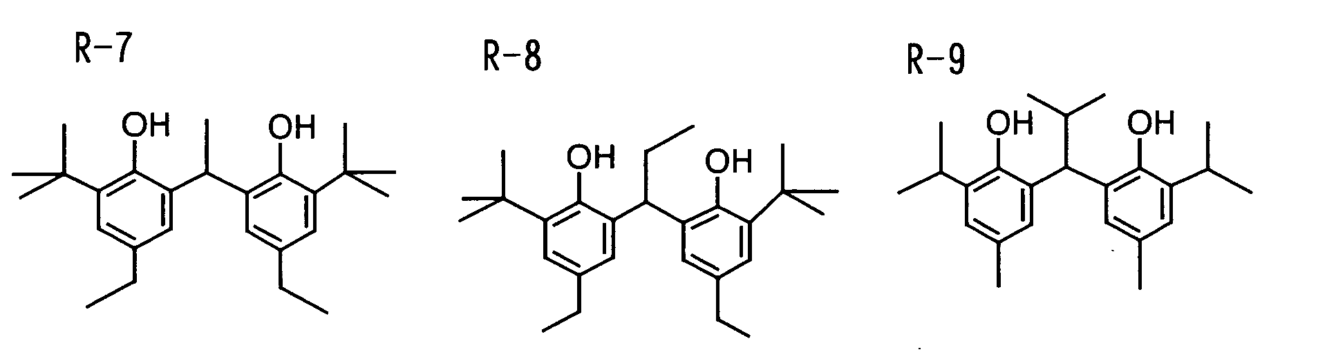


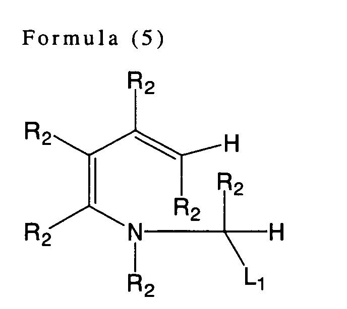


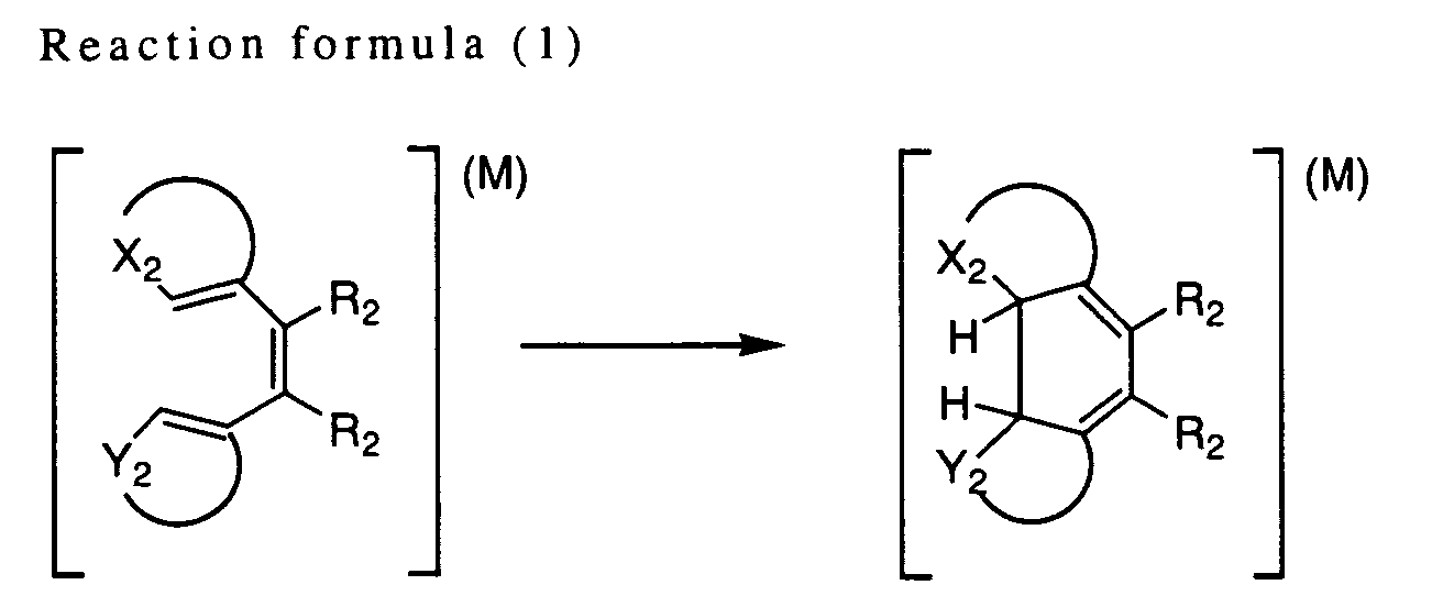

X-L2-Y


A-(W)n-B


Q1-NHNH-Q2


Q-(Y)n-C(Z1)(Z2)X


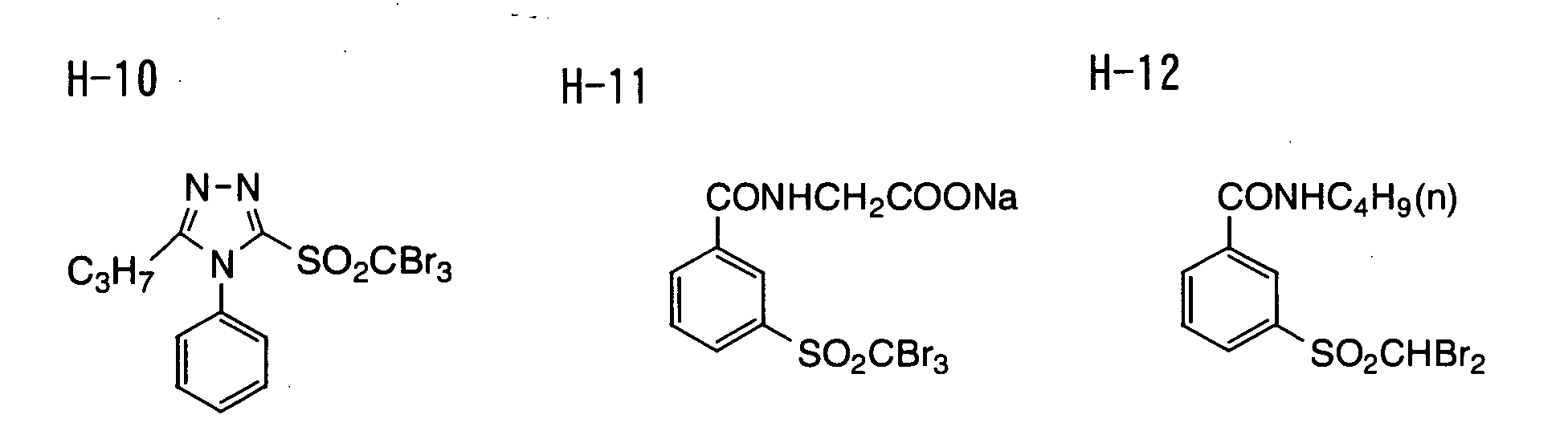


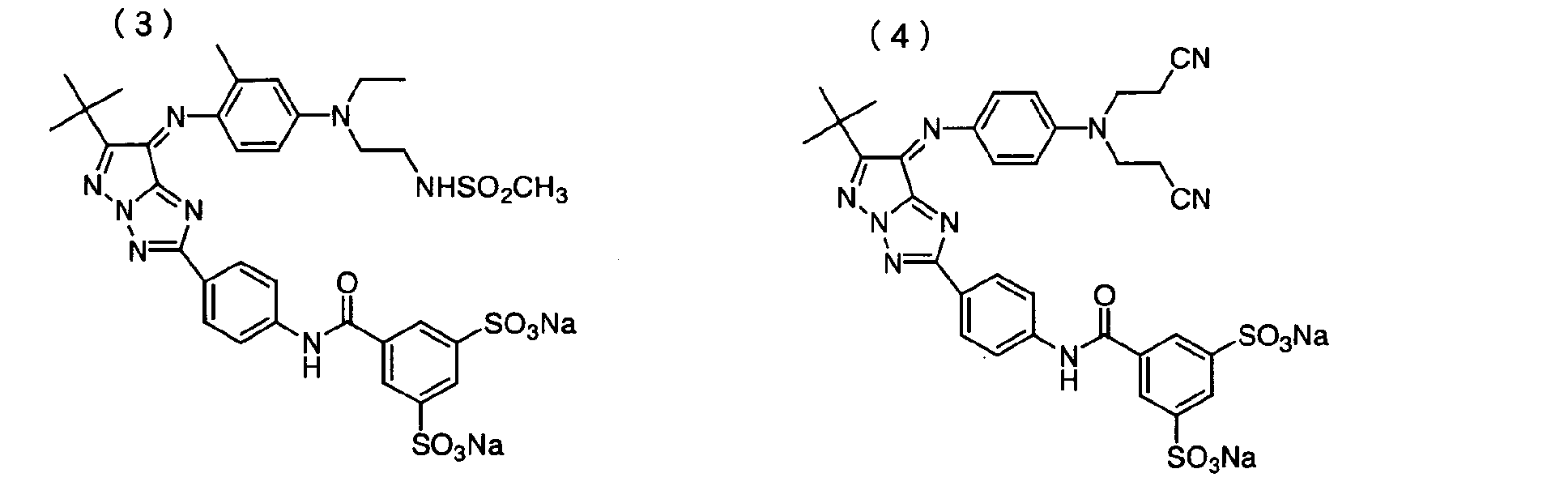


| Formula (1) (for undercoat layer on the image forming layer side) | |
| Pesresin A-520 manufactured by Takamatsu Oil & Fat Co., Ltd. (30% by weight solution) | 59 g |
| Polyethyleneglycol monononylphenylether (average ethylene oxide number = 8.5) 10% by weight solution | 5.4 g |
| MP-1000 manufactured by Soken Chemical & Engineering Co., Ltd. (polymer fine particle, mean particle diameter of 0.4 µm) | 0.91 g |
| Distilled water | 935 mL |
| Formula (2) (for first layer on the backside) | |
| Styrene-butadiene copolymer latex (solid content of 40% by weight, styrene/butadiene weight ratio = 68/32) | 158 g |
| Sodium salt of 2,4-dichloro-6-hydroxy-S-triazine (8% by weight aqueous solution) | 20 g |
| 1% by weight aqueous solution of sodium laurylbenzenesulfonate | 10 mL |
| Distilled water | 854 mL |
| Formula (3) (for second layer on the backside) | |
| SnO2/SbO (9/1 weight ratio, mean particle diameter of 0.038 µm, 17% by weight dispersion) | 84 g |
| Gelatin (10% by weight aqueous solution) | 89.2 g |
| METOLOSE TC-5 manufactured by Shin-Etsu Chemical Co., Ltd. (2% by weight aqueous solution) | 8.6 g |
| MP-1000 manufactured by Soken Chemical & Engineering Co., Ltd. | 0.01 g |
| 1% by weight aqueous solution of sodium dodecylbenzenesulfonate | 10 mL |
| NaOH (1 % by weight) | 6 mL |
| Proxel (manufactured by Imperial Chemical Industries PLC) | 1 mL |
| Distilled water | 805 mL |

| Silver salt of fatty acid | 5.42 |
| Pigment-1 (C. I. Pigment Blue 60) | 0.036 |
| Organic polyhalogen compound-1 | 0.12 |
| Organic polyhalogen compound-2 | 0.25 |
| Phthalazine compound-1 | 0.18 |
| SBR latex | 9.70 |
| Reducing agent-1 | 0.40 |
| Reducing agent-2 | 0.40 |
| Hydrogen bonding compound-1 | 0.58 |
| Development accelerator-1 | 0.019 |
| Development accelerator-2 | 0.016 |
| Mercapto compound-1 | 0.002 |
| Mercapto compound-2 | 0.012 |
| Silver halide (on the basis of Ag content) | 0.10 |


| Sample No. | Magenta Dye | Hue Angle Difference | Diagnostic Ability | Fog | Sensitivity | Sharpness | Note |
| 102 | - | - | 4 | 0.17 | 100 | 93 | Invention |
| 501 | Formula( I )-(1) | 90 | 5 | 0.17 | 100 | 93 | Invention |
| 502 | Formula( I )-(3) | 90 | 5 | 0.17 | 100 | 93 | Invention |
| 503 | Formula( I )-(4) | 120 | 5 | 0.18 | 95 | 94 | Invention |
| 504 | Formula( I )-(34) | 60 | 5 | 0.17 | 100 | 91 | Invention |

Claims (20)
- A silver halide photosensitive material comprising a phthalocyanine compound represented by the following formula (PC-1):wherein, M represents a hydrogen atom or a metal atom; R1, R4, R5, R8, R9, R12, R13, and R16 each independently represent a hydrogen atom or a substituent; at least one of R1, R4, R5, R8, R9, R12, R13, and R16 represents an electron-attracting group; and R2, R3, R6, R7, R10, R11, R14, and R15 each independently represent a hydrogen atom or a substituent.

- The silver halide photosensitive material according to claim 1, wherein at least one of R1, R4, R5, R8, R9, R12, R13, and R16 of the phthalocyanine compound represented by formula (PC-1) is a group represented by the following formula (II):
-L1-R17 - The silver halide photosensitive material according to claim 2, wherein 4 or more of R1, R4, R5, R8, R9, R12, R13, and R16 of the phthalocyanine compound represented by formula (PC-1) are a group represented by formula (II).
- The silver halide photosensitive material according to claim 1, wherein the phthalocyanine compound represented by formula (PC-1) is soluble in water.
- The silver halide photosensitive material according to claim 1, wherein the phthalocyanine compound has an absorption maximum within a range of 620 nm to 700 nm.
- A photothermographic material having, on at least one side of a support, an image forming layer comprising at least a photosensitive silver halide, a non-photosensitive organic silver salt, and a reducing agent for the organic silver salt and at least one non-photosensitive layer, wherein the photothermographic material contains a phthalocyanine compound represented by the following formula (PC-1):wherein in formula (PC-1), M represents a hydrogen atom or a metal atom; R1, R4, R5, R8, R9, R12, R13, and R16 each independently represent a hydrogen atom or a substituent; at least one of R1, R4, R5, R8, R9, R12, R13, and R16 represents an electron-attracting group; and R2, R3, R6, R7, R10, R11, R14, and R15 each independently represent a hydrogen atom or a substituent.

- The photothermographic material according to claim 6, wherein at least one of R1, R4, R5, R8, R9, R12, R13, and R16 of the phthalocyanine compound represented by formula (PC-1) is a group represented by the following formula (II):
-L1-R17 - The photothermographic material according to claim 7, wherein 4 or more of R1, R4, R5, R8, R9, R12, R13, and R16 of the phthalocyanine compound represented by formula (PC-1) are a group represented by formula (II).
- The photothermographic material according to claim 6, wherein the phthalocyanine compound represented by formula (PC-1) is soluble in water.
- The photothermographic material according to claim 6, wherein the phthalocyanine compound has an absorption maximum within a range of 620 nm to 700 nm.
- The photothermographic material according to claim 10, wherein a ratio of a light absorption density at 610 nm to a light absorption density at an exposure wavelength after the thermal development is in a range from 0.2 to 0.8.
- The photothermographic material according to claim 6, wherein the phthalocyanine compound is contained in the image forming layer.
- The photothermographic material according to claim 6, wherein the phthalocyanine compound is contained in a non-photosensitive layer.
- The photothermographic material according to claim 13, wherein the non-photosensitive layer is a back layer.
- The photothermographic material according to claim 13, wherein the non-photosensitive layer is provided between the support and the image forming layer.
- The photothermographic material according to claim 13, wherein the non-photosensitive layer is provided on the image forming layer at an upper layer with respect to the support.
- The photothermographic material according to claim 16, wherein the photothermographic material has an outermost layer on the image forming layer at an upper layer with respect to the support, and the non-photosensitive layer is provided between the outermost layer and the image forming layer.
- The photothermographic material according to claim 6, further comprising a magenta dye.
- The photothermographic material according to claim 18, wherein the magenta dye is contained in the same layer with the phthalocyanine compound.
- The photothermographic material according to claim 18, wherein a difference in hue angle between the phthalocyanine compound and the magenta dye is 70° to 110°.
Applications Claiming Priority (8)
| Application Number | Priority Date | Filing Date | Title |
|---|---|---|---|
| JP2004085655 | 2004-03-23 | ||
| JP2004085655 | 2004-03-23 | ||
| JP2004244080 | 2004-08-24 | ||
| JP2004244080 | 2004-08-24 | ||
| JP2004315901 | 2004-10-29 | ||
| JP2004315901 | 2004-10-29 | ||
| JP2005025698 | 2005-02-01 | ||
| JP2005025698A JP4369876B2 (en) | 2004-03-23 | 2005-02-01 | Silver halide photosensitive material and photothermographic material |
Publications (2)
| Publication Number | Publication Date |
|---|---|
| EP1582919A1 true EP1582919A1 (en) | 2005-10-05 |
| EP1582919B1 EP1582919B1 (en) | 2014-07-16 |
Family
ID=34891238
Family Applications (1)
| Application Number | Title | Priority Date | Filing Date |
|---|---|---|---|
| EP05005950.0A Active EP1582919B1 (en) | 2004-03-23 | 2005-03-18 | Photothermographic material |
Country Status (3)
| Country | Link |
|---|---|
| US (1) | US7157220B2 (en) |
| EP (1) | EP1582919B1 (en) |
| JP (1) | JP4369876B2 (en) |
Cited By (3)
| Publication number | Priority date | Publication date | Assignee | Title |
|---|---|---|---|---|
| EP1635216A1 (en) * | 2004-09-14 | 2006-03-15 | Fuji Photo Film Co., Ltd. | Photothermographic material |
| EP1840646A1 (en) * | 2006-03-27 | 2007-10-03 | FUJIFILM Corporation | Photothermographic material |
| CN104045644A (en) * | 2013-03-14 | 2014-09-17 | 富士胶片株式会社 | Manufacturing Method Of Metal Phthalocyanine Compound And Metal Phthalocyanine Compound |
Families Citing this family (9)
| Publication number | Priority date | Publication date | Assignee | Title |
|---|---|---|---|---|
| JP2006084870A (en) * | 2004-09-16 | 2006-03-30 | Fuji Photo Film Co Ltd | Heat developable sensitive material |
| US7332267B2 (en) * | 2002-12-17 | 2008-02-19 | Fujifilm Corporation | Photothermographic material |
| US7553960B2 (en) * | 2004-03-23 | 2009-06-30 | Fujifilm Corporation | Phthalocyanine compound |
| US7226728B2 (en) * | 2004-09-24 | 2007-06-05 | Fujifilm Corporation | Photothermographic material |
| US7303865B2 (en) * | 2004-11-26 | 2007-12-04 | Fujifilm Corporation | Photothermographic material |
| US7291448B2 (en) * | 2005-02-24 | 2007-11-06 | Fujifilm Corporation | Photothermographic material |
| JP2007233097A (en) * | 2006-03-01 | 2007-09-13 | Fujifilm Corp | Heat developable photosensitive material |
| WO2016160703A1 (en) | 2015-03-27 | 2016-10-06 | Harrup Mason K | All-inorganic solvents for electrolytes |
| US10707531B1 (en) | 2016-09-27 | 2020-07-07 | New Dominion Enterprises Inc. | All-inorganic solvents for electrolytes |
Citations (283)
| Publication number | Priority date | Publication date | Assignee | Title |
|---|---|---|---|---|
| US2681294A (en) | 1951-08-23 | 1954-06-15 | Eastman Kodak Co | Method of coating strip material |
| US2761791A (en) | 1955-02-23 | 1956-09-04 | Eastman Kodak Co | Method of multiple coating |
| GB837095A (en) | 1957-12-16 | 1960-06-09 | Ilford Ltd | Improvements in or relating to the production of multilayer photographic materials |
| US3061432A (en) | 1958-06-21 | 1962-10-30 | Agfa Ag | Pyrazolino benzimidazole color coupler |
| GB1226562A (en) * | 1968-03-25 | 1971-03-31 | ||
| US3700458A (en) | 1971-03-01 | 1972-10-24 | Eastman Kodak Co | Chemical process |
| US3725067A (en) | 1970-01-15 | 1973-04-03 | Eastman Kodak Co | Silver halide emulsion containing 1-h-pyrazolo(3,2-c)-s-triazole color couplers |
| JPS4855730A (en) | 1971-11-05 | 1973-08-04 | ||
| US3871887A (en) | 1974-01-02 | 1975-03-18 | Eastman Kodak Co | Photothermographic composition, element and process |
| US3874946A (en) | 1974-02-19 | 1975-04-01 | Eastman Kodak Co | Photothermographic element, composition and process |
| US3877943A (en) | 1973-02-06 | 1975-04-15 | Fuji Photo Film Co Ltd | Heat developable photographic material |
| JPS5073627A (en) | 1973-09-06 | 1975-06-17 | Agfa Gevaert Nv | |
| JPS5089020A (en) | 1973-12-05 | 1975-07-17 | ||
| JPS50119624A (en) | 1974-02-19 | 1975-09-19 | ||
| JPS50137126A (en) | 1974-04-16 | 1975-10-31 | ||
| JPS53106125A (en) | 1977-02-28 | 1978-09-14 | Fuji Photo Film Co Ltd | Dyestuff image recording |
| JPS5430032A (en) | 1977-08-10 | 1979-03-06 | Fuji Photo Film Co Ltd | Treatment of photosensitive mathrial of heat-development type |
| JPS5512581B2 (en) | 1973-12-21 | 1980-04-02 | ||
| JPS55118034A (en) | 1979-03-05 | 1980-09-10 | Fuji Photo Film Co Ltd | Color image forming method |
| JPS5662648A (en) | 1979-10-29 | 1981-05-28 | Hitachi Metals Ltd | Metal mold for prevention of camber |
| US4281060A (en) | 1979-06-27 | 1981-07-28 | Fuji Photo Film Co., Ltd. | Heat-developable photosensitive materials |
| JPS56120519A (en) | 1980-02-21 | 1981-09-21 | Fuji Photo Film Co Ltd | Needlelike tin oxide and its manufacture |
| JPS56143430A (en) | 1980-04-11 | 1981-11-09 | Fuji Photo Film Co Ltd | Photographic sensitive material with improved antistatic property |
| JPS56143431A (en) | 1980-04-11 | 1981-11-09 | Fuji Photo Film Co Ltd | Photographic sensitive material with improved antistatic property |
| JPS57119341A (en) | 1981-01-16 | 1982-07-24 | Fuji Photo Film Co Ltd | Photosensitive material for heat development |
| JPS57150841A (en) | 1981-03-13 | 1982-09-17 | Konishiroku Photo Ind Co Ltd | Silver halide photosensitive material |
| US4351897A (en) | 1980-08-12 | 1982-09-28 | Fuji Photo Film Co., Ltd. | Color photographic light-sensitive material |
| EP0073636A1 (en) | 1981-08-25 | 1983-03-09 | EASTMAN KODAK COMPANY (a New Jersey corporation) | Photographic elements containing ballasted couplers |
| JPS5862644A (en) | 1981-10-09 | 1983-04-14 | Fuji Photo Film Co Ltd | Photographic support |
| JPS5862646A (en) | 1981-10-09 | 1983-04-14 | Fuji Photo Film Co Ltd | Antistaticized silver halide photosensitive material |
| JPS5948753A (en) | 1982-07-29 | 1984-03-21 | ミネソタ・マイニング・アンド・マニユフアクチユアリング・コンパニ− | Photothermo-graphic material spectrally sensitized and manufacture thereof |
| JPS5957234A (en) | 1982-09-27 | 1984-04-02 | Fuji Photo Film Co Ltd | Thermodevelopable photosensitive material |
| US4460681A (en) | 1983-03-15 | 1984-07-17 | Minnesota Mining And Manufacturing Company | Image enhancement of photothermographic elements |
| JPS59193447A (en) | 1983-04-18 | 1984-11-02 | Fuji Photo Film Co Ltd | Photosensitive silver halide material for daylight room |
| US4500630A (en) | 1983-02-15 | 1985-02-19 | Fuji Photo Film Co., Ltd. | Method for forming magenta color image |
| JPS6033552A (en) | 1983-08-04 | 1985-02-20 | Fuji Photo Film Co Ltd | Color image forming method |
| JPS6035730A (en) | 1983-08-08 | 1985-02-23 | Fuji Photo Film Co Ltd | Color photographic sensitive silver halide material |
| JPS6043659A (en) | 1983-08-19 | 1985-03-08 | Fuji Photo Film Co Ltd | Formation of color image |
| JPS60153039A (en) | 1984-01-20 | 1985-08-12 | Fuji Photo Film Co Ltd | Photosensitive silver halide material |
| US4540654A (en) | 1983-03-18 | 1985-09-10 | Fuji Photo Film Co., Ltd. | Method of forming color image comprising heterocyclic magenta dye-forming coupler |
| JPS60185951A (en) | 1984-02-07 | 1985-09-21 | Fuji Photo Film Co Ltd | Silver halide color photosensitive material |
| US4556630A (en) | 1983-06-20 | 1985-12-03 | Fuji Photo Film Co., Ltd. | Color photographic light-sensitive material |
| JPS6172238A (en) | 1984-09-14 | 1986-04-14 | Konishiroku Photo Ind Co Ltd | Silver halide color photosensitive material |
| JPS6289048A (en) | 1985-10-16 | 1987-04-23 | Fuji Photo Film Co Ltd | Formation of picture image |
| JPS62210458A (en) | 1986-03-11 | 1987-09-16 | Fuji Photo Film Co Ltd | Image forming method |
| US4708928A (en) | 1986-08-29 | 1987-11-24 | Minnesota Mining And Manufacturing Company | Photothermographic element comprising particles each containing silver halide, a silver compound and reducing agent |
| JPS63103235A (en) | 1986-10-20 | 1988-05-07 | Fuji Photo Film Co Ltd | Negative image forming method |
| JPS63104046A (en) | 1986-10-21 | 1988-05-09 | Fuji Photo Film Co Ltd | Daylight silver halide photographic sensitive material |
| JPS63145281A (en) | 1986-12-09 | 1988-06-17 | Fuji Photo Film Co Ltd | Pyrazoloazoleazomethyne dye |
| WO1988004795A1 (en) | 1986-12-22 | 1988-06-30 | Eastman Kodak Company | Photographic silver halide element and process |
| US4756999A (en) | 1985-11-20 | 1988-07-12 | Minnesota Mining And Manufacturing Company | Photothermographic materials |
| JPS63208846A (en) | 1987-02-26 | 1988-08-30 | Fuji Photo Film Co Ltd | Silver halide photographic sensitive material |
| EP0293917A2 (en) | 1987-06-05 | 1988-12-07 | Fuji Photo Film Co., Ltd. | Color photographic light-sensitive material and method of developing the same |
| US4791042A (en) | 1985-10-18 | 1988-12-13 | Fuji Photo Film Co., Ltd. | Epoxy hardener in dye fixing element |
| JPS63306436A (en) | 1987-06-08 | 1988-12-14 | Konica Corp | Negative type silver halide photographic sensitive material handleable in daylight room and having satisfactory return characteristic |
| JPS63314535A (en) | 1987-06-17 | 1988-12-22 | Konica Corp | Silver halide photographic sensitive material for light room |
| JPS6461745A (en) | 1987-09-01 | 1989-03-08 | Fuji Photo Film Co Ltd | Silver halide photographic sensitive material |
| JPH01100530A (en) | 1987-10-13 | 1989-04-18 | Konica Corp | Silver halide photographic sensitive material |
| US4873184A (en) | 1988-02-05 | 1989-10-10 | Minnesota Mining And Manufacturing Company | Supersensitization of silver halide photothermographic emulsions |
| JPH0296131A (en) | 1988-06-23 | 1990-04-06 | Asahi Chem Ind Co Ltd | Dye aggregate-containing composition |
| JPH02252578A (en) | 1989-03-27 | 1990-10-11 | Fuji Photo Film Co Ltd | Thermally transferable image recording |
| JPH037386A (en) | 1989-03-30 | 1991-01-14 | Fuji Photo Film Co Ltd | Thermally transferable color-donative material |
| JPH0339737A (en) | 1989-07-06 | 1991-02-20 | Fuji Photo Film Co Ltd | Processing method for silver halide color photographic sensitive material |
| JPH03244593A (en) | 1990-02-23 | 1991-10-31 | Fuji Photo Film Co Ltd | Thermal transfer color-donative material |
| EP0456257A1 (en) | 1990-05-10 | 1991-11-13 | Fuji Photo Film Co., Ltd. | Silver halide color photographic material |
| JPH04126772A (en) | 1990-09-17 | 1992-04-27 | Fuji Photo Film Co Ltd | Production of azomethine or indoaniline dyestuff |
| EP0486965A1 (en) | 1990-11-17 | 1992-05-27 | Fuji Photo Film Co., Ltd. | Silver halide color photographic materials |
| US5135842A (en) | 1989-06-12 | 1992-08-04 | Minnesota Mining And Manufacturing Company | Thermal dye bleach construction |
| JPH04247449A (en) | 1991-02-01 | 1992-09-03 | Fuji Photo Film Co Ltd | Silver halide photographic sensitive material |
| JPH04359967A (en) | 1991-06-07 | 1992-12-14 | Fuji Photo Film Co Ltd | Pyrrolotriazole azomethine color |
| JPH04359968A (en) | 1991-06-07 | 1992-12-14 | Fuji Photo Film Co Ltd | Pyrrolotrizole azomethine color |
| JPH05204106A (en) | 1992-01-29 | 1993-08-13 | Fuji Photo Film Co Ltd | Silver halide color photographic sensitive material and photographic pyrazolotriazole type coupler |
| JPH05313284A (en) | 1992-05-14 | 1993-11-26 | Fuji Photo Film Co Ltd | Silver halide photographic sensitive material |
| EP0571959A2 (en) | 1992-05-26 | 1993-12-01 | Fuji Photo Film Co., Ltd. | Photographic coupler and silver halide color photographic material |
| JPH05341432A (en) | 1992-03-06 | 1993-12-24 | Minnesota Mining & Mfg Co <3M> | Thermooptical photographic element |
| JPH0611791A (en) | 1991-06-28 | 1994-01-21 | Fuji Photo Film Co Ltd | Silver halide photographic sensitive material |
| EP0587338A2 (en) | 1992-09-02 | 1994-03-16 | Minnesota Mining And Manufacturing Company | Silver halide imaging materials |
| US5314795A (en) | 1992-12-21 | 1994-05-24 | Minnesota Mining And Manufacturing Company | Thermal-dye-bleach construction comprising a polymethine dye and a thermal carbanion-generating agent |
| US5324627A (en) | 1992-12-21 | 1994-06-28 | Minnesota Mining And Manufacturing Company | Tetra-alkylammonium phenylsulfonylacetate thermal-dye-bleach agents |
| JPH06208193A (en) | 1992-11-30 | 1994-07-26 | Minnesota Mining & Mfg Co <3M> | Photothermal photographic element |
| US5340712A (en) | 1993-04-21 | 1994-08-23 | Minnesota Mining And Manufacturing Company | Antifoggants for photothermographic articles |
| US5369000A (en) | 1993-04-29 | 1994-11-29 | Minnesota Mining And Manufacturing Company | Post-processing stabilizers for photothermographic articles |
| JPH072781A (en) | 1993-06-08 | 1995-01-06 | Minnesota Mining & Mfg Co <3M> | Photothermal photographic material |
| JPH075621A (en) | 1993-01-06 | 1995-01-10 | Minnesota Mining & Mfg Co <3M> | Optothermographic material |
| JPH07128768A (en) | 1993-10-29 | 1995-05-19 | Fuji Photo Film Co Ltd | Silver halide photographic sensitive material |
| EP0655645A1 (en) * | 1993-11-29 | 1995-05-31 | Minnesota Mining And Manufacturing Company | Silver halide photographic material with reduced fog and improved residual stain |
| JPH07225449A (en) | 1994-02-16 | 1995-08-22 | Fuji Photo Film Co Ltd | Silver halide image forming material |
| JPH0794180B2 (en) | 1987-09-03 | 1995-10-11 | 富士写真フイルム株式会社 | Thermal transfer material |
| US5510236A (en) | 1995-05-12 | 1996-04-23 | Eastman Kodak Company | Spectrally sensitized photothermographic elements |
| JPH08240877A (en) | 1995-03-03 | 1996-09-17 | Fuji Photo Film Co Ltd | Silver halide photographic sensitive material and processing method therefor |
| JPH08254793A (en) | 1995-03-17 | 1996-10-01 | Fuji Photo Film Co Ltd | Packaging material for photosensitive material and photosensitive material packaged with same |
| US5575957A (en) | 1994-12-27 | 1996-11-19 | Ishihara Sangyo Kaisha, Ltd. | Acicular electroconductive tin oxide fine particles and process for producing same |
| JPH0943766A (en) | 1995-05-24 | 1997-02-14 | Fuji Photo Film Co Ltd | Infrared ray sensitive heat-developable photosensitive material and its manufacture |
| JPH09146220A (en) | 1995-11-17 | 1997-06-06 | Fuji Photo Film Co Ltd | Silver halide photographic sensitive material and position detecting method therefor |
| JPH09160164A (en) | 1995-12-06 | 1997-06-20 | Fuji Photo Film Co Ltd | Heat-developable photosensitive material |
| JPH09160167A (en) | 1995-12-04 | 1997-06-20 | Fuji Photo Film Co Ltd | Silver halide photosensitive material |
| EP0786692A1 (en) | 1996-01-26 | 1997-07-30 | Eastman Kodak Company | Silver halide light sensitive emulsion layer having enhanced photographic sensitivity |
| JPH09211769A (en) | 1996-01-26 | 1997-08-15 | Eastman Kodak Co | Photographic element |
| JPH09211774A (en) | 1996-01-26 | 1997-08-15 | Eastman Kodak Co | Photographic element |
| JPH09230531A (en) | 1996-02-23 | 1997-09-05 | Fuji Photo Film Co Ltd | Heat developable photosensitive material |
| JPH09244177A (en) | 1996-03-05 | 1997-09-19 | Fuji Photo Film Co Ltd | Novel polyhalomethane compound and photosensitive material containing the same |
| JPH09244178A (en) | 1996-03-05 | 1997-09-19 | Fuji Photo Film Co Ltd | Heat developable photosensitive material |
| JPH09258367A (en) | 1996-03-26 | 1997-10-03 | Fuji Photo Film Co Ltd | Novel polyhalomethane compound and photosensitive material |
| JPH09265150A (en) | 1996-03-28 | 1997-10-07 | Fuji Photo Film Co Ltd | Heat developable photosensitive material |
| EP0803763A1 (en) | 1996-04-22 | 1997-10-29 | Agfa-Gevaert N.V. | A cassette for photo-stimulable radiography |
| EP0803764A1 (en) | 1996-04-26 | 1997-10-29 | Fuji Photo Film Co., Ltd. | Photothermographic material and method for making |
| JPH09281637A (en) | 1996-04-19 | 1997-10-31 | Fuji Photo Film Co Ltd | Heat-developable photosensitive material |
| JPH09281636A (en) | 1996-04-15 | 1997-10-31 | Fuji Photo Film Co Ltd | Heat-developable photosensitive material |
| JPH09297367A (en) | 1996-05-07 | 1997-11-18 | Fuji Photo Film Co Ltd | Heat-developable photosensitive material |
| JPH09304869A (en) | 1996-05-10 | 1997-11-28 | Fuji Photo Film Co Ltd | Heat developable photosensitive material |
| JPH09304875A (en) | 1996-05-17 | 1997-11-28 | Fuji Photo Film Co Ltd | Heat developable photosensitive material |
| JPH09311405A (en) | 1996-05-23 | 1997-12-02 | Fuji Photo Film Co Ltd | Heat developing material |
| JPH09319022A (en) | 1996-03-28 | 1997-12-12 | Fuji Photo Film Co Ltd | New polyhalomethane compound and photosensitive material |
| JPH09329865A (en) | 1996-06-12 | 1997-12-22 | Fuji Photo Film Co Ltd | Heat developable photosensitive material |
| JPH1010669A (en) | 1996-04-26 | 1998-01-16 | Fuji Photo Film Co Ltd | Manufacture of heat-developable photosensitive material |
| JPH1018568A (en) | 1996-07-05 | 1998-01-20 | Toyox Co Ltd | Floor heating panel or heating tatami mat |
| JPH1036695A (en) | 1996-07-18 | 1998-02-10 | Fuji Photo Film Co Ltd | Dihydroperimidinesquarylium dye and recording material containing the same |
| JPH1062899A (en) | 1996-08-16 | 1998-03-06 | Fuji Photo Film Co Ltd | Heat-developable photosensitive material |
| JPH1062895A (en) | 1996-08-16 | 1998-03-06 | Fuji Photo Film Co Ltd | Silver halide photographic sensitive material and image forming method |
| JPH1069023A (en) | 1996-06-18 | 1998-03-10 | Fuji Photo Film Co Ltd | Heat-developable photosensitive material |
| JPH1090823A (en) | 1996-09-12 | 1998-04-10 | Fuji Photo Film Co Ltd | Silver halide photographic sensitive material |
| JPH10104779A (en) | 1996-10-03 | 1998-04-24 | Fuji Photo Film Co Ltd | Recording material containing squalilium dye |
| JPH10111543A (en) | 1996-07-24 | 1998-04-28 | Agfa Gevaert Nv | Photothermographic material containing at least one kind of dye absorbing electromagnetic beam in wavelength range of 700-1,100nm |
| JPH10171063A (en) | 1996-12-06 | 1998-06-26 | Fuji Photo Film Co Ltd | Sliver halide photographic sensitive material, and novel polyhalogen compound |
| JPH10186565A (en) | 1996-12-25 | 1998-07-14 | Fuji Photo Film Co Ltd | Heat-developable photosensitive material |
| JPH10186567A (en) | 1996-12-25 | 1998-07-14 | Fuji Photo Film Co Ltd | Heat-developable photosensitive material |
| JPH10186569A (en) | 1996-12-25 | 1998-07-14 | Fuji Photo Film Co Ltd | Heat-developable photosensitive material |
| JPH10186572A (en) | 1996-12-26 | 1998-07-14 | Fuji Photo Film Co Ltd | Heat-developable photosensitive material |
| JPH10186568A (en) | 1996-12-25 | 1998-07-14 | Fuji Photo Film Co Ltd | Heat-developable photosensitive material |
| JPH10197988A (en) | 1996-12-28 | 1998-07-31 | Fuji Photo Film Co Ltd | Heat-developable photosensitive material |
| JPH10197985A (en) | 1996-12-28 | 1998-07-31 | Fuji Photo Film Co Ltd | Heat-developable photosensitive material |
| JPH10197983A (en) | 1996-12-27 | 1998-07-31 | Fuji Photo Film Co Ltd | Heat developable photosensitive material |
| JPH10197982A (en) | 1996-12-27 | 1998-07-31 | Fuji Photo Film Co Ltd | Heat-developable photosensitive material |
| JPH10197974A (en) | 1997-01-10 | 1998-07-31 | Fuji Photo Film Co Ltd | Photographic sensitive material |
| JPH10197987A (en) | 1997-01-14 | 1998-07-31 | Fuji Photo Film Co Ltd | Heat-developable material |
| JPH10197989A (en) | 1997-01-10 | 1998-07-31 | Fuji Photo Film Co Ltd | Heat-developable photosensitive material |
| JPH10207001A (en) | 1997-01-24 | 1998-08-07 | Fuji Photo Film Co Ltd | Heat developable material |
| JPH10207004A (en) | 1997-01-23 | 1998-08-07 | Fuji Photo Film Co Ltd | Heat-developable photosensitive material |
| WO1998036322A1 (en) | 1997-02-17 | 1998-08-20 | Fuji Photo Film Co., Ltd. | Heat developing photosensitive recording material |
| JPH10221807A (en) | 1997-02-05 | 1998-08-21 | Fuji Photo Film Co Ltd | Heat-developable material |
| JPH10268465A (en) | 1997-03-27 | 1998-10-09 | Fuji Photo Film Co Ltd | Heat-developable photosensitive material |
| JPH10282601A (en) | 1997-04-01 | 1998-10-23 | Fuji Photo Film Co Ltd | Heat-developable photosensitive material |
| JPH10288823A (en) | 1997-04-16 | 1998-10-27 | Fuji Photo Film Co Ltd | Image forming material |
| JPH10288824A (en) | 1997-04-16 | 1998-10-27 | Fuji Photo Film Co Ltd | Image forming material |
| JPH10307365A (en) | 1997-05-09 | 1998-11-17 | Fuji Photo Film Co Ltd | Heat developing image forming material |
| JPH10312038A (en) | 1997-05-12 | 1998-11-24 | Fuji Photo Film Co Ltd | Heat-developable photosensitive material |
| EP0883022A1 (en) | 1997-06-06 | 1998-12-09 | Fuji Photo Film Co., Ltd. | Coating method for thermographic imaging element, coating solution for thermographic image forming layer, thermographic imaging element, and photothermographic imaging element |
| JPH10339934A (en) | 1997-06-06 | 1998-12-22 | Fuji Photo Film Co Ltd | Image recording material |
| US5858637A (en) | 1997-06-27 | 1999-01-12 | Eastman Kodak Company | Process of preparing a photothermographic composition of enhanced photosensitivity |
| JPH117100A (en) | 1997-06-16 | 1999-01-12 | Fuji Photo Film Co Ltd | Heat-developable image recording material |
| JPH116872A (en) | 1997-06-18 | 1999-01-12 | Honda Motor Co Ltd | Fm-cw radar device |
| JPH1115105A (en) | 1997-06-26 | 1999-01-22 | Fuji Photo Film Co Ltd | Production of coating liquid for photosensitive image forming medium and heat developing photosensitive material |
| JPH1115116A (en) | 1997-06-19 | 1999-01-22 | Fuji Photo Film Co Ltd | Silver halide color photographic sensitive material and image forming method by using the same |
| EP0893732A1 (en) | 1997-07-25 | 1999-01-27 | Eastman Kodak Company | Silver halide light sensitive emulsion layer having enhanced photographic sensitivity |
| EP0893731A1 (en) | 1997-07-25 | 1999-01-27 | Eastman Kodak Company | Silver halide light sensitive emulsion layer having enhanced photographic sensitivity |
| JPH1124201A (en) | 1997-07-01 | 1999-01-29 | Fuji Photo Film Co Ltd | Heat-developable photosensitive material |
| JPH1124200A (en) | 1997-06-30 | 1999-01-29 | Fuji Photo Film Co Ltd | Heat-developable photosensitive material |
| JPH1130832A (en) | 1997-07-11 | 1999-02-02 | Fuji Photo Film Co Ltd | Heat-developable photographic material |
| JPH1165021A (en) | 1997-08-14 | 1999-03-05 | Fuji Photo Film Co Ltd | Sensitive heat development image recording material |
| JPH1184573A (en) | 1997-09-09 | 1999-03-26 | Fuji Photo Film Co Ltd | Heat developable image recording material |
| JPH1184574A (en) | 1997-09-02 | 1999-03-26 | Fuji Photo Film Co Ltd | Heat developable recording material |
| JPH1191652A (en) | 1997-09-26 | 1999-04-06 | Yokohama Rubber Co Ltd:The | Endless track belt and its manufacture |
| JPH11106881A (en) | 1997-09-30 | 1999-04-20 | Nisshin Steel Co Ltd | Device for cooling plated steel sheet in continuous hot dip aluminum coating line |
| JPH11109547A (en) | 1997-10-03 | 1999-04-23 | Fuji Photo Film Co Ltd | Heat developable photosensitive material |
| JPH11119374A (en) | 1997-10-13 | 1999-04-30 | Fuji Photo Film Co Ltd | Heat developable photosensitive material |
| JPH11125880A (en) | 1997-10-23 | 1999-05-11 | Fuji Photo Film Co Ltd | Production of thermal image forming material |
| JPH11129629A (en) | 1997-10-27 | 1999-05-18 | Fuji Photo Film Co Ltd | Recording material and its production |
| JPH11133542A (en) | 1997-10-24 | 1999-05-21 | Fuji Photo Film Co Ltd | Heat-developable photosensitive material for exposure to laser beams |
| JPH11133536A (en) | 1997-10-28 | 1999-05-21 | Fuji Photo Film Co Ltd | Heat developable photosensitive material |
| JPH11133572A (en) | 1997-08-26 | 1999-05-21 | Fuji Photo Film Co Ltd | Thermal processor and thermal developing device using it |
| JPH11133539A (en) | 1997-10-27 | 1999-05-21 | Fuji Photo Film Co Ltd | Heat developable photosensitive material |
| JPH11133543A (en) | 1997-10-27 | 1999-05-21 | Fuji Photo Film Co Ltd | Manufacture of heat image-forming material |
| JPH11223898A (en) | 1998-02-06 | 1999-08-17 | Fuji Photo Film Co Ltd | Heat developable photosensitive material |
| JPH11228698A (en) | 1998-02-09 | 1999-08-24 | Catalysts & Chem Ind Co Ltd | Fine particles of organopolysiloxane, production of the same and liquid crystal display |
| JPH11231457A (en) | 1997-10-21 | 1999-08-27 | Fuji Photo Film Co Ltd | Heat developable photosensitive material, heat developed image forming method, heat dischargeable recording material, heat dischargeable image recording method and method for discharging cyanine dye |
| JPH11242304A (en) | 1998-02-26 | 1999-09-07 | Konica Corp | Heat developable photosensitive material |
| JPH11305380A (en) | 1998-04-23 | 1999-11-05 | Fuji Photo Film Co Ltd | Production of heat developable photosensitive material |
| JPH11305378A (en) | 1998-04-16 | 1999-11-05 | Fuji Photo Film Co Ltd | Heat developable photosensitive material |
| JPH11305384A (en) | 1998-04-23 | 1999-11-05 | Fuji Photo Film Co Ltd | Production of heat developable photosensitive material |
| JPH11305377A (en) | 1998-04-16 | 1999-11-05 | Fuji Photo Film Co Ltd | Heat developable photosensitive material |
| JPH11316435A (en) | 1998-04-30 | 1999-11-16 | Fuji Photo Film Co Ltd | Production of heat developing photosensitive material |
| JPH11327076A (en) | 1998-05-11 | 1999-11-26 | Fuji Photo Film Co Ltd | Heat developable photosensitive material |
| US5994051A (en) | 1997-07-25 | 1999-11-30 | Eastman Kodak Company | Silver halide light sensitive emulsion layer having enhanced photographic sensitivity |
| EP0962812A1 (en) | 1998-06-03 | 1999-12-08 | Fuji Photo Film Co., Ltd. | Aqueous dispersion of fatty acid silver salt particles, method for redispersing fatty acid silver salt particles, photothermographic light-sensitive material, and method for producing the same |
| JPH11338096A (en) | 1998-05-25 | 1999-12-10 | Fuji Photo Film Co Ltd | Heat developable photosensitive material |
| JPH11338098A (en) | 1998-05-26 | 1999-12-10 | Fuji Photo Film Co Ltd | Heat-developable photosensitive material |
| JPH11338099A (en) | 1998-05-26 | 1999-12-10 | Fuji Photo Film Co Ltd | Heat developable photosensitive material |
| JPH11343420A (en) | 1998-05-29 | 1999-12-14 | Fuji Photo Film Co Ltd | Purification of latex, latex, photosensitive material and heat-developable photosensitive material |
| JPH11349591A (en) | 1998-06-10 | 1999-12-21 | Fuji Photo Film Co Ltd | Preparation of fatty acid silber salt and thermally developable photosensitive material |
| JPH11352624A (en) | 1998-06-05 | 1999-12-24 | Fuji Photo Film Co Ltd | Image recording material |
| JPH11352627A (en) | 1998-04-07 | 1999-12-24 | Fuji Photo Film Co Ltd | Heat developable photosensitive material |
| JPH11352626A (en) | 1998-04-07 | 1999-12-24 | Fuji Photo Film Co Ltd | Heat developable photosensitive material |
| JPH11352625A (en) | 1998-04-07 | 1999-12-24 | Fuji Photo Film Co Ltd | Heat developable photosensitive material |
| EP0969313A1 (en) * | 1998-06-24 | 2000-01-05 | Eastman Kodak Company | Photothermographic element having desired color |
| JP2000002963A (en) | 1998-06-12 | 2000-01-07 | Fuji Photo Film Co Ltd | Image recording material |
| JP2000007683A (en) | 1998-06-18 | 2000-01-11 | Fuji Photo Film Co Ltd | Preparation of silver salt of fatty acid and heat developing photosensitive material |
| JP2000010229A (en) | 1998-06-18 | 2000-01-14 | Fuji Photo Film Co Ltd | Heat developing recording material |
| JP2000019680A (en) | 1998-07-06 | 2000-01-21 | Konica Corp | Heat-developable photographic sensitive material |
| JP2000019678A (en) | 1998-06-30 | 2000-01-21 | Fuji Photo Film Co Ltd | Heat developable image recording material |
| JP2000039684A (en) | 1998-07-21 | 2000-02-08 | Fuji Photo Film Co Ltd | Heat developable image recording material |
| JP2000047345A (en) | 1998-07-31 | 2000-02-18 | Fuji Photo Film Co Ltd | Production of thermal image forming material |
| JP2000072711A (en) | 1998-06-18 | 2000-03-07 | Fuji Photo Film Co Ltd | Production of nonphotosensitive fatty acid silver salt and production of heat developing photosensitive material |
| JP2000098531A (en) | 1998-09-28 | 2000-04-07 | Fuji Photo Film Co Ltd | Image forming method |
| JP2000098530A (en) | 1998-09-28 | 2000-04-07 | Fuji Photo Film Co Ltd | Production of heat developable photosensitive material |
| JP2000112060A (en) | 1998-09-30 | 2000-04-21 | Fuji Photo Film Co Ltd | Heat-developable photosensitive material, and heat developing method |
| JP2000112064A (en) | 1998-09-30 | 2000-04-21 | Fuji Photo Film Co Ltd | Heat-developable image recording material |
| JP2000112059A (en) | 1998-09-30 | 2000-04-21 | Fuji Photo Film Co Ltd | Heat-developable photosensitive material and its production |
| JP2000112070A (en) | 1998-09-30 | 2000-04-21 | Fuji Photo Film Co Ltd | Heat-developable photosensitive material |
| JP2000112104A (en) | 1998-09-30 | 2000-04-21 | Fuji Photo Film Co Ltd | Heat developing method and heat developing device |
| JP2000171936A (en) | 1998-12-03 | 2000-06-23 | Fuji Photo Film Co Ltd | Heat developable material |
| JP2000187298A (en) | 1998-12-21 | 2000-07-04 | Fuji Photo Film Co Ltd | Heat developing material |
| JP2000206653A (en) | 1998-11-13 | 2000-07-28 | Konica Corp | Heat developable photosensitive material |
| JP2000206642A (en) | 1999-01-12 | 2000-07-28 | Fuji Photo Film Co Ltd | Photosensitive heat-developable image forming material |
| JP2000214554A (en) | 1999-01-20 | 2000-08-04 | Konica Corp | Heat-developable photosensitive material and its manufacture |
| JP2000221634A (en) | 1999-02-01 | 2000-08-11 | Fuji Photo Film Co Ltd | Heat-developable sensitive material |
| JP2000267226A (en) | 1999-01-13 | 2000-09-29 | Fuji Photo Film Co Ltd | Heat developable image recording material |
| JP2000267222A (en) | 1999-03-18 | 2000-09-29 | Fuji Photo Film Co Ltd | Heat developable photosensitive material |
| JP2000284399A (en) | 1999-03-29 | 2000-10-13 | Fuji Photo Film Co Ltd | Heat developable photosensitive material |
| JP2000284410A (en) | 1999-03-30 | 2000-10-13 | Fuji Photo Film Co Ltd | Heat developable photographic material |
| JP2000284412A (en) | 1999-03-30 | 2000-10-13 | Fuji Photo Film Co Ltd | Heat developable photographic material |
| JP2000330234A (en) | 1999-03-18 | 2000-11-30 | Fuji Photo Film Co Ltd | Heat-developable recording material |
| JP2000347335A (en) | 1999-03-26 | 2000-12-15 | Fuji Photo Film Co Ltd | Silver halide emulsion, its manufacture, silver halide photographic sensitive material and heat-developable photosensitive material using same |
| JP2000356317A (en) | 1999-06-16 | 2000-12-26 | Osaka Gas Co Ltd | Long-sized burner |
| JP2001031644A (en) | 1999-07-19 | 2001-02-06 | Fuji Photo Film Co Ltd | Polyhalogenomethylsulfonyl compound |
| JP2001033907A (en) | 1999-07-16 | 2001-02-09 | Fuji Photo Film Co Ltd | Heat-developable image recording material |
| JP2001033911A (en) | 1999-07-19 | 2001-02-09 | Fuji Photo Film Co Ltd | Heat developable image recording material |
| JP2001083652A (en) | 1999-07-15 | 2001-03-30 | Fuji Photo Film Co Ltd | Method for preparing nonphotosensitive fatty acid silver salt grains and preparing device |
| JP2001092075A (en) | 1999-09-17 | 2001-04-06 | Fuji Photo Film Co Ltd | Heat developable photosensitive material |
| JP2001100363A (en) | 1999-09-29 | 2001-04-13 | Fuji Photo Film Co Ltd | Heat developable photosensitive material |
| JP2001100358A (en) | 1999-09-28 | 2001-04-13 | Fuji Photo Film Co Ltd | Black-and-white heat developable photosensitive material and its production method |
| EP1096310A2 (en) | 1999-10-26 | 2001-05-02 | Fuji Photo Film Co., Ltd. | Photothermographic material |
| JP2001163889A (en) | 1999-12-07 | 2001-06-19 | Fuji Photo Film Co Ltd | Method for producing fatty acid silver salt particle and heat developing image recording material |
| JP2001163890A (en) | 1999-12-07 | 2001-06-19 | Fuji Photo Film Co Ltd | Method for producing fatty acid silver salt particle and heat developing image recording material |
| JP2001163827A (en) | 1999-12-07 | 2001-06-19 | Fuji Photo Film Co Ltd | Method for producing fatty acid silver salt particle and thermally developable image-recording material |
| JP2001188314A (en) | 2000-01-05 | 2001-07-10 | Fuji Photo Film Co Ltd | Heat developable photosensitive material |
| JP2001188313A (en) | 1999-10-20 | 2001-07-10 | Fuji Photo Film Co Ltd | Method for producing silver salt of organic acid and heat developable photosensitive material using same |
| JP2001194748A (en) | 2000-01-12 | 2001-07-19 | Fuji Photo Film Co Ltd | Method for producing heat developable image recording material |
| JP2001194749A (en) | 2000-01-12 | 2001-07-19 | Fuji Photo Film Co Ltd | Method for producing heat developable image recording material |
| JP2001209145A (en) | 2000-01-26 | 2001-08-03 | Fuji Photo Film Co Ltd | Image forming method |
| JP2001264110A (en) | 2000-02-22 | 2001-09-26 | Daimlerchrysler Ag | Mechanical axle with built-in magnet device |
| JP2001264929A (en) | 2000-03-17 | 2001-09-28 | Fuji Photo Film Co Ltd | Heat developable photosensitive material |
| JP2001272747A (en) | 2000-03-27 | 2001-10-05 | Fuji Photo Film Co Ltd | Heat developable photosensitive material |
| JP2001290238A (en) | 2000-04-04 | 2001-10-19 | Fuji Photo Film Co Ltd | Heat developable photosensitive material |
| JP2001312027A (en) | 2000-02-22 | 2001-11-09 | Konica Corp | Heat developable photosensitive material and image forming method |
| JP2001350235A (en) | 2000-06-08 | 2001-12-21 | Fuji Photo Film Co Ltd | Heat developable photosensitive material |
| JP2002006442A (en) | 2000-06-26 | 2002-01-09 | Fuji Photo Film Co Ltd | Method for producing silver salt of organic acid and heat developable image recording material |
| JP2002023306A (en) | 2000-07-06 | 2002-01-23 | Fuji Photo Film Co Ltd | Heat developable sensitive material |
| JP2002031870A (en) | 2000-07-14 | 2002-01-31 | Fuji Photo Film Co Ltd | Method for preparing silver salt of organic acid and apparatus therefor |
| JP2002049117A (en) | 2000-08-03 | 2002-02-15 | Fuji Photo Film Co Ltd | Method for producing aqueous dispersion of particles of silver salt of organic acid, and heat developable image recording material |
| JP2002066431A (en) | 2000-09-01 | 2002-03-05 | Fuji Photo Film Co Ltd | Method and apparatus for preparing and defoaming coating liquid |
| JP2002082411A (en) | 2000-07-07 | 2002-03-22 | Fuji Photo Film Co Ltd | Heat developable photosensitive material |
| JP2002085948A (en) | 2000-09-19 | 2002-03-26 | Fuji Photo Film Co Ltd | In-line mixer |
| JP2002090940A (en) | 2000-09-19 | 2002-03-27 | Fuji Photo Film Co Ltd | Method of manufacturing coating liquid for heat developable photosensitive material and device for the same |
| JP2002091114A (en) | 2000-09-12 | 2002-03-27 | Ricoh Co Ltd | Image forming device |
| JP2002107868A (en) | 2000-07-14 | 2002-04-10 | Fuji Photo Film Co Ltd | Method for preparing silver salt of fatty acid and heat- developable image recording material |
| JP2002107872A (en) | 2000-09-27 | 2002-04-10 | Fuji Photo Film Co Ltd | Method for producing heat developable photosensitive material and apparatus thereof |
| JP2002139814A (en) | 2000-10-31 | 2002-05-17 | Fuji Photo Film Co Ltd | Method for drying coating film for heat developable sensitive material |
| JP2002143747A (en) | 2000-11-15 | 2002-05-21 | Fuji Photo Film Co Ltd | Coating method and its device |
| JP2002153803A (en) | 2000-11-21 | 2002-05-28 | Fuji Photo Film Co Ltd | Bead coating method |
| JP2002153808A (en) | 2000-11-21 | 2002-05-28 | Fuji Photo Film Co Ltd | Slide coating method |
| JP2002156727A (en) | 2000-09-06 | 2002-05-31 | Fuji Photo Film Co Ltd | Heat developable photosensitive material |
| JP2002156728A (en) | 2000-11-21 | 2002-05-31 | Fuji Photo Film Co Ltd | Method for producing photosensitive material |
| JP2002182333A (en) | 2000-12-13 | 2002-06-26 | Fuji Photo Film Co Ltd | Method for producing heat developable photosensitive material |
| JP2002256164A (en) | 2001-02-28 | 2002-09-11 | Fuji Photo Film Co Ltd | PYRAZOLO[1,5-b][1,2,4]TRIAZOLE BASED AZOMETHINE COMPOUND |
| JP2002278016A (en) | 2001-03-19 | 2002-09-27 | Fuji Photo Film Co Ltd | Heat developable photosensitive material |
| JP2002278017A (en) | 2000-03-17 | 2002-09-27 | Fuji Photo Film Co Ltd | Heat developable photosensitive material and image forming method |
| JP2002289804A (en) | 2001-03-26 | 2002-10-04 | Seiko Epson Corp | Restoration treatment method of ferroelectric thin-film device |
| JP2002303954A (en) | 2001-04-03 | 2002-10-18 | Fuji Photo Film Co Ltd | Heat developable photosensitive material |
| JP2002303951A (en) | 2001-04-03 | 2002-10-18 | Fuji Photo Film Co Ltd | Heat developable photosensitive material |
| JP2002318431A (en) | 2001-04-23 | 2002-10-31 | Fuji Photo Film Co Ltd | Heat developable photosensitive material |
| US6506548B1 (en) | 2001-12-11 | 2003-01-14 | Eastman Kodak Company | Silver halide photographic materials containing solubilized antifoggants |
| EP1278101A2 (en) | 2001-07-17 | 2003-01-22 | Konica Corporation | Silver salt photothermographic imaging material, and image recording method and image forming method by the use thereof |
| JP2003025886A (en) | 2001-07-10 | 2003-01-29 | Kubota Corp | Turning support device of driver seat |
| JP2003033446A (en) | 2001-07-21 | 2003-02-04 | Soichi Hashizume | Collapsible diving fin |
| JP2003050441A (en) | 2001-05-29 | 2003-02-21 | Konica Corp | Thermally developable photographic sensitive material and image forming method |
| JP2003057780A (en) | 2001-08-09 | 2003-02-26 | Fuji Photo Film Co Ltd | Thermally developable photosensitive material |
| JP2003075950A (en) | 2001-09-07 | 2003-03-12 | Fuji Photo Film Co Ltd | Silver halide emulsion and silver halide photographic sensitive material |
| JP2003114488A (en) | 2001-08-01 | 2003-04-18 | Fuji Photo Film Co Ltd | Silver halide emulsion and silver halide photographic sensitive material |
| JP2003114487A (en) | 2001-08-01 | 2003-04-18 | Fuji Photo Film Co Ltd | Silver halide emulsion and silver halide photographic sensitive material |
| EP1308776A2 (en) | 2001-11-05 | 2003-05-07 | Fuji Photo Film Co., Ltd. | Photothermographic material and method of thermal development of the same |
| JP2003140287A (en) | 2001-08-21 | 2003-05-14 | Fuji Photo Film Co Ltd | Silver halide emulsion and silver halide photographic sensitive material |
| JP2003156823A (en) | 2001-11-20 | 2003-05-30 | Fuji Photo Film Co Ltd | Silver halide color photographic sensitive material |
| US20030198907A1 (en) * | 2002-03-29 | 2003-10-23 | Fuji Photo Film Co., Ltd. | Heat-developable photosensitive material |
Family Cites Families (4)
| Publication number | Priority date | Publication date | Assignee | Title |
|---|---|---|---|---|
| US3482972A (en) * | 1967-12-28 | 1969-12-09 | Polaroid Corp | Substituted phthalocyanine dye developers and their use in multicolor diffusion transfer processes |
| US3883350A (en) * | 1973-06-15 | 1975-05-13 | Polaroid Corp | Photographic products and processes with silver complexes as antifoggants |
| US7157217B2 (en) * | 2002-12-17 | 2007-01-02 | Fujifilm Corporation | Photothermographic material |
| JP2004334123A (en) * | 2003-05-12 | 2004-11-25 | Fuji Photo Film Co Ltd | Heat developable photosensitive material |
-
2005
- 2005-02-01 JP JP2005025698A patent/JP4369876B2/en not_active Expired - Fee Related
- 2005-03-07 US US11/072,513 patent/US7157220B2/en active Active
- 2005-03-18 EP EP05005950.0A patent/EP1582919B1/en active Active
Patent Citations (293)
| Publication number | Priority date | Publication date | Assignee | Title |
|---|---|---|---|---|
| US2681294A (en) | 1951-08-23 | 1954-06-15 | Eastman Kodak Co | Method of coating strip material |
| US2761791A (en) | 1955-02-23 | 1956-09-04 | Eastman Kodak Co | Method of multiple coating |
| GB837095A (en) | 1957-12-16 | 1960-06-09 | Ilford Ltd | Improvements in or relating to the production of multilayer photographic materials |
| US3061432A (en) | 1958-06-21 | 1962-10-30 | Agfa Ag | Pyrazolino benzimidazole color coupler |
| GB1226562A (en) * | 1968-03-25 | 1971-03-31 | ||
| US3725067A (en) | 1970-01-15 | 1973-04-03 | Eastman Kodak Co | Silver halide emulsion containing 1-h-pyrazolo(3,2-c)-s-triazole color couplers |
| US3700458A (en) | 1971-03-01 | 1972-10-24 | Eastman Kodak Co | Chemical process |
| JPS4855730A (en) | 1971-11-05 | 1973-08-04 | ||
| US3877943A (en) | 1973-02-06 | 1975-04-15 | Fuji Photo Film Co Ltd | Heat developable photographic material |
| JPS5073627A (en) | 1973-09-06 | 1975-06-17 | Agfa Gevaert Nv | |
| JPS5089020A (en) | 1973-12-05 | 1975-07-17 | ||
| JPS5512581B2 (en) | 1973-12-21 | 1980-04-02 | ||
| US3871887A (en) | 1974-01-02 | 1975-03-18 | Eastman Kodak Co | Photothermographic composition, element and process |
| US3874946A (en) | 1974-02-19 | 1975-04-01 | Eastman Kodak Co | Photothermographic element, composition and process |
| JPS50119624A (en) | 1974-02-19 | 1975-09-19 | ||
| JPS50137126A (en) | 1974-04-16 | 1975-10-31 | ||
| JPS53106125A (en) | 1977-02-28 | 1978-09-14 | Fuji Photo Film Co Ltd | Dyestuff image recording |
| JPS5430032A (en) | 1977-08-10 | 1979-03-06 | Fuji Photo Film Co Ltd | Treatment of photosensitive mathrial of heat-development type |
| JPS55118034A (en) | 1979-03-05 | 1980-09-10 | Fuji Photo Film Co Ltd | Color image forming method |
| US4310619A (en) | 1979-03-05 | 1982-01-12 | Fuji Photo Film Co., Ltd. | Color photographic material and process incorporating a novel magenta coupler |
| US4281060A (en) | 1979-06-27 | 1981-07-28 | Fuji Photo Film Co., Ltd. | Heat-developable photosensitive materials |
| JPS5662648A (en) | 1979-10-29 | 1981-05-28 | Hitachi Metals Ltd | Metal mold for prevention of camber |
| JPS56120519A (en) | 1980-02-21 | 1981-09-21 | Fuji Photo Film Co Ltd | Needlelike tin oxide and its manufacture |
| JPS56143430A (en) | 1980-04-11 | 1981-11-09 | Fuji Photo Film Co Ltd | Photographic sensitive material with improved antistatic property |
| JPS56143431A (en) | 1980-04-11 | 1981-11-09 | Fuji Photo Film Co Ltd | Photographic sensitive material with improved antistatic property |
| US4351897B1 (en) | 1980-08-12 | 1988-06-14 | ||
| US4351897A (en) | 1980-08-12 | 1982-09-28 | Fuji Photo Film Co., Ltd. | Color photographic light-sensitive material |
| JPS57119341A (en) | 1981-01-16 | 1982-07-24 | Fuji Photo Film Co Ltd | Photosensitive material for heat development |
| JPS57150841A (en) | 1981-03-13 | 1982-09-17 | Konishiroku Photo Ind Co Ltd | Silver halide photosensitive material |
| EP0073636A1 (en) | 1981-08-25 | 1983-03-09 | EASTMAN KODAK COMPANY (a New Jersey corporation) | Photographic elements containing ballasted couplers |
| JPS5862644A (en) | 1981-10-09 | 1983-04-14 | Fuji Photo Film Co Ltd | Photographic support |
| JPS5862646A (en) | 1981-10-09 | 1983-04-14 | Fuji Photo Film Co Ltd | Antistaticized silver halide photosensitive material |
| JPS5948753A (en) | 1982-07-29 | 1984-03-21 | ミネソタ・マイニング・アンド・マニユフアクチユアリング・コンパニ− | Photothermo-graphic material spectrally sensitized and manufacture thereof |
| JPS5957234A (en) | 1982-09-27 | 1984-04-02 | Fuji Photo Film Co Ltd | Thermodevelopable photosensitive material |
| US4500630A (en) | 1983-02-15 | 1985-02-19 | Fuji Photo Film Co., Ltd. | Method for forming magenta color image |
| US4460681A (en) | 1983-03-15 | 1984-07-17 | Minnesota Mining And Manufacturing Company | Image enhancement of photothermographic elements |
| US4540654A (en) | 1983-03-18 | 1985-09-10 | Fuji Photo Film Co., Ltd. | Method of forming color image comprising heterocyclic magenta dye-forming coupler |
| JPS59193447A (en) | 1983-04-18 | 1984-11-02 | Fuji Photo Film Co Ltd | Photosensitive silver halide material for daylight room |
| US4556630A (en) | 1983-06-20 | 1985-12-03 | Fuji Photo Film Co., Ltd. | Color photographic light-sensitive material |
| JPS6033552A (en) | 1983-08-04 | 1985-02-20 | Fuji Photo Film Co Ltd | Color image forming method |
| JPS6035730A (en) | 1983-08-08 | 1985-02-23 | Fuji Photo Film Co Ltd | Color photographic sensitive silver halide material |
| JPS6043659A (en) | 1983-08-19 | 1985-03-08 | Fuji Photo Film Co Ltd | Formation of color image |
| JPS60153039A (en) | 1984-01-20 | 1985-08-12 | Fuji Photo Film Co Ltd | Photosensitive silver halide material |
| JPS60185951A (en) | 1984-02-07 | 1985-09-21 | Fuji Photo Film Co Ltd | Silver halide color photosensitive material |
| JPS6172238A (en) | 1984-09-14 | 1986-04-14 | Konishiroku Photo Ind Co Ltd | Silver halide color photosensitive material |
| JPS6289048A (en) | 1985-10-16 | 1987-04-23 | Fuji Photo Film Co Ltd | Formation of picture image |
| US4791042A (en) | 1985-10-18 | 1988-12-13 | Fuji Photo Film Co., Ltd. | Epoxy hardener in dye fixing element |
| US4756999A (en) | 1985-11-20 | 1988-07-12 | Minnesota Mining And Manufacturing Company | Photothermographic materials |
| JPS62210458A (en) | 1986-03-11 | 1987-09-16 | Fuji Photo Film Co Ltd | Image forming method |
| US4708928A (en) | 1986-08-29 | 1987-11-24 | Minnesota Mining And Manufacturing Company | Photothermographic element comprising particles each containing silver halide, a silver compound and reducing agent |
| JPS63103235A (en) | 1986-10-20 | 1988-05-07 | Fuji Photo Film Co Ltd | Negative image forming method |
| JPS63104046A (en) | 1986-10-21 | 1988-05-09 | Fuji Photo Film Co Ltd | Daylight silver halide photographic sensitive material |
| JPS63145281A (en) | 1986-12-09 | 1988-06-17 | Fuji Photo Film Co Ltd | Pyrazoloazoleazomethyne dye |
| WO1988004795A1 (en) | 1986-12-22 | 1988-06-30 | Eastman Kodak Company | Photographic silver halide element and process |
| JPS63208846A (en) | 1987-02-26 | 1988-08-30 | Fuji Photo Film Co Ltd | Silver halide photographic sensitive material |
| EP0293917A2 (en) | 1987-06-05 | 1988-12-07 | Fuji Photo Film Co., Ltd. | Color photographic light-sensitive material and method of developing the same |
| JPS63306436A (en) | 1987-06-08 | 1988-12-14 | Konica Corp | Negative type silver halide photographic sensitive material handleable in daylight room and having satisfactory return characteristic |
| JPS63314535A (en) | 1987-06-17 | 1988-12-22 | Konica Corp | Silver halide photographic sensitive material for light room |
| JPS6461745A (en) | 1987-09-01 | 1989-03-08 | Fuji Photo Film Co Ltd | Silver halide photographic sensitive material |
| JPH0794180B2 (en) | 1987-09-03 | 1995-10-11 | 富士写真フイルム株式会社 | Thermal transfer material |
| JPH01100530A (en) | 1987-10-13 | 1989-04-18 | Konica Corp | Silver halide photographic sensitive material |
| US4873184A (en) | 1988-02-05 | 1989-10-10 | Minnesota Mining And Manufacturing Company | Supersensitization of silver halide photothermographic emulsions |
| JPH0296131A (en) | 1988-06-23 | 1990-04-06 | Asahi Chem Ind Co Ltd | Dye aggregate-containing composition |
| JPH02252578A (en) | 1989-03-27 | 1990-10-11 | Fuji Photo Film Co Ltd | Thermally transferable image recording |
| JPH037386A (en) | 1989-03-30 | 1991-01-14 | Fuji Photo Film Co Ltd | Thermally transferable color-donative material |
| US5135842A (en) | 1989-06-12 | 1992-08-04 | Minnesota Mining And Manufacturing Company | Thermal dye bleach construction |
| JPH0339737A (en) | 1989-07-06 | 1991-02-20 | Fuji Photo Film Co Ltd | Processing method for silver halide color photographic sensitive material |
| JPH03244593A (en) | 1990-02-23 | 1991-10-31 | Fuji Photo Film Co Ltd | Thermal transfer color-donative material |
| EP0456257A1 (en) | 1990-05-10 | 1991-11-13 | Fuji Photo Film Co., Ltd. | Silver halide color photographic material |
| JPH04126772A (en) | 1990-09-17 | 1992-04-27 | Fuji Photo Film Co Ltd | Production of azomethine or indoaniline dyestuff |
| EP0486965A1 (en) | 1990-11-17 | 1992-05-27 | Fuji Photo Film Co., Ltd. | Silver halide color photographic materials |
| JPH04247449A (en) | 1991-02-01 | 1992-09-03 | Fuji Photo Film Co Ltd | Silver halide photographic sensitive material |
| JPH04359968A (en) | 1991-06-07 | 1992-12-14 | Fuji Photo Film Co Ltd | Pyrrolotrizole azomethine color |
| JPH04359967A (en) | 1991-06-07 | 1992-12-14 | Fuji Photo Film Co Ltd | Pyrrolotriazole azomethine color |
| JPH0611791A (en) | 1991-06-28 | 1994-01-21 | Fuji Photo Film Co Ltd | Silver halide photographic sensitive material |
| JPH05204106A (en) | 1992-01-29 | 1993-08-13 | Fuji Photo Film Co Ltd | Silver halide color photographic sensitive material and photographic pyrazolotriazole type coupler |
| JPH05341432A (en) | 1992-03-06 | 1993-12-24 | Minnesota Mining & Mfg Co <3M> | Thermooptical photographic element |
| JPH05313284A (en) | 1992-05-14 | 1993-11-26 | Fuji Photo Film Co Ltd | Silver halide photographic sensitive material |
| EP0571959A2 (en) | 1992-05-26 | 1993-12-01 | Fuji Photo Film Co., Ltd. | Photographic coupler and silver halide color photographic material |
| EP0587338A2 (en) | 1992-09-02 | 1994-03-16 | Minnesota Mining And Manufacturing Company | Silver halide imaging materials |
| JPH06208193A (en) | 1992-11-30 | 1994-07-26 | Minnesota Mining & Mfg Co <3M> | Photothermal photographic element |
| US5314795A (en) | 1992-12-21 | 1994-05-24 | Minnesota Mining And Manufacturing Company | Thermal-dye-bleach construction comprising a polymethine dye and a thermal carbanion-generating agent |
| US5324627A (en) | 1992-12-21 | 1994-06-28 | Minnesota Mining And Manufacturing Company | Tetra-alkylammonium phenylsulfonylacetate thermal-dye-bleach agents |
| US5384237A (en) | 1992-12-21 | 1995-01-24 | Minnesota Mining And Manufacturing Company | Quaternary-ammonium phenylsulfonylacetate thermal-dye-bleach agents |
| JPH075621A (en) | 1993-01-06 | 1995-01-10 | Minnesota Mining & Mfg Co <3M> | Optothermographic material |
| US5340712A (en) | 1993-04-21 | 1994-08-23 | Minnesota Mining And Manufacturing Company | Antifoggants for photothermographic articles |
| US5369000A (en) | 1993-04-29 | 1994-11-29 | Minnesota Mining And Manufacturing Company | Post-processing stabilizers for photothermographic articles |
| US5464737A (en) | 1993-04-29 | 1995-11-07 | Minnesota Mining And Manufacturing Company | Post-processing stabilizers for photothermographic articles |
| JPH072781A (en) | 1993-06-08 | 1995-01-06 | Minnesota Mining & Mfg Co <3M> | Photothermal photographic material |
| JPH07128768A (en) | 1993-10-29 | 1995-05-19 | Fuji Photo Film Co Ltd | Silver halide photographic sensitive material |
| EP0655645A1 (en) * | 1993-11-29 | 1995-05-31 | Minnesota Mining And Manufacturing Company | Silver halide photographic material with reduced fog and improved residual stain |
| JPH07225449A (en) | 1994-02-16 | 1995-08-22 | Fuji Photo Film Co Ltd | Silver halide image forming material |
| US5575957A (en) | 1994-12-27 | 1996-11-19 | Ishihara Sangyo Kaisha, Ltd. | Acicular electroconductive tin oxide fine particles and process for producing same |
| JPH08240877A (en) | 1995-03-03 | 1996-09-17 | Fuji Photo Film Co Ltd | Silver halide photographic sensitive material and processing method therefor |
| JPH08254793A (en) | 1995-03-17 | 1996-10-01 | Fuji Photo Film Co Ltd | Packaging material for photosensitive material and photosensitive material packaged with same |
| US5510236A (en) | 1995-05-12 | 1996-04-23 | Eastman Kodak Company | Spectrally sensitized photothermographic elements |
| JPH0943766A (en) | 1995-05-24 | 1997-02-14 | Fuji Photo Film Co Ltd | Infrared ray sensitive heat-developable photosensitive material and its manufacture |
| JPH09146220A (en) | 1995-11-17 | 1997-06-06 | Fuji Photo Film Co Ltd | Silver halide photographic sensitive material and position detecting method therefor |
| JPH09160167A (en) | 1995-12-04 | 1997-06-20 | Fuji Photo Film Co Ltd | Silver halide photosensitive material |
| JPH09160164A (en) | 1995-12-06 | 1997-06-20 | Fuji Photo Film Co Ltd | Heat-developable photosensitive material |
| US5747235A (en) | 1996-01-26 | 1998-05-05 | Eastman Kodak Company | Silver halide light sensitive emulsion layer having enhanced photographic sensitivity |
| JPH09211769A (en) | 1996-01-26 | 1997-08-15 | Eastman Kodak Co | Photographic element |
| JPH09211774A (en) | 1996-01-26 | 1997-08-15 | Eastman Kodak Co | Photographic element |
| US5747236A (en) | 1996-01-26 | 1998-05-05 | Eastman Kodak Company | Silver halide light sensitive emulsion layer having enhanced photographic sensitivity |
| EP0786692A1 (en) | 1996-01-26 | 1997-07-30 | Eastman Kodak Company | Silver halide light sensitive emulsion layer having enhanced photographic sensitivity |
| JPH09230531A (en) | 1996-02-23 | 1997-09-05 | Fuji Photo Film Co Ltd | Heat developable photosensitive material |
| JPH09244177A (en) | 1996-03-05 | 1997-09-19 | Fuji Photo Film Co Ltd | Novel polyhalomethane compound and photosensitive material containing the same |
| JPH09244178A (en) | 1996-03-05 | 1997-09-19 | Fuji Photo Film Co Ltd | Heat developable photosensitive material |
| JPH09258367A (en) | 1996-03-26 | 1997-10-03 | Fuji Photo Film Co Ltd | Novel polyhalomethane compound and photosensitive material |
| JPH09319022A (en) | 1996-03-28 | 1997-12-12 | Fuji Photo Film Co Ltd | New polyhalomethane compound and photosensitive material |
| JPH09265150A (en) | 1996-03-28 | 1997-10-07 | Fuji Photo Film Co Ltd | Heat developable photosensitive material |
| JPH09281636A (en) | 1996-04-15 | 1997-10-31 | Fuji Photo Film Co Ltd | Heat-developable photosensitive material |
| JPH09281637A (en) | 1996-04-19 | 1997-10-31 | Fuji Photo Film Co Ltd | Heat-developable photosensitive material |
| EP0803763A1 (en) | 1996-04-22 | 1997-10-29 | Agfa-Gevaert N.V. | A cassette for photo-stimulable radiography |
| EP0803764A1 (en) | 1996-04-26 | 1997-10-29 | Fuji Photo Film Co., Ltd. | Photothermographic material and method for making |
| JPH1010669A (en) | 1996-04-26 | 1998-01-16 | Fuji Photo Film Co Ltd | Manufacture of heat-developable photosensitive material |
| JPH09297367A (en) | 1996-05-07 | 1997-11-18 | Fuji Photo Film Co Ltd | Heat-developable photosensitive material |
| JPH09304869A (en) | 1996-05-10 | 1997-11-28 | Fuji Photo Film Co Ltd | Heat developable photosensitive material |
| JPH09304875A (en) | 1996-05-17 | 1997-11-28 | Fuji Photo Film Co Ltd | Heat developable photosensitive material |
| JPH09311405A (en) | 1996-05-23 | 1997-12-02 | Fuji Photo Film Co Ltd | Heat developing material |
| JPH09329865A (en) | 1996-06-12 | 1997-12-22 | Fuji Photo Film Co Ltd | Heat developable photosensitive material |
| JPH1069023A (en) | 1996-06-18 | 1998-03-10 | Fuji Photo Film Co Ltd | Heat-developable photosensitive material |
| JPH1018568A (en) | 1996-07-05 | 1998-01-20 | Toyox Co Ltd | Floor heating panel or heating tatami mat |
| JPH1036695A (en) | 1996-07-18 | 1998-02-10 | Fuji Photo Film Co Ltd | Dihydroperimidinesquarylium dye and recording material containing the same |
| JPH10111543A (en) | 1996-07-24 | 1998-04-28 | Agfa Gevaert Nv | Photothermographic material containing at least one kind of dye absorbing electromagnetic beam in wavelength range of 700-1,100nm |
| JPH1062895A (en) | 1996-08-16 | 1998-03-06 | Fuji Photo Film Co Ltd | Silver halide photographic sensitive material and image forming method |
| JPH1062899A (en) | 1996-08-16 | 1998-03-06 | Fuji Photo Film Co Ltd | Heat-developable photosensitive material |
| JPH1090823A (en) | 1996-09-12 | 1998-04-10 | Fuji Photo Film Co Ltd | Silver halide photographic sensitive material |
| JPH10104779A (en) | 1996-10-03 | 1998-04-24 | Fuji Photo Film Co Ltd | Recording material containing squalilium dye |
| JPH10171063A (en) | 1996-12-06 | 1998-06-26 | Fuji Photo Film Co Ltd | Sliver halide photographic sensitive material, and novel polyhalogen compound |
| JPH10186568A (en) | 1996-12-25 | 1998-07-14 | Fuji Photo Film Co Ltd | Heat-developable photosensitive material |
| JPH10186567A (en) | 1996-12-25 | 1998-07-14 | Fuji Photo Film Co Ltd | Heat-developable photosensitive material |
| JPH10186569A (en) | 1996-12-25 | 1998-07-14 | Fuji Photo Film Co Ltd | Heat-developable photosensitive material |
| JPH10186565A (en) | 1996-12-25 | 1998-07-14 | Fuji Photo Film Co Ltd | Heat-developable photosensitive material |
| JPH10186572A (en) | 1996-12-26 | 1998-07-14 | Fuji Photo Film Co Ltd | Heat-developable photosensitive material |
| JPH10197983A (en) | 1996-12-27 | 1998-07-31 | Fuji Photo Film Co Ltd | Heat developable photosensitive material |
| JPH10197982A (en) | 1996-12-27 | 1998-07-31 | Fuji Photo Film Co Ltd | Heat-developable photosensitive material |
| JPH10197985A (en) | 1996-12-28 | 1998-07-31 | Fuji Photo Film Co Ltd | Heat-developable photosensitive material |
| JPH10197988A (en) | 1996-12-28 | 1998-07-31 | Fuji Photo Film Co Ltd | Heat-developable photosensitive material |
| JPH10197974A (en) | 1997-01-10 | 1998-07-31 | Fuji Photo Film Co Ltd | Photographic sensitive material |
| JPH10197989A (en) | 1997-01-10 | 1998-07-31 | Fuji Photo Film Co Ltd | Heat-developable photosensitive material |
| JPH10197987A (en) | 1997-01-14 | 1998-07-31 | Fuji Photo Film Co Ltd | Heat-developable material |
| JPH10207004A (en) | 1997-01-23 | 1998-08-07 | Fuji Photo Film Co Ltd | Heat-developable photosensitive material |
| JPH10207001A (en) | 1997-01-24 | 1998-08-07 | Fuji Photo Film Co Ltd | Heat developable material |
| JPH10221807A (en) | 1997-02-05 | 1998-08-21 | Fuji Photo Film Co Ltd | Heat-developable material |
| WO1998036322A1 (en) | 1997-02-17 | 1998-08-20 | Fuji Photo Film Co., Ltd. | Heat developing photosensitive recording material |
| JPH10268465A (en) | 1997-03-27 | 1998-10-09 | Fuji Photo Film Co Ltd | Heat-developable photosensitive material |
| JPH10282601A (en) | 1997-04-01 | 1998-10-23 | Fuji Photo Film Co Ltd | Heat-developable photosensitive material |
| JPH10288823A (en) | 1997-04-16 | 1998-10-27 | Fuji Photo Film Co Ltd | Image forming material |
| JPH10288824A (en) | 1997-04-16 | 1998-10-27 | Fuji Photo Film Co Ltd | Image forming material |
| JPH10307365A (en) | 1997-05-09 | 1998-11-17 | Fuji Photo Film Co Ltd | Heat developing image forming material |
| JPH10312038A (en) | 1997-05-12 | 1998-11-24 | Fuji Photo Film Co Ltd | Heat-developable photosensitive material |
| EP0883022A1 (en) | 1997-06-06 | 1998-12-09 | Fuji Photo Film Co., Ltd. | Coating method for thermographic imaging element, coating solution for thermographic image forming layer, thermographic imaging element, and photothermographic imaging element |
| JPH10339934A (en) | 1997-06-06 | 1998-12-22 | Fuji Photo Film Co Ltd | Image recording material |
| JPH1152509A (en) | 1997-06-06 | 1999-02-26 | Fuji Photo Film Co Ltd | Method for applying thermal image forming material, coating liquid for thermal image forming layer, thermal image forming material and photosensitive heat-developable image forming material |
| JPH117100A (en) | 1997-06-16 | 1999-01-12 | Fuji Photo Film Co Ltd | Heat-developable image recording material |
| JPH116872A (en) | 1997-06-18 | 1999-01-12 | Honda Motor Co Ltd | Fm-cw radar device |
| JPH1115116A (en) | 1997-06-19 | 1999-01-22 | Fuji Photo Film Co Ltd | Silver halide color photographic sensitive material and image forming method by using the same |
| JPH1115105A (en) | 1997-06-26 | 1999-01-22 | Fuji Photo Film Co Ltd | Production of coating liquid for photosensitive image forming medium and heat developing photosensitive material |
| US5858637A (en) | 1997-06-27 | 1999-01-12 | Eastman Kodak Company | Process of preparing a photothermographic composition of enhanced photosensitivity |
| JPH1124200A (en) | 1997-06-30 | 1999-01-29 | Fuji Photo Film Co Ltd | Heat-developable photosensitive material |
| JPH1124201A (en) | 1997-07-01 | 1999-01-29 | Fuji Photo Film Co Ltd | Heat-developable photosensitive material |
| JPH1130832A (en) | 1997-07-11 | 1999-02-02 | Fuji Photo Film Co Ltd | Heat-developable photographic material |
| EP0893732A1 (en) | 1997-07-25 | 1999-01-27 | Eastman Kodak Company | Silver halide light sensitive emulsion layer having enhanced photographic sensitivity |
| EP0893731A1 (en) | 1997-07-25 | 1999-01-27 | Eastman Kodak Company | Silver halide light sensitive emulsion layer having enhanced photographic sensitivity |
| JPH1195355A (en) | 1997-07-25 | 1999-04-09 | Eastman Kodak Co | Photographic element |
| US5994051A (en) | 1997-07-25 | 1999-11-30 | Eastman Kodak Company | Silver halide light sensitive emulsion layer having enhanced photographic sensitivity |
| US6054260A (en) | 1997-07-25 | 2000-04-25 | Eastman Kodak Company | Silver halide light sensitive emulsion layer having enhanced photographic sensitivity |
| JP2001500996A (en) | 1997-07-25 | 2001-01-23 | イーストマン コダック カンパニー | Silver halide emulsion layer with increased photographic sensitivity |
| JPH1165021A (en) | 1997-08-14 | 1999-03-05 | Fuji Photo Film Co Ltd | Sensitive heat development image recording material |
| JPH11133572A (en) | 1997-08-26 | 1999-05-21 | Fuji Photo Film Co Ltd | Thermal processor and thermal developing device using it |
| JPH1184574A (en) | 1997-09-02 | 1999-03-26 | Fuji Photo Film Co Ltd | Heat developable recording material |
| JPH1184573A (en) | 1997-09-09 | 1999-03-26 | Fuji Photo Film Co Ltd | Heat developable image recording material |
| JPH1191652A (en) | 1997-09-26 | 1999-04-06 | Yokohama Rubber Co Ltd:The | Endless track belt and its manufacture |
| JPH11106881A (en) | 1997-09-30 | 1999-04-20 | Nisshin Steel Co Ltd | Device for cooling plated steel sheet in continuous hot dip aluminum coating line |
| JPH11109547A (en) | 1997-10-03 | 1999-04-23 | Fuji Photo Film Co Ltd | Heat developable photosensitive material |
| JPH11119374A (en) | 1997-10-13 | 1999-04-30 | Fuji Photo Film Co Ltd | Heat developable photosensitive material |
| JPH11231457A (en) | 1997-10-21 | 1999-08-27 | Fuji Photo Film Co Ltd | Heat developable photosensitive material, heat developed image forming method, heat dischargeable recording material, heat dischargeable image recording method and method for discharging cyanine dye |
| JPH11125880A (en) | 1997-10-23 | 1999-05-11 | Fuji Photo Film Co Ltd | Production of thermal image forming material |
| JPH11133542A (en) | 1997-10-24 | 1999-05-21 | Fuji Photo Film Co Ltd | Heat-developable photosensitive material for exposure to laser beams |
| JPH11129629A (en) | 1997-10-27 | 1999-05-18 | Fuji Photo Film Co Ltd | Recording material and its production |
| JPH11133543A (en) | 1997-10-27 | 1999-05-21 | Fuji Photo Film Co Ltd | Manufacture of heat image-forming material |
| JPH11133539A (en) | 1997-10-27 | 1999-05-21 | Fuji Photo Film Co Ltd | Heat developable photosensitive material |
| JPH11133536A (en) | 1997-10-28 | 1999-05-21 | Fuji Photo Film Co Ltd | Heat developable photosensitive material |
| JPH11223898A (en) | 1998-02-06 | 1999-08-17 | Fuji Photo Film Co Ltd | Heat developable photosensitive material |
| JPH11228698A (en) | 1998-02-09 | 1999-08-24 | Catalysts & Chem Ind Co Ltd | Fine particles of organopolysiloxane, production of the same and liquid crystal display |
| JPH11242304A (en) | 1998-02-26 | 1999-09-07 | Konica Corp | Heat developable photosensitive material |
| JPH11352626A (en) | 1998-04-07 | 1999-12-24 | Fuji Photo Film Co Ltd | Heat developable photosensitive material |
| JPH11352625A (en) | 1998-04-07 | 1999-12-24 | Fuji Photo Film Co Ltd | Heat developable photosensitive material |
| JPH11352627A (en) | 1998-04-07 | 1999-12-24 | Fuji Photo Film Co Ltd | Heat developable photosensitive material |
| JPH11305377A (en) | 1998-04-16 | 1999-11-05 | Fuji Photo Film Co Ltd | Heat developable photosensitive material |
| JPH11305378A (en) | 1998-04-16 | 1999-11-05 | Fuji Photo Film Co Ltd | Heat developable photosensitive material |
| JPH11305384A (en) | 1998-04-23 | 1999-11-05 | Fuji Photo Film Co Ltd | Production of heat developable photosensitive material |
| JPH11305380A (en) | 1998-04-23 | 1999-11-05 | Fuji Photo Film Co Ltd | Production of heat developable photosensitive material |
| JPH11316435A (en) | 1998-04-30 | 1999-11-16 | Fuji Photo Film Co Ltd | Production of heat developing photosensitive material |
| JPH11327076A (en) | 1998-05-11 | 1999-11-26 | Fuji Photo Film Co Ltd | Heat developable photosensitive material |
| JPH11338096A (en) | 1998-05-25 | 1999-12-10 | Fuji Photo Film Co Ltd | Heat developable photosensitive material |
| JPH11338098A (en) | 1998-05-26 | 1999-12-10 | Fuji Photo Film Co Ltd | Heat-developable photosensitive material |
| JPH11338099A (en) | 1998-05-26 | 1999-12-10 | Fuji Photo Film Co Ltd | Heat developable photosensitive material |
| JPH11343420A (en) | 1998-05-29 | 1999-12-14 | Fuji Photo Film Co Ltd | Purification of latex, latex, photosensitive material and heat-developable photosensitive material |
| EP0962812A1 (en) | 1998-06-03 | 1999-12-08 | Fuji Photo Film Co., Ltd. | Aqueous dispersion of fatty acid silver salt particles, method for redispersing fatty acid silver salt particles, photothermographic light-sensitive material, and method for producing the same |
| JPH11352624A (en) | 1998-06-05 | 1999-12-24 | Fuji Photo Film Co Ltd | Image recording material |
| JPH11349591A (en) | 1998-06-10 | 1999-12-21 | Fuji Photo Film Co Ltd | Preparation of fatty acid silber salt and thermally developable photosensitive material |
| JP2000002963A (en) | 1998-06-12 | 2000-01-07 | Fuji Photo Film Co Ltd | Image recording material |
| JP2000007683A (en) | 1998-06-18 | 2000-01-11 | Fuji Photo Film Co Ltd | Preparation of silver salt of fatty acid and heat developing photosensitive material |
| JP2000010229A (en) | 1998-06-18 | 2000-01-14 | Fuji Photo Film Co Ltd | Heat developing recording material |
| JP2000072711A (en) | 1998-06-18 | 2000-03-07 | Fuji Photo Film Co Ltd | Production of nonphotosensitive fatty acid silver salt and production of heat developing photosensitive material |
| EP0969313A1 (en) * | 1998-06-24 | 2000-01-05 | Eastman Kodak Company | Photothermographic element having desired color |
| JP2000019678A (en) | 1998-06-30 | 2000-01-21 | Fuji Photo Film Co Ltd | Heat developable image recording material |
| JP2000019680A (en) | 1998-07-06 | 2000-01-21 | Konica Corp | Heat-developable photographic sensitive material |
| JP2000039684A (en) | 1998-07-21 | 2000-02-08 | Fuji Photo Film Co Ltd | Heat developable image recording material |
| JP2000047345A (en) | 1998-07-31 | 2000-02-18 | Fuji Photo Film Co Ltd | Production of thermal image forming material |
| JP2000098530A (en) | 1998-09-28 | 2000-04-07 | Fuji Photo Film Co Ltd | Production of heat developable photosensitive material |
| JP2000098531A (en) | 1998-09-28 | 2000-04-07 | Fuji Photo Film Co Ltd | Image forming method |
| JP2000112064A (en) | 1998-09-30 | 2000-04-21 | Fuji Photo Film Co Ltd | Heat-developable image recording material |
| JP2000112059A (en) | 1998-09-30 | 2000-04-21 | Fuji Photo Film Co Ltd | Heat-developable photosensitive material and its production |
| JP2000112070A (en) | 1998-09-30 | 2000-04-21 | Fuji Photo Film Co Ltd | Heat-developable photosensitive material |
| JP2000112104A (en) | 1998-09-30 | 2000-04-21 | Fuji Photo Film Co Ltd | Heat developing method and heat developing device |
| JP2000112060A (en) | 1998-09-30 | 2000-04-21 | Fuji Photo Film Co Ltd | Heat-developable photosensitive material, and heat developing method |
| JP2000206653A (en) | 1998-11-13 | 2000-07-28 | Konica Corp | Heat developable photosensitive material |
| JP2000171936A (en) | 1998-12-03 | 2000-06-23 | Fuji Photo Film Co Ltd | Heat developable material |
| JP2000187298A (en) | 1998-12-21 | 2000-07-04 | Fuji Photo Film Co Ltd | Heat developing material |
| JP2000206642A (en) | 1999-01-12 | 2000-07-28 | Fuji Photo Film Co Ltd | Photosensitive heat-developable image forming material |
| JP2000267226A (en) | 1999-01-13 | 2000-09-29 | Fuji Photo Film Co Ltd | Heat developable image recording material |
| JP2000214554A (en) | 1999-01-20 | 2000-08-04 | Konica Corp | Heat-developable photosensitive material and its manufacture |
| JP2000221634A (en) | 1999-02-01 | 2000-08-11 | Fuji Photo Film Co Ltd | Heat-developable sensitive material |
| JP2000330234A (en) | 1999-03-18 | 2000-11-30 | Fuji Photo Film Co Ltd | Heat-developable recording material |
| JP2000267222A (en) | 1999-03-18 | 2000-09-29 | Fuji Photo Film Co Ltd | Heat developable photosensitive material |
| JP2000347335A (en) | 1999-03-26 | 2000-12-15 | Fuji Photo Film Co Ltd | Silver halide emulsion, its manufacture, silver halide photographic sensitive material and heat-developable photosensitive material using same |
| JP2000284399A (en) | 1999-03-29 | 2000-10-13 | Fuji Photo Film Co Ltd | Heat developable photosensitive material |
| JP2000284410A (en) | 1999-03-30 | 2000-10-13 | Fuji Photo Film Co Ltd | Heat developable photographic material |
| JP2000284412A (en) | 1999-03-30 | 2000-10-13 | Fuji Photo Film Co Ltd | Heat developable photographic material |
| JP2000356317A (en) | 1999-06-16 | 2000-12-26 | Osaka Gas Co Ltd | Long-sized burner |
| JP2001083652A (en) | 1999-07-15 | 2001-03-30 | Fuji Photo Film Co Ltd | Method for preparing nonphotosensitive fatty acid silver salt grains and preparing device |
| JP2001033907A (en) | 1999-07-16 | 2001-02-09 | Fuji Photo Film Co Ltd | Heat-developable image recording material |
| JP2001031644A (en) | 1999-07-19 | 2001-02-06 | Fuji Photo Film Co Ltd | Polyhalogenomethylsulfonyl compound |
| JP2001033911A (en) | 1999-07-19 | 2001-02-09 | Fuji Photo Film Co Ltd | Heat developable image recording material |
| JP2001092075A (en) | 1999-09-17 | 2001-04-06 | Fuji Photo Film Co Ltd | Heat developable photosensitive material |
| JP2001100358A (en) | 1999-09-28 | 2001-04-13 | Fuji Photo Film Co Ltd | Black-and-white heat developable photosensitive material and its production method |
| JP2001100363A (en) | 1999-09-29 | 2001-04-13 | Fuji Photo Film Co Ltd | Heat developable photosensitive material |
| JP2001188313A (en) | 1999-10-20 | 2001-07-10 | Fuji Photo Film Co Ltd | Method for producing silver salt of organic acid and heat developable photosensitive material using same |
| EP1096310A2 (en) | 1999-10-26 | 2001-05-02 | Fuji Photo Film Co., Ltd. | Photothermographic material |
| JP2001163889A (en) | 1999-12-07 | 2001-06-19 | Fuji Photo Film Co Ltd | Method for producing fatty acid silver salt particle and heat developing image recording material |
| JP2001163890A (en) | 1999-12-07 | 2001-06-19 | Fuji Photo Film Co Ltd | Method for producing fatty acid silver salt particle and heat developing image recording material |
| JP2001163827A (en) | 1999-12-07 | 2001-06-19 | Fuji Photo Film Co Ltd | Method for producing fatty acid silver salt particle and thermally developable image-recording material |
| JP2001188314A (en) | 2000-01-05 | 2001-07-10 | Fuji Photo Film Co Ltd | Heat developable photosensitive material |
| JP2001194748A (en) | 2000-01-12 | 2001-07-19 | Fuji Photo Film Co Ltd | Method for producing heat developable image recording material |
| JP2001194749A (en) | 2000-01-12 | 2001-07-19 | Fuji Photo Film Co Ltd | Method for producing heat developable image recording material |
| JP2001209145A (en) | 2000-01-26 | 2001-08-03 | Fuji Photo Film Co Ltd | Image forming method |
| JP2001264110A (en) | 2000-02-22 | 2001-09-26 | Daimlerchrysler Ag | Mechanical axle with built-in magnet device |
| JP2001312027A (en) | 2000-02-22 | 2001-11-09 | Konica Corp | Heat developable photosensitive material and image forming method |
| JP2001264929A (en) | 2000-03-17 | 2001-09-28 | Fuji Photo Film Co Ltd | Heat developable photosensitive material |
| JP2002278017A (en) | 2000-03-17 | 2002-09-27 | Fuji Photo Film Co Ltd | Heat developable photosensitive material and image forming method |
| JP2001272747A (en) | 2000-03-27 | 2001-10-05 | Fuji Photo Film Co Ltd | Heat developable photosensitive material |
| JP2001290238A (en) | 2000-04-04 | 2001-10-19 | Fuji Photo Film Co Ltd | Heat developable photosensitive material |
| JP2001350235A (en) | 2000-06-08 | 2001-12-21 | Fuji Photo Film Co Ltd | Heat developable photosensitive material |
| JP2002006442A (en) | 2000-06-26 | 2002-01-09 | Fuji Photo Film Co Ltd | Method for producing silver salt of organic acid and heat developable image recording material |
| JP2002023306A (en) | 2000-07-06 | 2002-01-23 | Fuji Photo Film Co Ltd | Heat developable sensitive material |
| JP2002082411A (en) | 2000-07-07 | 2002-03-22 | Fuji Photo Film Co Ltd | Heat developable photosensitive material |
| JP2002031870A (en) | 2000-07-14 | 2002-01-31 | Fuji Photo Film Co Ltd | Method for preparing silver salt of organic acid and apparatus therefor |
| JP2002107868A (en) | 2000-07-14 | 2002-04-10 | Fuji Photo Film Co Ltd | Method for preparing silver salt of fatty acid and heat- developable image recording material |
| JP2002049117A (en) | 2000-08-03 | 2002-02-15 | Fuji Photo Film Co Ltd | Method for producing aqueous dispersion of particles of silver salt of organic acid, and heat developable image recording material |
| JP2002066431A (en) | 2000-09-01 | 2002-03-05 | Fuji Photo Film Co Ltd | Method and apparatus for preparing and defoaming coating liquid |
| JP2002156727A (en) | 2000-09-06 | 2002-05-31 | Fuji Photo Film Co Ltd | Heat developable photosensitive material |
| JP2002091114A (en) | 2000-09-12 | 2002-03-27 | Ricoh Co Ltd | Image forming device |
| JP2002085948A (en) | 2000-09-19 | 2002-03-26 | Fuji Photo Film Co Ltd | In-line mixer |
| JP2002090940A (en) | 2000-09-19 | 2002-03-27 | Fuji Photo Film Co Ltd | Method of manufacturing coating liquid for heat developable photosensitive material and device for the same |
| JP2002107872A (en) | 2000-09-27 | 2002-04-10 | Fuji Photo Film Co Ltd | Method for producing heat developable photosensitive material and apparatus thereof |
| JP2002139814A (en) | 2000-10-31 | 2002-05-17 | Fuji Photo Film Co Ltd | Method for drying coating film for heat developable sensitive material |
| JP2002143747A (en) | 2000-11-15 | 2002-05-21 | Fuji Photo Film Co Ltd | Coating method and its device |
| JP2002153803A (en) | 2000-11-21 | 2002-05-28 | Fuji Photo Film Co Ltd | Bead coating method |
| JP2002156728A (en) | 2000-11-21 | 2002-05-31 | Fuji Photo Film Co Ltd | Method for producing photosensitive material |
| JP2002153808A (en) | 2000-11-21 | 2002-05-28 | Fuji Photo Film Co Ltd | Slide coating method |
| JP2002182333A (en) | 2000-12-13 | 2002-06-26 | Fuji Photo Film Co Ltd | Method for producing heat developable photosensitive material |
| JP2002256164A (en) | 2001-02-28 | 2002-09-11 | Fuji Photo Film Co Ltd | PYRAZOLO[1,5-b][1,2,4]TRIAZOLE BASED AZOMETHINE COMPOUND |
| JP2002278016A (en) | 2001-03-19 | 2002-09-27 | Fuji Photo Film Co Ltd | Heat developable photosensitive material |
| JP2002289804A (en) | 2001-03-26 | 2002-10-04 | Seiko Epson Corp | Restoration treatment method of ferroelectric thin-film device |
| JP2002303951A (en) | 2001-04-03 | 2002-10-18 | Fuji Photo Film Co Ltd | Heat developable photosensitive material |
| JP2002303954A (en) | 2001-04-03 | 2002-10-18 | Fuji Photo Film Co Ltd | Heat developable photosensitive material |
| JP2002318431A (en) | 2001-04-23 | 2002-10-31 | Fuji Photo Film Co Ltd | Heat developable photosensitive material |
| JP2003050441A (en) | 2001-05-29 | 2003-02-21 | Konica Corp | Thermally developable photographic sensitive material and image forming method |
| JP2003025886A (en) | 2001-07-10 | 2003-01-29 | Kubota Corp | Turning support device of driver seat |
| EP1278101A2 (en) | 2001-07-17 | 2003-01-22 | Konica Corporation | Silver salt photothermographic imaging material, and image recording method and image forming method by the use thereof |
| JP2003033446A (en) | 2001-07-21 | 2003-02-04 | Soichi Hashizume | Collapsible diving fin |
| JP2003114488A (en) | 2001-08-01 | 2003-04-18 | Fuji Photo Film Co Ltd | Silver halide emulsion and silver halide photographic sensitive material |
| JP2003114487A (en) | 2001-08-01 | 2003-04-18 | Fuji Photo Film Co Ltd | Silver halide emulsion and silver halide photographic sensitive material |
| JP2003057780A (en) | 2001-08-09 | 2003-02-26 | Fuji Photo Film Co Ltd | Thermally developable photosensitive material |
| JP2003140287A (en) | 2001-08-21 | 2003-05-14 | Fuji Photo Film Co Ltd | Silver halide emulsion and silver halide photographic sensitive material |
| JP2003075950A (en) | 2001-09-07 | 2003-03-12 | Fuji Photo Film Co Ltd | Silver halide emulsion and silver halide photographic sensitive material |
| EP1308776A2 (en) | 2001-11-05 | 2003-05-07 | Fuji Photo Film Co., Ltd. | Photothermographic material and method of thermal development of the same |
| JP2003156823A (en) | 2001-11-20 | 2003-05-30 | Fuji Photo Film Co Ltd | Silver halide color photographic sensitive material |
| US6506548B1 (en) | 2001-12-11 | 2003-01-14 | Eastman Kodak Company | Silver halide photographic materials containing solubilized antifoggants |
| US20030198907A1 (en) * | 2002-03-29 | 2003-10-23 | Fuji Photo Film Co., Ltd. | Heat-developable photosensitive material |
Non-Patent Citations (14)
| Title |
|---|
| "Polymer Engineering Series 14", CHIJIN SHOKAN, article "Testing methods for polymeric materials" |
| "ZIKKEN KAGAKUKOZA, 4th ed.", vol. 9, MARUZEN, pages: 282 - 344 |
| AKIRA FUJISHIMA: "DENKIKAGAKU SOKUTEIHO", GIHODO SHUPPAN, pages: 150 - 208 |
| FUJI MEDICAL REVIEW NO. 8, pages 39 - 55 |
| J. BRANDRUP; E. H. IMMERGUT: "Polymer Handbook (3rd Edition)", 1989, WILEY-INTERSCIENCE |
| JOURNAL OF MEDICINAL CHEMISTRY, vol. 16, no. 11, 1973, pages 1207 - 1216 |
| N. HARNBY; M. F. EDWARDS; A. W. NIENOW: "Ekitai Kongo Gijutu", 1989, NIKKAN KOGYO SHINBUNSH |
| N. HARNBY; M. F. EDWARDS; A. W. NIENOW: "Ekitai Kongo Gijutu", 1989, NIKKAN KOGYO SHINBUNSHA |
| RESEARCH DISCLOSURE NO. 10729, June 1978 (1978-06-01) |
| RESEARCH DISCLOSURE NOS. 24220, June 1984 (1984-06-01) |
| RESEARCH DISCLOSURE NOS. 24230, June 1984 (1984-06-01) |
| STEPHEN F. KISTLER; ETERT M. SHWEIZER: "LIQUID FILM COATING", 1997, CHAPMAN & HALL, pages: 399 - 536 |
| T. H. JAMES: "THE THEORY OF THE PHOTOGRAPHIC PROCESS", 1977, MACMILLAN PUBLISHING CO., INC., pages: 77 - 87 |
| T. TANI, J. IMAGING SCI., vol. 29, 1985, pages 165 |
Cited By (5)
| Publication number | Priority date | Publication date | Assignee | Title |
|---|---|---|---|---|
| EP1635216A1 (en) * | 2004-09-14 | 2006-03-15 | Fuji Photo Film Co., Ltd. | Photothermographic material |
| EP1840646A1 (en) * | 2006-03-27 | 2007-10-03 | FUJIFILM Corporation | Photothermographic material |
| US7393625B2 (en) | 2006-03-27 | 2008-07-01 | Fujifilm Corporation | Photothermographic material |
| CN104045644A (en) * | 2013-03-14 | 2014-09-17 | 富士胶片株式会社 | Manufacturing Method Of Metal Phthalocyanine Compound And Metal Phthalocyanine Compound |
| CN104045644B (en) * | 2013-03-14 | 2018-01-16 | 富士胶片株式会社 | The manufacture method and metal phthalocyanine compound of metal phthalocyanine compound |
Also Published As
| Publication number | Publication date |
|---|---|
| JP4369876B2 (en) | 2009-11-25 |
| EP1582919B1 (en) | 2014-07-16 |
| US7157220B2 (en) | 2007-01-02 |
| JP2006154700A (en) | 2006-06-15 |
| US20050214700A1 (en) | 2005-09-29 |
Similar Documents
| Publication | Publication Date | Title |
|---|---|---|
| EP1582919B1 (en) | Photothermographic material | |
| US20060014113A1 (en) | Photothermographic material | |
| EP1635216B1 (en) | Photothermographic material | |
| US7314706B2 (en) | Photothermographic material and manufacturing method | |
| US7381520B2 (en) | Photothermographic material | |
| EP1637924B1 (en) | Image forming method using photothermographic material | |
| US7303865B2 (en) | Photothermographic material | |
| US7223528B2 (en) | Photothermographic material and image forming method | |
| US7291448B2 (en) | Photothermographic material | |
| JP2007065355A (en) | Heat developable photosensitive material | |
| US7052828B2 (en) | Photothermographic material | |
| US20070148604A1 (en) | Photothermographic material | |
| EP1637925B1 (en) | Photothermographic material | |
| US7393625B2 (en) | Photothermographic material | |
| JP2006154714A (en) | Heat developable photosensitive material and image forming method | |
| US20040214114A1 (en) | Photothermographic material and image forming method | |
| US20050233271A1 (en) | Photothermographic material | |
| JP2006091358A (en) | Heat developable photosensitive material | |
| US20060019203A1 (en) | Method of manufacturing a photothermographic material by aqueous coating and a photothermographic material prepared therewith | |
| US20060068342A1 (en) | Photothermographic material containing particular hydrophilic polymer | |
| JP2007187883A (en) | Heat developable photosensitive material | |
| JP2006106697A (en) | Photothermographic material | |
| JP2006091181A (en) | Image forming method using heat developable photosensitive material | |
| JP2007065000A (en) | Heat-developable photosensitive material | |
| JP2007017918A (en) | Heat-developable photosensitive material |
Legal Events
| Date | Code | Title | Description |
|---|---|---|---|
| PUAI | Public reference made under article 153(3) epc to a published international application that has entered the european phase |
Free format text: ORIGINAL CODE: 0009012 |
|
| AK | Designated contracting states |
Kind code of ref document: A1 Designated state(s): AT BE BG CH CY CZ DE DK EE ES FI FR GB GR HU IE IS IT LI LT LU MC NL PL PT RO SE SI SK TR |
|
| AX | Request for extension of the european patent |
Extension state: AL BA HR LV MK YU |
|
| 17P | Request for examination filed |
Effective date: 20051124 |
|
| AKX | Designation fees paid |
Designated state(s): AT BE BG CH CY CZ DE DK EE ES FI FR GB GR HU IE IS IT LI LT LU MC NL PL PT RO SE SI SK TR |
|
| RAP1 | Party data changed (applicant data changed or rights of an application transferred) |
Owner name: FUJIFILM CORPORATION |
|
| 17Q | First examination report despatched |
Effective date: 20120118 |
|
| GRAP | Despatch of communication of intention to grant a patent |
Free format text: ORIGINAL CODE: EPIDOSNIGR1 |
|
| INTG | Intention to grant announced |
Effective date: 20140217 |
|
| RIN1 | Information on inventor provided before grant (corrected) |
Inventor name: YOSHIOKA, YASUHIRO Inventor name: TANIGUCHI, MASAHIKO Inventor name: HIOKI, TAKANORI Inventor name: YAMAMOTO, SEIICHI Inventor name: HANAWA, HIDEO |
|
| GRAS | Grant fee paid |
Free format text: ORIGINAL CODE: EPIDOSNIGR3 |
|
| GRAA | (expected) grant |
Free format text: ORIGINAL CODE: 0009210 |
|
| AK | Designated contracting states |
Kind code of ref document: B1 Designated state(s): AT BE BG CH CY CZ DE DK EE ES FI FR GB GR HU IE IS IT LI LT LU MC NL PL PT RO SE SI SK TR |
|
| REG | Reference to a national code |
Ref country code: GB Ref legal event code: FG4D |
|
| REG | Reference to a national code |
Ref country code: CH Ref legal event code: EP |
|
| REG | Reference to a national code |
Ref country code: IE Ref legal event code: FG4D |
|
| REG | Reference to a national code |
Ref country code: AT Ref legal event code: REF Ref document number: 677974 Country of ref document: AT Kind code of ref document: T Effective date: 20140815 |
|
| REG | Reference to a national code |
Ref country code: DE Ref legal event code: R096 Ref document number: 602005044178 Country of ref document: DE Effective date: 20140828 |
|
| REG | Reference to a national code |
Ref country code: NL Ref legal event code: VDEP Effective date: 20140716 |
|
| REG | Reference to a national code |
Ref country code: AT Ref legal event code: MK05 Ref document number: 677974 Country of ref document: AT Kind code of ref document: T Effective date: 20140716 |
|
| REG | Reference to a national code |
Ref country code: LT Ref legal event code: MG4D |
|
| PG25 | Lapsed in a contracting state [announced via postgrant information from national office to epo] |
Ref country code: BG Free format text: LAPSE BECAUSE OF FAILURE TO SUBMIT A TRANSLATION OF THE DESCRIPTION OR TO PAY THE FEE WITHIN THE PRESCRIBED TIME-LIMIT Effective date: 20141016 Ref country code: ES Free format text: LAPSE BECAUSE OF FAILURE TO SUBMIT A TRANSLATION OF THE DESCRIPTION OR TO PAY THE FEE WITHIN THE PRESCRIBED TIME-LIMIT Effective date: 20140716 Ref country code: GR Free format text: LAPSE BECAUSE OF FAILURE TO SUBMIT A TRANSLATION OF THE DESCRIPTION OR TO PAY THE FEE WITHIN THE PRESCRIBED TIME-LIMIT Effective date: 20141017 Ref country code: PT Free format text: LAPSE BECAUSE OF FAILURE TO SUBMIT A TRANSLATION OF THE DESCRIPTION OR TO PAY THE FEE WITHIN THE PRESCRIBED TIME-LIMIT Effective date: 20141117 Ref country code: FI Free format text: LAPSE BECAUSE OF FAILURE TO SUBMIT A TRANSLATION OF THE DESCRIPTION OR TO PAY THE FEE WITHIN THE PRESCRIBED TIME-LIMIT Effective date: 20140716 Ref country code: LT Free format text: LAPSE BECAUSE OF FAILURE TO SUBMIT A TRANSLATION OF THE DESCRIPTION OR TO PAY THE FEE WITHIN THE PRESCRIBED TIME-LIMIT Effective date: 20140716 Ref country code: SE Free format text: LAPSE BECAUSE OF FAILURE TO SUBMIT A TRANSLATION OF THE DESCRIPTION OR TO PAY THE FEE WITHIN THE PRESCRIBED TIME-LIMIT Effective date: 20140716 |
|
| PG25 | Lapsed in a contracting state [announced via postgrant information from national office to epo] |
Ref country code: NL Free format text: LAPSE BECAUSE OF FAILURE TO SUBMIT A TRANSLATION OF THE DESCRIPTION OR TO PAY THE FEE WITHIN THE PRESCRIBED TIME-LIMIT Effective date: 20140716 Ref country code: CY Free format text: LAPSE BECAUSE OF FAILURE TO SUBMIT A TRANSLATION OF THE DESCRIPTION OR TO PAY THE FEE WITHIN THE PRESCRIBED TIME-LIMIT Effective date: 20140716 Ref country code: AT Free format text: LAPSE BECAUSE OF FAILURE TO SUBMIT A TRANSLATION OF THE DESCRIPTION OR TO PAY THE FEE WITHIN THE PRESCRIBED TIME-LIMIT Effective date: 20140716 Ref country code: PL Free format text: LAPSE BECAUSE OF FAILURE TO SUBMIT A TRANSLATION OF THE DESCRIPTION OR TO PAY THE FEE WITHIN THE PRESCRIBED TIME-LIMIT Effective date: 20140716 Ref country code: IS Free format text: LAPSE BECAUSE OF FAILURE TO SUBMIT A TRANSLATION OF THE DESCRIPTION OR TO PAY THE FEE WITHIN THE PRESCRIBED TIME-LIMIT Effective date: 20141116 |
|
| REG | Reference to a national code |
Ref country code: DE Ref legal event code: R097 Ref document number: 602005044178 Country of ref document: DE |
|
| PG25 | Lapsed in a contracting state [announced via postgrant information from national office to epo] |
Ref country code: DK Free format text: LAPSE BECAUSE OF FAILURE TO SUBMIT A TRANSLATION OF THE DESCRIPTION OR TO PAY THE FEE WITHIN THE PRESCRIBED TIME-LIMIT Effective date: 20140716 Ref country code: RO Free format text: LAPSE BECAUSE OF FAILURE TO SUBMIT A TRANSLATION OF THE DESCRIPTION OR TO PAY THE FEE WITHIN THE PRESCRIBED TIME-LIMIT Effective date: 20140716 Ref country code: SK Free format text: LAPSE BECAUSE OF FAILURE TO SUBMIT A TRANSLATION OF THE DESCRIPTION OR TO PAY THE FEE WITHIN THE PRESCRIBED TIME-LIMIT Effective date: 20140716 Ref country code: EE Free format text: LAPSE BECAUSE OF FAILURE TO SUBMIT A TRANSLATION OF THE DESCRIPTION OR TO PAY THE FEE WITHIN THE PRESCRIBED TIME-LIMIT Effective date: 20140716 Ref country code: IT Free format text: LAPSE BECAUSE OF FAILURE TO SUBMIT A TRANSLATION OF THE DESCRIPTION OR TO PAY THE FEE WITHIN THE PRESCRIBED TIME-LIMIT Effective date: 20140716 Ref country code: CZ Free format text: LAPSE BECAUSE OF FAILURE TO SUBMIT A TRANSLATION OF THE DESCRIPTION OR TO PAY THE FEE WITHIN THE PRESCRIBED TIME-LIMIT Effective date: 20140716 |
|
| PLBE | No opposition filed within time limit |
Free format text: ORIGINAL CODE: 0009261 |
|
| STAA | Information on the status of an ep patent application or granted ep patent |
Free format text: STATUS: NO OPPOSITION FILED WITHIN TIME LIMIT |
|
| 26N | No opposition filed |
Effective date: 20150417 |
|
| PG25 | Lapsed in a contracting state [announced via postgrant information from national office to epo] |
Ref country code: MC Free format text: LAPSE BECAUSE OF FAILURE TO SUBMIT A TRANSLATION OF THE DESCRIPTION OR TO PAY THE FEE WITHIN THE PRESCRIBED TIME-LIMIT Effective date: 20140716 Ref country code: LU Free format text: LAPSE BECAUSE OF FAILURE TO SUBMIT A TRANSLATION OF THE DESCRIPTION OR TO PAY THE FEE WITHIN THE PRESCRIBED TIME-LIMIT Effective date: 20150318 |
|
| REG | Reference to a national code |
Ref country code: CH Ref legal event code: PL |
|
| GBPC | Gb: european patent ceased through non-payment of renewal fee |
Effective date: 20150318 |
|
| PG25 | Lapsed in a contracting state [announced via postgrant information from national office to epo] |
Ref country code: SI Free format text: LAPSE BECAUSE OF FAILURE TO SUBMIT A TRANSLATION OF THE DESCRIPTION OR TO PAY THE FEE WITHIN THE PRESCRIBED TIME-LIMIT Effective date: 20140716 |
|
| REG | Reference to a national code |
Ref country code: FR Ref legal event code: ST Effective date: 20151130 |
|
| REG | Reference to a national code |
Ref country code: IE Ref legal event code: MM4A |
|
| PG25 | Lapsed in a contracting state [announced via postgrant information from national office to epo] |
Ref country code: LI Free format text: LAPSE BECAUSE OF NON-PAYMENT OF DUE FEES Effective date: 20150331 Ref country code: CH Free format text: LAPSE BECAUSE OF NON-PAYMENT OF DUE FEES Effective date: 20150331 Ref country code: IE Free format text: LAPSE BECAUSE OF NON-PAYMENT OF DUE FEES Effective date: 20150318 Ref country code: GB Free format text: LAPSE BECAUSE OF NON-PAYMENT OF DUE FEES Effective date: 20150318 |
|
| PG25 | Lapsed in a contracting state [announced via postgrant information from national office to epo] |
Ref country code: FR Free format text: LAPSE BECAUSE OF NON-PAYMENT OF DUE FEES Effective date: 20150331 |
|
| PG25 | Lapsed in a contracting state [announced via postgrant information from national office to epo] |
Ref country code: BE Free format text: LAPSE BECAUSE OF FAILURE TO SUBMIT A TRANSLATION OF THE DESCRIPTION OR TO PAY THE FEE WITHIN THE PRESCRIBED TIME-LIMIT Effective date: 20140716 |
|
| PG25 | Lapsed in a contracting state [announced via postgrant information from national office to epo] |
Ref country code: HU Free format text: LAPSE BECAUSE OF FAILURE TO SUBMIT A TRANSLATION OF THE DESCRIPTION OR TO PAY THE FEE WITHIN THE PRESCRIBED TIME-LIMIT; INVALID AB INITIO Effective date: 20050318 |
|
| PG25 | Lapsed in a contracting state [announced via postgrant information from national office to epo] |
Ref country code: TR Free format text: LAPSE BECAUSE OF FAILURE TO SUBMIT A TRANSLATION OF THE DESCRIPTION OR TO PAY THE FEE WITHIN THE PRESCRIBED TIME-LIMIT Effective date: 20140716 |
|
| PGFP | Annual fee paid to national office [announced via postgrant information from national office to epo] |
Ref country code: DE Payment date: 20230131 Year of fee payment: 19 |
|
| P01 | Opt-out of the competence of the unified patent court (upc) registered |
Effective date: 20230515 |