EP1582748A2 - Verfahren zum Überwachen eines Gebläses - Google Patents
Verfahren zum Überwachen eines Gebläses Download PDFInfo
- Publication number
- EP1582748A2 EP1582748A2 EP20050006349 EP05006349A EP1582748A2 EP 1582748 A2 EP1582748 A2 EP 1582748A2 EP 20050006349 EP20050006349 EP 20050006349 EP 05006349 A EP05006349 A EP 05006349A EP 1582748 A2 EP1582748 A2 EP 1582748A2
- Authority
- EP
- European Patent Office
- Prior art keywords
- speed
- signal
- blower
- fan
- monitoring
- Prior art date
- Legal status (The legal status is an assumption and is not a legal conclusion. Google has not performed a legal analysis and makes no representation as to the accuracy of the status listed.)
- Ceased
Links
- 238000000034 method Methods 0.000 claims abstract description 14
- 238000012544 monitoring process Methods 0.000 claims abstract description 10
- 238000012423 maintenance Methods 0.000 claims abstract description 8
- 230000000977 initiatory effect Effects 0.000 claims abstract 4
- 238000001514 detection method Methods 0.000 claims description 9
- 239000007789 gas Substances 0.000 description 7
- 239000002737 fuel gas Substances 0.000 description 6
- 238000002485 combustion reaction Methods 0.000 description 3
- 238000010438 heat treatment Methods 0.000 description 2
- 239000000203 mixture Substances 0.000 description 2
- 230000005540 biological transmission Effects 0.000 description 1
- 230000001419 dependent effect Effects 0.000 description 1
- 239000000446 fuel Substances 0.000 description 1
- 238000007689 inspection Methods 0.000 description 1
- 238000005259 measurement Methods 0.000 description 1
- 230000003449 preventive effect Effects 0.000 description 1
- 230000000750 progressive effect Effects 0.000 description 1
- 238000010926 purge Methods 0.000 description 1
- 230000001105 regulatory effect Effects 0.000 description 1
Images



Classifications
-
- F—MECHANICAL ENGINEERING; LIGHTING; HEATING; WEAPONS; BLASTING
- F04—POSITIVE - DISPLACEMENT MACHINES FOR LIQUIDS; PUMPS FOR LIQUIDS OR ELASTIC FLUIDS
- F04D—NON-POSITIVE-DISPLACEMENT PUMPS
- F04D27/00—Control, e.g. regulation, of pumps, pumping installations or pumping systems specially adapted for elastic fluids
- F04D27/001—Testing thereof; Determination or simulation of flow characteristics; Stall or surge detection, e.g. condition monitoring
-
- F—MECHANICAL ENGINEERING; LIGHTING; HEATING; WEAPONS; BLASTING
- F04—POSITIVE - DISPLACEMENT MACHINES FOR LIQUIDS; PUMPS FOR LIQUIDS OR ELASTIC FLUIDS
- F04D—NON-POSITIVE-DISPLACEMENT PUMPS
- F04D27/00—Control, e.g. regulation, of pumps, pumping installations or pumping systems specially adapted for elastic fluids
- F04D27/008—Stop safety or alarm devices, e.g. stop-and-go control; Disposition of check-valves
Definitions
- the mechanical bearings of such a motor are subject to wear. With increasing Operating hours increase the bearing friction. After years, the friction can be so high is that the fan does not start anymore. As a result, the heater fails. However, increased bearing friction also causes the ratio of speed to Pulse width changes.
- the invention is based on the object, a method for monitoring a fan to create, with the progressive wear early detected and preventive Measures are taken in good time.
- the air temperature is detected and in the calculation considered, because differences in density influence the flow resistance of the Have airflow. Otherwise, could already change the air temperature cause the system to suspect wear. On the other hand, it can be omitted when the absolutely necessary deviation of the signal is sufficiently large.
- the detection of the fan speed by means of a Hall sensor.
- FIG. 1 shows a condensing boiler with a blower 2, between an intake 11 and a burner 1 is arranged.
- the blower 2 has a DC motor 8 with Hall sensor 7 for speed detection.
- the Hall sensor 7 is connected to a control unit 3, which has a data memory 31 connected.
- a Fuel gas line 12 In the fuel gas line 12 is a gas fitting 4, which over an actuator 5 is connected to the control unit 3.
- a display. 6 is connected.
- a heat exchanger 10 Around the burner 1, next to which an ignition electrode 13 is positioned, around is a heat exchanger 10, which is connectable to a heating circuit, arranged. Furthermore, the heater has an exhaust pipe 9.
- FIG. 2 shows schematically a fan 2 with intake 11, impeller 14 and DC motor 8, which is mounted on a fan motor bearings 5 and whose Speed is detected by means of a Hall sensor 7.
- the control unit 3 gives the blower 2 a certain Speed and the gas valve 4 via the actuator 5 a predetermined Opening cross-section before.
- the fuel gas-air mixture from an ignition electrode 13th ignited.
- the hot exhaust gases flow through the heat exchanger 10 and are then passed through the exhaust pipe 9 into the environment.
- the control unit 3 gives the blower 2 a certain speed. Consequently, the Motor 8 applied with a certain pulse width signal. Is that so adjusting Speed lower the target speed, the pulse width signal is increased until the speed the target speed corresponds. If the speed is greater than the setpoint speed, it will Pulse width signal reduced until the speed corresponds to the setpoint speed.
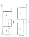
- Fig. 3 shows a pulse width signal of 50% in the upper case and 75% in the lower case.
- Pulse width signal corresponds to the pulse width of half the period. It turns in Dependence of the pulse width on different blower speeds. The relationship between pulse width in% and the fan speed is shown by way of example in FIG. 4. The larger the pulse width signal is, the higher the speed.
- Line a shows the ratio at new condition, line b after a certain wear.
- the actual speed signal is detected by means of the Hall sensor 7 and the control unit. 3 forwarded.
- the slope of the curve is u.a. depending on the total resistance of the Heater as well as the specimen scattering and condition in particular the mechanical Bearing 5 of the fan motor 8.
- a higher pulse width signal is equivalent to a higher electrical power consumption of the fan motor 8. Due to the individual Resistance of the heater including the individual exhaust pipe must be the measurement of the original condition on site in the house and not in the factory at the final inspection happen.
- the mechanical bearings 5 of such a motor 8 are subject to wear. With increasing Operating hours, the bearing friction increases until after years, finally, the friction can be so high that the blower does not start anymore. The heater falls in one such case. However, increased bearing friction also causes the characteristic curve Speed continues to shift across pulse width, i. increases for a given speed the pulse width signal continues to increase. This causes the electrical Power consumption of the fan motor 8 increases. This circumstance makes this one use described method.
- a Maintenance signal is generated, which then e.g. as a text message on the display 6 of the Control unit 3 or even on external display media is displayed.
- the allowed Deviation from the pulse width signal mean is chosen so that the maintenance signal is generated before the blower wear is so high that the fan 2 is no longer starts.
Landscapes
- Engineering & Computer Science (AREA)
- Mechanical Engineering (AREA)
- General Engineering & Computer Science (AREA)
- Control Of Positive-Displacement Air Blowers (AREA)
Abstract
Description
Claims (7)
- Verfahren zum Überwachen eines Gebläses (2) mit Drehzahlerfassung vorzugsweise eines Heizgerätes, dadurch gekennzeichnet, dass bei vorgegebener Drehzahl mindestens einmal ein für die Belastung des Gebläses (2) relevantes Signal erfasst und gespeichert wird, zu einem späteren Zeitpunkt bei identischer Drehzahl wieder das für die Belastung des Gebläses (2) relevante Signal erfasst wird, die Signalwerte verglichen werden ein und bei einer Abweichung der Signalwerte, welche auf einen signifikanten Anstieg der Belastung schließen lassen, ein Signal zur Einleitung einer Wartung ausgegeben wird.
- Verfahren zum Überwachen eines Gebläses (2) mit Drehzahlerfassung vorzugsweise eines Heizgerätes, dadurch gekennzeichnet, dass bei einem vorgegebenen der Belastung des Gebläses (2) relevantes Signal mindestens einmal die Drehzahl des Gebläses (2) erfasst und gespeichert wird, zu einem späteren Zeitpunkt bei identischem der Belastung des Gebläses (2) relevantes Signal wieder die Drehzahl des Gebläses (2) erfasst wird, die Drehzahlen verglichen werden und bei einer signifikanten Reduzierung der Drehzahl ein Signal zur Einleitung einer Wartung ausgegeben wird.
- Verfahren zum Überwachen eines Gebläses (2) mit Drehzahlerfassung gemäß Anspruch 1 oder 2, dadurch gekennzeichnet, dass das für die Belastung des Gebläses (2) relevantes Signal eine Pulsweitenerfassung enthält.
- Verfahren zum Überwachen eines Gebläses (2) mit Drehzahlerfassung gemäß einem der Ansprüche 1 bis 3, dadurch gekennzeichnet, dass das für die Belastung relevantes Signal eine Strom- und / oder Spannungserfassung enthält.
- Verfahren zum Überwachen eines Gebläses (2) mit Drehzahlerfassung gemäß einem der Ansprüche 1 bis 4, dadurch gekennzeichnet, dass zusätzlich die Lufttemperatur erfasst und beim Vergleich berücksichtigt wird.
- Verfahren zum Überwachen eines Gebläses (2) mit Drehzahlerfassung gemäß einem der Ansprüche 1 bis 5, dadurch gekennzeichnet, dass die Drehzahl mittels Hallsensor (7) erfasst wird.
- Verfahren zum Überwachen eines Gebläses (2) mit Drehzahlerfassung gemäß einem der Ansprüche 1 bis 6, dadurch gekennzeichnet, dass das Signal zur Einleitung einer Wartung in Form einer Anzeige am Gerät, eines Warntons und / oder über eine Datenverbindung vorzugsweise zu einem Fachinstallateur ausgegeben wird.
Applications Claiming Priority (4)
| Application Number | Priority Date | Filing Date | Title |
|---|---|---|---|
| DE102004015521 | 2004-03-30 | ||
| DE102004015521 | 2004-03-30 | ||
| AT8562004A AT500890B8 (de) | 2004-05-17 | 2004-05-17 | Verfahren zum überwachen eines gebläses mit drehzahlerfassung |
| AT8562004 | 2004-05-17 |
Publications (2)
| Publication Number | Publication Date |
|---|---|
| EP1582748A2 true EP1582748A2 (de) | 2005-10-05 |
| EP1582748A3 EP1582748A3 (de) | 2012-06-13 |
Family
ID=34887963
Family Applications (1)
| Application Number | Title | Priority Date | Filing Date |
|---|---|---|---|
| EP20050006349 Ceased EP1582748A3 (de) | 2004-03-30 | 2005-03-23 | Verfahren zum Überwachen eines Gebläses |
Country Status (1)
| Country | Link |
|---|---|
| EP (1) | EP1582748A3 (de) |
Cited By (1)
| Publication number | Priority date | Publication date | Assignee | Title |
|---|---|---|---|---|
| CN102536954A (zh) * | 2011-12-24 | 2012-07-04 | 大连交通大学 | 一种活塞式多级液压缸的控制系统 |
Citations (5)
| Publication number | Priority date | Publication date | Assignee | Title |
|---|---|---|---|---|
| JPH08178273A (ja) | 1994-12-28 | 1996-07-12 | Tokyo Gas Co Ltd | 給湯装置 |
| EP0724122A1 (de) * | 1995-01-30 | 1996-07-31 | Gastar Co., Ltd. | Verbrennungsvorrichtung |
| JPH09329331A (ja) * | 1996-06-10 | 1997-12-22 | Noritz Corp | ファンモータ制御装置 |
| JPH1151388A (ja) | 1997-08-01 | 1999-02-26 | Hanshin Electric Co Ltd | 燃焼制御装置 |
| DE10154783A1 (de) * | 2001-11-08 | 2003-05-22 | Buderus Heiztechnik Gmbh | Verfahren zur Überwachung des Luftvolumenstromes bei einem Gebläse |
-
2005
- 2005-03-23 EP EP20050006349 patent/EP1582748A3/de not_active Ceased
Patent Citations (5)
| Publication number | Priority date | Publication date | Assignee | Title |
|---|---|---|---|---|
| JPH08178273A (ja) | 1994-12-28 | 1996-07-12 | Tokyo Gas Co Ltd | 給湯装置 |
| EP0724122A1 (de) * | 1995-01-30 | 1996-07-31 | Gastar Co., Ltd. | Verbrennungsvorrichtung |
| JPH09329331A (ja) * | 1996-06-10 | 1997-12-22 | Noritz Corp | ファンモータ制御装置 |
| JPH1151388A (ja) | 1997-08-01 | 1999-02-26 | Hanshin Electric Co Ltd | 燃焼制御装置 |
| DE10154783A1 (de) * | 2001-11-08 | 2003-05-22 | Buderus Heiztechnik Gmbh | Verfahren zur Überwachung des Luftvolumenstromes bei einem Gebläse |
Cited By (1)
| Publication number | Priority date | Publication date | Assignee | Title |
|---|---|---|---|---|
| CN102536954A (zh) * | 2011-12-24 | 2012-07-04 | 大连交通大学 | 一种活塞式多级液压缸的控制系统 |
Also Published As
| Publication number | Publication date |
|---|---|
| EP1582748A3 (de) | 2012-06-13 |
Similar Documents
| Publication | Publication Date | Title |
|---|---|---|
| EP0030736A2 (de) | Regelvorrichtung für die Verbrennungsluftmenge einer Feuerstätte | |
| EP3825623B1 (de) | Heizgerät mit notbetriebsregelung | |
| EP4060235B1 (de) | Verfahren zum betreiben eines heizgerätes mit elektronischem gas-luftverbund, und heizgerät | |
| DE10109808C2 (de) | Verfahren und Vorrichtung zur Anpassung eines brennerbetriebenen Heizgerätes an ein Luft-Abgas-System | |
| EP2017531A2 (de) | Verfahren zur Überprüfung eines Ionisationselektrodensignals bei Brennern | |
| DE4117611A1 (de) | Einrichtung zur ueberwachung eines variablen luftstromes | |
| AT408033B (de) | Verfahren zur anpassung eines brennerbeheizten heizgerätes | |
| AT500890B1 (de) | Verfahren zum überwachen eines gebläses mit drehzahlerfassung | |
| EP4027058B1 (de) | Verfahren und anordnung zur erkennung von flüssigkeit in einem gebläse eines heizgerätes | |
| DE10140388C2 (de) | Heizgerät für mobile Anwendungen | |
| EP0614051B1 (de) | Feuerungsautomat | |
| EP3896339B1 (de) | Verfahren zur anpassung einer steuerung eines heizgeräts | |
| DE60107782T2 (de) | Verfahren und Vorrichtung zur Überwachung des Füllungszustandes einer Kraftfahrzeugklimaanlage | |
| EP1239220B1 (de) | Verfahren zur Regelung eines Gasverbrennungsgerätes, insbesondere eines Gasheizgerätes | |
| EP1772673A1 (de) | Verfahren und Vorrichtung zur Überwachung sich bildender Ablagerungen von Feststoffteilchen, insbesondere in einer Brennstoffleitung einer Gasturbine | |
| DE3931095C2 (de) | Schaltung zum Bilden eines Abschaltsignals eines gasbeheizten Gerätes | |
| DE102004063992B4 (de) | Verfahren zur Steuerung einer Feuerungseinrichtung und Feuerungseinrichtung | |
| DE102007007414B3 (de) | Zirkulations-Automat | |
| AT413300B (de) | Notlaufprogramm für heizungsgeräte | |
| EP1260766B1 (de) | Verfahren zur Anpassung eines brennerbeheizten Heizgerätes an ein Luft-Abgassystem | |
| EP1616134B1 (de) | Luftheizgerät mit einer vorrichtung zur flammüberwachung | |
| DE102007014032A1 (de) | Vorrichtung zum Verbrennen fossiler Brennstoffe | |
| EP1408314A2 (de) | Vorrichtung und Verfahren zur Massenstrommessung | |
| DE202004014397U1 (de) | Abgasanalysegerät mit Steuerungsfunktion | |
| DE10360256A1 (de) | Anordnung zur Überwachung der Heizwasserqualität |
Legal Events
| Date | Code | Title | Description |
|---|---|---|---|
| PUAI | Public reference made under article 153(3) epc to a published international application that has entered the european phase |
Free format text: ORIGINAL CODE: 0009012 |
|
| AK | Designated contracting states |
Kind code of ref document: A2 Designated state(s): AT BE BG CH CY CZ DE DK EE ES FI FR GB GR HU IE IS IT LI LT LU MC NL PL PT RO SE SI SK TR |
|
| AX | Request for extension of the european patent |
Extension state: AL BA HR LV MK YU |
|
| PUAL | Search report despatched |
Free format text: ORIGINAL CODE: 0009013 |
|
| AK | Designated contracting states |
Kind code of ref document: A3 Designated state(s): AT BE BG CH CY CZ DE DK EE ES FI FR GB GR HU IE IS IT LI LT LU MC NL PL PT RO SE SI SK TR |
|
| AX | Request for extension of the european patent |
Extension state: AL BA HR LV MK YU |
|
| RIC1 | Information provided on ipc code assigned before grant |
Ipc: F04D 27/02 20060101AFI20120508BHEP Ipc: F23N 5/24 20060101ALI20120508BHEP |
|
| 17P | Request for examination filed |
Effective date: 20121210 |
|
| AKX | Designation fees paid |
Designated state(s): AT BE BG CH CY CZ DE DK EE ES FI FR GB GR HU IE IS IT LI LT LU MC NL PL PT RO SE SI SK TR |
|
| 17Q | First examination report despatched |
Effective date: 20130306 |
|
| STAA | Information on the status of an ep patent application or granted ep patent |
Free format text: STATUS: THE APPLICATION HAS BEEN REFUSED |
|
| 18R | Application refused |
Effective date: 20151219 |