EP1582742A2 - Control valve for variable capacity compressors - Google Patents
Control valve for variable capacity compressors Download PDFInfo
- Publication number
- EP1582742A2 EP1582742A2 EP05004982A EP05004982A EP1582742A2 EP 1582742 A2 EP1582742 A2 EP 1582742A2 EP 05004982 A EP05004982 A EP 05004982A EP 05004982 A EP05004982 A EP 05004982A EP 1582742 A2 EP1582742 A2 EP 1582742A2
- Authority
- EP
- European Patent Office
- Prior art keywords
- valve body
- extraction valve
- extraction
- communicating port
- chamber
- Prior art date
- Legal status (The legal status is an assumption and is not a legal conclusion. Google has not performed a legal analysis and makes no representation as to the accuracy of the status listed.)
- Granted
Links
Images


Classifications
-
- F—MECHANICAL ENGINEERING; LIGHTING; HEATING; WEAPONS; BLASTING
- F16—ENGINEERING ELEMENTS AND UNITS; GENERAL MEASURES FOR PRODUCING AND MAINTAINING EFFECTIVE FUNCTIONING OF MACHINES OR INSTALLATIONS; THERMAL INSULATION IN GENERAL
- F16K—VALVES; TAPS; COCKS; ACTUATING-FLOATS; DEVICES FOR VENTING OR AERATING
- F16K31/00—Actuating devices; Operating means; Releasing devices
- F16K31/02—Actuating devices; Operating means; Releasing devices electric; magnetic
- F16K31/06—Actuating devices; Operating means; Releasing devices electric; magnetic using a magnet, e.g. diaphragm valves, cutting off by means of a liquid
- F16K31/0603—Multiple-way valves
- F16K31/0606—Multiple-way valves fluid passing through the solenoid coil
-
- B—PERFORMING OPERATIONS; TRANSPORTING
- B63—SHIPS OR OTHER WATERBORNE VESSELS; RELATED EQUIPMENT
- B63H—MARINE PROPULSION OR STEERING
- B63H20/00—Outboard propulsion units, e.g. outboard motors or Z-drives; Arrangements thereof on vessels
-
- F—MECHANICAL ENGINEERING; LIGHTING; HEATING; WEAPONS; BLASTING
- F04—POSITIVE - DISPLACEMENT MACHINES FOR LIQUIDS; PUMPS FOR LIQUIDS OR ELASTIC FLUIDS
- F04B—POSITIVE-DISPLACEMENT MACHINES FOR LIQUIDS; PUMPS
- F04B27/00—Multi-cylinder pumps specially adapted for elastic fluids and characterised by number or arrangement of cylinders
- F04B27/08—Multi-cylinder pumps specially adapted for elastic fluids and characterised by number or arrangement of cylinders having cylinders coaxial with, or parallel or inclined to, main shaft axis
- F04B27/14—Control
- F04B27/16—Control of pumps with stationary cylinders
- F04B27/18—Control of pumps with stationary cylinders by varying the relative positions of a swash plate and a cylinder block
- F04B27/1804—Controlled by crankcase pressure
-
- F—MECHANICAL ENGINEERING; LIGHTING; HEATING; WEAPONS; BLASTING
- F16—ENGINEERING ELEMENTS AND UNITS; GENERAL MEASURES FOR PRODUCING AND MAINTAINING EFFECTIVE FUNCTIONING OF MACHINES OR INSTALLATIONS; THERMAL INSULATION IN GENERAL
- F16K—VALVES; TAPS; COCKS; ACTUATING-FLOATS; DEVICES FOR VENTING OR AERATING
- F16K31/00—Actuating devices; Operating means; Releasing devices
- F16K31/02—Actuating devices; Operating means; Releasing devices electric; magnetic
- F16K31/06—Actuating devices; Operating means; Releasing devices electric; magnetic using a magnet, e.g. diaphragm valves, cutting off by means of a liquid
- F16K31/0603—Multiple-way valves
- F16K31/0624—Lift valves
- F16K31/0634—Lift valves with fixed seats positioned between movable valve members
-
- F—MECHANICAL ENGINEERING; LIGHTING; HEATING; WEAPONS; BLASTING
- F16—ENGINEERING ELEMENTS AND UNITS; GENERAL MEASURES FOR PRODUCING AND MAINTAINING EFFECTIVE FUNCTIONING OF MACHINES OR INSTALLATIONS; THERMAL INSULATION IN GENERAL
- F16K—VALVES; TAPS; COCKS; ACTUATING-FLOATS; DEVICES FOR VENTING OR AERATING
- F16K31/00—Actuating devices; Operating means; Releasing devices
- F16K31/02—Actuating devices; Operating means; Releasing devices electric; magnetic
- F16K31/06—Actuating devices; Operating means; Releasing devices electric; magnetic using a magnet, e.g. diaphragm valves, cutting off by means of a liquid
- F16K31/0675—Electromagnet aspects, e.g. electric supply therefor
-
- B—PERFORMING OPERATIONS; TRANSPORTING
- B63—SHIPS OR OTHER WATERBORNE VESSELS; RELATED EQUIPMENT
- B63B—SHIPS OR OTHER WATERBORNE VESSELS; EQUIPMENT FOR SHIPPING
- B63B2221/00—Methods and means for joining members or elements
- B63B2221/08—Methods and means for joining members or elements by means of threaded members, e.g. screws, threaded bolts or nuts
-
- F—MECHANICAL ENGINEERING; LIGHTING; HEATING; WEAPONS; BLASTING
- F04—POSITIVE - DISPLACEMENT MACHINES FOR LIQUIDS; PUMPS FOR LIQUIDS OR ELASTIC FLUIDS
- F04B—POSITIVE-DISPLACEMENT MACHINES FOR LIQUIDS; PUMPS
- F04B27/00—Multi-cylinder pumps specially adapted for elastic fluids and characterised by number or arrangement of cylinders
- F04B27/08—Multi-cylinder pumps specially adapted for elastic fluids and characterised by number or arrangement of cylinders having cylinders coaxial with, or parallel or inclined to, main shaft axis
- F04B27/14—Control
- F04B27/16—Control of pumps with stationary cylinders
- F04B27/18—Control of pumps with stationary cylinders by varying the relative positions of a swash plate and a cylinder block
- F04B27/1804—Controlled by crankcase pressure
- F04B2027/1809—Controlled pressure
- F04B2027/1813—Crankcase pressure
-
- F—MECHANICAL ENGINEERING; LIGHTING; HEATING; WEAPONS; BLASTING
- F04—POSITIVE - DISPLACEMENT MACHINES FOR LIQUIDS; PUMPS FOR LIQUIDS OR ELASTIC FLUIDS
- F04B—POSITIVE-DISPLACEMENT MACHINES FOR LIQUIDS; PUMPS
- F04B27/00—Multi-cylinder pumps specially adapted for elastic fluids and characterised by number or arrangement of cylinders
- F04B27/08—Multi-cylinder pumps specially adapted for elastic fluids and characterised by number or arrangement of cylinders having cylinders coaxial with, or parallel or inclined to, main shaft axis
- F04B27/14—Control
- F04B27/16—Control of pumps with stationary cylinders
- F04B27/18—Control of pumps with stationary cylinders by varying the relative positions of a swash plate and a cylinder block
- F04B27/1804—Controlled by crankcase pressure
- F04B2027/1822—Valve-controlled fluid connection
- F04B2027/1827—Valve-controlled fluid connection between crankcase and discharge chamber
-
- F—MECHANICAL ENGINEERING; LIGHTING; HEATING; WEAPONS; BLASTING
- F04—POSITIVE - DISPLACEMENT MACHINES FOR LIQUIDS; PUMPS FOR LIQUIDS OR ELASTIC FLUIDS
- F04B—POSITIVE-DISPLACEMENT MACHINES FOR LIQUIDS; PUMPS
- F04B27/00—Multi-cylinder pumps specially adapted for elastic fluids and characterised by number or arrangement of cylinders
- F04B27/08—Multi-cylinder pumps specially adapted for elastic fluids and characterised by number or arrangement of cylinders having cylinders coaxial with, or parallel or inclined to, main shaft axis
- F04B27/14—Control
- F04B27/16—Control of pumps with stationary cylinders
- F04B27/18—Control of pumps with stationary cylinders by varying the relative positions of a swash plate and a cylinder block
- F04B27/1804—Controlled by crankcase pressure
- F04B2027/1822—Valve-controlled fluid connection
- F04B2027/1831—Valve-controlled fluid connection between crankcase and suction chamber
-
- F—MECHANICAL ENGINEERING; LIGHTING; HEATING; WEAPONS; BLASTING
- F04—POSITIVE - DISPLACEMENT MACHINES FOR LIQUIDS; PUMPS FOR LIQUIDS OR ELASTIC FLUIDS
- F04B—POSITIVE-DISPLACEMENT MACHINES FOR LIQUIDS; PUMPS
- F04B27/00—Multi-cylinder pumps specially adapted for elastic fluids and characterised by number or arrangement of cylinders
- F04B27/08—Multi-cylinder pumps specially adapted for elastic fluids and characterised by number or arrangement of cylinders having cylinders coaxial with, or parallel or inclined to, main shaft axis
- F04B27/14—Control
- F04B27/16—Control of pumps with stationary cylinders
- F04B27/18—Control of pumps with stationary cylinders by varying the relative positions of a swash plate and a cylinder block
- F04B27/1804—Controlled by crankcase pressure
- F04B2027/184—Valve controlling parameter
- F04B2027/1854—External parameters
-
- F—MECHANICAL ENGINEERING; LIGHTING; HEATING; WEAPONS; BLASTING
- F04—POSITIVE - DISPLACEMENT MACHINES FOR LIQUIDS; PUMPS FOR LIQUIDS OR ELASTIC FLUIDS
- F04B—POSITIVE-DISPLACEMENT MACHINES FOR LIQUIDS; PUMPS
- F04B27/00—Multi-cylinder pumps specially adapted for elastic fluids and characterised by number or arrangement of cylinders
- F04B27/08—Multi-cylinder pumps specially adapted for elastic fluids and characterised by number or arrangement of cylinders having cylinders coaxial with, or parallel or inclined to, main shaft axis
- F04B27/14—Control
- F04B27/16—Control of pumps with stationary cylinders
- F04B27/18—Control of pumps with stationary cylinders by varying the relative positions of a swash plate and a cylinder block
- F04B27/1804—Controlled by crankcase pressure
- F04B2027/184—Valve controlling parameter
- F04B2027/1859—Suction pressure
Landscapes
- Engineering & Computer Science (AREA)
- General Engineering & Computer Science (AREA)
- Mechanical Engineering (AREA)
- Physics & Mathematics (AREA)
- Electromagnetism (AREA)
- Chemical & Material Sciences (AREA)
- Combustion & Propulsion (AREA)
- Ocean & Marine Engineering (AREA)
- Compressors, Vaccum Pumps And Other Relevant Systems (AREA)
- Magnetically Actuated Valves (AREA)
- Control Of Positive-Displacement Pumps (AREA)
Abstract
Description
Claims (7)
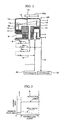
- A control valve for a variable capacity compressor of integrated feed valve/extraction valve type, which comprises:a main valve body provided with a discharge duct-communicating port, with an outflow side crank chamber-communicating port, with an inflow side crank chamber-communicating port, with an intake duct-communicating port, with a feed valve hole interposed between the discharge duct-communicating port and the outflow side crank chamber-communicating port, and with an extraction valve hole interposed between the inflow side crank chamber-communicating port and the intake duct-communicating port;a feed valve body which is capable of opening and closing the feed valve hole to a full or certain extent;an extraction valve body which is capable of opening and closing the extraction valve hole; anda solenoid magnetization portion which is capable of actuating the opening and closing of the feed valve body and of the extraction valve body;which is characterized in that it is enabled, through the actuation of the solenoid magnetization portion, to take a first status wherein the feed valve body is fully opened and the extraction valve body is actuated to secure a minimum flow rate, a second status wherein the feed valve body is fully closed and the extraction valve body is fully opened; and an intermediate status between the first status and the second status wherein the feed valve body is opened to a certain extent depending on the value of control current; and that a predetermined flow rate is secured irrespective of the opening degree of the extraction valve body.
- The control valve according to claim 1, wherein a cross-sectional area of the cooling medium flow at the extraction valve hole is formed smaller than a cross-sectional area of the cooling medium flow at a region of the extraction body when the extraction valve body is fully opened.
- The control valve according to claim 1 or 2, wherein when the length of the extraction valve body is defined as L2 and the depth of an extraction valve chamber where the extraction valve body is disposed is defined as L1, the extraction valve body is configured to form a space between the extraction valve body and an extraction valve seat portion formed in the main valve body, the height of the space corresponding to a width of L1-L2 in the first status, thereby permitting a predetermined quantity of the cooling medium to flow from the inflow side crank chamber-communicating port through the space to the intake duct-communicating port.
- The control valve according to claim 3, wherein the extraction valve body is disposed in the extraction valve chamber formed at an upper portion of a plunger and fixed to an upper portion of a push rod formed integral with the plunger; the extraction valve chamber is communicated with the intake duct-communicating port; and the push rod is enabled, due to the resilient force of a plunger spring, to move upward together with the plunger and to contact with the extraction valve seat portion, thereby permitting an upper surface portion of the extraction valve body not to completely close the extraction valve hole but leaving a predetermined gap unclosed.
- The control valve according to claim 1 or 2, wherein the extraction valve body is disposed in the extraction valve chamber formed at an upper portion of a plunger and fixed to an upper portion of a push rod formed integral with the plunger; the extraction valve chamber is communicated with the intake duct-communicating port; and the push rod is enabled, due to the resilient force of a plunger spring, to move upward together with the plunger and to approach the extraction valve seat portion of the main valve body, enabling an upper surface portion of the extraction valve body to enter into the extraction valve hole.
- The control valve according to claim 3 or 4, wherein the cooling medium inhaled from an intake chamber which is communicated with an inlet duct is compressed and discharged into a discharge chamber which is communicated with a discharge duct; the pressure of the cooling medium is controlled by means of a control valve provided with the solenoid magnetization portion comprising the plunger; the solenoid magnetization portion is provided therein with a pressure sensitive portion; the feed valve body interposed between the discharge duct and the crank chamber, and the extraction valve body interposed between the crank chamber and the inlet duct are adapted to be opened and closed by the actuation of the solenoid magnetization portion and by the balance between the reaction of a bellows and the cooling medium sucking pressure Ps;
the housing of the control valve is configured to have a vertically elongated hollow cylindrical body, the hollow portion of which being constituted by, mentioned from top to bottom, a feed valve chamber communicated with the outflow side crank chamber-communicating port, a feed valve hole, a discharge duct-communicating port, a valve rod supporting portion, an extraction valve hole communicated with the inflow side crank chamber communicating port, and a plunger chamber communicated with the inlet duct-communicating port; and
the hollow portion of the cylindrical body is provided therein with a valve rod formed integral with the feed valve body which is positioned in the feed valve chamber, and with the push rod formed integral with the plunger which is positioned in the plunger chamber, the push rod being provided with the extraction valve body. - The control valve according to claim 5, wherein the coolingmedium inhaled from an intake chamber which is communicated with an inlet duct is compressed and discharged into a discharge chamber which is communicated with a discharge duct; the pressure of the cooling medium is controlled by means of a control valve provided with the solenoid magnetization portion comprising the plunger; the solenoid magnetization portion is provided therein with the pressure sensitive portion; the feed valve body interposed between the discharge duct and the crank chamber, and the extraction valve body interposed between the crank chamber and the inlet duct are adapted to be opened and closed by the actuation of the solenoidmagnetization portion and by the balance between the reaction of a bellows and the cooling medium sucking pressure Ps;
the housing of the control valve is configured to have a vertically elongated hollow cylindrical body, the hollow portion of which being constituted by, mentioned from top to bottom, a feed valve chamber communicated with the outflow side crank chamber-communicating port, a feed valve hole, a discharge duct-communicating port, a valve rod supporting portion, an extraction valve hole communicated with the inflow side crank chamber communicating port, and a plunger chamber communicated with the inlet duct-communicating port; and
the hollow portion of the cylindrical body is provided therein with a valve rod formed integral with the feed valve body which is positioned in the feed valve chamber, the valve rod being provided integrally with the plunger disposed in the plunger chamber and with an extraction valve body, the extraction valve body having an outer diameter which is smaller than an inner diameter of the extraction valve hole, thereby permitting the cooling medium to continue to flow at a very small flow rate even if the extraction valve body is moved into a closed state.
Applications Claiming Priority (2)
| Application Number | Priority Date | Filing Date | Title |
|---|---|---|---|
| JP2004088471A JP4456906B2 (en) | 2004-03-25 | 2004-03-25 | Control valve for variable capacity compressor |
| JP2004088471 | 2004-03-25 |
Publications (3)
| Publication Number | Publication Date |
|---|---|
| EP1582742A2 true EP1582742A2 (en) | 2005-10-05 |
| EP1582742A3 EP1582742A3 (en) | 2005-12-28 |
| EP1582742B1 EP1582742B1 (en) | 2007-06-13 |
Family
ID=34879882
Family Applications (1)
| Application Number | Title | Priority Date | Filing Date |
|---|---|---|---|
| EP05004982A Active EP1582742B1 (en) | 2004-03-25 | 2005-03-08 | Control valve for variable capacity compressors |
Country Status (6)
| Country | Link |
|---|---|
| US (1) | US7128304B2 (en) |
| EP (1) | EP1582742B1 (en) |
| JP (1) | JP4456906B2 (en) |
| KR (1) | KR100709287B1 (en) |
| CN (1) | CN100356059C (en) |
| DE (1) | DE602005001338T2 (en) |
Cited By (3)
| Publication number | Priority date | Publication date | Assignee | Title |
|---|---|---|---|---|
| EP2733351A1 (en) * | 2012-11-15 | 2014-05-21 | TGK CO., Ltd. | Composite valve |
| EP3604806A4 (en) * | 2017-03-28 | 2020-09-02 | Eagle Industry Co., Ltd. | Capacity control valve |
| US11536389B2 (en) | 2017-08-28 | 2022-12-27 | Eagle Industry Co., Ltd. | Electromagnetic valve |
Families Citing this family (23)
| Publication number | Priority date | Publication date | Assignee | Title |
|---|---|---|---|---|
| JP2006194114A (en) * | 2005-01-12 | 2006-07-27 | Tgk Co Ltd | Control valve for variable displacement compressor |
| JP4714626B2 (en) * | 2006-04-13 | 2011-06-29 | 株式会社不二工機 | Control valve for variable displacement compressor |
| JP4695032B2 (en) * | 2006-07-19 | 2011-06-08 | サンデン株式会社 | Volume control valve for variable capacity compressor |
| JP4925800B2 (en) * | 2006-11-30 | 2012-05-09 | カルソニックカンセイ株式会社 | Control valve for variable displacement compressor |
| EP1929905B1 (en) * | 2006-12-06 | 2012-02-08 | RHEAVENDORS SERVICES S.p.A. | Beverage dispensing machine and operating method |
| JP5424397B2 (en) * | 2009-12-04 | 2014-02-26 | サンデン株式会社 | Control valve and swash plate type variable capacity compressor with control valve |
| JP5699259B2 (en) * | 2011-01-07 | 2015-04-08 | 株式会社テージーケー | Control valve for variable capacity compressor |
| CN103547804B (en) * | 2011-05-23 | 2016-03-09 | 学校法人斗源学院 | Control valve for variable displacement compressor and the method for the manufacture of this control valve |
| KR101258342B1 (en) * | 2011-05-23 | 2013-04-25 | 주식회사 두원전자 | Control valve for a variable displacement compressor |
| CN103890391B (en) * | 2011-10-20 | 2016-05-04 | 学校法人斗源学院 | For the control valve of compressor |
| JP5641031B2 (en) * | 2012-01-16 | 2014-12-17 | 株式会社デンソー | Electromagnetic actuator |
| EP2857681B1 (en) | 2012-05-24 | 2019-08-28 | Eagle Industry Co., Ltd. | Volume control valve |
| KR101336160B1 (en) * | 2012-08-13 | 2013-12-03 | (주)신한전기 | Capacity control valve for variable displacement compressor |
| JP6355617B2 (en) * | 2015-12-16 | 2018-07-11 | 株式会社不二工機 | Control valve for variable displacement compressor |
| JP6500186B2 (en) * | 2016-02-25 | 2019-04-17 | 株式会社テージーケー | Control valve for variable displacement compressor |
| JP6500185B2 (en) * | 2016-02-25 | 2019-04-17 | 株式会社テージーケー | Control valve for variable displacement compressor |
| CN108071824B (en) | 2016-06-13 | 2021-08-10 | 株式会社Tgk | Control valve for variable displacement compressor |
| JP6714274B2 (en) * | 2016-06-13 | 2020-06-24 | 株式会社テージーケー | Control valve for variable capacity compressor |
| KR101892186B1 (en) * | 2016-07-01 | 2018-08-28 | 동일기계공업 주식회사 | Control valve of variable displacement compressor |
| JP6632503B2 (en) * | 2016-09-30 | 2020-01-22 | 株式会社不二工機 | Control valve for variable displacement compressor |
| JP6924476B2 (en) * | 2017-04-07 | 2021-08-25 | 株式会社テージーケー | Control valve for variable displacement compressor |
| DE102017117280B4 (en) * | 2017-05-17 | 2018-12-06 | Schaeffler Technologies AG & Co. KG | Hydraulic clutch actuation system with dust protection |
| KR102100294B1 (en) * | 2018-11-19 | 2020-04-13 | 동일기계공업 주식회사 | Exhaust control valve for variable displacement compressor to prevent foreign substance |
Citations (2)
| Publication number | Priority date | Publication date | Assignee | Title |
|---|---|---|---|---|
| US4894999A (en) * | 1988-03-31 | 1990-01-23 | Nissan Motor Company, Limited | Automatic air conditioning system with variable displacement compressor, for automotive vehicles |
| EP1247981A2 (en) * | 2001-04-06 | 2002-10-09 | Fujikoki Corporation | Control valve for variable capacity compressors |
Family Cites Families (18)
| Publication number | Priority date | Publication date | Assignee | Title |
|---|---|---|---|---|
| US5051631A (en) * | 1990-07-16 | 1991-09-24 | Spx Corporation | Electromagnetic solenoid valve with variable force motor |
| JP3490557B2 (en) * | 1995-10-31 | 2004-01-26 | 株式会社テージーケー | Capacity control device for variable capacity compressor |
| JP3432994B2 (en) * | 1996-04-01 | 2003-08-04 | 株式会社豊田自動織機 | Control valve for variable displacement compressor |
| JP3585148B2 (en) * | 1996-12-16 | 2004-11-04 | 株式会社豊田自動織機 | Control valve for variable displacement compressor |
| JP3585150B2 (en) * | 1997-01-21 | 2004-11-04 | 株式会社豊田自動織機 | Control valve for variable displacement compressor |
| JP4160669B2 (en) * | 1997-11-28 | 2008-10-01 | 株式会社不二工機 | Control valve for variable displacement compressor |
| JP3728387B2 (en) * | 1998-04-27 | 2005-12-21 | 株式会社豊田自動織機 | Control valve |
| JP2000161234A (en) * | 1998-11-27 | 2000-06-13 | Toyota Autom Loom Works Ltd | Variable displacement type compressor, and its displacement control valve |
| JP3583951B2 (en) * | 1999-06-07 | 2004-11-04 | 株式会社豊田自動織機 | Capacity control valve |
| JP2001073939A (en) * | 1999-08-31 | 2001-03-21 | Toyota Autom Loom Works Ltd | Control valve for variable displacement compressor and variable displacement compressor |
| JP2001099060A (en) * | 1999-10-04 | 2001-04-10 | Fuji Koki Corp | Control valve for variable displacement compressor |
| JP4205826B2 (en) * | 1999-11-30 | 2009-01-07 | 株式会社不二工機 | Control valve for variable displacement compressor |
| JP2002221153A (en) * | 2001-01-23 | 2002-08-09 | Toyota Industries Corp | Control valve for variable displacement type compressor |
| JP3925091B2 (en) * | 2001-02-28 | 2007-06-06 | 株式会社豊田自動織機 | Control valve for variable capacity compressor and method for adjusting the control valve |
| KR100858604B1 (en) * | 2001-11-30 | 2008-09-17 | 가부시기가이샤 후지고오키 | Control Valve for Variable Capacity Compressors |
| JP4195633B2 (en) * | 2002-04-25 | 2008-12-10 | サンデン株式会社 | Variable displacement compressor with displacement control valve |
| US6848475B2 (en) * | 2002-11-20 | 2005-02-01 | Caterpillar Inc. | Electro-hydraulic valve and system |
| KR100984214B1 (en) * | 2003-01-22 | 2010-09-28 | 가부시키가이샤 발레오 서멀 시스템즈 | Control valve of variable displacement compressor |
-
2004
- 2004-03-25 JP JP2004088471A patent/JP4456906B2/en not_active Expired - Fee Related
-
2005
- 2005-03-08 EP EP05004982A patent/EP1582742B1/en active Active
- 2005-03-08 DE DE602005001338T patent/DE602005001338T2/en not_active Expired - Fee Related
- 2005-03-18 KR KR1020050022653A patent/KR100709287B1/en not_active IP Right Cessation
- 2005-03-21 CN CNB2005100557976A patent/CN100356059C/en not_active Expired - Fee Related
- 2005-03-22 US US11/086,883 patent/US7128304B2/en not_active Expired - Fee Related
Patent Citations (2)
| Publication number | Priority date | Publication date | Assignee | Title |
|---|---|---|---|---|
| US4894999A (en) * | 1988-03-31 | 1990-01-23 | Nissan Motor Company, Limited | Automatic air conditioning system with variable displacement compressor, for automotive vehicles |
| EP1247981A2 (en) * | 2001-04-06 | 2002-10-09 | Fujikoki Corporation | Control valve for variable capacity compressors |
Cited By (5)
| Publication number | Priority date | Publication date | Assignee | Title |
|---|---|---|---|---|
| EP2733351A1 (en) * | 2012-11-15 | 2014-05-21 | TGK CO., Ltd. | Composite valve |
| US9732874B2 (en) | 2012-11-15 | 2017-08-15 | Tgk Co., Ltd. | Composite valve with main valve element and sub-valve element |
| EP3604806A4 (en) * | 2017-03-28 | 2020-09-02 | Eagle Industry Co., Ltd. | Capacity control valve |
| US11401922B2 (en) | 2017-03-28 | 2022-08-02 | Eagle Industry Co., Ltd. | Displacement control valve |
| US11536389B2 (en) | 2017-08-28 | 2022-12-27 | Eagle Industry Co., Ltd. | Electromagnetic valve |
Also Published As
| Publication number | Publication date |
|---|---|
| JP4456906B2 (en) | 2010-04-28 |
| EP1582742B1 (en) | 2007-06-13 |
| EP1582742A3 (en) | 2005-12-28 |
| CN100356059C (en) | 2007-12-19 |
| KR100709287B1 (en) | 2007-04-19 |
| KR20060044399A (en) | 2006-05-16 |
| US20050211939A1 (en) | 2005-09-29 |
| US7128304B2 (en) | 2006-10-31 |
| DE602005001338T2 (en) | 2008-02-14 |
| CN1673531A (en) | 2005-09-28 |
| JP2005273548A (en) | 2005-10-06 |
| DE602005001338D1 (en) | 2007-07-26 |
Similar Documents
| Publication | Publication Date | Title |
|---|---|---|
| EP1582742B1 (en) | Control valve for variable capacity compressors | |
| CN100378329C (en) | Control valve for variable displacement compressor | |
| KR101139062B1 (en) | Control valve for variable displacement compressor | |
| EP1602828A2 (en) | Control valve for variable displacement compressor | |
| JP4422512B2 (en) | Control valve for variable capacity compressor | |
| EP1162370A2 (en) | A capacity control device for a compressor in a refrigerating system | |
| EP1628017A2 (en) | Control valve for variable displacement compressor | |
| EP1179679B1 (en) | Control valve of variable displacement compressor | |
| EP1717444B1 (en) | Displacement control valve for clutchless type variable displacement compressor | |
| EP1225333A2 (en) | Control valve for variable displacement type compressor | |
| EP1155888A2 (en) | Air conditioner | |
| US20060083625A1 (en) | Control valve for variable displacement compressor | |
| EP1155887A2 (en) | Air conditioner | |
| JP4333047B2 (en) | Control valve for variable capacity compressor | |
| JP2005291142A (en) | Control device and pressure control valve for variable displacement compressor | |
| JP4418309B2 (en) | Control valve for variable capacity compressor | |
| JP2004316429A (en) | Control valve for variable capacitance type compressor | |
| JP2006125292A (en) | Control valve for variable displacement compressor | |
| JP2009133237A (en) | Control valve for variable displacement compressor | |
| JP2001193640A (en) | Control valve for variable displacement type compressor | |
| JP2007218168A (en) | Control valve for variable capacity compressor | |
| JP4173073B2 (en) | Control valve for variable capacity compressor | |
| JP2004137922A (en) | Capacity control valve of variable displacement compressor | |
| JP2007303291A (en) | Control valve for variable displacement compressor | |
| JP2007278138A (en) | Control valve for variable displacement compressor and method for adjusting characteristics thereof |
Legal Events
| Date | Code | Title | Description |
|---|---|---|---|
| PUAI | Public reference made under article 153(3) epc to a published international application that has entered the european phase |
Free format text: ORIGINAL CODE: 0009012 |
|
| AK | Designated contracting states |
Kind code of ref document: A2 Designated state(s): AT BE BG CH CY CZ DE DK EE ES FI FR GB GR HU IE IS IT LI LT LU MC NL PL PT RO SE SI SK TR |
|
| AX | Request for extension of the european patent |
Extension state: AL BA HR LV MK YU |
|
| PUAL | Search report despatched |
Free format text: ORIGINAL CODE: 0009013 |
|
| AK | Designated contracting states |
Kind code of ref document: A3 Designated state(s): AT BE BG CH CY CZ DE DK EE ES FI FR GB GR HU IE IS IT LI LT LU MC NL PL PT RO SE SI SK TR |
|
| AX | Request for extension of the european patent |
Extension state: AL BA HR LV MK YU |
|
| 17P | Request for examination filed |
Effective date: 20060628 |
|
| AKX | Designation fees paid |
Designated state(s): DE FR GB IT |
|
| GRAP | Despatch of communication of intention to grant a patent |
Free format text: ORIGINAL CODE: EPIDOSNIGR1 |
|
| GRAS | Grant fee paid |
Free format text: ORIGINAL CODE: EPIDOSNIGR3 |
|
| GRAA | (expected) grant |
Free format text: ORIGINAL CODE: 0009210 |
|
| AK | Designated contracting states |
Kind code of ref document: B1 Designated state(s): DE FR GB IT |
|
| REG | Reference to a national code |
Ref country code: GB Ref legal event code: FG4D |
|
| REF | Corresponds to: |
Ref document number: 602005001338 Country of ref document: DE Date of ref document: 20070726 Kind code of ref document: P |
|
| ET | Fr: translation filed | ||
| PLBE | No opposition filed within time limit |
Free format text: ORIGINAL CODE: 0009261 |
|
| STAA | Information on the status of an ep patent application or granted ep patent |
Free format text: STATUS: NO OPPOSITION FILED WITHIN TIME LIMIT |
|
| 26N | No opposition filed |
Effective date: 20080314 |
|
| PGFP | Annual fee paid to national office [announced via postgrant information from national office to epo] |
Ref country code: DE Payment date: 20080306 Year of fee payment: 4 |
|
| GBPC | Gb: european patent ceased through non-payment of renewal fee |
Effective date: 20090308 |
|
| PG25 | Lapsed in a contracting state [announced via postgrant information from national office to epo] |
Ref country code: DE Free format text: LAPSE BECAUSE OF NON-PAYMENT OF DUE FEES Effective date: 20091001 |
|
| PG25 | Lapsed in a contracting state [announced via postgrant information from national office to epo] |
Ref country code: GB Free format text: LAPSE BECAUSE OF NON-PAYMENT OF DUE FEES Effective date: 20090308 |
|
| PGFP | Annual fee paid to national office [announced via postgrant information from national office to epo] |
Ref country code: FR Payment date: 20110317 Year of fee payment: 7 |
|
| PGFP | Annual fee paid to national office [announced via postgrant information from national office to epo] |
Ref country code: IT Payment date: 20080331 Year of fee payment: 4 |
|
| REG | Reference to a national code |
Ref country code: FR Ref legal event code: ST Effective date: 20121130 |
|
| PG25 | Lapsed in a contracting state [announced via postgrant information from national office to epo] |
Ref country code: FR Free format text: LAPSE BECAUSE OF NON-PAYMENT OF DUE FEES Effective date: 20120402 |