EP1582714A1 - Regeneration system and method for regenerating particulate filter - Google Patents
Regeneration system and method for regenerating particulate filter Download PDFInfo
- Publication number
- EP1582714A1 EP1582714A1 EP05007108A EP05007108A EP1582714A1 EP 1582714 A1 EP1582714 A1 EP 1582714A1 EP 05007108 A EP05007108 A EP 05007108A EP 05007108 A EP05007108 A EP 05007108A EP 1582714 A1 EP1582714 A1 EP 1582714A1
- Authority
- EP
- European Patent Office
- Prior art keywords
- particulate filter
- amount
- regeneration
- particulate matter
- diesel engine
- Prior art date
- Legal status (The legal status is an assumption and is not a legal conclusion. Google has not performed a legal analysis and makes no representation as to the accuracy of the status listed.)
- Granted
Links
Images


Classifications
-
- F—MECHANICAL ENGINEERING; LIGHTING; HEATING; WEAPONS; BLASTING
- F02—COMBUSTION ENGINES; HOT-GAS OR COMBUSTION-PRODUCT ENGINE PLANTS
- F02D—CONTROLLING COMBUSTION ENGINES
- F02D41/00—Electrical control of supply of combustible mixture or its constituents
- F02D41/02—Circuit arrangements for generating control signals
- F02D41/14—Introducing closed-loop corrections
- F02D41/1438—Introducing closed-loop corrections using means for determining characteristics of the combustion gases; Sensors therefor
- F02D41/1444—Introducing closed-loop corrections using means for determining characteristics of the combustion gases; Sensors therefor characterised by the characteristics of the combustion gases
- F02D41/1448—Introducing closed-loop corrections using means for determining characteristics of the combustion gases; Sensors therefor characterised by the characteristics of the combustion gases the characteristics being an exhaust gas pressure
-
- F—MECHANICAL ENGINEERING; LIGHTING; HEATING; WEAPONS; BLASTING
- F01—MACHINES OR ENGINES IN GENERAL; ENGINE PLANTS IN GENERAL; STEAM ENGINES
- F01N—GAS-FLOW SILENCERS OR EXHAUST APPARATUS FOR MACHINES OR ENGINES IN GENERAL; GAS-FLOW SILENCERS OR EXHAUST APPARATUS FOR INTERNAL-COMBUSTION ENGINES
- F01N13/00—Exhaust or silencing apparatus characterised by constructional features
- F01N13/009—Exhaust or silencing apparatus characterised by constructional features having two or more separate purifying devices arranged in series
-
- F—MECHANICAL ENGINEERING; LIGHTING; HEATING; WEAPONS; BLASTING
- F01—MACHINES OR ENGINES IN GENERAL; ENGINE PLANTS IN GENERAL; STEAM ENGINES
- F01N—GAS-FLOW SILENCERS OR EXHAUST APPARATUS FOR MACHINES OR ENGINES IN GENERAL; GAS-FLOW SILENCERS OR EXHAUST APPARATUS FOR INTERNAL-COMBUSTION ENGINES
- F01N9/00—Electrical control of exhaust gas treating apparatus
- F01N9/007—Storing data relevant to operation of exhaust systems for later retrieval and analysis, e.g. to research exhaust system malfunctions
-
- F—MECHANICAL ENGINEERING; LIGHTING; HEATING; WEAPONS; BLASTING
- F02—COMBUSTION ENGINES; HOT-GAS OR COMBUSTION-PRODUCT ENGINE PLANTS
- F02D—CONTROLLING COMBUSTION ENGINES
- F02D41/00—Electrical control of supply of combustible mixture or its constituents
- F02D41/02—Circuit arrangements for generating control signals
- F02D41/021—Introducing corrections for particular conditions exterior to the engine
- F02D41/0235—Introducing corrections for particular conditions exterior to the engine in relation with the state of the exhaust gas treating apparatus
- F02D41/027—Introducing corrections for particular conditions exterior to the engine in relation with the state of the exhaust gas treating apparatus to purge or regenerate the exhaust gas treating apparatus
- F02D41/029—Introducing corrections for particular conditions exterior to the engine in relation with the state of the exhaust gas treating apparatus to purge or regenerate the exhaust gas treating apparatus the exhaust gas treating apparatus being a particulate filter
-
- F—MECHANICAL ENGINEERING; LIGHTING; HEATING; WEAPONS; BLASTING
- F02—COMBUSTION ENGINES; HOT-GAS OR COMBUSTION-PRODUCT ENGINE PLANTS
- F02D—CONTROLLING COMBUSTION ENGINES
- F02D41/00—Electrical control of supply of combustible mixture or its constituents
- F02D41/02—Circuit arrangements for generating control signals
- F02D41/04—Introducing corrections for particular operating conditions
- F02D41/08—Introducing corrections for particular operating conditions for idling
-
- F—MECHANICAL ENGINEERING; LIGHTING; HEATING; WEAPONS; BLASTING
- F02—COMBUSTION ENGINES; HOT-GAS OR COMBUSTION-PRODUCT ENGINE PLANTS
- F02D—CONTROLLING COMBUSTION ENGINES
- F02D41/00—Electrical control of supply of combustible mixture or its constituents
- F02D41/30—Controlling fuel injection
- F02D41/38—Controlling fuel injection of the high pressure type
- F02D41/40—Controlling fuel injection of the high pressure type with means for controlling injection timing or duration
- F02D41/402—Multiple injections
- F02D41/405—Multiple injections with post injections
-
- F—MECHANICAL ENGINEERING; LIGHTING; HEATING; WEAPONS; BLASTING
- F01—MACHINES OR ENGINES IN GENERAL; ENGINE PLANTS IN GENERAL; STEAM ENGINES
- F01N—GAS-FLOW SILENCERS OR EXHAUST APPARATUS FOR MACHINES OR ENGINES IN GENERAL; GAS-FLOW SILENCERS OR EXHAUST APPARATUS FOR INTERNAL-COMBUSTION ENGINES
- F01N2430/00—Influencing exhaust purification, e.g. starting of catalytic reaction, filter regeneration, or the like, by controlling engine operating characteristics
- F01N2430/08—Influencing exhaust purification, e.g. starting of catalytic reaction, filter regeneration, or the like, by controlling engine operating characteristics by modifying ignition or injection timing
- F01N2430/085—Influencing exhaust purification, e.g. starting of catalytic reaction, filter regeneration, or the like, by controlling engine operating characteristics by modifying ignition or injection timing at least a part of the injection taking place during expansion or exhaust stroke
-
- F—MECHANICAL ENGINEERING; LIGHTING; HEATING; WEAPONS; BLASTING
- F01—MACHINES OR ENGINES IN GENERAL; ENGINE PLANTS IN GENERAL; STEAM ENGINES
- F01N—GAS-FLOW SILENCERS OR EXHAUST APPARATUS FOR MACHINES OR ENGINES IN GENERAL; GAS-FLOW SILENCERS OR EXHAUST APPARATUS FOR INTERNAL-COMBUSTION ENGINES
- F01N2560/00—Exhaust systems with means for detecting or measuring exhaust gas components or characteristics
- F01N2560/08—Exhaust systems with means for detecting or measuring exhaust gas components or characteristics the means being a pressure sensor
-
- F—MECHANICAL ENGINEERING; LIGHTING; HEATING; WEAPONS; BLASTING
- F01—MACHINES OR ENGINES IN GENERAL; ENGINE PLANTS IN GENERAL; STEAM ENGINES
- F01N—GAS-FLOW SILENCERS OR EXHAUST APPARATUS FOR MACHINES OR ENGINES IN GENERAL; GAS-FLOW SILENCERS OR EXHAUST APPARATUS FOR INTERNAL-COMBUSTION ENGINES
- F01N3/00—Exhaust or silencing apparatus having means for purifying, rendering innocuous, or otherwise treating exhaust
- F01N3/02—Exhaust or silencing apparatus having means for purifying, rendering innocuous, or otherwise treating exhaust for cooling, or for removing solid constituents of, exhaust
- F01N3/021—Exhaust or silencing apparatus having means for purifying, rendering innocuous, or otherwise treating exhaust for cooling, or for removing solid constituents of, exhaust by means of filters
- F01N3/033—Exhaust or silencing apparatus having means for purifying, rendering innocuous, or otherwise treating exhaust for cooling, or for removing solid constituents of, exhaust by means of filters in combination with other devices
- F01N3/035—Exhaust or silencing apparatus having means for purifying, rendering innocuous, or otherwise treating exhaust for cooling, or for removing solid constituents of, exhaust by means of filters in combination with other devices with catalytic reactors
-
- F—MECHANICAL ENGINEERING; LIGHTING; HEATING; WEAPONS; BLASTING
- F02—COMBUSTION ENGINES; HOT-GAS OR COMBUSTION-PRODUCT ENGINE PLANTS
- F02D—CONTROLLING COMBUSTION ENGINES
- F02D2200/00—Input parameters for engine control
- F02D2200/02—Input parameters for engine control the parameters being related to the engine
- F02D2200/08—Exhaust gas treatment apparatus parameters
- F02D2200/0812—Particle filter loading
-
- F—MECHANICAL ENGINEERING; LIGHTING; HEATING; WEAPONS; BLASTING
- F02—COMBUSTION ENGINES; HOT-GAS OR COMBUSTION-PRODUCT ENGINE PLANTS
- F02D—CONTROLLING COMBUSTION ENGINES
- F02D41/00—Electrical control of supply of combustible mixture or its constituents
- F02D41/02—Circuit arrangements for generating control signals
- F02D41/18—Circuit arrangements for generating control signals by measuring intake air flow
- F02D41/187—Circuit arrangements for generating control signals by measuring intake air flow using a hot wire flow sensor
-
- Y—GENERAL TAGGING OF NEW TECHNOLOGICAL DEVELOPMENTS; GENERAL TAGGING OF CROSS-SECTIONAL TECHNOLOGIES SPANNING OVER SEVERAL SECTIONS OF THE IPC; TECHNICAL SUBJECTS COVERED BY FORMER USPC CROSS-REFERENCE ART COLLECTIONS [XRACs] AND DIGESTS
- Y02—TECHNOLOGIES OR APPLICATIONS FOR MITIGATION OR ADAPTATION AGAINST CLIMATE CHANGE
- Y02T—CLIMATE CHANGE MITIGATION TECHNOLOGIES RELATED TO TRANSPORTATION
- Y02T10/00—Road transport of goods or passengers
- Y02T10/10—Internal combustion engine [ICE] based vehicles
- Y02T10/40—Engine management systems
Definitions
- the present invention relates to regeneration system and method for regenerating a particulate filter, which collects fine exhaust particles (generally referred to as particulate matter) from an exhaust stream of a diesel engine.
- the particulate filter has, for example, a porous ceramic body.
- the particulate filter when the exhaust gas passes through partition walls of the porous ceramic body, the particulate matter is captured by the partition walls and the pores of the porous ceramic body.
- the performance of the particulate filter for capturing the particulate matter is disadvantageously lowered, or a flow resistance of the exhaust gas in the particulate filter is disadvantageously increased.
- the flow resistance of the exhaust gas is increased, a back pressure of the internal combustion engine is increased to cause a decrease in an output power of the engine.
- a regenerating system for regenerating the particulate filter by appropriately removing the particulate matter, which is accumulated in the particulate filter.
- post fuel injection is performed to inject fuel during each expansion stroke (or each exhaust stroke) of the diesel engine and thereby to supply the fuel to the particulate filter.
- the temperature of the particulate filter is increased, so that the accumulated particulate matter is combusted and is removed.
- the regeneration operation of the regeneration system is performed in a running state of the diesel engine. More specifically, the regeneration system is operated when the vehicle is driven to travel by the diesel engine. This is true in the regeneration system recited in Japanese Unexamined Patent Publication No. 2004-1146. However, in some cases, a forceful regeneration operation for forcefully regenerating the particulate filter is performed at the time of maintenance service at an automobile dealer without requiring the traveling of the vehicle.
- the diesel engine In the case of the forceful regeneration operation at the automobile dealer, the diesel engine is placed in the running state, and the post fuel injection is performed during each exhaust stroke.
- the forceful regeneration operation is performed in a manner similar to that of the regeneration operation, which is performed during the traveling of the vehicle.
- the running state of the diesel engine is not suitable for regenerating the particulate filter, resulting in unnecessary waste of the fuel.
- the present invention addresses the above disadvantage.
- a regeneration system for performing a forceful regeneration operation of a particulate filter of a diesel engine installed in a vehicle.
- the regeneration system includes an estimating means, a setting means, a sensing means, a regenerating means and a stop means.
- the estimating means is for estimating an amount of accumulated particulate matter on the particulate filter before initiation of the regeneration operation.
- the estimating means provides at least one estimated value of the amount of accumulated particulate matter.
- the setting means is for setting a maximum operating time period of the regeneration operation based on the at least one estimated value of the amount of accumulated particulate matter.
- the sensing means is for sensing at least one physical quantity, which relates to the amount of accumulated particulate matter.
- the regenerating means is for regenerating the particulate filter in the regeneration operation by performing post fuel injection in the diesel engine during each exhaust stroke of the diesel engine to supply fuel to the particulate filter and thereby to remove the particulate matter from the particulate filter through use of combustion heat of the supplied fuel upon combustion of the supplied fuel.
- the stop means is for stopping the regeneration operation of the regenerating means when one of the following conditions is satisfied: a remaining amount of accumulated particulate matter of the particulate filter, which is determined based on the at least one physical quantity sensed by the sensing means, is equal to or less than a reference value used to determine completion of regeneration of the particulate filter; and elapsed time, which has been measured since the initiation of the current regeneration operation of the regenerating means, reaches an end of the maximum operating time period.
- the amount of particulate matter is estimated before the initiation of the regeneration operation. Then, the maximum operating time period is set based on at least one estimated value of the amount of accumulated particulate matter.
- the elapsed time which has been measured since the initiation of the current regeneration operation of the regenerating means, reaches the end of the maximum operating time period, the regeneration operation is forcefully stopped.
- the regeneration system of the present invention may further include a failure diagnosing means and a storage means.
- the failure diagnosing means is for diagnosing a failure of at least one of the estimating means, the setting means, the sensing means, the regenerating means and the stop means.
- the storage means is for storing failure information when the failure of any one of the at least one of the estimating means, the setting means, the sensing means, the regenerating means and the stop means is sensed by the failure diagnosing means.
- the failure information is indicative of the sensed failure.
- the stop means may stop the regeneration operation of the regenerating means when the failure information is present in the storage means. When one component of the regeneration system fails, the regeneration operation may not be properly performed. Thus, in such a situation, the regeneration operation is stopped to limit waste of the fuel.
- the at least one estimated value of the amount of accumulated particulate matter may include a plurality of estimated values of the amount of accumulated particulate matter.
- the estimating means may estimate the plurality of estimated values of the amount of accumulated particulate matter through a plurality of methods, respectively.
- the setting means may set the maximum operating time period of the regeneration operation based on the plurality of estimated values of the amount of accumulated particulate matter. In this way, the maximum operating time period can be set to correspond with the more accurate amount of accumulated particulate matter.
- the maximum operating time period may be determined based on an average (weighted average) of the estimated values of the amount of accumulated particulate matter.
- the maximum operating time period may be determined based on a sum of a preset value and the average (weighted average) of the estimated values.
- the maximum operating time period may be determined based on a maximum value of a group of the estimated values, which fall within a predetermined range.
- the setting means may set the maximum operating time period of the regeneration operation based on a maximum one of the plurality of estimated values of the amount of accumulated particulate matter.
- the plurality of estimated values of the amount of accumulated particulate matter, which are estimated by the estimating means may include at least two of: an estimated value of the amount of accumulated particulate matter that is estimated by the estimating means based on a pressure difference between an inlet of the particulate filter and an outlet of the particulate filter; an estimated value of the amount of accumulated particulate matter that is estimated by the estimating means based on a weight of the particulate filter; an estimated value of the amount of accumulated particulate matter that is estimated by the estimating means based on elapsed operating time of the diesel engine, which has been measured since an end of a previous forceful regeneration operation of the particulate filter; an estimated value of the amount of accumulated particulate matter that is estimated by the estimating means based on a travel distance of the vehicle, which has been measured since the end of the previous regeneration operation of the particulate filter; and an estimated value of the amount of accumulated particulate matter that is estimated by the estimating means based on a total amount of injected
- the regeneration system may include a rotational speed control means for controlling a rotational speed of the diesel engine.
- the rotational speed control means keeps the rotational speed of the diesel engine higher than a normal idling speed of the diesel engine throughout a predetermined time period, which starts at time of the initiation of the current regeneration operation. In this way, an increase rate of the temperature of the particulate filter is increased.
- the removal of the particulate matter (regeneration of the particulate filter) through the combustion of the supplied fuel, which is supplied by the post fuel injection can be accelerated. This may result in a decrease in the fuel consumption.
- the predetermined time period may end when combustion of the supplied fuel, which is supplied to the particulate filter, is confirmed. When the combustion of the supplied fuel is confirmed, it is assumed that the particulate filter has been heated to the predetermined temperature, which is required for the regeneration operation.
- the rotational speed control means may reduce the rotational speed of the diesel engine to a minimum idling speed, which is required for maintaining the idling of the diesel engine, after elapse of the predetermined time period.
- the diesel engine needs to be kept running to perform the post fuel injection.
- the rotational speed is maintained at the minimum rotational speed to minimize the fuel consumption.
- the rotational speed control means may control the rotational speed of the diesel engine in such a manner that single fuel injection is performed in the diesel engine per combustion stroke of the diesel engine throughout the regeneration operation of the regenerating means.
- multistage fuel injection operation for example, including pilot fuel injection, pre-fuel injection, main fuel injection and after fuel injection
- the multistage fuel injection operation should be prohibited, and the single fuel injection (e.g., the main fuel injection) may be performed during the combustion stroke.
- a regeneration method for regenerating a particulate filter of a diesel engine installed in a vehicle This method may be performed, for example, at an automobile dealer without requiring traveling of the vehicle.
- at least one estimated value of an amount of accumulated particulate matter on the particulate filter is obtained before initiation of a forceful regeneration operation of the particulate filter.
- a maximum operating time period of the regeneration operation is set based on the at least one estimated value of the amount of accumulated particulate matter.
- the particulate filter is regenerated in the regeneration operation by performing post fuel injection in the diesel engine during each exhaust stroke of the diesel engine to supply fuel to the particulate filter and thereby to remove the particulate matter from the particulate filter through use of combustion heat of the supplied fuel upon combustion of the supplied fuel. Then, the regeneration operation is stopped when one of the following conditions is satisfied: a remaining amount of accumulated particulate matter of the particulate filter is equal to or less than a reference value used to determine completion of regeneration of the particulate filter; and elapsed time, which has been measured since the initiation of the current regeneration operation, reaches an end of the maximum operating time period.
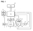
- FIG. 1 shows a structure of a diesel engine, to which the regeneration system of the present embodiment is installed.
- an air intake passage 2 and an exhaust passage 3 are connected to an engine main body 1.
- the air intake passage 2 conducts intake air
- the exhaust passage 3 conducts exhaust gas (emissions) outputted from cylinders of the engine main body 1.
- a diesel particulate filter (DPF) 4 is positioned in the exhaust passage 3.
- the particulate filter 4 includes a porous ceramic body made of, for example, cordierite or silicon carbide.
- the exhaust gas enters the particulate filter 4 through an inlet 4a and passes through partition walls of the porous ceramic body. Thereafter, the exhaust gas exits the particulate filter 4 through an outlet 4b and flows toward a downstream side.
- particulate matter fine exhaust particles (generally referred to as particulate matter) contained in the exhaust gas are captured by the particulate filter 4 and are increasingly accumulated in the particulate filter 4.
- An oxidation catalyst which includes precious metal, such as platinum or palladium, as its major component, is held on a surface of a filter main body of the particulate filter 4 to oxidize, combust and remove the particulate matter under a predetermined temperature condition.
- the diesel engine of the present embodiment includes a fuel supply device, i.e., a fuel injection device 5, which includes injectors for supplying fuel to the cylinders of the engine main body 1. Furthermore, an ECU 6 is provided.
- the ECU 6 controls, for example, the fuel supply amount and fuel injection timing of the fuel injection device 5.
- the ECU 6 performs a control operation for controlling the regeneration operation of the particulate filter 4, which will be described below.
- the ECU 6 plays the central role in the regeneration system for regenerating the particulate filter according to the present embodiment.
- the ECU 6 receives a measurement signal from a differential pressure sensor 8 as a value, which relates to the amount of accumulated particulate matter.
- the differential pressure sensor 8 senses a pressure difference between an upstream side of the particulate filter 4 and a downstream side of the particulate filter 4.
- First and second branched passages 31a, 31b are connected to the exhaust passage 3.
- the first branched passage 31a branches from the exhaust passage 3 on the upstream side of the particulate filter 4, and the second branched passage 31b branches from the exhaust passage 3 on the downstream side of the particulate filter 4.
- the differential pressure sensor 8 senses the pressure difference between the inlet (the upstream side) 4a of the particulate filter 4 and the outlet (the downstream side) 4b of the particulate filter 4.
- the pressure difference which is sensed by the differential pressure sensor 8, correlates to the amount of accumulated particulate matter (hereinafter, referred to as the amount of accumulated PM) of the particulate filter 4.
- the amount of accumulated PM increases to cause an increase in the pressure loss, the pressure difference is also increased.
- a weight sensor 11 is arranged adjacent the particulate filter 4.
- the weight sensor 11 senses the weight of the particulate filter 4 as the value, which relates to the amount of accumulated PM.
- a measurement signal of the weight sensor 11 is also supplied to the ECU 6. It is not required to provide both the differential pressure sensor 8 and the weight sensor 11, and therefore only one of the differential pressure sensor 8 and the weight sensor 11 may be provided, if desired.
- An air flow meter 7 is provided in the air intake passage 2 to sense the flow rate of the intake air (hereinafter, sometimes referred to as an intake air flow rate).
- a measurement signal of the air flow meter 7 is supplied to the ECU 6.
- a measurement signal of an opening degree sensor (also referred to as an accelerator pedal position sensor) 9 and a measurement signal of a crank angle sensor 10 are supplied to the ECU 6.
- the opening degree sensor 9 senses a degree of opening of a throttle valve (not shown), which corresponds to a position of an accelerator pedal (not shown) that is operated by a driver.
- the crank angle sensor 10 senses a rotational speed (rpm) of the engine.
- a diesel oxidation catalyst (DOC) 14 is provided on the downstream side of the particulate filter 4 in the exhaust passage 3.
- the DOC 14 removes harmful exhaust gas components other than the particulate matter.
- an oxygen sensor (O 2 sensor) 13 is provided on the downstream side of the oxidation catalyst 14 to monitor removal of the harmful components by the oxidation catalyst 14. The amount of remaining harmful components in the exhaust gas can be determined by measuring the amount of oxygen in the exhaust gas through the oxygen sensor 13. Alternatively, the amount of harmful components may be directly measured by a gas sensor (not shown).
- a tool (dealer tool) 20 is removably connected to the ECU 6 and commands the ECU 6 to perform the forceful regeneration operation of the particulate filter 4. Furthermore, the tool 20 indicates information about various states in the forceful regeneration operation of the particulate filter 4. The forceful regeneration operation of the particulate filter 4 through use of the tool 20 will be described in greater detail with reference to flow charts shown in FIGS. 2 to 4.
- FIG. 2 shows the flow chart, which indicates a main routine of the forceful regeneration operation of the particulate filter 4.
- step S10 it is determined whether an execution command, which requests execution of the forceful regeneration operation of the particulate filter 4, has been outputted from the tool 20 to the ECU 6.
- step S20 it is determined whether the execution command is outputted from the tool 20 to the ECU 6.
- diagnosis data (sometimes referred to as diag data), which relates to the regeneration operation of the particulate filter 4, is stored, i.e., is present in the ECU 6. More specifically, the ECU 6 monitors the accumulation of the particulate matter in the particulate filter 4 and also monitors whether removal of the particulate matter from the particulate filter 4 can be properly performed during the running state of the diesel engine. When the ECU 6 detects a failure of any component of the regeneration system, the ECU 6 stores the diagnosis data, which includes failure information indicating the failed component and also a type of the failure.
- diagnosis data sometimes referred to as diag data
- an execution time interval for executing the regeneration operation of the particulate filter 4 could be extremely shortened or lengthened.
- the ECU 6 determines that a possibility of failure of the differential pressure sensor 8 is relatively high and stores the corresponding diagnosis data, which indicates the relatively high possibility of the failure of the differential pressure sensor 8.
- step S110 the tool 20 displays failure information, which indicates the failed component, and also displays a message for requesting repair or replacement of the failed component. Furthermore, the tool 20 displays a message for requesting input of a command for executing the forceful regeneration operation of the particulate filter 4 after the repair or the replacement of the failed component. Thereafter, the process ends.
- the regeneration operation may not be properly performed. Thus, in such a failed state, the regeneration operation is prohibited to limit waste of fuel.
- step S30 the amount of accumulated PM of the particulate filter 4 is computed. Then, the corresponding regeneration operating time period (or simply referred to as an operating time period or regeneration time), which corresponds to the computed amount of accumulated PM, is computed. This process will be described in greater detail with reference to FIG. 3.
- step S210 of the flow chart in FIG. 3 a plurality of methods is used to determine the amount of accumulated PM. Thus, a plurality of estimated values for the amount of accumulated PM is obtained. These methods will be described below.
- the maximum value is selected from the estimated values of the amount of accumulated PM, which are computed at step S210.
- the corresponding regeneration operating time period is computed.
- the corresponding regeneration operating time period is the time period required to regenerate the particulate filter 4 by removing the corresponding amount of accumulated PM, which corresponds to the selected maximum value.
- the reason for selecting the maximum value from the estimated values of the amount of accumulated PM at step S220 is to make sure that the particulate matter, which is accumulated in the particulate filter 4 is substantially removed.
- each of the estimated values of the amount of accumulated PM which are computed by the above methods, may be erroneous for some reason.
- the regeneration operating time period can be set based on a sum of a preset value and a weighted average of the amount of accumulated PM. Further alternatively, the regeneration operating time period can be set based on a maximum value that is selected from a group of the average values of the amount of accumulated PM, which fall in a predetermined range.
- the computed regeneration operating time period is displayed by the tool 20 at step S40 of the flow chart shown in FIG. 2. In this way, the operator of the forceful regeneration operation can know the operating time period, which is required to perform the forceful regeneration operation, in advance of the forceful regeneration operation.
- step S50 an engine control operation for the forceful regeneration is performed.
- the engine control operation for the forceful regeneration will be described in greater detail with reference to FIG. 4.
- step S310 the diesel engine is started.
- a multistage fuel injection operation which is performed during the normal operation, is prohibited to reduce the fuel consumption in the forceful regeneration operation. That is, in each combustion stroke, only single fuel injection (main fuel injection) is performed.
- post fuel injection for removing the particulate matter, which is accumulated in the particulate filter 4 is performed.
- the fuel is supplied to the particulate filter 4 by the post fuel injection.
- the temperature of the particulate filter 4 is increased to a sufficient level by the exhaust gas, the fuel is heated and is thus combusted.
- the temperature of the oxidation catalyst of the particulate filter 4 is increased by the combustion heat of the fuel, so that the accumulated particulate matter is combusted and is removed.
- a relay such as an air conditioner relay
- a relay is turned off. This is to prohibit correction of the fuel injection amount caused by turning on of the relay in the forceful regeneration operation. In other words, operation of the air conditioner or the like is not required during the forceful regeneration operation. Thus, each corresponding relay is forcefully turned off to prevent consumption of the excess fuel.
- the fuel injection amount is increased to increase an idling speed of the diesel engine from a normal idling speed to a predetermined idling speed (e.g., about 1500 rpm).
- a predetermined idling speed e.g., about 1500 rpm.
- step S340 it is determined whether the temperature of the particulate filter 4 has been increased to the predetermined temperature, which causes the ignition and combustion of the fuel, based on the measurement signal of the temperature sensor 12. At this time, when it is determined that the temperature of the particulate filter 4 has not bee increased to the predetermined temperature, the increased idling speed of the diesel engine is maintained at step S340. In contrast, when it is determined that the temperature of the particulate filter 4 has been increased to the predetermined temperature, the idling speed of the diesel engine is decreased at step S350. Thus, the increased idling speed is maintained only for a certain time period (a predetermined time period).
- the diesel engine needs to maintain the running state for performing the post fuel injection during the regeneration operation. However, after the particulate filter 4 is heated to the predetermined temperature, which is required for the regeneration operation, it is not required to maintain the high exhaust gas temperature, and it is only required to maintain the idling state of the diesel engine.
- the rotational speed of the diesel engine is controlled to the lowest possible level, i.e., is controlled to the minimum rotational speed (the minimum idling speed) that can maintain the idling state of the diesel engine. In this way, the fuel consumption for maintaining the running state of the diesel engine can be reduced.
- the ECU 6 receives the measurement signals from the differential pressure sensor 8 and the weight sensor 11 at step S60. Then, at step S70, it is determined whether the computed regeneration operating time period, which is computed at step S30, has elapsed.
- a countermeasure against the abnormality is taken at step S90 in such a manner that the tool 20 performs storing of failure information indicating the state of the abnormality and displays information indicating the occurrence of the abnormality.
- the amount of accumulated PM of the particulate filter 4 is estimated before the initiation of the regeneration operation.
- the maximum regeneration operating time period is determined based on the estimated amount of accumulated particulate matter and is set as the regeneration operating time period.
- step S70 when it is determined that the preset regeneration operating time period has not elapsed at step S70, control proceeds to step S80.
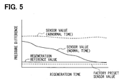
- step S80 it is determined whether the measured sensor value (the measured pressure difference) of the sensor 8 and/or the measured sensor value (measured weight) of the sensor 11 have been reduced to the regeneration reference value or below.
- the sensor value (the measured pressure difference) of the sensor 8 is accordingly progressively reduced.
- the regeneration reference value is set based on a corresponding factory preset sensor value.
- the factory preset sensor value is set under a predetermined operational condition at the time of shipment from a manufacturing factory using a brand-new particulate filter that has no accumulated particulate matter.
- the factory preset sensor value indicates the pressure difference between the inlet and the outlet of the particulate filter, which has no accumulated particulate matter.
- the regeneration reference value can be the factory preset sensor value itself.
- the sensor value obtained based on the measurement signal of the sensor could be held to the high value, which is higher than the regeneration reference value, even after the substantial removal of the particulate matter from the particulate filter 4.
- the countermeasure against the abnormality is taken upon determination of the elapse of the preset regeneration operating time period.
- the differential pressure sensor 8 is described in greater detail above, the sensor value of the weight sensor 11 may be processed in a manner similar to that of the differential pressure sensor 8.
- the regeneration reference value of the weight sensor 11 may be set based on a corresponding factory preset sensor value of the weight sensor 11 or may be the corresponding factory preset sensor value itself.
- the factor preset sensor value of the weight sensor 11 indicates the weight of the particulate filter 4 with no particulate matter.
- step S100 When it is determined that the measured sensor value of the sensor 8 and/or the measured sensor value of the sensor 11 have been reduced to the regeneration reference value or below, control proceeds to step S100.
- step S300 the tool 20 displays completion information indicating the completion of the regeneration operation. Thereafter, control proceeds to step S120 where the diesel engine is stopped, and the forceful regeneration operation is terminated.
- the multiple estimated values of the amount of accumulated PM are computed through the multiple methods.
- only one estimated value of the amount of accumulated PM, which is obtained by one of the above methods, can be used.
- Estimated values of an amount of accumulated particulate matter on a particulate filter (4) are obtained before initiation of a forceful regeneration operation of the particulate filter (4).
- a maximum operating time period of the regeneration operation is set based on the estimated values of the amount of accumulated particulate matter.
- the particulate filter (4) is regenerated in the regeneration operation by performing post fuel injection in the diesel engine during each exhaust stroke of the diesel engine to supply fuel to the particulate filter (4) and thereby to remove the particulate matter from the particulate filter (4) through use of combustion heat of the supplied fuel upon combustion of the supplied fuel.
Landscapes
- Engineering & Computer Science (AREA)
- Chemical & Material Sciences (AREA)
- Combustion & Propulsion (AREA)
- Mechanical Engineering (AREA)
- General Engineering & Computer Science (AREA)
- Processes For Solid Components From Exhaust (AREA)
- Filtering Of Dispersed Particles In Gases (AREA)
- Exhaust Gas Treatment By Means Of Catalyst (AREA)
- Exhaust Gas After Treatment (AREA)
- Electrical Control Of Air Or Fuel Supplied To Internal-Combustion Engine (AREA)
- Combined Controls Of Internal Combustion Engines (AREA)
Abstract
Description
- The present invention relates to regeneration system and method for regenerating a particulate filter, which collects fine exhaust particles (generally referred to as particulate matter) from an exhaust stream of a diesel engine.
- With respect to an internal combustion engine, which is installed in a vehicle, there has been a strong demand for improving a clean level of emissions (exhaust gas) outputted from the engine. Particularly, in a case of a diesel engine, which uses light oil as its fuel, removal of the fine exhaust particles (the particulate matter), such as soot, contained in the exhaust gas is required in addition to removal of CO, HC and NOx from the exhaust gas. To meet such a demand, a particulate filter is arranged in an exhaust passage of the engine to collect the particulate matter from the exhaust gas.
- The particulate filter has, for example, a porous ceramic body. In the particulate filter, when the exhaust gas passes through partition walls of the porous ceramic body, the particulate matter is captured by the partition walls and the pores of the porous ceramic body. When the amount of accumulated particulate matter becomes excessive, the performance of the particulate filter for capturing the particulate matter is disadvantageously lowered, or a flow resistance of the exhaust gas in the particulate filter is disadvantageously increased. When the flow resistance of the exhaust gas is increased, a back pressure of the internal combustion engine is increased to cause a decrease in an output power of the engine. To address such a disadvantage, there is provided a regenerating system for regenerating the particulate filter by appropriately removing the particulate matter, which is accumulated in the particulate filter.
- For example, as recited in Japanese Unexamined Patent Publication No. 2004-1146, post fuel injection is performed to inject fuel during each expansion stroke (or each exhaust stroke) of the diesel engine and thereby to supply the fuel to the particulate filter. Through use of the combustion heat of the supplied fuel, the temperature of the particulate filter is increased, so that the accumulated particulate matter is combusted and is removed.
- Basically, the regeneration operation of the regeneration system is performed in a running state of the diesel engine. More specifically, the regeneration system is operated when the vehicle is driven to travel by the diesel engine. This is true in the regeneration system recited in Japanese Unexamined Patent Publication No. 2004-1146. However, in some cases, a forceful regeneration operation for forcefully regenerating the particulate filter is performed at the time of maintenance service at an automobile dealer without requiring the traveling of the vehicle.
- In the case of the forceful regeneration operation at the automobile dealer, the diesel engine is placed in the running state, and the post fuel injection is performed during each exhaust stroke. The forceful regeneration operation is performed in a manner similar to that of the regeneration operation, which is performed during the traveling of the vehicle. Thus, in some cases, the running state of the diesel engine is not suitable for regenerating the particulate filter, resulting in unnecessary waste of the fuel.
- The present invention addresses the above disadvantage. Thus, it is an objective of the present invention to provide a regeneration system of a particulate filter, which minimizes fuel consumption at time of forceful regeneration of the particulate filter at, for example, an automobile dealer. It is another objective of the present invention to provide a regeneration method of a particulate filter, which minimizes fuel consumption at time of forceful regeneration of the particulate filter at, for example, an automobile dealer.
- To achieve the objectives of the present invention, there is provided a regeneration system for performing a forceful regeneration operation of a particulate filter of a diesel engine installed in a vehicle. The regeneration system includes an estimating means, a setting means, a sensing means, a regenerating means and a stop means. The estimating means is for estimating an amount of accumulated particulate matter on the particulate filter before initiation of the regeneration operation. The estimating means provides at least one estimated value of the amount of accumulated particulate matter. The setting means is for setting a maximum operating time period of the regeneration operation based on the at least one estimated value of the amount of accumulated particulate matter. The sensing means is for sensing at least one physical quantity, which relates to the amount of accumulated particulate matter. The regenerating means is for regenerating the particulate filter in the regeneration operation by performing post fuel injection in the diesel engine during each exhaust stroke of the diesel engine to supply fuel to the particulate filter and thereby to remove the particulate matter from the particulate filter through use of combustion heat of the supplied fuel upon combustion of the supplied fuel. The stop means is for stopping the regeneration operation of the regenerating means when one of the following conditions is satisfied: a remaining amount of accumulated particulate matter of the particulate filter, which is determined based on the at least one physical quantity sensed by the sensing means, is equal to or less than a reference value used to determine completion of regeneration of the particulate filter; and elapsed time, which has been measured since the initiation of the current regeneration operation of the regenerating means, reaches an end of the maximum operating time period.
- In a case where the amount of particulate matter is obtained based on the physical quantity, which is sensed by the sensing means, when a measurement error of the sensing means is excessively large, an exact amount of accumulated particulate matter cannot be obtained. Thus, in such a situation, even after completion of the regeneration of the particulate filter, the running state of the diesel engine may be kept to cause waste of fuel.
- Thus, according to the present invention, the amount of particulate matter is estimated before the initiation of the regeneration operation. Then, the maximum operating time period is set based on at least one estimated value of the amount of accumulated particulate matter. When the elapsed time, which has been measured since the initiation of the current regeneration operation of the regenerating means, reaches the end of the maximum operating time period, the regeneration operation is forcefully stopped. Thus, even when the measurement error of the sensing means is relatively large, it is possible to limit waste of the fuel.
- The regeneration system of the present invention may further include a failure diagnosing means and a storage means. The failure diagnosing means is for diagnosing a failure of at least one of the estimating means, the setting means, the sensing means, the regenerating means and the stop means. The storage means is for storing failure information when the failure of any one of the at least one of the estimating means, the setting means, the sensing means, the regenerating means and the stop means is sensed by the failure diagnosing means. The failure information is indicative of the sensed failure. The stop means may stop the regeneration operation of the regenerating means when the failure information is present in the storage means. When one component of the regeneration system fails, the regeneration operation may not be properly performed. Thus, in such a situation, the regeneration operation is stopped to limit waste of the fuel.
- In the above regeneration system, the at least one estimated value of the amount of accumulated particulate matter, which is estimated by the estimating means, may include a plurality of estimated values of the amount of accumulated particulate matter. The estimating means may estimate the plurality of estimated values of the amount of accumulated particulate matter through a plurality of methods, respectively. The setting means may set the maximum operating time period of the regeneration operation based on the plurality of estimated values of the amount of accumulated particulate matter. In this way, the maximum operating time period can be set to correspond with the more accurate amount of accumulated particulate matter. In the case where the maximum operating time period is determined based on the multiple estimated values of the amount of accumulated particulate matter, the maximum operating time period may be determined based on an average (weighted average) of the estimated values of the amount of accumulated particulate matter. Alternatively, the maximum operating time period may be determined based on a sum of a preset value and the average (weighted average) of the estimated values. Further alternatively, the maximum operating time period may be determined based on a maximum value of a group of the estimated values, which fall within a predetermined range.
- However, in order to substantially remove the particulate matter from the particulate filter, the setting means may set the maximum operating time period of the regeneration operation based on a maximum one of the plurality of estimated values of the amount of accumulated particulate matter.
- The plurality of estimated values of the amount of accumulated particulate matter, which are estimated by the estimating means, may include at least two of: an estimated value of the amount of accumulated particulate matter that is estimated by the estimating means based on a pressure difference between an inlet of the particulate filter and an outlet of the particulate filter; an estimated value of the amount of accumulated particulate matter that is estimated by the estimating means based on a weight of the particulate filter; an estimated value of the amount of accumulated particulate matter that is estimated by the estimating means based on elapsed operating time of the diesel engine, which has been measured since an end of a previous forceful regeneration operation of the particulate filter; an estimated value of the amount of accumulated particulate matter that is estimated by the estimating means based on a travel distance of the vehicle, which has been measured since the end of the previous regeneration operation of the particulate filter; and an estimated value of the amount of accumulated particulate matter that is estimated by the estimating means based on a total amount of injected fuel, which has been measured since the end of the previous regeneration operation of the particulate filter.
- The regeneration system may include a rotational speed control means for controlling a rotational speed of the diesel engine. The rotational speed control means keeps the rotational speed of the diesel engine higher than a normal idling speed of the diesel engine throughout a predetermined time period, which starts at time of the initiation of the current regeneration operation. In this way, an increase rate of the temperature of the particulate filter is increased. Thus, the removal of the particulate matter (regeneration of the particulate filter) through the combustion of the supplied fuel, which is supplied by the post fuel injection, can be accelerated. This may result in a decrease in the fuel consumption.
- The predetermined time period may end when combustion of the supplied fuel, which is supplied to the particulate filter, is confirmed. When the combustion of the supplied fuel is confirmed, it is assumed that the particulate filter has been heated to the predetermined temperature, which is required for the regeneration operation.
- The rotational speed control means may reduce the rotational speed of the diesel engine to a minimum idling speed, which is required for maintaining the idling of the diesel engine, after elapse of the predetermined time period. During the regeneration operation, the diesel engine needs to be kept running to perform the post fuel injection. Thus, after the particulate filter is heated to the predetermined temperature, the rotational speed is maintained at the minimum rotational speed to minimize the fuel consumption.
- The rotational speed control means may control the rotational speed of the diesel engine in such a manner that single fuel injection is performed in the diesel engine per combustion stroke of the diesel engine throughout the regeneration operation of the regenerating means.
- In the diesel engine, multistage fuel injection operation (for example, including pilot fuel injection, pre-fuel injection, main fuel injection and after fuel injection) is often performed to increase the combustion temperature of the fuel to achieve appropriate combustion of the fuel. However, in order to reduce the fuel consumption, the multistage fuel injection operation should be prohibited, and the single fuel injection (e.g., the main fuel injection) may be performed during the combustion stroke.
- Furthermore, to achieve the objectives of the present invention, there is also provided a regeneration method for regenerating a particulate filter of a diesel engine installed in a vehicle. This method may be performed, for example, at an automobile dealer without requiring traveling of the vehicle. According to the method, at least one estimated value of an amount of accumulated particulate matter on the particulate filter is obtained before initiation of a forceful regeneration operation of the particulate filter. A maximum operating time period of the regeneration operation is set based on the at least one estimated value of the amount of accumulated particulate matter. The particulate filter is regenerated in the regeneration operation by performing post fuel injection in the diesel engine during each exhaust stroke of the diesel engine to supply fuel to the particulate filter and thereby to remove the particulate matter from the particulate filter through use of combustion heat of the supplied fuel upon combustion of the supplied fuel. Then, the regeneration operation is stopped when one of the following conditions is satisfied: a remaining amount of accumulated particulate matter of the particulate filter is equal to or less than a reference value used to determine completion of regeneration of the particulate filter; and elapsed time, which has been measured since the initiation of the current regeneration operation, reaches an end of the maximum operating time period.
- The invention, together with additional objectives, features and advantages thereof, will be best understood from the following description, the appended claims and the accompanying drawings in which:
- FIG. 1 is a diagram showing a structure of a diesel engine, to which a regeneration system for regenerating a particulate filter according to an embodiment of the present invention is applied;
- FIG. 2 is a flow chart, which indicates a main routine of a forceful regeneration operation of the particulate filter by the regeneration system;
- FIG. 3 is a flow chart showing an operation for computing an amount of accumulated particulate matter of the particulate filter and for computing a regeneration operating time period, which corresponds to the computed amount of accumulated particulate matter;
- FIG. 4 is a flow chart showing an engine control operation during the forceful regeneration of the particulate filter; and
- FIG. 5 is a sensor characteristic diagram showing characteristics of a differential pressure sensor of the regeneration system.
-
- Regeneration system and method for regenerating a particulate filter according to an embodiment of the present invention will be described with reference to the accompanying drawings.
- FIG. 1 shows a structure of a diesel engine, to which the regeneration system of the present embodiment is installed. In the diesel engine, an
air intake passage 2 and anexhaust passage 3 are connected to an enginemain body 1. Theair intake passage 2 conducts intake air, and theexhaust passage 3 conducts exhaust gas (emissions) outputted from cylinders of the enginemain body 1. Furthermore, a diesel particulate filter (DPF) 4 is positioned in theexhaust passage 3. Theparticulate filter 4 includes a porous ceramic body made of, for example, cordierite or silicon carbide. The exhaust gas enters theparticulate filter 4 through aninlet 4a and passes through partition walls of the porous ceramic body. Thereafter, the exhaust gas exits theparticulate filter 4 through anoutlet 4b and flows toward a downstream side. At this time, fine exhaust particles (generally referred to as particulate matter) contained in the exhaust gas are captured by theparticulate filter 4 and are increasingly accumulated in theparticulate filter 4. An oxidation catalyst, which includes precious metal, such as platinum or palladium, as its major component, is held on a surface of a filter main body of theparticulate filter 4 to oxidize, combust and remove the particulate matter under a predetermined temperature condition. - The diesel engine of the present embodiment includes a fuel supply device, i.e., a
fuel injection device 5, which includes injectors for supplying fuel to the cylinders of the enginemain body 1. Furthermore, anECU 6 is provided. TheECU 6 controls, for example, the fuel supply amount and fuel injection timing of thefuel injection device 5. In addition to the control operation for controlling the operational state of the diesel engine, theECU 6 performs a control operation for controlling the regeneration operation of theparticulate filter 4, which will be described below. Thus, theECU 6 plays the central role in the regeneration system for regenerating the particulate filter according to the present embodiment. - Various signals, which indicate the actual operational state of the diesel engine, are supplied to the
ECU 6. The diesel engine is controlled based on these signals to achieve a desired operational state of the diesel engine. - First, the
ECU 6 receives a measurement signal from adifferential pressure sensor 8 as a value, which relates to the amount of accumulated particulate matter. Thedifferential pressure sensor 8 senses a pressure difference between an upstream side of theparticulate filter 4 and a downstream side of theparticulate filter 4. First and secondbranched passages exhaust passage 3. The firstbranched passage 31a branches from theexhaust passage 3 on the upstream side of theparticulate filter 4, and the secondbranched passage 31b branches from theexhaust passage 3 on the downstream side of theparticulate filter 4. Thedifferential pressure sensor 8 senses the pressure difference between the inlet (the upstream side) 4a of theparticulate filter 4 and the outlet (the downstream side) 4b of theparticulate filter 4. The pressure difference, which is sensed by thedifferential pressure sensor 8, correlates to the amount of accumulated particulate matter (hereinafter, referred to as the amount of accumulated PM) of theparticulate filter 4. When the amount of accumulated PM increases to cause an increase in the pressure loss, the pressure difference is also increased. - Furthermore, a
weight sensor 11 is arranged adjacent theparticulate filter 4. Theweight sensor 11 senses the weight of theparticulate filter 4 as the value, which relates to the amount of accumulated PM. A measurement signal of theweight sensor 11 is also supplied to theECU 6. It is not required to provide both thedifferential pressure sensor 8 and theweight sensor 11, and therefore only one of thedifferential pressure sensor 8 and theweight sensor 11 may be provided, if desired. - An
air flow meter 7 is provided in theair intake passage 2 to sense the flow rate of the intake air (hereinafter, sometimes referred to as an intake air flow rate). A measurement signal of theair flow meter 7 is supplied to theECU 6. Also, a measurement signal of an opening degree sensor (also referred to as an accelerator pedal position sensor) 9 and a measurement signal of acrank angle sensor 10 are supplied to theECU 6. Theopening degree sensor 9 senses a degree of opening of a throttle valve (not shown), which corresponds to a position of an accelerator pedal (not shown) that is operated by a driver. Thecrank angle sensor 10 senses a rotational speed (rpm) of the engine. - Furthermore, a diesel oxidation catalyst (DOC) 14 is provided on the downstream side of the
particulate filter 4 in theexhaust passage 3. TheDOC 14 removes harmful exhaust gas components other than the particulate matter. Furthermore, an oxygen sensor (O2 sensor) 13 is provided on the downstream side of theoxidation catalyst 14 to monitor removal of the harmful components by theoxidation catalyst 14. The amount of remaining harmful components in the exhaust gas can be determined by measuring the amount of oxygen in the exhaust gas through theoxygen sensor 13. Alternatively, the amount of harmful components may be directly measured by a gas sensor (not shown). - A tool (dealer tool) 20 is removably connected to the
ECU 6 and commands theECU 6 to perform the forceful regeneration operation of theparticulate filter 4. Furthermore, thetool 20 indicates information about various states in the forceful regeneration operation of theparticulate filter 4. The forceful regeneration operation of theparticulate filter 4 through use of thetool 20 will be described in greater detail with reference to flow charts shown in FIGS. 2 to 4. - FIG. 2 shows the flow chart, which indicates a main routine of the forceful regeneration operation of the
particulate filter 4. As shown in FIG. 2, first, at step S10, it is determined whether an execution command, which requests execution of the forceful regeneration operation of theparticulate filter 4, has been outputted from thetool 20 to theECU 6. When it is determined that the execution command is outputted from thetool 20 to theECU 6, control proceeds to step S20. - At step S20, it is determined whether diagnosis data (sometimes referred to as diag data), which relates to the regeneration operation of the
particulate filter 4, is stored, i.e., is present in theECU 6. More specifically, theECU 6 monitors the accumulation of the particulate matter in theparticulate filter 4 and also monitors whether removal of the particulate matter from theparticulate filter 4 can be properly performed during the running state of the diesel engine. When theECU 6 detects a failure of any component of the regeneration system, theECU 6 stores the diagnosis data, which includes failure information indicating the failed component and also a type of the failure. - For example, in a case where the
differential pressure sensor 8 is failed, and thereby the amount of accumulated particulate matter cannot be correctly sensed, an execution time interval for executing the regeneration operation of theparticulate filter 4 could be extremely shortened or lengthened. In such a case, theECU 6 determines that a possibility of failure of thedifferential pressure sensor 8 is relatively high and stores the corresponding diagnosis data, which indicates the relatively high possibility of the failure of thedifferential pressure sensor 8. - When it is determined that the diagnosis data is stored in the
ECU 6 at step S20, control proceeds to step S110 . At step S110, thetool 20 displays failure information, which indicates the failed component, and also displays a message for requesting repair or replacement of the failed component. Furthermore, thetool 20 displays a message for requesting input of a command for executing the forceful regeneration operation of theparticulate filter 4 after the repair or the replacement of the failed component. Thereafter, the process ends. In a case where the one of the components of the regeneration system is failed, the regeneration operation may not be properly performed. Thus, in such a failed state, the regeneration operation is prohibited to limit waste of fuel. - In contrast, when it is determined that the diagnosis data is not stored in the
ECU 6 at step S20, control proceeds to step S30. At step S30, the amount of accumulated PM of theparticulate filter 4 is computed. Then, the corresponding regeneration operating time period (or simply referred to as an operating time period or regeneration time), which corresponds to the computed amount of accumulated PM, is computed. This process will be described in greater detail with reference to FIG. 3. - First, at step S210 of the flow chart in FIG. 3, a plurality of methods is used to determine the amount of accumulated PM. Thus, a plurality of estimated values for the amount of accumulated PM is obtained. These methods will be described below.
- (1) The diesel engine is started and is thus placed in the
running state. Then, the amount of accumulated PM is estimated
based on the pressure difference between the
inlet 4a and theoutlet 4b of theparticulate filter 4 at the time of supplying the predetermined intake air flow. - (2) The weight of the
particulate filter 4 is sensed through theweight sensor 11, and the amount of accumulated PM is estimated based on the sensed weight of theparticulate filter 4. When the amount of accumulated PM is increased, the weight of theparticulate filter 4 is accordingly increased. Based on a change in the weight of theparticulate filter 4, the amount of accumulated PM can be estimated. - (3) An operating time period of the diesel engine between the end of the previous regeneration operation and the beginning of the current regeneration operation is measured every time the regeneration operation is performed. The amount of accumulated PM is estimated based on an average of the operating time period of the diesel engine between the two consecutive regeneration operations during the normal operation. In the normal operation, when the amount of accumulated PM reaches a regeneration reference value (a threshold value) for initiating the regeneration operation, the regeneration operation is executed. Thus, by storing the average of the operating time period of the diesel engine between the two consecutive regeneration operations, the amount of accumulated PM can be estimated based on a ratio of the current elapsed regeneration time, which has been measured since the end of the previous regeneration operation, relative to the average of the operating time period of the diesel engine between the two consecutive regeneration operations. Alternatively, the amount of accumulated PM per unit time during the normal operation may be computed. Then, the total amount of accumulated PM may be estimated by multiplying the amount of accumulated PM per unit time by the current elapsed regeneration time of the diesel engine.
- (4) A travel distance of the vehicle having the diesel engine between the end of the previous regeneration operation and the beginning of the current regeneration operation is measured every time the regeneration operation is performed. The amount of accumulated PM is estimated based on an average of the travel distance of the vehicle between the two consecutive regeneration operations during the normal operation. That is, similar to the above case where the operating time period of the diesel engine is used to estimate the amount of accumulated PM, the amount of accumulated PM can be estimated based on a ratio of the current travel distance of the vehicle, which has been measured since the end of the previous regeneration operation, relative to the average of the travel distance of the vehicle.
- (5) The total amount of injected fuel in the diesel engine between the end of the previous regeneration operation and the beginning of the current regeneration operation is measured every time the regeneration operation is performed. The amount of accumulated PM is estimated based on an average of the total amount of injected fuel between the two consecutive regeneration operations during the normal operation. That is, the average of the total amount of injected fuel, which is injected between the two consecutive regeneration operations, is stored. Then, the amount of accumulated PM can be estimated based on a ratio of the current cumulative amount of injected fuel, which has been injected since the end of the previous regeneration operation, relative to the average of the total amount of injected fuel.
- (6) The diesel engine is started and is thus placed in the
predetermined running state. Then, the amount of accumulated PM
is estimated based on a gradient of a change in the pressure
difference between the
inlet 4a and theoutlet 4b of theparticulate filter 4 in the predetermined running state. That is, the gradient of the change in the pressure difference measured by thedifferential pressure sensor 8 is not always constant. More specifically, the gradient of the change in the pressure difference measured by thedifferential pressure sensor 8 changes quadratically according to the amount of accumulated PM. Thus, the amount of accumulated PM can be estimated based on the gradient of the change in the pressure difference. -
- Next, at step S220, the maximum value is selected from the estimated values of the amount of accumulated PM, which are computed at step S210. Then, at step S230, the corresponding regeneration operating time period is computed. The corresponding regeneration operating time period is the time period required to regenerate the
particulate filter 4 by removing the corresponding amount of accumulated PM, which corresponds to the selected maximum value. - The reason for selecting the maximum value from the estimated values of the amount of accumulated PM at step S220 is to make sure that the particulate matter, which is accumulated in the
particulate filter 4 is substantially removed. However, it should be noted that each of the estimated values of the amount of accumulated PM, which are computed by the above methods, may be erroneous for some reason. Thus, alternative to the use of the selected maximum value, the regeneration operating time period can be set based on a sum of a preset value and a weighted average of the amount of accumulated PM. Further alternatively, the regeneration operating time period can be set based on a maximum value that is selected from a group of the average values of the amount of accumulated PM, which fall in a predetermined range. - When the computation of the regeneration operating time period ends, the computed regeneration operating time period is displayed by the
tool 20 at step S40 of the flow chart shown in FIG. 2. In this way, the operator of the forceful regeneration operation can know the operating time period, which is required to perform the forceful regeneration operation, in advance of the forceful regeneration operation. - At step S50, an engine control operation for the forceful regeneration is performed. The engine control operation for the forceful regeneration will be described in greater detail with reference to FIG. 4.
- First, at step S310, the diesel engine is started. At this time, a multistage fuel injection operation, which is performed during the normal operation, is prohibited to reduce the fuel consumption in the forceful regeneration operation. That is, in each combustion stroke, only single fuel injection (main fuel injection) is performed.
- Furthermore, in each exhaust stroke, post fuel injection for removing the particulate matter, which is accumulated in the
particulate filter 4, is performed. The fuel is supplied to theparticulate filter 4 by the post fuel injection. When the temperature of theparticulate filter 4 is increased to a sufficient level by the exhaust gas, the fuel is heated and is thus combusted. In the regeneration operation, the temperature of the oxidation catalyst of theparticulate filter 4 is increased by the combustion heat of the fuel, so that the accumulated particulate matter is combusted and is removed. - Next, at step S320, a relay, such as an air conditioner relay, is turned off. This is to prohibit correction of the fuel injection amount caused by turning on of the relay in the forceful regeneration operation. In other words, operation of the air conditioner or the like is not required during the forceful regeneration operation. Thus, each corresponding relay is forcefully turned off to prevent consumption of the excess fuel.
- At step S330, the fuel injection amount is increased to increase an idling speed of the diesel engine from a normal idling speed to a predetermined idling speed (e.g., about 1500 rpm). As described above, in the
particulate filter 4, the removal of the particulate matter is possible only when the fuel is heated by the exhaust gas to its ignition temperature. The increase in the temperature of theparticulate filter 4 can be further enhanced or accelerated by increasing the idling speed of the diesel engine. In this way, the removal of the particulate matter, i.e., the regeneration of theparticulate filter 4 can be accelerated by the combustion of the fuel supplied in the post fuel injection. As a result, the required total fuel injection amount, which is required in the entire regeneration operation, can be reduced. - At step S340, it is determined whether the temperature of the
particulate filter 4 has been increased to the predetermined temperature, which causes the ignition and combustion of the fuel, based on the measurement signal of thetemperature sensor 12. At this time, when it is determined that the temperature of theparticulate filter 4 has not bee increased to the predetermined temperature, the increased idling speed of the diesel engine is maintained at step S340. In contrast, when it is determined that the temperature of theparticulate filter 4 has been increased to the predetermined temperature, the idling speed of the diesel engine is decreased at step S350. Thus, the increased idling speed is maintained only for a certain time period (a predetermined time period). - The diesel engine needs to maintain the running state for performing the post fuel injection during the regeneration operation. However, after the
particulate filter 4 is heated to the predetermined temperature, which is required for the regeneration operation, it is not required to maintain the high exhaust gas temperature, and it is only required to maintain the idling state of the diesel engine. Thus, the rotational speed of the diesel engine is controlled to the lowest possible level, i.e., is controlled to the minimum rotational speed (the minimum idling speed) that can maintain the idling state of the diesel engine. In this way, the fuel consumption for maintaining the running state of the diesel engine can be reduced. - During the engine control operation, which is performed in the forceful regeneration, the
ECU 6 receives the measurement signals from thedifferential pressure sensor 8 and theweight sensor 11 at step S60. Then, at step S70, it is determined whether the computed regeneration operating time period, which is computed at step S30, has elapsed. - When the regeneration operating time period elapses before the amount of accumulated PM, which is sensed based on the measurement signal of the
differential pressure sensor 8 and/or the measurement signal of theweight sensor 11, reaches the regeneration reference value, which indicates the completion of the regeneration of theparticulate filter 4, it could be caused by an abnormality, such as the sensor failure. Thus, a countermeasure against the abnormality is taken at step S90 in such a manner that thetool 20 performs storing of failure information indicating the state of the abnormality and displays information indicating the occurrence of the abnormality. - According to the present embodiment, as discussed above, even when the correct amount of accumulated PM of the
particulate filter 4 cannot be measured due to the occurrence of the abnormality, such as the failure of thedifferential pressure sensor 8, the amount of accumulated PM of theparticulate filter 4 is estimated before the initiation of the regeneration operation. The maximum regeneration operating time period is determined based on the estimated amount of accumulated particulate matter and is set as the regeneration operating time period. Thus, when the elapsed time, which has been measured since the beginning of the regeneration operation, reaches the end of the preset regeneration operating time period, the regeneration operation can be forcefully terminated to avoid waste of the fuel. - In contrast, when it is determined that the preset regeneration operating time period has not elapsed at step S70, control proceeds to step S80. At step S80, it is determined whether the measured sensor value (the measured pressure difference) of the
sensor 8 and/or the measured sensor value (measured weight) of thesensor 11 have been reduced to the regeneration reference value or below. - In the case of the
differential pressure 8, as shown in the characteristic diagram of FIG. 5, when thesensor 8 is normal, the particulate matter is continuously removed by the forceful regeneration operation. Therefore, the sensor value (the measured pressure difference) of thesensor 8 is accordingly progressively reduced. When the sensor value is reduced and becomes equal to or less than the regeneration reference value, it is determined that the regeneration of theparticulate filter 4 is completed. Here, the regeneration reference value is set based on a corresponding factory preset sensor value. The factory preset sensor value is set under a predetermined operational condition at the time of shipment from a manufacturing factory using a brand-new particulate filter that has no accumulated particulate matter. Therefore, the factory preset sensor value indicates the pressure difference between the inlet and the outlet of the particulate filter, which has no accumulated particulate matter. Alternatively, the regeneration reference value can be the factory preset sensor value itself. When the sensor is abnormal, the sensor value obtained based on the measurement signal of the sensor could be held to the high value, which is higher than the regeneration reference value, even after the substantial removal of the particulate matter from theparticulate filter 4. In such a case, the countermeasure against the abnormality is taken upon determination of the elapse of the preset regeneration operating time period. Although thedifferential pressure sensor 8 is described in greater detail above, the sensor value of theweight sensor 11 may be processed in a manner similar to that of thedifferential pressure sensor 8. That is, when the sensor value of theweight sensor 11 is reduced and becomes equal to or less than the corresponding regeneration reference value, it is determined that the regeneration of theparticulate filter 4 is completed. Like thedifferential pressure sensor 8, the regeneration reference value of theweight sensor 11 may be set based on a corresponding factory preset sensor value of theweight sensor 11 or may be the corresponding factory preset sensor value itself. The factor preset sensor value of theweight sensor 11 indicates the weight of theparticulate filter 4 with no particulate matter. - When it is determined that the measured sensor value of the
sensor 8 and/or the measured sensor value of thesensor 11 have been reduced to the regeneration reference value or below, control proceeds to step S100. At step S300, thetool 20 displays completion information indicating the completion of the regeneration operation. Thereafter, control proceeds to step S120 where the diesel engine is stopped, and the forceful regeneration operation is terminated. - The preferred embodiment of the present invention has been described. However, the regeneration system of the present invention is not limited to the above embodiment and can be embodied in other various forms.
- For example, in the above embodiment, the multiple estimated values of the amount of accumulated PM are computed through the multiple methods. Alternatively, only one estimated value of the amount of accumulated PM, which is obtained by one of the above methods, can be used.
- Additional advantages and modifications will readily occur to those skilled in the art. The invention in its broader terms is therefore not limited to the specific details, representative apparatus, and illustrative examples shown and described.
- Estimated values of an amount of accumulated particulate matter on a particulate filter (4) are obtained before initiation of a forceful regeneration operation of the particulate filter (4). A maximum operating time period of the regeneration operation is set based on the estimated values of the amount of accumulated particulate matter. The particulate filter (4) is regenerated in the regeneration operation by performing post fuel injection in the diesel engine during each exhaust stroke of the diesel engine to supply fuel to the particulate filter (4) and thereby to remove the particulate matter from the particulate filter (4) through use of combustion heat of the supplied fuel upon combustion of the supplied fuel.
Claims (18)
- A regeneration system for performing a forceful regeneration operation of a particulate filter (4) of a diesel engine installed in a vehicle, the regeneration system being characterized by:an estimating means (S30) for estimating an amount of accumulated particulate matter on the particulate filter (4) before initiation of the regeneration operation, wherein the estimating means (S30) provides at least one estimated value of the amount of accumulated particulate matter;a setting means (S30) for setting a maximum operating time period of the regeneration operation based on the at least one estimated value of the amount of accumulated particulate matter;a sensing means (S60) for sensing at least one physical quantity, which relates to the amount of accumulated particulate matter;a regenerating means (S50) for regenerating the particulate filter (4) in the regeneration operation by performing post fuel injection in the diesel engine during each exhaust stroke of the diesel engine to supply fuel to the particulate filter (4) and thereby to remove the particulate matter from the particulate filter (4) through use of combustion heat of the supplied fuel upon combustion of the supplied fuel; anda stop means (S80, S100, S120) for stopping the regeneration operation of the regenerating means (S50) when one of the following conditions is satisfied:a remaining amount of accumulated particulate matter of the particulate filter (4), which is determined based on the at least one physical quantity sensed by the sensing means (S60), is equal to or less than a reference value used to determine completion of regeneration of the particulate filter (4); andelapsed time, which has been measured since the initiation of the current regeneration operation of the regenerating means (S50), reaches an end of the maximum operating time period.
- The regeneration system according to claim 1, further characterized by:a failure diagnosing means (S20) for diagnosing a failure of at least one of the estimating means (S30), the setting means (S30), the sensing means (S60), the regenerating means (S50) and the stop means (S80, S100, S120); anda storage means (6) for storing failure information when the failure of any one of the at least one of the estimating means (S30), the setting means (S30), the sensing means (S60), the regenerating means (S50) and the stop means (S80, S100, S120) is sensed by the failure diagnosing means (S20), wherein:the failure information is indicative of the sensed failure; andthe stop means (S80, S100, S120) stops the regeneration operation of the regenerating means (S50) when the failure information is present in the storage means (6).
- The regeneration system according to claim 1 or 2, characterized in that:the at least one estimated value of the amount of accumulated particulate matter, which is estimated by the estimating means (S30), includes a plurality of estimated values of the amount of accumulated particulate matter;the estimating means (S30) estimates the plurality of estimated values of the amount of accumulated particulate matter through a plurality of methods, respectively; andthe setting means (S30) sets the maximum operating time period of the regeneration operation based on the plurality of estimated values of the amount of accumulated particulate matter.
- The regeneration system according to claim 3, characterized in that the setting means (S30) sets the maximum operating time period of the regeneration operation based on a maximum one of the plurality of estimated values of the amount of accumulated particulate matter.
- The regeneration system according to claim 3 or 4, characterized in that the plurality of estimated values of the amount of accumulated particulate matter, which are estimated by the estimating means (S30), includes at least two of:an estimated value of the amount of accumulated particulate matter that is estimated by the estimating means (S30) based on a pressure difference between an inlet (4a) of the particulate filter (4) and an outlet (4b) of the particulate filter (4);an estimated value of the amount of accumulated particulate matter that is estimated by the estimating means (S30) based on a weight of the particulate filter (4);an estimated value of the amount of accumulated particulate matter that is estimated by the estimating means (S30) based on elapsed operating time of the diesel engine, which has been measured since an end of a previous forceful regeneration operation of the particulate filter (4);an estimated value of the amount of accumulated particulate matter that is estimated by the estimating means (S30) based on a travel distance of the vehicle, which has been measured since the end of the previous regeneration operation of the particulate filter (4); andan estimated value of the amount of accumulated particulate matter that is estimated by the estimating means (S30) based on a total amount of injected fuel, which has been measured since the end of the previous regeneration operation of the particulate filter (4).
- The regeneration system according to any one of claims 1 to 5, further characterized by a rotational speed control means (S50) for controlling a rotational speed of the diesel engine, wherein the rotational speed control means (S50) keeps the rotational speed of the diesel engine higher than a normal idling speed of the diesel engine throughout a predetermined time period, which starts at time of the initiation of the current regeneration operation.
- The regeneration system according to claim 6, characterized in that the predetermined time period ends when combustion of the supplied fuel, which is supplied to the particulate filter (4), is confirmed.
- The regeneration system according to claim 6 or 7, characterized in that the rotational speed control means (S50) reduces the rotational speed of the diesel engine to a minimum idling speed, which is required for maintaining the idling of the diesel engine, after elapse of the predetermined time period.
- The regeneration system according to any one of claims 6 to 8, characterized in that the rotational speed control means (S50) controls the rotational speed of the diesel engine in such a manner that single fuel injection is performed in the diesel engine per combustion stroke of the diesel engine throughout the regeneration operation of the regenerating means (S50).
- A regeneration method for regenerating a particulate filter (4) of a diesel engine installed in a vehicle, the regeneration method being characterized by:obtaining at least one estimated value of an amount of accumulated particulate matter on the particulate filter (4) before initiation of a forceful regeneration operation of the particulate filter (4);setting a maximum operating time period of the regeneration operation based on the at least one estimated value of the amount of accumulated particulate matter;regenerating the particulate filter (4) in the regeneration operation by performing post fuel injection in the diesel engine during each exhaust stroke of the diesel engine to supply fuel to the particulate filter (4) and thereby to remove the particulate matter from the particulate filter (4) through use of combustion heat of the supplied fuel upon combustion of the supplied fuel; andstopping the regeneration operation when one of the following conditions is satisfied:a remaining amount of accumulated particulate matter of the particulate filter (4) is equal to or less than a reference value used to determine completion of regeneration of the particulate filter (4); andelapsed time, which has been measured since the initiation of the current regeneration operation, reaches an end of the maximum operating time period.
- The regeneration method according to claim 10, further characterized by:diagnosing a failure of at least one component of a regeneration system; andstoring failure information in a storage means (6) when the failure is sensed in the diagnosing of the failure, wherein:the failure information is indicative of the sensed failure; andthe stopping of the regeneration operation includes stopping the regeneration operation when the failure information is present in the storage means (6).
- The regeneration method according to claim 10 or 11, characterized in that:the obtaining of the at least one estimated value of the amount of accumulated particulate matter includes obtaining a plurality of estimated values of the amount of accumulated particulate matter through a plurality of methods, respectively; andthe setting of the maximum operating time period includes setting the maximum operating time period based on the plurality of estimated values of the amount of accumulated particulate matter.
- The regeneration method according to claim 12, characterized in that the setting of the maximum operating time period includes setting the maximum operating time period based on a maximum one of the plurality of estimated values of the amount of accumulated particulate matter.
- The regeneration method according to claim 12 or 13, characterized in that the obtaining of the plurality of estimated values of the amount of accumulated particulate matter includes obtaining at least two of:an estimated value of the amount of accumulated particulate matter that is estimated based on a pressure difference between an inlet (4a) of the particulate filter (4) and an outlet (4b) of the particulate filter (4);an estimated value of the amount of accumulated particulate matter that is estimated based on a weight of the particulate filter (4);an estimated value of the amount of accumulated particulate matter that is estimated based on elapsed operating time of the diesel engine, which has been measured since an end of a previous forceful regeneration operation of the particulate filter (4);an estimated value of the amount of accumulated particulate matter that is estimated based on a travel distance of the vehicle, which has been measured since the end of the previous regeneration operation of the particulate filter (4); andan estimated value of the amount of accumulated particulate matter that is estimated based on a total amount of injected fuel, which has been measured since the end of the previous regeneration operation of the particulate filter (4).
- The regeneration method according to any one of claims 10 to 14, characterized in that the regenerating of the particulate filter (4) includes keeping a rotational speed of the diesel engine higher than a normal idling speed of the diesel engine throughout a predetermined time period, which starts at time of initiation of the current regeneration operation.
- The regeneration method according to claim 15, characterized in that the predetermined time period ends when combustion of the supplied fuel, which is supplied to the particulate filter (4), is confirmed.
- The regeneration method according to claim 16, characterized in that the regenerating of the particulate filter (4) includes reducing the rotational speed of the diesel engine to a minimum idling speed, which is required for maintaining the idling of the diesel engine, after elapse of the predetermined time period.
- The regeneration method according to any one of claims 15 to 17, characterized in that the regenerating of the particulate filter (4) includes performing single fuel injection in the diesel engine per combustion stroke of the diesel engine through an entire period of the regenerating of the particulate filter (4).
Applications Claiming Priority (2)
| Application Number | Priority Date | Filing Date | Title |
|---|---|---|---|
| JP2004104813A JP4221592B2 (en) | 2004-03-31 | 2004-03-31 | Particulate filter regeneration processing device |
| JP2004104813 | 2004-03-31 |
Publications (2)
| Publication Number | Publication Date |
|---|---|
| EP1582714A1 true EP1582714A1 (en) | 2005-10-05 |
| EP1582714B1 EP1582714B1 (en) | 2006-09-27 |
Family
ID=34880058
Family Applications (1)
| Application Number | Title | Priority Date | Filing Date |
|---|---|---|---|
| EP05007108A Expired - Lifetime EP1582714B1 (en) | 2004-03-31 | 2005-03-31 | Regeneration system and method for regenerating particulate filter |
Country Status (3)
| Country | Link |
|---|---|
| EP (1) | EP1582714B1 (en) |
| JP (1) | JP4221592B2 (en) |
| DE (1) | DE602005000146T2 (en) |
Cited By (12)
| Publication number | Priority date | Publication date | Assignee | Title |
|---|---|---|---|---|
| WO2008021816A3 (en) * | 2006-08-16 | 2008-04-03 | Int Engine Intellectual Prop | Strategy for using exhaust stroke post-injection to elevate exhaust temperature for diesel particulate filter regeneration |
| EP1975396A1 (en) * | 2007-03-06 | 2008-10-01 | Toyota Jidosha Kabushiki Kaisha | Control apparatus and control method for diesel vehicle |
| US20100089041A1 (en) * | 2007-05-01 | 2010-04-15 | Chun Tai | Method and arrangement for maintaining a diesel particulate filter in a diesel engine exhaust system |
| US8050844B2 (en) | 2008-03-21 | 2011-11-01 | Ford Global Technologies, Llc | Pre-delivery strategy for diesel-engine vehicles |
| EP2390480A1 (en) * | 2010-05-25 | 2011-11-30 | Honda Motor Co., Ltd. | Exhaust purification system for internal combustion engine |
| GB2496876A (en) * | 2011-11-24 | 2013-05-29 | Ford Global Tech Llc | Controlling soot burn in a diesel particulate filter (DPF) of a vehicle |
| US8584446B2 (en) | 2008-08-08 | 2013-11-19 | Pirelli & C. Eco Technology S.P.A. | Method and device for controlling the regeneration of a particulate filter |
| US8869928B2 (en) | 2011-06-14 | 2014-10-28 | Hitachi Construction Machinery Co., Ltd. | Construction machine |
| CN108457730A (en) * | 2018-01-29 | 2018-08-28 | 中国第汽车股份有限公司 | Particulate filter regeneration control system |
| EP3040529B1 (en) * | 2013-08-29 | 2019-01-16 | Yanmar Co., Ltd. | Working vehicle |
| FR3071275A1 (en) * | 2017-09-19 | 2019-03-22 | Psa Automobiles Sa | METHOD FOR REGENERATING A THERMAL ENGINE PARTICLE FILTER |
| CN115898601A (en) * | 2022-11-21 | 2023-04-04 | 潍柴动力股份有限公司 | A kind of particulate trap regeneration control method and related device |
Families Citing this family (6)
| Publication number | Priority date | Publication date | Assignee | Title |
|---|---|---|---|---|
| KR101219331B1 (en) * | 2005-12-08 | 2013-01-09 | 기아자동차주식회사 | Regeneration monitoring method of catalyzed diesel particulate filter |
| US8474247B2 (en) | 2009-03-18 | 2013-07-02 | GM Global Technology Operations LLC | Particulate filter regeneration post-injection fuel rate control |
| JP5497822B2 (en) * | 2012-03-26 | 2014-05-21 | ヤンマー株式会社 | diesel engine |
| WO2017130408A1 (en) * | 2016-01-29 | 2017-08-03 | ボルボ トラック コーポレーション | Exhaust purification device |
| JP2020045767A (en) * | 2018-09-14 | 2020-03-26 | いすゞ自動車株式会社 | Exhaust emission control device and exhaust emission control method |
| JP7487808B1 (en) | 2023-02-21 | 2024-05-21 | いすゞ自動車株式会社 | vehicle |
Citations (1)
| Publication number | Priority date | Publication date | Assignee | Title |
|---|---|---|---|---|
| WO2002086301A1 (en) * | 2001-04-19 | 2002-10-31 | Nissan Motor Co., Ltd. | Exhaust gas purification apparatus for internal combustion engine and method thereof |
Family Cites Families (8)
| Publication number | Priority date | Publication date | Assignee | Title |
|---|---|---|---|---|
| JPH03202610A (en) * | 1989-12-28 | 1991-09-04 | Nissan Motor Co Ltd | Exhaust gas processing device for internal combustion engine |
| JPH04308309A (en) * | 1991-04-02 | 1992-10-30 | Nippondenso Co Ltd | Particulate filter regenerative device of diesel engine |
| JP2875738B2 (en) * | 1994-05-24 | 1999-03-31 | 松下電器産業株式会社 | Exhaust gas treatment device for internal combustion engine and its treatment method |
| JP2001098975A (en) * | 1999-09-29 | 2001-04-10 | Mazda Motor Corp | Engine control unit and diesel engine control unit |
| JP2002138814A (en) * | 2000-11-02 | 2002-05-17 | Toyota Motor Corp | Exhaust gas purification device and exhaust gas purification method |
| JP2003083030A (en) * | 2001-09-07 | 2003-03-19 | Mitsubishi Motors Corp | Engine exhaust purification device |
| JP2003278579A (en) * | 2002-03-25 | 2003-10-02 | Nissan Diesel Motor Co Ltd | Engine control device |
| JP4007085B2 (en) * | 2002-06-13 | 2007-11-14 | 株式会社デンソー | Exhaust gas purification device for internal combustion engine |
-
2004
- 2004-03-31 JP JP2004104813A patent/JP4221592B2/en not_active Expired - Fee Related
-
2005
- 2005-03-31 DE DE602005000146T patent/DE602005000146T2/en not_active Expired - Lifetime
- 2005-03-31 EP EP05007108A patent/EP1582714B1/en not_active Expired - Lifetime
Patent Citations (1)
| Publication number | Priority date | Publication date | Assignee | Title |
|---|---|---|---|---|
| WO2002086301A1 (en) * | 2001-04-19 | 2002-10-31 | Nissan Motor Co., Ltd. | Exhaust gas purification apparatus for internal combustion engine and method thereof |
Cited By (19)
| Publication number | Priority date | Publication date | Assignee | Title |
|---|---|---|---|---|
| WO2008021816A3 (en) * | 2006-08-16 | 2008-04-03 | Int Engine Intellectual Prop | Strategy for using exhaust stroke post-injection to elevate exhaust temperature for diesel particulate filter regeneration |
| EP1975396A1 (en) * | 2007-03-06 | 2008-10-01 | Toyota Jidosha Kabushiki Kaisha | Control apparatus and control method for diesel vehicle |
| US20100089041A1 (en) * | 2007-05-01 | 2010-04-15 | Chun Tai | Method and arrangement for maintaining a diesel particulate filter in a diesel engine exhaust system |
| US8464521B2 (en) * | 2007-05-01 | 2013-06-18 | Mack Trucks, Inc. | Method and arrangement for maintaining a diesel particulate filter in a diesel engine exhaust system |
| US8050844B2 (en) | 2008-03-21 | 2011-11-01 | Ford Global Technologies, Llc | Pre-delivery strategy for diesel-engine vehicles |
| US8265856B2 (en) | 2008-03-21 | 2012-09-11 | Ford Global Technologies, Llc | Pre-delivery strategy for diesel-engine vehicles |
| US8584446B2 (en) | 2008-08-08 | 2013-11-19 | Pirelli & C. Eco Technology S.P.A. | Method and device for controlling the regeneration of a particulate filter |
| US8650861B2 (en) | 2008-08-08 | 2014-02-18 | Pirelli & C. Eco Technology S.P.A. | Control of the regeneration of a particulate filter |
| EP2390480A1 (en) * | 2010-05-25 | 2011-11-30 | Honda Motor Co., Ltd. | Exhaust purification system for internal combustion engine |
| US8869928B2 (en) | 2011-06-14 | 2014-10-28 | Hitachi Construction Machinery Co., Ltd. | Construction machine |
| GB2496876A (en) * | 2011-11-24 | 2013-05-29 | Ford Global Tech Llc | Controlling soot burn in a diesel particulate filter (DPF) of a vehicle |
| RU2622586C2 (en) * | 2011-11-24 | 2017-06-16 | Форд Глобал Текнолоджиз, Ллк | Control method of soot combustion in particulate filter of vehicle diesel engine |
| GB2496876B (en) * | 2011-11-24 | 2017-12-06 | Ford Global Tech Llc | Detection of soot burn in a vehicle |
| EP3040529B1 (en) * | 2013-08-29 | 2019-01-16 | Yanmar Co., Ltd. | Working vehicle |
| FR3071275A1 (en) * | 2017-09-19 | 2019-03-22 | Psa Automobiles Sa | METHOD FOR REGENERATING A THERMAL ENGINE PARTICLE FILTER |
| WO2019058040A1 (en) * | 2017-09-19 | 2019-03-28 | Psa Automobiles Sa | Method for regenerating a particulate filter for a heat engine |
| CN111094729A (en) * | 2017-09-19 | 2020-05-01 | 标致雪铁龙汽车股份有限公司 | Method for regenerating a particle filter of a heat engine |
| CN108457730A (en) * | 2018-01-29 | 2018-08-28 | 中国第汽车股份有限公司 | Particulate filter regeneration control system |
| CN115898601A (en) * | 2022-11-21 | 2023-04-04 | 潍柴动力股份有限公司 | A kind of particulate trap regeneration control method and related device |
Also Published As
| Publication number | Publication date |
|---|---|
| DE602005000146T2 (en) | 2007-10-25 |
| JP4221592B2 (en) | 2009-02-12 |
| DE602005000146D1 (en) | 2006-11-09 |
| JP2005291036A (en) | 2005-10-20 |
| EP1582714B1 (en) | 2006-09-27 |
Similar Documents
| Publication | Publication Date | Title |
|---|---|---|
| EP1582714B1 (en) | Regeneration system and method for regenerating particulate filter | |
| JP3933172B2 (en) | Exhaust gas purification system control method and exhaust gas purification system | |
| CN101379284B (en) | Method for controlling exhaust gas purification system, and exhaust gas purification system | |
| US6907873B2 (en) | Filter control method and device | |
| KR100605836B1 (en) | Filter control unit | |
| CN101466921B (en) | Exhaust gas purification method and exhaust gas purification system | |
| US7934372B2 (en) | Exhaust gas purification method and exhaust gas purification system | |
| US7558668B2 (en) | Exhaust system having temperature sensor verification | |
| JP2006226119A (en) | Exhaust gas purification device for internal combustion engine | |
| WO2007086253A1 (en) | Exhaust gas purification method and exhaust gas purification system | |
| WO2007108167A1 (en) | Method of controlling exhaust gas purification system and exhaust gas purification system | |
| JP3908204B2 (en) | Filter control device | |
| JP4241465B2 (en) | Particulate filter regeneration processing device inspection system | |
| JP2009287456A (en) | Failure diagnostic device of exhaust gas throttle valve | |
| JP2023102013A (en) | Exhaust emission control device | |
| EP1876334B1 (en) | An exhaust gas temperature sensor inspecting apparatus | |
| JP4349219B2 (en) | Exhaust gas purification device for internal combustion engine | |
| JP7375674B2 (en) | Control devices, internal combustion engine systems and diagnostic methods | |
| JP5366015B2 (en) | Exhaust gas purification device for internal combustion engine | |
| JP2007064112A (en) | Diagnostic device for reducing agent supply device | |
| JP2006274978A (en) | Exhaust emission control device of internal combustion engine | |
| JP2006316722A (en) | Exhaust temperature sensor inspection device | |
| JP5077781B2 (en) | Exhaust gas purification device for internal combustion engine | |
| JP2005155363A (en) | Exhaust gas purification device for internal combustion engine |
Legal Events
| Date | Code | Title | Description |
|---|---|---|---|
| PUAI | Public reference made under article 153(3) epc to a published international application that has entered the european phase |
Free format text: ORIGINAL CODE: 0009012 |
|
| AK | Designated contracting states |
Kind code of ref document: A1 Designated state(s): AT BE BG CH CY CZ DE DK EE ES FI FR GB GR HU IE IS IT LI LT LU MC NL PL PT RO SE SI SK TR |
|
| AX | Request for extension of the european patent |
Extension state: AL BA HR LV MK YU |
|
| 17P | Request for examination filed |
Effective date: 20050921 |
|
| GRAP | Despatch of communication of intention to grant a patent |
Free format text: ORIGINAL CODE: EPIDOSNIGR1 |
|
| GRAJ | Information related to disapproval of communication of intention to grant by the applicant or resumption of examination proceedings by the epo deleted |
Free format text: ORIGINAL CODE: EPIDOSDIGR1 |
|
| GRAP | Despatch of communication of intention to grant a patent |
Free format text: ORIGINAL CODE: EPIDOSNIGR1 |
|
| RAP1 | Party data changed (applicant data changed or rights of an application transferred) |
Owner name: DENSO CORPORATION |
|
| AKX | Designation fees paid |
Designated state(s): DE FR IT |
|
| GRAS | Grant fee paid |
Free format text: ORIGINAL CODE: EPIDOSNIGR3 |
|
| GRAA | (expected) grant |
Free format text: ORIGINAL CODE: 0009210 |
|
| AK | Designated contracting states |
Kind code of ref document: B1 Designated state(s): DE FR IT |
|
| PG25 | Lapsed in a contracting state [announced via postgrant information from national office to epo] |
Ref country code: IT Free format text: LAPSE BECAUSE OF FAILURE TO SUBMIT A TRANSLATION OF THE DESCRIPTION OR TO PAY THE FEE WITHIN THE PRESCRIBED TIME-LIMIT;WARNING: LAPSES OF ITALIAN PATENTS WITH EFFECTIVE DATE BEFORE 2007 MAY HAVE OCCURRED AT ANY TIME BEFORE 2007. THE CORRECT EFFECTIVE DATE MAY BE DIFFERENT FROM THE ONE RECORDED. Effective date: 20060927 |
|
| REF | Corresponds to: |
Ref document number: 602005000146 Country of ref document: DE Date of ref document: 20061109 Kind code of ref document: P |
|
| ET | Fr: translation filed | ||
| PLBE | No opposition filed within time limit |
Free format text: ORIGINAL CODE: 0009261 |
|
| STAA | Information on the status of an ep patent application or granted ep patent |
Free format text: STATUS: NO OPPOSITION FILED WITHIN TIME LIMIT |
|
| 26N | No opposition filed |
Effective date: 20070628 |
|
| PGFP | Annual fee paid to national office [announced via postgrant information from national office to epo] |
Ref country code: FR Payment date: 20110317 Year of fee payment: 7 |
|
| REG | Reference to a national code |
Ref country code: FR Ref legal event code: ST Effective date: 20121130 |
|
| PG25 | Lapsed in a contracting state [announced via postgrant information from national office to epo] |
Ref country code: FR Free format text: LAPSE BECAUSE OF NON-PAYMENT OF DUE FEES Effective date: 20120402 |
|
| PG25 | Lapsed in a contracting state [announced via postgrant information from national office to epo] |
Ref country code: IT Free format text: LAPSE BECAUSE OF NON-PAYMENT OF DUE FEES Effective date: 20100331 |
|
| PGRI | Patent reinstated in contracting state [announced from national office to epo] |
Ref country code: IT Effective date: 20141020 |
|
| PGFP | Annual fee paid to national office [announced via postgrant information from national office to epo] |
Ref country code: IT Payment date: 20110314 Year of fee payment: 7 |
|
| PGRI | Patent reinstated in contracting state [announced from national office to epo] |
Ref country code: IT Effective date: 20141020 |
|
| PGFP | Annual fee paid to national office [announced via postgrant information from national office to epo] |
Ref country code: DE Payment date: 20210319 Year of fee payment: 17 |
|
| REG | Reference to a national code |
Ref country code: DE Ref legal event code: R119 Ref document number: 602005000146 Country of ref document: DE |
|
| PG25 | Lapsed in a contracting state [announced via postgrant information from national office to epo] |
Ref country code: DE Free format text: LAPSE BECAUSE OF NON-PAYMENT OF DUE FEES Effective date: 20221001 |