EP1582642A2 - Partition wall structure - Google Patents
Partition wall structure Download PDFInfo
- Publication number
- EP1582642A2 EP1582642A2 EP05252005A EP05252005A EP1582642A2 EP 1582642 A2 EP1582642 A2 EP 1582642A2 EP 05252005 A EP05252005 A EP 05252005A EP 05252005 A EP05252005 A EP 05252005A EP 1582642 A2 EP1582642 A2 EP 1582642A2
- Authority
- EP
- European Patent Office
- Prior art keywords
- partition wall
- upright
- wall structure
- secured
- securing means
- Prior art date
- Legal status (The legal status is an assumption and is not a legal conclusion. Google has not performed a legal analysis and makes no representation as to the accuracy of the status listed.)
- Withdrawn
Links
- 238000005192 partition Methods 0.000 title claims abstract description 78
- 230000000717 retained effect Effects 0.000 claims abstract description 4
- 125000006850 spacer group Chemical group 0.000 claims description 12
- 229910000831 Steel Inorganic materials 0.000 claims description 4
- 239000010959 steel Substances 0.000 claims description 4
- 239000011521 glass Substances 0.000 claims 1
- 239000000853 adhesive Substances 0.000 description 3
- 230000001070 adhesive effect Effects 0.000 description 3
- 238000010276 construction Methods 0.000 description 3
- 239000000945 filler Substances 0.000 description 3
- XAGFODPZIPBFFR-UHFFFAOYSA-N aluminium Chemical compound [Al] XAGFODPZIPBFFR-UHFFFAOYSA-N 0.000 description 2
- 229910052782 aluminium Inorganic materials 0.000 description 2
- 239000004411 aluminium Substances 0.000 description 2
- 229910001209 Low-carbon steel Inorganic materials 0.000 description 1
- 229910000639 Spring steel Inorganic materials 0.000 description 1
- 230000004888 barrier function Effects 0.000 description 1
- 239000002131 composite material Substances 0.000 description 1
- 230000000694 effects Effects 0.000 description 1
- 238000009434 installation Methods 0.000 description 1
- 238000009413 insulation Methods 0.000 description 1
- 239000000463 material Substances 0.000 description 1
- 239000004033 plastic Substances 0.000 description 1
- 229920003023 plastic Polymers 0.000 description 1
- 229920001296 polysiloxane Polymers 0.000 description 1
- 230000001105 regulatory effect Effects 0.000 description 1
- 238000007789 sealing Methods 0.000 description 1
- 239000007787 solid Substances 0.000 description 1
- 238000000638 solvent extraction Methods 0.000 description 1
Images


Classifications
-
- E—FIXED CONSTRUCTIONS
- E04—BUILDING
- E04B—GENERAL BUILDING CONSTRUCTIONS; WALLS, e.g. PARTITIONS; ROOFS; FLOORS; CEILINGS; INSULATION OR OTHER PROTECTION OF BUILDINGS
- E04B2/00—Walls, e.g. partitions, for buildings; Wall construction with regard to insulation; Connections specially adapted to walls
- E04B2/74—Removable non-load-bearing partitions; Partitions with a free upper edge
- E04B2/76—Removable non-load-bearing partitions; Partitions with a free upper edge with framework or posts of metal
- E04B2/78—Removable non-load-bearing partitions; Partitions with a free upper edge with framework or posts of metal characterised by special cross-section of the frame members as far as important for securing wall panels to a framework with or without the help of cover-strips
- E04B2/7854—Removable non-load-bearing partitions; Partitions with a free upper edge with framework or posts of metal characterised by special cross-section of the frame members as far as important for securing wall panels to a framework with or without the help of cover-strips of open profile
- E04B2/7863—Removable non-load-bearing partitions; Partitions with a free upper edge with framework or posts of metal characterised by special cross-section of the frame members as far as important for securing wall panels to a framework with or without the help of cover-strips of open profile of substantially I - section with web perpendicular to plane of partition
-
- E—FIXED CONSTRUCTIONS
- E04—BUILDING
- E04B—GENERAL BUILDING CONSTRUCTIONS; WALLS, e.g. PARTITIONS; ROOFS; FLOORS; CEILINGS; INSULATION OR OTHER PROTECTION OF BUILDINGS
- E04B2/00—Walls, e.g. partitions, for buildings; Wall construction with regard to insulation; Connections specially adapted to walls
- E04B2/74—Removable non-load-bearing partitions; Partitions with a free upper edge
- E04B2/7407—Removable non-load-bearing partitions; Partitions with a free upper edge assembled using frames with infill panels or coverings only; made-up of panels and a support structure incorporating posts
- E04B2/7453—Removable non-load-bearing partitions; Partitions with a free upper edge assembled using frames with infill panels or coverings only; made-up of panels and a support structure incorporating posts with panels and support posts, extending from floor to ceiling
- E04B2/7457—Removable non-load-bearing partitions; Partitions with a free upper edge assembled using frames with infill panels or coverings only; made-up of panels and a support structure incorporating posts with panels and support posts, extending from floor to ceiling with wallboards attached to the outer faces of the posts, parallel to the partition
-
- E—FIXED CONSTRUCTIONS
- E04—BUILDING
- E04B—GENERAL BUILDING CONSTRUCTIONS; WALLS, e.g. PARTITIONS; ROOFS; FLOORS; CEILINGS; INSULATION OR OTHER PROTECTION OF BUILDINGS
- E04B2/00—Walls, e.g. partitions, for buildings; Wall construction with regard to insulation; Connections specially adapted to walls
- E04B2/74—Removable non-load-bearing partitions; Partitions with a free upper edge
- E04B2/82—Removable non-load-bearing partitions; Partitions with a free upper edge characterised by the manner in which edges are connected to the building; Means therefor; Special details of easily-removable partitions as far as related to the connection with other parts of the building
- E04B2/825—Removable non-load-bearing partitions; Partitions with a free upper edge characterised by the manner in which edges are connected to the building; Means therefor; Special details of easily-removable partitions as far as related to the connection with other parts of the building the connection between the floor and the ceiling being achieved without any restraining forces acting in the plane of the partition
-
- E—FIXED CONSTRUCTIONS
- E04—BUILDING
- E04B—GENERAL BUILDING CONSTRUCTIONS; WALLS, e.g. PARTITIONS; ROOFS; FLOORS; CEILINGS; INSULATION OR OTHER PROTECTION OF BUILDINGS
- E04B2/00—Walls, e.g. partitions, for buildings; Wall construction with regard to insulation; Connections specially adapted to walls
- E04B2/74—Removable non-load-bearing partitions; Partitions with a free upper edge
- E04B2002/7461—Details of connection of sheet panels to frame or posts
- E04B2002/7462—Details of connection of sheet panels to frame or posts using resilient connectors, e.g. clips
- E04B2002/7464—Details of connection of sheet panels to frame or posts using resilient connectors, e.g. clips clasping a flange of a profile
-
- E—FIXED CONSTRUCTIONS
- E04—BUILDING
- E04B—GENERAL BUILDING CONSTRUCTIONS; WALLS, e.g. PARTITIONS; ROOFS; FLOORS; CEILINGS; INSULATION OR OTHER PROTECTION OF BUILDINGS
- E04B2/00—Walls, e.g. partitions, for buildings; Wall construction with regard to insulation; Connections specially adapted to walls
- E04B2/74—Removable non-load-bearing partitions; Partitions with a free upper edge
- E04B2002/7461—Details of connection of sheet panels to frame or posts
- E04B2002/7466—Details of connection of sheet panels to frame or posts using hooks
Definitions
- the present invention relates to a partition wall structure, used particularly for dividing internal areas, which is capable of being demounted and re-used.
- the partition structure is commonly used in the furnishing sector, for example to divide multifunctional areas which are used as office space, for commercial activities or as exhibition areas.
- Prefabricated partition walls are widely used, often to split-up environments.
- the walls are built by constructing a frame, which is secured to the floor and ceiling. Wall panels are then affixed to the frame.
- one type of known structure uses a series of flat panels which are joined together side by side by inserting aluminium upright sections, (the profile of which is similar to an "H"). Along both sides of each panel there is a vertical channel cut into it, and into which the aluminium section is inserted and held by means of a tooth that runs along the long side of the upright. In this way, a partition wall made up of a series of panels is obtained, with intervals of vertical guides that separate each panel from the next one.
- a "U" shaped section is used, placed along the wall and fixed by screws to hold the whole structure together.
- a series of evenly-pitched slots are obtained vertically, into which accessory hooks at the ends of metallic segments are inserted perpendicular to the wall, and are used as support brackets for shelves that can then be regulated in height according to requirements.
- EP 1094167 shows partition wall structure of a type having clips that operate in conjunction with hooking sections for the assembly of filler panels.
- uprights co-operate with corresponding sections secured to the ceiling and to the floor.
- Filler panels are fixed side by side on the two opposite sides of the uprights.
- Each filler panel has a longitudinal seating along the vertical edge adjacent to the uprights that grip a corresponding hooking section held in the upright, by a clip inserted into a corresponding seating along the side of the upright.
- brackets or plates that are horizontally mounted at spaced intervals within the supporting frame.
- the plates receive and engage corresponding hooks secured to the wall panel.
- connection system requires construction "on site” and need to be accurately aligned to avoid unsightly gaps, which make it difficult to fit the panels.
- fixing means for the panels are not particularly efficient and there is a lack of stability.
- a partition wall structure for dividing internal areas of a building having a frame secured to the floor and ceiling of the building, the frame comprising first and second upright sections spaced apart by a lower support, the wall structure further comprising a wall panel located on the lower support by locating means, whereby the weight of the partition wall is transmitted via the locating means to the lower support, wherein the upper portion of the wall panel is retained in an upright position by securing means secured to the wall panel and adapted to be engaged with a protruding wall section of the upright support thereby to allow the partition panel to be detachably connected with respect to the frame.
- the locating means comprises a hook protruding from a lower portion of the wall panel adapted to engage an upstanding portion of the lower support. More preferably, the lower section is substantially 'U' shaped to define opposed upstanding portions.
- the securing means comprises an elongate member secured to the partition wall and adapted to flex, wherein the elongate member engages and retains the protruding wall section in a detachable manner.
- the upright support is substantially 'U' shaped to define opposed protruding wall sections.
- a second aspect of the invention provides a securing means for securing a partition wall to an upright, the upright having a protruding portion, which securing means comprises a support plate adapted to be fitted to the partition wall and an elongate flexural member having a recess, which member is adapted to flex on contact with the protruding portion to cause the protruding portion to be received in the recess and to detachably connect the partition wall to the upright.
- the present invention and its preferred embodiments seek to overcome, or at least mitigate, the problems of the prior art.
- FIG. 1 there is shown a vertical section of a partition wall system according to a first embodiment.
- the partition wall system (10) is formed by a frame having a pair of upright supports (34) secured to the ceiling and floor, a lower support (12) and, preferably, upper support (16) positioned intermediate the first and second upright supports (34).
- the lower support (12) is secured to the floor and the upper support (16) is secured to the ceiling, by screws or other suitable fixing means known in the art.
- a first wall panel (20) is fitted along one side of the lower and upper supports (12, 16) shown in Figure 1.
- a second wall panel (22) is secured to the frame.
- the locating means (24) comprises a hook (26) (or longitudinal seating) which is shaped to locate and engage an upstanding part (28) of the lower support (14).
- the upstanding part (28) may be provided by a wall of the lower support.
- the lower support (14) comprises a section which is substantially 'U' shaped to define opposed upstanding parts (28, 28A).
- the hook (26) is secured to the partition panel (20) by a screw (30) or other known suitable fixing means.
- the hook (26) is adapted to locate the wall in the desired position and to engage and disengage with the upstanding wall (28), thereby to allow the partition to be de-mountable.
- the second partition panel (22) is provided with identical locating means (24A) and so shall not be described in any great detail.
- the partition panel (20, 22) is engaged with the lower support (12) so that the weight of the partition wall is transmitted directly through the lower support to the floor, thereby providing a more rigid structure than the prior art partitioning systems, outlined above.
- the partitions panels (20, 22) are also provided with spacers (32, 32A) positioned adjacent an upper edge of the partition panels to space the partition walls from the upper support (16) thereby to ensure the partition walls are upright.
- a seal (33, 35) is applied between the spacer (32) and the upper support (16) to seal the upper edge of the partition walls (20, 22) and, also, between the lower support (12) and partition wall (20). More preferably, the seal (35) is positioned between the upper edge of the upstanding wall (28) and the part of the hook (26) which rests on the wall (28).
- first and second upright supports (34), one of which is shown in Figure 2 in section are, in this embodiment, substantially 'U' shaped, to provide opposed first and second wall sections (36, 38) which are used to receive and retain corresponding securing means (or clip) to hold the partition walls (20, 22) in an upright position.
- first and second upright supports (34) can be used without departing from the scope of the invention.
- FIG. 2 there is illustrated one example of the securing means (40) attached to each of the partition walls (20, 22).
- securing means (40, 40A) positioned at spaced intervals adjacent the side edges and/or upper edge of the partition wall (20, 22).
- the number of securing means (40, 40A) attached to each partition wall will be determined by a number of factors, including for example, the size of the wall and its weight.
- the securing means (40) there comprises a support plate (42) which is secured to the partition wall by a screw (44) or other suitable fixing means. Extending from the support plate (42), there is a flexural member (46) shaped to provide a recess (48) and a protruding part (50).
- the member (46) is generally 'S' shaped although, such a profile is non-limiting and other shapes are envisaged.
- the member (46) is manufactured from spring steel, mild steel, plastics or other flexible material so that it can flex during use.
- the recessed portion (48) is adapted to receive the corresponding first wall section (36) of the upright support (34) and is held in place by the corresponding protruding part (50) of the member (46).
- the leading face (52) of the member (46) comes into contact with the first wall section (36) as the partition wall is position, which causes the flexural member (46) to flex inwardly (in direction X shown in Figure 2).
- the free edge of the first wall section (36) passes beyond the protruding section (50) and into the recessed section (48), to be retained therewith; and causes the member (46) to flex back to its original position.
- the securing means (40) functions as a "clip" to engage the partition panel (20) with the upright support.
- the support plate (42) may further comprise a recess for receiving a seal (54) for sealing the gap between the partition panel (20) and the upright section (34).
- the securing means (40A) for the second partition panel (22) is identical to securing means (40) and is therefore not described in any further detail.
- the upright section (34) can be secured to an adjacent upright (84) prior to fitting the partition wall to form a rigid 'H' shaped structure thereby improving the rigidity of the frame.
- Figures 3A and 3B illustrate the securing means (40) in more detail in which is shown a support plate (42), apertures (44) for receiving a screw and the flexural member (46).
- Figure 3B illustrates a preferred profile of the flexural member (46).
- FIG. 4 and 5 there is shown a second embodiment of partition wall structure.
- the second embodiment is similar to the first embodiment with like parts designated by the same reference numerals with the prefix "1". Only the differences between the first and second embodiments will be described in any greater detail.
- the partition wall is formed from a steel panel which is backed by plasterboard for fire and acoustic properties, and is provided with a box section (123, 123A) along the base portion of the partition wall (120, 122).
- the box sections (123, 123A) provide additional strength along the lower part of the wall.
- the hook (126) is provided by a sheet that is secured to the partition wall and to the upper wall (125) of the box section.
- the protruding wall (128) of the base support further comprises a second wall (129), or folded extension of the protruding wall, to provide additional support for the base structure.
- the securing means (140) is similar to the securing means (40) in the first embodiment.
- the fixing plate is replaced with a box section (155) secured or welded to the front face of the partition wall (120).
- the box section (155) provides additional lateral strength along the opposed side edges of the partition wall.
- a seal (157) is secured to the box section to seal the gap between the upright support (134) and box section (155).
- the partition wall is constructed and fixed in like manner to the first embodiment.
- FIG. 6 and 7 there is shown a third embodiment of partition wall structure.
- the third embodiment is similar to the first embodiment with like parts designated by the same reference numerals with the prefix "2". Only the differences between the first and third embodiments will be described in any greater detail.
- the third embodiment comprises double glazed panels (220, 222). As the panels are liable to flex then additional support structures are provided adjacent the upper and lower supports (212, 216).
- the locating means (224) is provided by a support member (225) secured to the glazed panel (220) by an adhesive for example, structural silicone or other means (223).
- the support is shaped to define an outer wall (227) and an inner wall (229) adapted to engage either side of the upstanding portion (228) of the lower section.
- the support further comprises a spacer element (231) which protrudes inwardly and is adapted to abut a corresponding spacer (233A) attached to glazed panel (222).
- an upper spacer (227) is secured to an upper portion of the glazed panel (220) by adhesive or other suitable means (235). This spacer is further secured to the upper support (216) by the provision of an extension (239) which is secured to the upper section by adhesive or other suitable means (237).
- a central spacer (241) is provided and is positioned in abutment with corresponding spacer (241 A) of the glazed panel (222), as shown in Figure 6.
- the securing means is broadly similar to the first embodiment.
- the securing plate (242) is adapted to further incorporate a spacer (243) which is adapted to overlie the upstanding section (234) and to be in abutment with corresponding spacer section (243A) for the corresponding glazed panel (222).
- spacers (243, 243A, 231, 241) is that it provides a more attractive inner section and covers up the frame.
- each unit uses common parts to enable different parts to be interchangeable and to be designed for "fast track” site installation.
- the solid panels will usually be 15mm steel or plasterboard composite, MDF and laminate or a single or double glazed flush fit system. In those embodiments with the steel or plasterboard constructions they may further comprise sound barrier mats and/or additional insulation between the opposed walls. It is envisaged that the various elements of the present invention and the preferred embodiments can be interchanged to provide modular sections to be applied to new units or supplied on a retro fit basis.
Abstract
Description
- The present invention relates to a partition wall structure, used particularly for dividing internal areas, which is capable of being demounted and re-used.
- The partition structure is commonly used in the furnishing sector, for example to divide multifunctional areas which are used as office space, for commercial activities or as exhibition areas.
- Prefabricated partition walls are widely used, often to split-up environments. Usually, the walls are built by constructing a frame, which is secured to the floor and ceiling. Wall panels are then affixed to the frame.
- Such a system is labour intensive and requires the frame and/or wall panels to be constructed and fitted on site. Various attempts have been made to provide prefabricated structures to reduce the fitting time.
- For example, one type of known structure uses a series of flat panels which are joined together side by side by inserting aluminium upright sections, (the profile of which is similar to an "H"). Along both sides of each panel there is a vertical channel cut into it, and into which the aluminium section is inserted and held by means of a tooth that runs along the long side of the upright. In this way, a partition wall made up of a series of panels is obtained, with intervals of vertical guides that separate each panel from the next one. As an alternative, with a similar system, a "U" shaped section is used, placed along the wall and fixed by screws to hold the whole structure together. At the base of the uprights, a series of evenly-pitched slots are obtained vertically, into which accessory hooks at the ends of metallic segments are inserted perpendicular to the wall, and are used as support brackets for shelves that can then be regulated in height according to requirements.
- Another type of system is illustrated in EP 1094167, which shows partition wall structure of a type having clips that operate in conjunction with hooking sections for the assembly of filler panels. In this system, uprights co-operate with corresponding sections secured to the ceiling and to the floor. Filler panels are fixed side by side on the two opposite sides of the uprights. Each filler panel has a longitudinal seating along the vertical edge adjacent to the uprights that grip a corresponding hooking section held in the upright, by a clip inserted into a corresponding seating along the side of the upright.
- Other panelled solutions use brackets or plates that are horizontally mounted at spaced intervals within the supporting frame. The plates receive and engage corresponding hooks secured to the wall panel.
- These known systems suffer from the disadvantage that the connection system requires construction "on site" and need to be accurately aligned to avoid unsightly gaps, which make it difficult to fit the panels. Furthermore, the fixing means for the panels are not particularly efficient and there is a lack of stability.
- According to one aspect of the invention, there comprises a partition wall structure for dividing internal areas of a building having a frame secured to the floor and ceiling of the building, the frame comprising first and second upright sections spaced apart by a lower support, the wall structure further comprising a wall panel located on the lower support by locating means, whereby the weight of the partition wall is transmitted via the locating means to the lower support, wherein the upper portion of the wall panel is retained in an upright position by securing means secured to the wall panel and adapted to be engaged with a protruding wall section of the upright support thereby to allow the partition panel to be detachably connected with respect to the frame.
- Preferably, the locating means comprises a hook protruding from a lower portion of the wall panel adapted to engage an upstanding portion of the lower support. More preferably, the lower section is substantially 'U' shaped to define opposed upstanding portions.
- In one class of embodiments, the securing means comprises an elongate member secured to the partition wall and adapted to flex, wherein the elongate member engages and retains the protruding wall section in a detachable manner. Optionally, the upright support is substantially 'U' shaped to define opposed protruding wall sections. Preferably, there comprises a plurality of securing means secured to the side portions of the partition wall at spaced positions.
- A second aspect of the invention provides a securing means for securing a partition wall to an upright, the upright having a protruding portion, which securing means comprises a support plate adapted to be fitted to the partition wall and an elongate flexural member having a recess, which member is adapted to flex on contact with the protruding portion to cause the protruding portion to be received in the recess and to detachably connect the partition wall to the upright.
- The present invention and its preferred embodiments seek to overcome, or at least mitigate, the problems of the prior art.
- Exemplary embodiments of the present invention will now be described, by way of example only, with reference to the accompanying drawings in which:
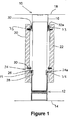
- Figure 1 is a vertical section of a partition wall system according to a first embodiment of the invention;
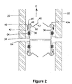
- Figure 2 is a plan view of a portion of the partition wall system shown in Figure 1;
- Figures 3A and 3B are side and end elevations of one example of the securing means used with the first embodiment;
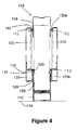
- Figure 4 is a vertical section of a partition wall system according to a second embodiment of this invention;
- Figure 5 is a plan view of the partition wall system shown in Figure 4;
- Figure 6 is a vertical section of a partition according to a third embodiment of the invention; and
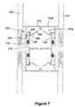
- Figure 7 is a plan view of a portion of the partition wall system shown in Figure 6.
-
- In Figure 1 there is shown a vertical section of a partition wall system according to a first embodiment. The partition wall system (10) is formed by a frame having a pair of upright supports (34) secured to the ceiling and floor, a lower support (12) and, preferably, upper support (16) positioned intermediate the first and second upright supports (34). The lower support (12) is secured to the floor and the upper support (16) is secured to the ceiling, by screws or other suitable fixing means known in the art.
- A first wall panel (20) is fitted along one side of the lower and upper supports (12, 16) shown in Figure 1. Likewise, on the opposing side of the lower and upper supports (12, 16) a second wall panel (22) is secured to the frame. In this embodiment the lower portions of the wall panels (20, 22) are secured to the frame by locating means (24). The locating means (24), in this embodiment, comprises a hook (26) (or longitudinal seating) which is shaped to locate and engage an upstanding part (28) of the lower support (14). The upstanding part (28) may be provided by a wall of the lower support. In Figure 1, the lower support (14) comprises a section which is substantially 'U' shaped to define opposed upstanding parts (28, 28A).
- The hook (26) is secured to the partition panel (20) by a screw (30) or other known suitable fixing means. The hook (26) is adapted to locate the wall in the desired position and to engage and disengage with the upstanding wall (28), thereby to allow the partition to be de-mountable.
- The second partition panel (22) is provided with identical locating means (24A) and so shall not be described in any great detail.
- In use, the partition panel (20, 22) is engaged with the lower support (12) so that the weight of the partition wall is transmitted directly through the lower support to the floor, thereby providing a more rigid structure than the prior art partitioning systems, outlined above.
- In Figure 1, the partitions panels (20, 22) are also provided with spacers (32, 32A) positioned adjacent an upper edge of the partition panels to space the partition walls from the upper support (16) thereby to ensure the partition walls are upright.
- Preferably, a seal (33, 35) is applied between the spacer (32) and the upper support (16) to seal the upper edge of the partition walls (20, 22) and, also, between the lower support (12) and partition wall (20). More preferably, the seal (35) is positioned between the upper edge of the upstanding wall (28) and the part of the hook (26) which rests on the wall (28).
- The first and second upright supports (34), one of which is shown in Figure 2 in section are, in this embodiment, substantially 'U' shaped, to provide opposed first and second wall sections (36, 38) which are used to receive and retain corresponding securing means (or clip) to hold the partition walls (20, 22) in an upright position. Of course, other profiles of upright support (34) can be used without departing from the scope of the invention.
- In Figure 2 there is illustrated one example of the securing means (40) attached to each of the partition walls (20, 22). However, it is envisaged that there will comprise a plurality of such securing means (40, 40A) positioned at spaced intervals adjacent the side edges and/or upper edge of the partition wall (20, 22). The number of securing means (40, 40A) attached to each partition wall will be determined by a number of factors, including for example, the size of the wall and its weight.
- Turning in detail to the construction of the preferred form of the securing means (40) there comprises a support plate (42) which is secured to the partition wall by a screw (44) or other suitable fixing means. Extending from the support plate (42), there is a flexural member (46) shaped to provide a recess (48) and a protruding part (50).
- In this embodiment, the member (46) is generally 'S' shaped although, such a profile is non-limiting and other shapes are envisaged. The member (46) is manufactured from spring steel, mild steel, plastics or other flexible material so that it can flex during use. Thus, the recessed portion (48) is adapted to receive the corresponding first wall section (36) of the upright support (34) and is held in place by the corresponding protruding part (50) of the member (46).
- In order to secure the securing means (40) to the upright section (34) the leading face (52) of the member (46) comes into contact with the first wall section (36) as the partition wall is position, which causes the flexural member (46) to flex inwardly (in direction X shown in Figure 2). The free edge of the first wall section (36) passes beyond the protruding section (50) and into the recessed section (48), to be retained therewith; and causes the member (46) to flex back to its original position. Thus, the securing means (40) functions as a "clip" to engage the partition panel (20) with the upright support. The support plate (42) may further comprise a recess for receiving a seal (54) for sealing the gap between the partition panel (20) and the upright section (34).
- The securing means (40A) for the second partition panel (22) is identical to securing means (40) and is therefore not described in any further detail.
- In Figure 2, it will be seen that the upright section (34) can be secured to an adjacent upright (84) prior to fitting the partition wall to form a rigid 'H' shaped structure thereby improving the rigidity of the frame.
- Figures 3A and 3B illustrate the securing means (40) in more detail in which is shown a support plate (42), apertures (44) for receiving a screw and the flexural member (46). Figure 3B illustrates a preferred profile of the flexural member (46).
- Turning to Figures 4 and 5 there is shown a second embodiment of partition wall structure. The second embodiment is similar to the first embodiment with like parts designated by the same reference numerals with the prefix "1". Only the differences between the first and second embodiments will be described in any greater detail.
- The partition wall is formed from a steel panel which is backed by plasterboard for fire and acoustic properties, and is provided with a box section (123, 123A) along the base portion of the partition wall (120, 122). The box sections (123, 123A) provide additional strength along the lower part of the wall. The hook (126) is provided by a sheet that is secured to the partition wall and to the upper wall (125) of the box section. Preferably, the protruding wall (128) of the base support further comprises a second wall (129), or folded extension of the protruding wall, to provide additional support for the base structure.
- In Figure 5 the securing means (140) is similar to the securing means (40) in the first embodiment. However, the fixing plate is replaced with a box section (155) secured or welded to the front face of the partition wall (120). The box section (155) provides additional lateral strength along the opposed side edges of the partition wall. A seal (157) is secured to the box section to seal the gap between the upright support (134) and box section (155). In all other respects the partition wall is constructed and fixed in like manner to the first embodiment.
- Turning to Figures 6 and 7, there is shown a third embodiment of partition wall structure. The third embodiment is similar to the first embodiment with like parts designated by the same reference numerals with the prefix "2". Only the differences between the first and third embodiments will be described in any greater detail.
- The third embodiment comprises double glazed panels (220, 222). As the panels are liable to flex then additional support structures are provided adjacent the upper and lower supports (212, 216). Thus, in this embodiment, the locating means (224) is provided by a support member (225) secured to the glazed panel (220) by an adhesive for example, structural silicone or other means (223). The support is shaped to define an outer wall (227) and an inner wall (229) adapted to engage either side of the upstanding portion (228) of the lower section. The support further comprises a spacer element (231) which protrudes inwardly and is adapted to abut a corresponding spacer (233A) attached to glazed panel (222).
- Similarly, an upper spacer (227) is secured to an upper portion of the glazed panel (220) by adhesive or other suitable means (235). This spacer is further secured to the upper support (216) by the provision of an extension (239) which is secured to the upper section by adhesive or other suitable means (237). A central spacer (241) is provided and is positioned in abutment with corresponding spacer (241 A) of the glazed panel (222), as shown in Figure 6.
- In Figure 7 the securing means is broadly similar to the first embodiment. However, the securing plate (242) is adapted to further incorporate a spacer (243) which is adapted to overlie the upstanding section (234) and to be in abutment with corresponding spacer section (243A) for the corresponding glazed panel (222).
- A further benefit of the spacers (243, 243A, 231, 241) is that it provides a more attractive inner section and covers up the frame.
- The aforementioned embodiments are constructed "off-site" thereby improving the speed, fitting and accuracy of the units. Furthermore, each unit uses common parts to enable different parts to be interchangeable and to be designed for "fast track" site installation.
- The solid panels will usually be 15mm steel or plasterboard composite, MDF and laminate or a single or double glazed flush fit system. In those embodiments with the steel or plasterboard constructions they may further comprise sound barrier mats and/or additional insulation between the opposed walls. It is envisaged that the various elements of the present invention and the preferred embodiments can be interchanged to provide modular sections to be applied to new units or supplied on a retro fit basis.
Claims (15)
- A partition wall structure for dividing internal areas of a building having a frame secured to the floor and ceiling of the building, the frame comprising first and second upright sections spaced apart by a lower support, the wall structure further comprising a wall panel located on the lower support by locating means, whereby the weight of the partition wall is transmitted via the locating means to the lower support, wherein the upper portion of the wall panel is retained in an upright position by securing means secured to the wall panel and adapted to be engaged with a protruding wall section of the upright support thereby to allow the partition panel to be detachably connected with respect to the frame.
- A partition wall structure as claimed in Claim 1, wherein the locating means comprises a hook protruding from a lower portion of the wall panel adapted to engage an upstanding portion of the lower support.
- A partition wall structure as claimed in Claim 2, wherein the lower section is substantially 'U' shaped to define opposed upstanding portions.
- A partition wall structure as claimed in any of Claims 1 to 3, wherein the securing means comprises an member secured to the partition wall and adapted to flex, wherein the member engages and retains the protruding wall section in a detachable manner.
- A partition wall structure as claimed in Claim 4, wherein the upright support is substantially 'U' shaped to define opposed protruding wall sections.
- A partition wall structure as claimed in any of Claims 4 or 5. wherein there comprises a plurality of securing means secured to the side portions of the partition wall at spaced positions.
- A partition wall structure as claimed in any preceding claim, wherein the partition wall is manufactured from any one of steel, MDF, plasterboard or glass.
- A partition wall structure as claimed in any preceding claim wherein the frame further comprises an upper support located intermediate the first and second upright sections.
- A partition wall structure as claimed in any preceding claim wherein there comprises a second partition wall located in the lower section by locating means and secured to the upright by securing means.
- A partition wall structure as claimed in Claim 9 wherein there further comprises a spacer secured to the first partition wall and adapted to space the first partition wall from the second partition wall.
- A securing means for securing a partition wall to an upright section of a frame secured to a building, the upright having a protruding portion, which securing means comprises a support plate adapted to be fitted to the partition wall and an elongate flexural member having a recess, which member is adapted to flex on contact with the protruding portion to cause the protruding portion to be received and held in the recess, to detachably connect the partition wall to the upright section.
- Securing means as claimed in Claim 8, wherein the upright section is substantially 'U' shaped to define opposed protruding wall sections.
- A partition wall structure substantially or hereinbefore described by reference to or as illustrated in Figures 1 and 2, 4 and 5 or 6 and 7.
- A partition wall structure substantially as hereinbefore described.
- A securing means substantially as hereinbefore described by reference to or illustrated in Figures 2 and 3A and 3B.
Applications Claiming Priority (2)
| Application Number | Priority Date | Filing Date | Title |
|---|---|---|---|
| GB0407471 | 2004-04-01 | ||
| GB0407471A GB0407471D0 (en) | 2004-04-01 | 2004-04-01 | Partition wall structure |
Publications (2)
| Publication Number | Publication Date |
|---|---|
| EP1582642A2 true EP1582642A2 (en) | 2005-10-05 |
| EP1582642A3 EP1582642A3 (en) | 2007-12-19 |
Family
ID=32247719
Family Applications (1)
| Application Number | Title | Priority Date | Filing Date |
|---|---|---|---|
| EP05252005A Withdrawn EP1582642A3 (en) | 2004-04-01 | 2005-03-30 | Partition wall structure |
Country Status (2)
| Country | Link |
|---|---|
| EP (1) | EP1582642A3 (en) |
| GB (1) | GB0407471D0 (en) |
Cited By (3)
| Publication number | Priority date | Publication date | Assignee | Title |
|---|---|---|---|---|
| TWI416001B (en) * | 2007-09-21 | 2013-11-21 | Formosa Stone Panels Inc | An architectural decoration composing module and using the architectural module to modify the architecture wall or floor |
| RU180770U1 (en) * | 2018-02-15 | 2018-06-22 | Александр Александрович Ефимов | Partition mount |
| CN109487924A (en) * | 2018-09-10 | 2019-03-19 | 中建三局集团有限公司 | The constructing structure and method of hanging lightweight bulkhead under a kind of steel-frame structure is fixed |
Families Citing this family (1)
| Publication number | Priority date | Publication date | Assignee | Title |
|---|---|---|---|---|
| CN111005479A (en) * | 2019-12-06 | 2020-04-14 | 上海模卡建筑工程科技发展有限公司 | Prefabricated wall body of assembled |
Citations (4)
| Publication number | Priority date | Publication date | Assignee | Title |
|---|---|---|---|---|
| US2958982A (en) * | 1953-08-17 | 1960-11-08 | United States Gypsum Co | Building construction |
| US3232018A (en) * | 1962-11-13 | 1966-02-01 | Dominion Bridge Co Ltd | Resilient clip securing panels in spaced relation to wall studs |
| EP1094167A2 (en) * | 1999-10-22 | 2001-04-25 | Faram S.p.A. | Partition wall structure with quick assembly of filler panels |
| EP1302601A1 (en) * | 2001-10-12 | 2003-04-16 | Technal | Device for interior partition wall system with hollow joint |
-
2004
- 2004-04-01 GB GB0407471A patent/GB0407471D0/en not_active Ceased
-
2005
- 2005-03-30 EP EP05252005A patent/EP1582642A3/en not_active Withdrawn
Patent Citations (4)
| Publication number | Priority date | Publication date | Assignee | Title |
|---|---|---|---|---|
| US2958982A (en) * | 1953-08-17 | 1960-11-08 | United States Gypsum Co | Building construction |
| US3232018A (en) * | 1962-11-13 | 1966-02-01 | Dominion Bridge Co Ltd | Resilient clip securing panels in spaced relation to wall studs |
| EP1094167A2 (en) * | 1999-10-22 | 2001-04-25 | Faram S.p.A. | Partition wall structure with quick assembly of filler panels |
| EP1302601A1 (en) * | 2001-10-12 | 2003-04-16 | Technal | Device for interior partition wall system with hollow joint |
Cited By (3)
| Publication number | Priority date | Publication date | Assignee | Title |
|---|---|---|---|---|
| TWI416001B (en) * | 2007-09-21 | 2013-11-21 | Formosa Stone Panels Inc | An architectural decoration composing module and using the architectural module to modify the architecture wall or floor |
| RU180770U1 (en) * | 2018-02-15 | 2018-06-22 | Александр Александрович Ефимов | Partition mount |
| CN109487924A (en) * | 2018-09-10 | 2019-03-19 | 中建三局集团有限公司 | The constructing structure and method of hanging lightweight bulkhead under a kind of steel-frame structure is fixed |
Also Published As
| Publication number | Publication date |
|---|---|
| GB0407471D0 (en) | 2004-05-05 |
| EP1582642A3 (en) | 2007-12-19 |
Similar Documents
| Publication | Publication Date | Title |
|---|---|---|
| US5822935A (en) | Solid-core wall system | |
| US3537217A (en) | Wall structures | |
| US9359771B1 (en) | Removable highly secured wall panel mounting system | |
| US2958403A (en) | Demountable partition | |
| EP2929103B1 (en) | Ceiling system | |
| CA2900242C (en) | Partition wall system including clamping of the panels | |
| US20040049999A1 (en) | Curved wall panel system | |
| US7810294B2 (en) | Housing construction system | |
| US3925948A (en) | Modular wall construction | |
| WO1999046453B1 (en) | Variable width end panel | |
| RU2719865C2 (en) | Ceiling installation system and corresponding method | |
| US20140157707A1 (en) | Free-standing wall | |
| EP1582642A2 (en) | Partition wall structure | |
| EP1094167A2 (en) | Partition wall structure with quick assembly of filler panels | |
| US2054189A (en) | Building construction | |
| GB2600285A (en) | Prefabricated frames for masonry slips | |
| US4080766A (en) | Demountable partition structure | |
| US4640076A (en) | Assembly system with clip for installing marble panels | |
| US20060272277A1 (en) | Systems and methods for installing panels | |
| US9119469B2 (en) | Platform assembly for supporting cabinets | |
| CN109098401B (en) | Decoration assembly | |
| US2047572A (en) | Thick paneled metallic wall structure | |
| US20230358036A1 (en) | System and method for mounting a panel to an internal frame of a modular wall | |
| CA3108473C (en) | Cabinets, cabinet assembly systems and methods of cabinet construction | |
| US7918052B2 (en) | Drywall construction for supporting an installation element and method for fastening the installation element |
Legal Events
| Date | Code | Title | Description |
|---|---|---|---|
| PUAI | Public reference made under article 153(3) epc to a published international application that has entered the european phase |
Free format text: ORIGINAL CODE: 0009012 |
|
| AK | Designated contracting states |
Kind code of ref document: A2 Designated state(s): AT BE BG CH CY CZ DE DK EE ES FI FR GB GR HU IE IS IT LI LT LU MC NL PL PT RO SE SI SK TR |
|
| AX | Request for extension of the european patent |
Extension state: AL BA HR LV MK YU |
|
| RIC1 | Information provided on ipc code assigned before grant |
Ipc: E04B 2/74 20060101ALI20070913BHEP Ipc: E04B 2/78 20060101AFI20050627BHEP |
|
| PUAL | Search report despatched |
Free format text: ORIGINAL CODE: 0009013 |
|
| AK | Designated contracting states |
Kind code of ref document: A3 Designated state(s): AT BE BG CH CY CZ DE DK EE ES FI FR GB GR HU IE IS IT LI LT LU MC NL PL PT RO SE SI SK TR |
|
| AX | Request for extension of the european patent |
Extension state: AL BA HR LV MK YU |
|
| STAA | Information on the status of an ep patent application or granted ep patent |
Free format text: STATUS: THE APPLICATION IS DEEMED TO BE WITHDRAWN |
|
| 18D | Application deemed to be withdrawn |
Effective date: 20071002 |