EP1582448A2 - Bicycle crank arm - Google Patents
Bicycle crank arm Download PDFInfo
- Publication number
- EP1582448A2 EP1582448A2 EP05007090A EP05007090A EP1582448A2 EP 1582448 A2 EP1582448 A2 EP 1582448A2 EP 05007090 A EP05007090 A EP 05007090A EP 05007090 A EP05007090 A EP 05007090A EP 1582448 A2 EP1582448 A2 EP 1582448A2
- Authority
- EP
- European Patent Office
- Prior art keywords
- crank
- end portion
- mounting end
- pedal
- attachment part
- Prior art date
- Legal status (The legal status is an assumption and is not a legal conclusion. Google has not performed a legal analysis and makes no representation as to the accuracy of the status listed.)
- Withdrawn
Links
- 238000000034 method Methods 0.000 claims abstract description 25
- 239000000463 material Substances 0.000 claims description 45
- 238000005304 joining Methods 0.000 claims description 2
- 239000000945 filler Substances 0.000 claims 2
- 230000002093 peripheral effect Effects 0.000 claims 2
- 238000007493 shaping process Methods 0.000 claims 1
- 238000005242 forging Methods 0.000 description 7
- 238000004519 manufacturing process Methods 0.000 description 7
- 239000000047 product Substances 0.000 description 6
- 238000007796 conventional method Methods 0.000 description 5
- 238000003825 pressing Methods 0.000 description 5
- 230000037237 body shape Effects 0.000 description 4
- 239000007787 solid Substances 0.000 description 4
- 229910000838 Al alloy Inorganic materials 0.000 description 3
- 229910001040 Beta-titanium Inorganic materials 0.000 description 3
- 229910045601 alloy Inorganic materials 0.000 description 3
- 239000000956 alloy Substances 0.000 description 3
- 238000005520 cutting process Methods 0.000 description 3
- 238000013461 design Methods 0.000 description 3
- 238000010438 heat treatment Methods 0.000 description 3
- 230000008569 process Effects 0.000 description 3
- 238000012545 processing Methods 0.000 description 3
- 230000003068 static effect Effects 0.000 description 3
- XLYOFNOQVPJJNP-UHFFFAOYSA-N water Substances O XLYOFNOQVPJJNP-UHFFFAOYSA-N 0.000 description 3
- 238000003466 welding Methods 0.000 description 3
- 229910000831 Steel Inorganic materials 0.000 description 2
- 230000032683 aging Effects 0.000 description 2
- 230000000670 limiting effect Effects 0.000 description 2
- 238000003754 machining Methods 0.000 description 2
- 230000004048 modification Effects 0.000 description 2
- 238000012986 modification Methods 0.000 description 2
- 230000009467 reduction Effects 0.000 description 2
- 239000010959 steel Substances 0.000 description 2
- 238000012546 transfer Methods 0.000 description 2
- 230000007704 transition Effects 0.000 description 2
- 229910000975 Carbon steel Inorganic materials 0.000 description 1
- RTAQQCXQSZGOHL-UHFFFAOYSA-N Titanium Chemical compound [Ti] RTAQQCXQSZGOHL-UHFFFAOYSA-N 0.000 description 1
- 239000010962 carbon steel Substances 0.000 description 1
- 230000008859 change Effects 0.000 description 1
- 238000010273 cold forging Methods 0.000 description 1
- 230000002860 competitive effect Effects 0.000 description 1
- 230000003247 decreasing effect Effects 0.000 description 1
- 238000006073 displacement reaction Methods 0.000 description 1
- 230000009977 dual effect Effects 0.000 description 1
- 230000000694 effects Effects 0.000 description 1
- 238000005516 engineering process Methods 0.000 description 1
- 239000012467 final product Substances 0.000 description 1
- 239000006260 foam Substances 0.000 description 1
- 230000005484 gravity Effects 0.000 description 1
- 239000011796 hollow space material Substances 0.000 description 1
- 230000006872 improvement Effects 0.000 description 1
- 238000012805 post-processing Methods 0.000 description 1
- 238000003672 processing method Methods 0.000 description 1
- 238000004080 punching Methods 0.000 description 1
- 238000010791 quenching Methods 0.000 description 1
- 230000000171 quenching effect Effects 0.000 description 1
- 239000002994 raw material Substances 0.000 description 1
- 230000002829 reductive effect Effects 0.000 description 1
- 239000011347 resin Substances 0.000 description 1
- 229920005989 resin Polymers 0.000 description 1
- 238000005482 strain hardening Methods 0.000 description 1
- 229910052719 titanium Inorganic materials 0.000 description 1
- 239000010936 titanium Substances 0.000 description 1
Images



Classifications
-
- B—PERFORMING OPERATIONS; TRANSPORTING
- B62—LAND VEHICLES FOR TRAVELLING OTHERWISE THAN ON RAILS
- B62M—RIDER PROPULSION OF WHEELED VEHICLES OR SLEDGES; POWERED PROPULSION OF SLEDGES OR SINGLE-TRACK CYCLES; TRANSMISSIONS SPECIALLY ADAPTED FOR SUCH VEHICLES
- B62M3/00—Construction of cranks operated by hand or foot
-
- B—PERFORMING OPERATIONS; TRANSPORTING
- B21—MECHANICAL METAL-WORKING WITHOUT ESSENTIALLY REMOVING MATERIAL; PUNCHING METAL
- B21D—WORKING OR PROCESSING OF SHEET METAL OR METAL TUBES, RODS OR PROFILES WITHOUT ESSENTIALLY REMOVING MATERIAL; PUNCHING METAL
- B21D53/00—Making other particular articles
- B21D53/86—Making other particular articles other parts for bicycles or motorcycles
-
- Y—GENERAL TAGGING OF NEW TECHNOLOGICAL DEVELOPMENTS; GENERAL TAGGING OF CROSS-SECTIONAL TECHNOLOGIES SPANNING OVER SEVERAL SECTIONS OF THE IPC; TECHNICAL SUBJECTS COVERED BY FORMER USPC CROSS-REFERENCE ART COLLECTIONS [XRACs] AND DIGESTS
- Y10—TECHNICAL SUBJECTS COVERED BY FORMER USPC
- Y10T—TECHNICAL SUBJECTS COVERED BY FORMER US CLASSIFICATION
- Y10T74/00—Machine element or mechanism
- Y10T74/21—Elements
- Y10T74/2164—Cranks and pedals
Definitions
- the present invention generally relates to a bicycle crank and a method of producing a bicycle crank. More specifically, the present invention relates to a bicycle crank arm produced by hydroforming.
- Bicycling is becoming an increasingly more popular form of recreation as well as a means of transportation. Moreover, bicycling has also become a very popular competitive sport. Whether the bicycle is used for recreation, transportation or competition, the current trend is to construct bicycles which are stronger as well as lighter than prior bicycles. In other words, in pursuit of faster running speed, it is desirable to reduce the weight for all kinds of parts of the bicycle.
- the bicycle crank is one of the most important parts of a bicycle since it transfers the leg power of a rider to rotational movement.
- weight savings important; but also maintaining the rigidity of the bicycle crank is important to efficiently transfer leg power are required.
- Each bicycle has a pair of bicycle crank arms which are coupled to the bicycle crank spindle or axle.
- the crank arms extend outwardly from the crank spindle in opposite directions and have pedals attached to their free ends for supporting the rider's feet. Rotation of the pedals by the rider causes one or more front sprockets to rotate which in turn moves the bicycle chain to rotate one or more rear sprockets, and thus, rotate the rear wheel of the bicycle.
- the front sprocket or sprockets are coupled directly to the crank arm by fastening fingers.
- the fastening fingers are coupled to the hub portion of the crank arm, and extend radially outwardly from the hub portion of the crank arm.
- these bicycle crank arms are produced with hollow crank bodies to realize weight saving.
- These bicycle crank arms are also often produced from forged aluminum alloy to be lightweight.
- One conventional method of producing a conventional hollow crank body will now be briefly described.
- the first step in producing a conventional hollow crank body involves first creating a solid cylindrical member. This solid cylindrical member is often produced by cutting a steel bar. Next, as the second step, a blind bore is formed in a first end of the solid cylindrical member to produce a cup-shaped unprocessed tube with one open end and one closed end. Next, in the third step, the solid cylindrical member is processed to form a crank shaped body by performing multiple forging processes. In this step, the open end of the blind bore is also pressure-bonded by forging to close the end of the crank shaped body.
- the crank shaped body is further processed by further forging to form nearly the final crank shape.
- the final crank shape is cut by machining to form the final crank product which includes a threaded hole on the pedal end and a spline groove hole on the gear end.
- the surface of the crank arm is ground and/or polished to become ready for use.
- a conventional production method for crank arms is to make a hollow crank body for weight saving, requires many steps, and they are reflected in the production cost.
- the thickness of the hollow part is limited to be approximately 4 mm even at the thinnest point. Since all parts of the crank arm are made as thin as possible with this conventional forging technique, additional weight saving is difficult to obtain using this conventional forging technique. Materials are also limited to aluminum alloy because it is needed to form a complex shape by forging a hollow space.
- One object of the present invention is to provide a bicycle crank which is lightweight, strong and highly rigid.
- Another object of the present invention is to provide a bicycle crank which has a highly complex shape that can be easily produced.
- Another object of the present invention is to provide a sprocket supporting crank arm which is relatively easy and inexpensive to manufacture.
- the foregoing objects can basically be attained by providing a bicycle crank arm formed by tube hydroforming.
- the bicycle crank arm basically comprises a central crank body portion, crank axle mounting end portion and a pedal mounting end portion.
- the crank axle mounting end portion is disposed at a first end of the central crank body.
- the pedal mounting end portion is disposed at a second end of the central crank body.
- the central crank body portion is formed together with the crank axle mounting end portion and the pedal mounting end portion by tube hydroforming as a hollow one-piece, unitary member with an interior space.
- crank arm of this invention also for material quality, highly rigid and strong materials can be applied, and by forming together a crank made of tubing material, for which it is easy to select thickness, by being entirely thinned by the hydroforming method, and by keeping open an edge part that does not require strength after being formed by the hydroforming method, or by being covered by a light component such as plastic, weight saving and increase of strength and rigidity can be achieved.
- crank body can be provided as a hollow part with a very advanced design.
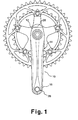
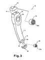
- the hollow bicycle crank arm 10 includes a first crank axle mounting end portion 12, a central crank body portion 14 and a second pedal mounting end portion 16.
- the hollow bicycle crank arm 10 is preferably a one-piece, unitary member that is produced by the tube hydroforming method described below.
- the hollow bicycle crank arm 10 can be highly designed in a complex shape, while still being light, highly strong and highly rigid.
- the hollow bicycle crank arm 10 can be produced using the tube hydroforming method described below, such that its circumferential lengths at selected cross sections of this hollow bicycle crank arm 10 is 79.8 mm at minimum and 113 mm at maximum, and its a longitudinal length is 200 mm measured between the end edges.
- the crank axle mounting end portion 12 has an open end 22 and a crank axle hole 24.
- the open end 22 of the crank axle mounting end portion 12 is dimensioned to receive a crank axle attachment part 26 that is located within the crank axle mounting end portion 12 beneath the crank axle hole 24.
- the crank axle attachment part 26 is an annular member with a plurality of internal splines 26a formed along its internal surface.
- the splines 26a are configured and arranged to engage a plurality of external splines of a crank axle (not shown).
- the outer diameter or width of the crank axle attachment part 26 is larger than the diameter or width of the crank axle hole 24 of the crank axle mounting end portion 12. In other words, an annular overlap is formed by the crank axle mounting end portion 12 with the outer periphery of the crank axle attachment part 26.
- crank axle hole 24 of the crank axle mounting end portion 12 has a predetermined diameter or width that is dimensioned to receive a crank axle therethrough, but prevent the crank axle attachment part 26 from falling therethrough.
- the open end 22 is preferably covered by an end cap 28, which closed the end of the crank axle mounting end portion 12.
- the end cap 28 is step shaped so that a smooth transition is formed between the exterior surfaces of the crank axle mounting end portion 12 and the exterior surfaces of the end cap 28.
- a continuously smooth, flush exterior surface extends over each of the interfaces between the contiguous exterior surfaces of the crank axle mounting end portion 12 and the end cap 28.
- the pedal mounting end portion 16 has an open end 32 and a pedal spindle hole 34.
- the open end 32 of the pedal mounting end portion 16 is dimensioned to receive a pedal spindle attachment part 36 that is located within the pedal mounting end portion 16 beneath the pedal spindle hole 34.
- the pedal spindle attachment part 36 is an annular member with a set of internal threads 36a formed along its internal surface. The threads 36a are configured and arranged to engage external threads of a pedal spindle (not shown).
- the outer diameter or width of the pedal spindle attachment part 36 is larger than the diameter or width of the pedal spindle hole 34 of the pedal mounting end portion 16. In other words, an annular overlap is formed by the pedal mounting end portion 16 with the outer periphery of the pedal spindle attachment part 36.
- the pedal spindle hole 34 of the pedal mounting end portion 16 has a predetermined diameter or width that is dimensioned to receive a pedal spindle therethrough, but prevent the pedal spindle attachment part 36 from falling therethrough.
- the open end 32 is preferably covered by an end cap 38, which closed the end of the pedal mounting end portion 16.
- the end cap 28 is configured such that a smooth transition is formed between the exterior surface of the pedal mounting end portion 16 and the exterior surface of the end cap 38.
- a continuously smooth, flush exterior surface extends over each of the interfaces between the contiguous exterior surfaces of the pedal mounting end portion 16 and the end cap 38.
- Figures 4-10 will be used to explain a production method of manufacturing the hollow bicycle crank arm 10 by using tube hydroforming in accordance with this invention.
- tube hydroforming is a method wherein a tube or hollow crank material (Figure 4) is used as a base material for the hollow bicycle crank arm 10, and then tube hydroforming is performed on the tube material to form a crank body ( Figure 7).
- this base material or hollow crank material is set into a mold that has a predetermined shape for forming the crank body illustrated in Figure 7.
- water is forced into the tube of hollow crank material, with an increasing axis force being applied to the tube ends, as needed, and increasing the water pressure in the tube such that the hollow crank material is deformed to the shape of the mold.
- the crank body is cut to its final shape ( Figure 7) and the attachment parts 26 and 36 and the end caps 28 and 38 are installed ( Figures 8 and 9).
- tube hydroforming method itself is already well known as a processing method.
- the basic technology of tube hydroforming can be utilized without modification to produce the hollow bicycle crank arm 10 of the present invention as explained below.
- tube hydroforming is a well-known method, it defies the common wisdom that a crank body, which is conventionally an integral structure with both ends closed, can be produced by tube hydroforming.
- tube hydroforming is typically performed on a tube that is open at both ends.
- a tube material 40 is prepared as a tubular base material for the bicycle crank arm 10.
- the production method of forming the tubular base material is not critical to the present invention.
- the tubular base material can be a welded tube or a seamless tube.
- a low specific gravity material is preferably for weight saving, while a material with a high Young's modulus is preferably to increase rigidity.
- the tubular base material has a high yield point and tensile strength to increase strength.
- the tubular base material is soft when processing and hard when finished.
- the first type of material is one that has a large n value, that is easily work-hardened, and that increases strength of the product by leveraging work-hardening when tube hydroforming.
- One example of the first type of material is SUS304 that is work-hardened.
- the second type of material is one that has comparatively low material strength and that is easy to process, and then the material strength of product is increased by heat treatment after forming steps by, for example, aging heat treatment.
- Examples of the second type of material are beta titanium alloys that are heat treated or carbon steel that is hardened with quenching, etc.
- an initial forming step may need to be conducted prior to the tube hydroforming process as seen in Figure 5.
- the bicycle crank arm 10 cannot be formed.
- the ratio to expand the tube will be too large when using a tube with an initial diameter or width that is equal to the smallest circumferential length of the crank body, then the ratio to expand the tube may be too large.
- the tube material 40 that corresponds with the maximum value of circumferential length of cross section is prepared as shown in Figure 4.
- a preliminary forming step is conducted to form an initially deformed tube 42 in which the diameter of the unprocessed tube or tube material 40 ( Figure 4) is at least partially changed by swagging and/or die squeezing.
- the initially deformed tube 42 preferably has been deformed so that the circumferential lengths are various points substantially correspond to the circumferential length of the final crank body shape.
- the circumferential length of the initially deformed tube 42 varies along its length (longitudinal direction) to substantially correspond to the circumferential length of the final crank body shape. In this way, the amount change in the cross sectional length of the initially deformed tube 42 to the final crank body shape can be minimized as needed and/or desired.
- the tube hydroforming method is implemented to form the general shape of the crank body as shown in Figure 7.
- forming is implemented by pressing the initially deformed tube 42 into fit a hydroforming mold. This pressing changes the shape of the initially deformed tube 42 ( Figure 5) to the shape of a preformed pressed tube 44 as seen in Figure 6.
- the preformed pressed tube 44 which is set in the hydroforming mold, has pressurized water injected inside, with an increasing axis force being applied as needed and the inside pressure increasing to cause the preformed pressed tube 44 to conform to the shape of the mold.
- a detailed description of the hydroforming mold, the hydroforming equipment, and etc. have been omitted.
- crank axle hole 24 and the pedal spindle hole 34 are formed and excess material at the ends are removed from the intermediate crank body shape as shown in Figure 7. Creating holes at this time can be implemented by machining or punching as needed and/or desired.
- the crank axle attachment part 26 and the pedal spindle attachment part 36 are inserted into the open ends 22 and 32, respectively, of the crank body.
- the crank axle attachment part 26 and the pedal spindle attachment part 36 are then welded or otherwise fixedly secured to the crank body.
- the joining method is not particularly limited to welding or bonding, etc. but to prevent HAZ softening of welding parts, a laser weld is one preferred method.
- crank axle attachment part 26 and the pedal spindle attachment part 36 can not be inserted into the crank body from the holes 24 and 34, because the widths of the attachment parts 26 and 36 are larger than the diameters of the holes 24 and 34.
- This arrangement is desirable for the attachment parts 26 and 36 because if the attachment parts 26 and 36 were mounted by inserting into the holes 24 and 34 of the hydroformed crank body, then the attachment parts 26 and 36 may separate from the crank body in the event that the joint breaks. If the joint connecting the crank axle attachment part 26 to the crank body is broken in the present invention, the crank arm 10 remains attached to the crank axle because the crank axle attachment part 26 can not fall through the hole 24.
- the end caps 28 and 38 are fixedly secured within the open ends 22 and 32, respectively to form a finished product. Since the end caps 28 and 38 are not subjected to much force or weight from the rider, the end caps 28 and 38 can be made of a light plastic. It is easily understood that it is thin and hollow so that it can make a strong appeal as a light part and be highly designed.
- a light filling material 54 can be used to fill the cavity of the crank arm 10. If proceeding to thin using high strength materials, lowering of rigidity occurs and can be a problem. In that case, by filling with the filling material 54 that consists of light resin foam, etc. in the hollow inside, a reduction in rigidity can be prevented.
- an SUS304 welded tube having a diameter of 27.1 mm and a wall thickness of 1.5 mm as the thickness was prepared as an unprocessed material. Then, both the tube ends of the unprocessed tube were die-squeezed to a diameter of 25.4 mm, and a circumferential length of 79.8 mm. Next, the tube was presses into a hydroforming mold by perform-pressing and then the tube was shaped by the hydroforming method.
- crank axle attachment part and the pedal spindle attachment part were joined to the crank body by inserting them through an open ends of the crank body, and then welding them to the crank body by laser weld.
- a crank arm with openings at both tube edges was produced.
- the crank are with both open ends was not only well designed, but also created a unique atmosphere by the aperture cutting the air when riding the bicycle.
- a plastic end caps were produced and glued the crank arm to close off the opening ends of the crank arm.
- a beta titanium alloy tube having a diameter of 34.0 mm and a wall thickness of 1.5 mm as the thickness was prepared as an unprocessed material. Then, both the tube ends of the unprocessed tube were multistage die-squeezed to diameters that fit within 5% of an expanding tube ratio at each section. Then, the tube was presses into a hydroforming mold by perform-pressing and then the tube was shaped by the hydroforming method. Next, aging heat treatment was implemented so that strength and rigidity were increased. After that, just as in the first example, post-processing was implemented. The product produced had a unique titanium surface and a very advanced designed.
- Table 1 shows advantages of the conventional method as described above and the method relating to the present invention.
- Item Conventional Method Present Invention Example 1
- Example 2 Raw Material Aluminum Alloy SUS304 Beta Titanium Alloy Product Weight 200g 200g 180g Yield 60% 90% 90% Number of Processing Steps 15 5 6 Rigidity 1 1.2 1.1 Static Strength 1 1.5 1.2 Fatigue Strength 1 1.3 1.3
- rigidity, static strength and fatigue strength are ratios for which a crank arm in the conventional method is supposed to have a value of 1.
- the rigidity was evaluated by displacement when applying the fixed load, the strength was evaluated by load which plastic deformation, and the fatigue strength was evaluated by load which was not broken after repeatedly loading more than 10 7 times.
- the entire part can be thin and hollow even in the final product.
- the shape of the crank arm is such that the large part of the circumferential length of cross section is positioned elsewhere in the tube ends, the tube ends are comparatively thin, which is ideal for forming by the hydroforming method.
Landscapes
- Engineering & Computer Science (AREA)
- Mechanical Engineering (AREA)
- Chemical & Material Sciences (AREA)
- Combustion & Propulsion (AREA)
- Transportation (AREA)
- Shafts, Cranks, Connecting Bars, And Related Bearings (AREA)
- Motorcycle And Bicycle Frame (AREA)
Abstract
Description
| Item | Conventional Method | Present Invention | |
| Example 1 | Example 2 | ||
| Raw Material | Aluminum Alloy | SUS304 | Beta Titanium Alloy |
| Product Weight | 200g | 200g | 180g |
| Yield | 60% | 90% | 90% |
| Number of Processing Steps | 15 | 5 | 6 |
| Rigidity | 1 | 1.2 | 1.1 |
| Static Strength | 1 | 1.5 | 1.2 |
| Fatigue Strength | 1 | 1.3 | 1.3 |
Claims (11)
- A bicycle crank arm (10) comprising:a central crank body portion (14);a crank axle mounting end portion (12) disposed at a first end of the central crank body portion (14); anda pedal mounting end portion (16) disposed at a second end of the central crank body portion (14),the central crank body portion (14) being formed together with the crank axle mounting end portion (12) and the pedal mounting end portion (16) by tube hydroforming as a hollow one-piece, unitary member with an interior space.
- The bicycle crank arm (10) according to claim 1, further comprising
a crank axle attachment part (26) disposed within the crank axle mounting end portion (12), and
a pedal spindle attachment part (36) disposed within the pedal mounting end portion (16). - The bicycle crank arm (10) according to claim 2, wherein
the crank axle mounting end portion (12) has a crank axle hole (24) with a width that is smaller than a width of the crank axle attachment part (26) such that the crank axle mounting end portion (12) overlaps a peripheral portion of the crank axle attachment part (26); and
the pedal mounting end portion (16) has a pedal spindle hole (34) with a width that is smaller than a width of the pedal spindle attachment part (36) such that the pedal mounting end portion (16) overlaps a peripheral portion of the pedal spindle attachment part (36). - The bicycle crank arm (10) according to claim 3, wherein
the crank axle mounting end portion (12) has a first open end (22) located at a first edge of the bicycle crank arm (10), with the first open end (22) being dimensioned such that the crank axle attachment part (26) passes therethrough; and
the pedal mounting end portion (16) has a second open end (32) located at a second edge of the bicycle crank arm (10), with the second open end (32) being dimensioned such that the pedal spindle attachment part (36) passes therethrough. - The bicycle crank arm (10) according to claim 4, further comprising
a first end cap (28) disposed in the first open end (22) of the crank axle mounting end portion (12) to close the first open end (22) of the crank axle mounting end portion (12); and
a second end cap (38) disposed in the second open end (32) of the pedal mounting end portion (16) to close the second open end (32) of the pedal mounting end portion (16). - The bicycle crank arm (10) according to claim 5, further comprising
a filler material disposed in the interior space such that substantially an entire area of the interior space is filled. - The bicycle crank arm (10) according to claim 2, wherein
the crank axle mounting end portion (12) has a first open end (22) located at a first edge of the bicycle crank arm (10), with the first open end (22) being dimensioned such that the crank axle attachment part (26) passes therethrough; and
the pedal mounting end portion (16) has a second open end (32) located at a second edge of the bicycle crank arm (10), with the second open end (32) being dimensioned such that the pedal spindle attachment part (36) passes therethrough. - The bicycle crank arm (10) according to claim 1, further comprising
a filler material disposed in the interior space such that substantially an entire area of the interior space is filled. - The bicycle crank arm (10) according to claim 1, wherein
the crank axle mounting end portion (12) has a first open end (22) located at a first edge of the bicycle crank arm (10); and
the pedal mounting end portion (16) has a second open end (32) located at a second edge of the bicycle crank arm (10). - The bicycle crank arm (10) according to claim 9, further comprising
a first end cap (28) disposed in the first open end (22) of the crank axle mounting end portion (12) to close the first open end (22) of the crank axle mounting end portion (12); and
a second end cap (38) disposed in the second open end (32) of the pedal mounting end portion (16) to close the second open end (32) f the pedal mounting end portion (16). - A method of producing a bicycle crank arm (10) comprising:forming a hollow tube with first and second open ends (22, 32);shaping the hollow tube into a crank body portion (14) by tube hydroforming; forming a crank axle hole (24) and a pedal spindle hole (34);inserting a crank axle attachment part (26) and a pedal spindle attachment part (36) into the first and second open ends (22, 32); andfixedly joining the crank axle attachment part (26) and the pedal spindle attachment part (36) to the crank body portion (14) with the crank axle attachment part (26) being aligned with the crank axle hole (24) and the pedal spindle attachment part (36) being aligned with the pedal spindle hole (34).
Applications Claiming Priority (2)
| Application Number | Priority Date | Filing Date | Title |
|---|---|---|---|
| JP2004105277 | 2004-03-31 | ||
| JP2004105277A JP2005289166A (en) | 2004-03-31 | 2004-03-31 | Bicycle crank and manufacturing method thereof |
Publications (2)
| Publication Number | Publication Date |
|---|---|
| EP1582448A2 true EP1582448A2 (en) | 2005-10-05 |
| EP1582448A3 EP1582448A3 (en) | 2007-05-30 |
Family
ID=34880067
Family Applications (1)
| Application Number | Title | Priority Date | Filing Date |
|---|---|---|---|
| EP05007090A Withdrawn EP1582448A3 (en) | 2004-03-31 | 2005-03-31 | Bicycle crank arm |
Country Status (5)
| Country | Link |
|---|---|
| US (1) | US20050217417A1 (en) |
| EP (1) | EP1582448A3 (en) |
| JP (1) | JP2005289166A (en) |
| CN (1) | CN1676413A (en) |
| TW (1) | TWI258445B (en) |
Cited By (1)
| Publication number | Priority date | Publication date | Assignee | Title |
|---|---|---|---|---|
| EP2230166A3 (en) * | 2009-03-16 | 2013-10-02 | Cycling Sports Group, Inc. | Unitary crank spindle assembly and method of fabrication |
Families Citing this family (24)
| Publication number | Priority date | Publication date | Assignee | Title |
|---|---|---|---|---|
| JP4819305B2 (en) * | 2003-09-04 | 2011-11-24 | 日産自動車株式会社 | Method for manufacturing reinforcing member |
| US8459077B2 (en) * | 2005-02-15 | 2013-06-11 | Nsk Ltd. | Manufacturing method for metal member with through hole |
| EP1792820B1 (en) * | 2005-12-02 | 2010-06-16 | Campagnolo S.R.L. | Crank assembly for a bicycle bottom bracket, shaft and pedal crank thereof |
| ATE524374T1 (en) * | 2006-02-20 | 2011-09-15 | Campagnolo Srl | BICYCLE BOTTOM BEARING |
| EP1829779B1 (en) * | 2006-03-03 | 2011-01-12 | CAMPAGNOLO S.r.l. | Bicycle bottom bracket assembly and adapter device for such an assembly |
| JP2007297040A (en) * | 2006-05-04 | 2007-11-15 | Campagnolo Spa | Crank arm assembly for bicycle |
| US7530291B2 (en) * | 2006-07-13 | 2009-05-12 | Chang Hui Lin | Crank device for bicycle |
| ITMI20070406U1 (en) * | 2007-12-05 | 2009-06-06 | Campagnolo Srl | ASSEMBLY OF CENTRAL MOVEMENT OF BICYCLE AND TREE FOR A SUCH ASSEMBLY |
| EP2110301B1 (en) * | 2008-04-17 | 2014-12-24 | CAMPAGNOLO S.r.l. | Assembly of bicycle components in mutual rotation and bicycle comprising such an assembly |
| JP5460742B2 (en) | 2009-02-27 | 2014-04-02 | ボーグワーナー インコーポレーテッド | Automotive timing chain system components and method |
| EP2230167A3 (en) * | 2009-03-19 | 2013-10-02 | Cycling Sports Group, Inc. | Bicycle crank shaft assembly |
| US20110247455A1 (en) * | 2010-04-13 | 2011-10-13 | Robert Densmore | Crank arm protector |
| US8616085B2 (en) * | 2010-08-18 | 2013-12-31 | Shimano Inc. | Bicycle crank assembly |
| EP2969729A4 (en) * | 2013-03-12 | 2017-01-18 | Cycling Sports Group, Inc. | Crank spindle assembly and method of fabrication |
| US10562588B2 (en) | 2015-09-01 | 2020-02-18 | The Hive Global, Inc | Bicycle cassette with locking connection |
| WO2017165226A1 (en) | 2016-03-24 | 2017-09-28 | The Hive Global, Inc. | Bicycle crank with spindle attachment structure |
| US11351815B2 (en) | 2017-08-21 | 2022-06-07 | The Hive Global, Inc. | Bicycle cassette with clamping connection |
| TWI625178B (en) * | 2017-11-15 | 2018-06-01 | 亞獵士科技股份有限公司 | Method for manufacturing crank set of bicycle pedal |
| US10625815B2 (en) * | 2017-12-08 | 2020-04-21 | Alex Global Technology, Inc. | Method for manufacturing bicycle crank |
| US11932351B2 (en) | 2020-07-17 | 2024-03-19 | The Hive Global, Inc. | Conical bicycle cassette sprocket structure |
| US12233975B2 (en) | 2021-03-26 | 2025-02-25 | The Hive Global Inc. | Telescopic bicycle seatpost with adjustable height and fixed frame insertion |
| US12030586B2 (en) | 2021-07-12 | 2024-07-09 | The Hive Global, Inc. | Seal for bicycle crank with differential chainring motion |
| CN120435394A (en) | 2022-11-14 | 2025-08-05 | 劲锋铁马股份有限公司 | Hub system, method and apparatus with adjustable dead zone |
| USD1068571S1 (en) * | 2023-02-28 | 2025-04-01 | 5th Axis Inc. | Bicycle crank arm |
Family Cites Families (28)
| Publication number | Priority date | Publication date | Assignee | Title |
|---|---|---|---|---|
| US602049A (en) * | 1898-04-12 | Bicycle crank-shaft | ||
| US737603A (en) * | 1903-02-16 | 1903-09-01 | Jacob S Fritz | Crank-arm connection. |
| US2350468A (en) * | 1941-11-04 | 1944-06-06 | Murray Ohio Mfg Co | Bicycle crank hanger assembly |
| US2305468A (en) * | 1942-10-07 | 1942-12-15 | Ferrigno Jerome | Indoor wind breaker |
| US3648542A (en) * | 1969-05-31 | 1972-03-14 | Dino Perotti | Pedal link assembly for bicycles |
| DE2359437A1 (en) * | 1973-11-09 | 1975-06-05 | Alfred Thun | BICYCLE PEDAL |
| US4171822A (en) * | 1978-01-10 | 1979-10-23 | Firma Alfred Thun & Co. Gmbh | Dual pedal crank assembly for bicycle |
| US4358967A (en) * | 1980-06-23 | 1982-11-16 | Kastan B Linn | Foot operated crank assembly |
| US4704919A (en) * | 1984-11-28 | 1987-11-10 | Durham Roger O | Two-piece crankshaft for bicycles |
| EP0270388B1 (en) * | 1986-10-31 | 1990-07-18 | Look Sté. | Pedal crank for a bicycle |
| US5010785A (en) * | 1990-06-11 | 1991-04-30 | Seattle Bike Supply | Crank arm for a bicylce |
| US5363721A (en) * | 1993-08-23 | 1994-11-15 | Hsiao Chia Yuan | Bicycle pedal crank dismounting device |
| US5493937A (en) * | 1993-08-23 | 1996-02-27 | Edwards; Craig H. | Light-weight bicycle crankshaft assembly utilizing two-piece axle integrally joined to crank arms |
| US5924336A (en) * | 1993-12-16 | 1999-07-20 | Richardson; Brian E. | Hollow bicycle crankshaft |
| DE19601125C2 (en) * | 1996-01-13 | 1999-01-28 | Thun Alfred & Co Gmbh | Pedal crank for a bike |
| JP3248676B2 (en) * | 1996-12-27 | 2002-01-21 | 株式会社シマノ | Bicycle crank and manufacturing method thereof |
| US5941135A (en) * | 1997-06-18 | 1999-08-24 | Schlanger; Raphael | Bicycle crankshaft assembly |
| US6314834B1 (en) * | 1999-01-25 | 2001-11-13 | Truvativ International Co., Ltd. | Hollow crank arm |
| EP1214636A1 (en) * | 1999-09-24 | 2002-06-19 | Lattimore & Tessmer, Inc. | Integrated lever assembly |
| DE20001037U1 (en) * | 2000-01-21 | 2000-03-30 | Leng, Chi Chih, Nan Tou | Bicycle crank arm |
| DE20001036U1 (en) * | 2000-01-21 | 2000-04-20 | Leng, Chi Chih, Nan Tou | Bicycle crank arm |
| EP1120336A3 (en) * | 2000-01-26 | 2002-08-07 | Cannondale Corporation | Integrated crank assembly and components therefor |
| US6266990B1 (en) * | 2000-09-06 | 2001-07-31 | William Blair Shook | Method for integrally manufacturing an one-piece forged hollow crank of a bicycle |
| US6508002B1 (en) * | 2000-11-22 | 2003-01-21 | Douglas Chiang | Bicycle crank arm and method of making same |
| ITTO20010621A1 (en) * | 2001-06-27 | 2002-12-27 | Campagnolo Srl | CRANK FOR BICYCLE AND PROCEDURE FOR ITS MANUFACTURE. |
| US6612033B1 (en) * | 2002-03-15 | 2003-09-02 | Cheng-Xun Jiang | Method for making hollow bicycle cranks |
| EP1350714A1 (en) * | 2002-03-19 | 2003-10-08 | Campagnolo Srl | Hollow crank arm for a bicycle, and process for manufacturing the same |
| EP1378433A1 (en) * | 2002-07-05 | 2004-01-07 | Joris Van Raemdonck | Hollow bicycle crank |
-
2004
- 2004-03-31 JP JP2004105277A patent/JP2005289166A/en not_active Withdrawn
-
2005
- 2005-02-01 TW TW094103071A patent/TWI258445B/en not_active IP Right Cessation
- 2005-03-24 US US11/087,553 patent/US20050217417A1/en not_active Abandoned
- 2005-03-31 EP EP05007090A patent/EP1582448A3/en not_active Withdrawn
- 2005-03-31 CN CN200510062977.7A patent/CN1676413A/en active Pending
Cited By (3)
| Publication number | Priority date | Publication date | Assignee | Title |
|---|---|---|---|---|
| EP2230166A3 (en) * | 2009-03-16 | 2013-10-02 | Cycling Sports Group, Inc. | Unitary crank spindle assembly and method of fabrication |
| US8770609B2 (en) | 2009-03-16 | 2014-07-08 | Cycling Sports Group, Inc. | Unitary crown fork assembly and method of fabrication |
| US9259777B2 (en) | 2009-03-16 | 2016-02-16 | Cycling Sports Group, Inc. | Unitary crank spindle assembly and method of fabrication |
Also Published As
| Publication number | Publication date |
|---|---|
| TW200538350A (en) | 2005-12-01 |
| JP2005289166A (en) | 2005-10-20 |
| TWI258445B (en) | 2006-07-21 |
| CN1676413A (en) | 2005-10-05 |
| EP1582448A3 (en) | 2007-05-30 |
| US20050217417A1 (en) | 2005-10-06 |
Similar Documents
| Publication | Publication Date | Title |
|---|---|---|
| US20050217417A1 (en) | Bicycle crank arm | |
| EP1495879B1 (en) | Bicycle hub outer and bicycle hub | |
| US7527277B2 (en) | Bicycle crank | |
| EP2230165B1 (en) | Unitary crown fork assembly and method of fabrication | |
| CN100491177C (en) | Composite steering rack | |
| JPH11500977A (en) | Steering column fixing assembly and manufacturing method thereof | |
| US7950153B2 (en) | Method of manufacturing a steering rack | |
| KR101257060B1 (en) | Input shaft of steering system for vehicles and manufacturing method thereof | |
| CN100522660C (en) | Bearing race in hub unit and method of manufacturing the same | |
| US10124389B2 (en) | Vehicle axle | |
| JPH05116670A (en) | Interlocking rod | |
| JP2000289677A (en) | Bicycle crank support structure | |
| EP2969729A1 (en) | Crank spindle assembly and method of fabrication | |
| US5724850A (en) | Rear fork for a motorcycle | |
| GB2169987A (en) | Crank axle for bicycles | |
| JP2000158927A (en) | Suspension arm device and manufacturing method thereof | |
| WO2006037167A1 (en) | Steering rack | |
| US20130192416A1 (en) | Crank spindle assembly and method of fabrication | |
| AU2005291841B2 (en) | Steering rack | |
| AU2004274037B2 (en) | Composite steering rack | |
| JP2009287594A (en) | Rolling bearing device and its manufacturing method | |
| AU2005318920A1 (en) | Composite steering rack | |
| JP2013518763A (en) | Bicycle hub and method of manufacturing the same | |
| JPH05208224A (en) | Assembly cam shaft and its manufacture |
Legal Events
| Date | Code | Title | Description |
|---|---|---|---|
| PUAI | Public reference made under article 153(3) epc to a published international application that has entered the european phase |
Free format text: ORIGINAL CODE: 0009012 |
|
| AK | Designated contracting states |
Kind code of ref document: A2 Designated state(s): AT BE BG CH CY CZ DE DK EE ES FI FR GB GR HU IE IS IT LI LT LU MC NL PL PT RO SE SI SK TR |
|
| AX | Request for extension of the european patent |
Extension state: AL BA HR LV MK YU |
|
| RAP1 | Party data changed (applicant data changed or rights of an application transferred) |
Owner name: SHIMANO INC. |
|
| PUAL | Search report despatched |
Free format text: ORIGINAL CODE: 0009013 |
|
| AK | Designated contracting states |
Kind code of ref document: A3 Designated state(s): AT BE BG CH CY CZ DE DK EE ES FI FR GB GR HU IE IS IT LI LT LU MC NL PL PT RO SE SI SK TR |
|
| AX | Request for extension of the european patent |
Extension state: AL BA HR LV MK YU |
|
| 17P | Request for examination filed |
Effective date: 20070604 |
|
| 17Q | First examination report despatched |
Effective date: 20070709 |
|
| STAA | Information on the status of an ep patent application or granted ep patent |
Free format text: STATUS: THE APPLICATION HAS BEEN WITHDRAWN |
|
| 18W | Application withdrawn |
Effective date: 20071010 |