EP1582353A2 - Liquid discharge device - Google Patents
Liquid discharge device Download PDFInfo
- Publication number
- EP1582353A2 EP1582353A2 EP05006993A EP05006993A EP1582353A2 EP 1582353 A2 EP1582353 A2 EP 1582353A2 EP 05006993 A EP05006993 A EP 05006993A EP 05006993 A EP05006993 A EP 05006993A EP 1582353 A2 EP1582353 A2 EP 1582353A2
- Authority
- EP
- European Patent Office
- Prior art keywords
- piezoelectric
- discharge device
- driving electrodes
- liquid discharge
- displacement elements
- Prior art date
- Legal status (The legal status is an assumption and is not a legal conclusion. Google has not performed a legal analysis and makes no representation as to the accuracy of the status listed.)
- Granted
Links
- 239000007788 liquid Substances 0.000 title claims abstract description 85
- 238000006073 displacement reaction Methods 0.000 claims abstract description 74
- 239000000919 ceramic Substances 0.000 claims abstract description 31
- 238000007641 inkjet printing Methods 0.000 claims description 2
- 238000007639 printing Methods 0.000 description 46
- 239000010410 layer Substances 0.000 description 25
- 239000000463 material Substances 0.000 description 17
- 238000000605 extraction Methods 0.000 description 12
- 150000001875 compounds Chemical class 0.000 description 11
- 229910052451 lead zirconate titanate Inorganic materials 0.000 description 9
- 238000004519 manufacturing process Methods 0.000 description 7
- PXHVJJICTQNCMI-UHFFFAOYSA-N nickel Substances [Ni] PXHVJJICTQNCMI-UHFFFAOYSA-N 0.000 description 6
- 239000012790 adhesive layer Substances 0.000 description 5
- 238000010304 firing Methods 0.000 description 5
- HFGPZNIAWCZYJU-UHFFFAOYSA-N lead zirconate titanate Chemical compound [O-2].[O-2].[O-2].[O-2].[O-2].[Ti+4].[Zr+4].[Pb+2] HFGPZNIAWCZYJU-UHFFFAOYSA-N 0.000 description 5
- MCMNRKCIXSYSNV-UHFFFAOYSA-N Zirconium dioxide Chemical compound O=[Zr]=O MCMNRKCIXSYSNV-UHFFFAOYSA-N 0.000 description 4
- 239000003513 alkali Substances 0.000 description 4
- 239000000203 mixture Substances 0.000 description 4
- 239000000843 powder Substances 0.000 description 4
- 239000000853 adhesive Substances 0.000 description 3
- 230000001070 adhesive effect Effects 0.000 description 3
- 229910052788 barium Inorganic materials 0.000 description 3
- 239000004020 conductor Substances 0.000 description 3
- 239000000470 constituent Substances 0.000 description 3
- 239000013078 crystal Substances 0.000 description 3
- NKZSPGSOXYXWQA-UHFFFAOYSA-N dioxido(oxo)titanium;lead(2+) Chemical compound [Pb+2].[O-][Ti]([O-])=O NKZSPGSOXYXWQA-UHFFFAOYSA-N 0.000 description 3
- 239000002003 electrode paste Substances 0.000 description 3
- 238000011156 evaluation Methods 0.000 description 3
- 229910052751 metal Inorganic materials 0.000 description 3
- 238000000034 method Methods 0.000 description 3
- 229910052759 nickel Inorganic materials 0.000 description 3
- BASFCYQUMIYNBI-UHFFFAOYSA-N platinum Chemical compound [Pt] BASFCYQUMIYNBI-UHFFFAOYSA-N 0.000 description 3
- 238000007650 screen-printing Methods 0.000 description 3
- 229920001187 thermosetting polymer Polymers 0.000 description 3
- 229910017060 Fe Cr Inorganic materials 0.000 description 2
- 229910002544 Fe-Cr Inorganic materials 0.000 description 2
- XEEYBQQBJWHFJM-UHFFFAOYSA-N Iron Chemical compound [Fe] XEEYBQQBJWHFJM-UHFFFAOYSA-N 0.000 description 2
- UPHIPHFJVNKLMR-UHFFFAOYSA-N chromium iron Chemical compound [Cr].[Fe] UPHIPHFJVNKLMR-UHFFFAOYSA-N 0.000 description 2
- 238000005260 corrosion Methods 0.000 description 2
- 230000007797 corrosion Effects 0.000 description 2
- 238000007599 discharging Methods 0.000 description 2
- 230000005611 electricity Effects 0.000 description 2
- 238000010438 heat treatment Methods 0.000 description 2
- HEPLMSKRHVKCAQ-UHFFFAOYSA-N lead nickel Chemical compound [Ni].[Pb] HEPLMSKRHVKCAQ-UHFFFAOYSA-N 0.000 description 2
- 238000004020 luminiscence type Methods 0.000 description 2
- 239000002184 metal Substances 0.000 description 2
- 150000002739 metals Chemical class 0.000 description 2
- ZBSCCQXBYNSKPV-UHFFFAOYSA-N oxolead;oxomagnesium;2,4,5-trioxa-1$l^{5},3$l^{5}-diniobabicyclo[1.1.1]pentane 1,3-dioxide Chemical compound [Mg]=O.[Pb]=O.[Pb]=O.[Pb]=O.O1[Nb]2(=O)O[Nb]1(=O)O2 ZBSCCQXBYNSKPV-UHFFFAOYSA-N 0.000 description 2
- 229910052697 platinum Inorganic materials 0.000 description 2
- 229910052712 strontium Inorganic materials 0.000 description 2
- 229910052719 titanium Inorganic materials 0.000 description 2
- 239000010936 titanium Substances 0.000 description 2
- 238000012546 transfer Methods 0.000 description 2
- 229910000906 Bronze Inorganic materials 0.000 description 1
- 229910001030 Iron–nickel alloy Inorganic materials 0.000 description 1
- ZOKXTWBITQBERF-UHFFFAOYSA-N Molybdenum Chemical compound [Mo] ZOKXTWBITQBERF-UHFFFAOYSA-N 0.000 description 1
- RTAQQCXQSZGOHL-UHFFFAOYSA-N Titanium Chemical compound [Ti] RTAQQCXQSZGOHL-UHFFFAOYSA-N 0.000 description 1
- 230000002411 adverse Effects 0.000 description 1
- 229910045601 alloy Inorganic materials 0.000 description 1
- 239000000956 alloy Substances 0.000 description 1
- 229910052787 antimony Inorganic materials 0.000 description 1
- DSAJWYNOEDNPEQ-UHFFFAOYSA-N barium atom Chemical compound [Ba] DSAJWYNOEDNPEQ-UHFFFAOYSA-N 0.000 description 1
- 230000015572 biosynthetic process Effects 0.000 description 1
- 239000010974 bronze Substances 0.000 description 1
- 229910052791 calcium Inorganic materials 0.000 description 1
- 229910010293 ceramic material Inorganic materials 0.000 description 1
- 238000005520 cutting process Methods 0.000 description 1
- 238000001035 drying Methods 0.000 description 1
- 229920006332 epoxy adhesive Polymers 0.000 description 1
- 239000003822 epoxy resin Substances 0.000 description 1
- 238000005530 etching Methods 0.000 description 1
- 229910052737 gold Inorganic materials 0.000 description 1
- 229910052742 iron Inorganic materials 0.000 description 1
- 238000010030 laminating Methods 0.000 description 1
- 238000012423 maintenance Methods 0.000 description 1
- 239000012528 membrane Substances 0.000 description 1
- 229910001092 metal group alloy Inorganic materials 0.000 description 1
- 239000007769 metal material Substances 0.000 description 1
- 229910052750 molybdenum Inorganic materials 0.000 description 1
- 239000011733 molybdenum Substances 0.000 description 1
- 229910052763 palladium Inorganic materials 0.000 description 1
- 239000002245 particle Substances 0.000 description 1
- 238000005192 partition Methods 0.000 description 1
- 239000005011 phenolic resin Substances 0.000 description 1
- 229920000647 polyepoxide Polymers 0.000 description 1
- 229920001955 polyphenylene ether Polymers 0.000 description 1
- 238000012545 processing Methods 0.000 description 1
- 239000002994 raw material Substances 0.000 description 1
- 229920005989 resin Polymers 0.000 description 1
- 239000011347 resin Substances 0.000 description 1
- 229910052703 rhodium Inorganic materials 0.000 description 1
- 238000005096 rolling process Methods 0.000 description 1
- 239000004065 semiconductor Substances 0.000 description 1
- 229910052709 silver Inorganic materials 0.000 description 1
- UYLYBEXRJGPQSH-UHFFFAOYSA-N sodium;oxido(dioxo)niobium Chemical compound [Na+].[O-][Nb](=O)=O UYLYBEXRJGPQSH-UHFFFAOYSA-N 0.000 description 1
- 239000006104 solid solution Substances 0.000 description 1
- -1 stainless steel Chemical class 0.000 description 1
- 239000010935 stainless steel Substances 0.000 description 1
- 229910001220 stainless steel Inorganic materials 0.000 description 1
- 229910052715 tantalum Inorganic materials 0.000 description 1
- GUVRBAGPIYLISA-UHFFFAOYSA-N tantalum atom Chemical compound [Ta] GUVRBAGPIYLISA-UHFFFAOYSA-N 0.000 description 1
- 229910052714 tellurium Inorganic materials 0.000 description 1
- 239000004753 textile Substances 0.000 description 1
- WFKWXMTUELFFGS-UHFFFAOYSA-N tungsten Chemical compound [W] WFKWXMTUELFFGS-UHFFFAOYSA-N 0.000 description 1
- 229910052721 tungsten Inorganic materials 0.000 description 1
- 239000010937 tungsten Substances 0.000 description 1
- 229910052725 zinc Inorganic materials 0.000 description 1
- 229910052726 zirconium Inorganic materials 0.000 description 1
Images



Classifications
-
- B—PERFORMING OPERATIONS; TRANSPORTING
- B41—PRINTING; LINING MACHINES; TYPEWRITERS; STAMPS
- B41J—TYPEWRITERS; SELECTIVE PRINTING MECHANISMS, i.e. MECHANISMS PRINTING OTHERWISE THAN FROM A FORME; CORRECTION OF TYPOGRAPHICAL ERRORS
- B41J2/00—Typewriters or selective printing mechanisms characterised by the printing or marking process for which they are designed
- B41J2/005—Typewriters or selective printing mechanisms characterised by the printing or marking process for which they are designed characterised by bringing liquid or particles selectively into contact with a printing material
- B41J2/01—Ink jet
- B41J2/135—Nozzles
- B41J2/14—Structure thereof only for on-demand ink jet heads
- B41J2/14201—Structure of print heads with piezoelectric elements
- B41J2/14233—Structure of print heads with piezoelectric elements of film type, deformed by bending and disposed on a diaphragm
-
- B—PERFORMING OPERATIONS; TRANSPORTING
- B41—PRINTING; LINING MACHINES; TYPEWRITERS; STAMPS
- B41J—TYPEWRITERS; SELECTIVE PRINTING MECHANISMS, i.e. MECHANISMS PRINTING OTHERWISE THAN FROM A FORME; CORRECTION OF TYPOGRAPHICAL ERRORS
- B41J2/00—Typewriters or selective printing mechanisms characterised by the printing or marking process for which they are designed
- B41J2/005—Typewriters or selective printing mechanisms characterised by the printing or marking process for which they are designed characterised by bringing liquid or particles selectively into contact with a printing material
- B41J2/01—Ink jet
- B41J2/135—Nozzles
- B41J2/14—Structure thereof only for on-demand ink jet heads
- B41J2/14201—Structure of print heads with piezoelectric elements
- B41J2/14233—Structure of print heads with piezoelectric elements of film type, deformed by bending and disposed on a diaphragm
- B41J2002/14266—Sheet-like thin film type piezoelectric element
-
- B—PERFORMING OPERATIONS; TRANSPORTING
- B41—PRINTING; LINING MACHINES; TYPEWRITERS; STAMPS
- B41J—TYPEWRITERS; SELECTIVE PRINTING MECHANISMS, i.e. MECHANISMS PRINTING OTHERWISE THAN FROM A FORME; CORRECTION OF TYPOGRAPHICAL ERRORS
- B41J2/00—Typewriters or selective printing mechanisms characterised by the printing or marking process for which they are designed
- B41J2/005—Typewriters or selective printing mechanisms characterised by the printing or marking process for which they are designed characterised by bringing liquid or particles selectively into contact with a printing material
- B41J2/01—Ink jet
- B41J2/135—Nozzles
- B41J2/14—Structure thereof only for on-demand ink jet heads
- B41J2002/14459—Matrix arrangement of the pressure chambers
-
- B—PERFORMING OPERATIONS; TRANSPORTING
- B41—PRINTING; LINING MACHINES; TYPEWRITERS; STAMPS
- B41J—TYPEWRITERS; SELECTIVE PRINTING MECHANISMS, i.e. MECHANISMS PRINTING OTHERWISE THAN FROM A FORME; CORRECTION OF TYPOGRAPHICAL ERRORS
- B41J2/00—Typewriters or selective printing mechanisms characterised by the printing or marking process for which they are designed
- B41J2/005—Typewriters or selective printing mechanisms characterised by the printing or marking process for which they are designed characterised by bringing liquid or particles selectively into contact with a printing material
- B41J2/01—Ink jet
- B41J2/135—Nozzles
- B41J2/14—Structure thereof only for on-demand ink jet heads
- B41J2002/14491—Electrical connection
-
- B—PERFORMING OPERATIONS; TRANSPORTING
- B41—PRINTING; LINING MACHINES; TYPEWRITERS; STAMPS
- B41J—TYPEWRITERS; SELECTIVE PRINTING MECHANISMS, i.e. MECHANISMS PRINTING OTHERWISE THAN FROM A FORME; CORRECTION OF TYPOGRAPHICAL ERRORS
- B41J2202/00—Embodiments of or processes related to ink-jet or thermal heads
- B41J2202/01—Embodiments of or processes related to ink-jet heads
- B41J2202/11—Embodiments of or processes related to ink-jet heads characterised by specific geometrical characteristics
Definitions
- the present invention relates to a liquid discharge device and, in particular, to a liquid discharge device suitable for printing heads that are used to recording apparatus of the following: various printers, recorders, facsimiles, or printers used for formation of patterns in the fields of textile printing and ceramic industry, or pumps that are used to precisely discharge and transfer liquid such as adhesive or ink, wherein characters and images are printed by discharging a drop of ink from a fine liquid outlet orifice.
- Piezoelectric ceramics have been used in, for example, piezoelectric actuator, filter, piezoelectric resonator (including oscillator), ultrasonic oscillator, ultrasonic motor, piezoelectric sensor and pressure pump.
- the piezoelectric actuator is applied as the piezoelectric actuator for positioning an X-Y stage of semiconductor manufacturing equipment or as the piezoelectric actuator for liquid discharge device (printing head) of ink-jet recording apparatus, by taking advantage of the very high response rate to electrical signals, in the order of 10 -6 seconds.
- Thermal head system wherein a heater is prepared as a compressing tool within a liquid compressing chamber filled up with ink, and the heater heats and boils the ink so that bubbles can be generated within the liquid compressing chamber to compress the ink to discharge a drop of ink from a liquid outlet orifice
- Piezoelectric system wherein a certain portion of wall of a liquid flow passage with ink filled is bent and displaced by piezoelectric displacement elements of a piezoelectric actuator to mechanically compress the ink in a liquid compressing chamber, thereby discharging a drop of ink from a liquid outlet orifice.
- the liquid discharge device that employs piezoelectric system is composed of a piezoelectric actuator wherein a plurality of piezoelectric displacement elements are formed and a flow passage member that has liquid inlet orifices, liquid compressing chambers and liquid outlet orifices.
- the piezoelectric actuator is placed on the flow passage member, so that the piezoelectric displacement elements correspond in position to the liquid compressing chambers.
- a plurality of piezoelectric displacement elements are formed from a piezoelectric ceramic layer that consists of perovskite piezoelectric ceramics containing Pb such as lead zirconate titanate (PZT), and electrodes that are disposed on the both sides of the piezoelectric ceramic layer.
- the piezoelectric displacement elements When driving voltage is applied from the both sides of the piezoelectric displacement elements, the piezoelectric displacement elements are displaced to discharge a fine drop of ink from the liquid outlet orifices (For example, Japanese Patent Application Laid-Open No.11-34321).
- Japanese Patent Application Laid-Open No.2003-154646 proposes an ink-jet head wherein liquid compressing chambers are disposed in 4 to 10 lines, and dot density in sub-scanning direction is not less than 300 dpi (dots/inch) for one pass scanning of a head in main-scanning direction.
- This ink-jet head can contribute to miniaturization of ink-jet heads and higher dot density.
- the main advantage of the present invention is to provide a liquid discharge device that can suppress cross talk.
- the present inventors as a result of keen examination to solve the above problems, achieved the present invention by finding the following new fact, that is, when the number of lines N in piezoelectric displacement elements is set to not less than 4 and driving electrodes that compose the piezoelectric displacement elements are disposed in a predetermined condition, interval for disposing the piezoelectric displacement elements in each line is prevented from being excessively small, and a plurality of driving electrodes can be disposed in proper interval. Thereby, dot density in lateral direction can be kept in a high value of not less than 300 dpi and also cross talk generation can be suppressed.
- the liquid discharge device of the present invention basically comprises a piezoelectric actuator wherein a plurality of driving electrodes are formed on a piezoelectric ceramic layer and a plurality of piezoelectric displacement elements are longitudinally and laterally disposed with regularity, and a flow passage member wherein a plurality of liquid compressing chambers with liquid outlet orifices are formed.
- the piezoelectric actuator is placed on the flow passage member, so that the driving electrodes correspond in position to the liquid compressing chambers.
- the piezoelectric displacement elements are longitudinally disposed in N lines (N ⁇ 4), and the dot density in the lateral direction is not less than 300 dpi.
- the ratio (B/A) of arrangement interval B between the driving electrodes in the longitudinal direction to arrangement interval A between the driving electrodes in the lateral direction is 0.95 to 1.5.
- the minimum distance "D" between the neighboring driving electrodes is 0.15A or more, i.e., D ⁇ 0.15A.
- the piezoelectric displacement elements are disposed as above, high dot density can be obtained, and cross talk can be suppressed by preventing the neighboring piezoelectric displacement elements from being too close. By preventing the neighboring piezoelectric displacement elements from being too close, it is also possible to avoid poor conduction that results from such that the piezoelectric displacement elements touch the neighboring wiring. Furthermore, since the piezoelectric displacement elements can be effectively disposed, arrangement interval between the piezoelectric displacement elements is prevented from being excessively wide, thus avoiding larger liquid discharge devices.
- the piezoelectric displacement elements in the present invention may be disposed at a rate of 20 to 120 pieces/inch in each line.
- the piezoelectric displacement elements are disposed in hound's-tooth check pattern, and the ratio (Y/X) of length Y in the lateral direction to length X in the longitudinal direction in the piezoelectric actuator is not less than 1.2.
- Examples of the piezoelectric actuator mounted to the liquid discharge device of the present invention include a laminated body wherein a common electrode, a piezoelectric ceramic layer, and a driving electrode are laminated on a diaphragm in this order.
- a piezoelectric displacement element is composed of the common electrode, the driving electrode and the piezoelectric ceramic layer between these electrodes.
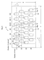
- Fig. 1 is a plan view showing a printing head in one embodiment of the present invention
- Fig. 2 is the bottom view of Fig. 1.
- Fig. 3 is a sectional view taken along the line Z-Z in Fig. 1.
- a printing head (liquid discharge device) 31 is composed of a piezoelectric actuator 11 and a flow passage member 21.
- the flow passage member 21 has a plurality of liquid compressing chambers 23 with liquid outlet orifices 22.
- the piezoelectric actuator 11 is bonded on the flow passage member 21 with an adhesive layer 25, so that driving electrodes 15 correspond in position to the liquid compressing chambers 23.
- the piezoelectric actuator 11 is composed of a laminated body wherein a common electrode 13, a piezoelectric ceramic layer 14 and driving electrodes 15 are laminated on a diaphragm 12 in this order. By taking this form, large displacement can be obtained, even if d 31 vibration mode is used. As shown in Fig. 1, a land part 15a is prepared at one end of each driving electrode 15 so that external wiring can be connected to apply driving voltage. Each liquid compressing chamber 23 is separated by a partition wall 24.
- a plurality of piezoelectric displacement elements 16 that are composed of the common electrode 13, the driving electrode 15 and the piezoelectric ceramic layer 14 positioned between these electrodes, are longitudinally and laterally disposed in hound's-tooth check pattern.
- Each liquid compressing chamber 23 in the flow passage member 21 is disposed in the position corresponding to each piezoelectric displacement element 16.
- the liquid outlet orifice 22 is formed in the approximately central vicinity of each liquid compressing chamber 23. As shown in Fig. 2, the liquid outlet orifices 22 are longitudinally and laterally disposed in hound's-tooth check pattern on the bottom side of the printing head 31.
- each piezoelectric displacement element 16 is flexibly transformed together with the diaphragm 12 to apply pressure on the inside of the liquid compressing chamber 23.
- ink that is introduced into the liquid compressing chamber 23 through the liquid inlet orifice (not shown in the figures) is pressured, so that a drop of ink can be discharged from the liquid outlet orifice 22.
- the printing head 31 is applicable to both serial scan head and line scan head.
- longitudinal direction (direction S) and its opposite direction are main-scanning direction of the printing head 31.
- Sub-scanning direction (direction t) which is vertical to the main-scanning direction is a scanning direction of recording medium (e.g. printing paper).
- longitudinal direction is a main-scanning direction of recording medium, and the printing head 31 is fixed.
- the number of columns M may be properly set, depending on head type (serial scan head or line scan head), the maximum size of recording medium and the like.
- the number of lines N is not less than 4, preferably, 4 to 150.
- the liquid discharge device of the present invention is characterized in that the number of lines N of piezoelectric displacement elements is not less than 4; the resolution in lateral direction (dot density) is not less than 300 dpi, preferably, not less than 600 dpi ; the ratio (B/A) of arrangement interval B between the driving electrodes 15 in longitudinal direction to arrangement interval A between the driving electrodes 15 in lateral direction is 0.95 to 1.5; and further the minimum distance D between the neighboring driving electrodes 15 is 0.15A or more, that is D ⁇ 0.15A.
- “one scanning in longitudinal direction” means that in case of serial scan head, the printing head 31 scans once in direction S, while in case of line scan head, recording medium scans in direction S.
- the piezoelectric displacement elements 16 are disposed at the rate of 75 pieces/inch in each line. But according to variations in the number of lines N and/or in resolution in lateral direction, the piezoelectric displacement elements 16 can be disposed at a different rate in each line.
- the piezoelectric displacement elements 16 may be disposed preferably at the rate of 20 to 120 pieces/inch in each line, and more preferably at the rate of 20 to 90 pieces/inch. In this case, resolution in sub-scanning direction at which one scanning in direction S can print in each line is 20 dpi (dot interval 1.27 mm) to 90 dpi (dot interval 0.28 mm).
- the arrangement interval B between the driving electrodes 15 in longitudinal direction can be set, so that the value of the ratio (B/A) can be controlled within the above range.
- the arrangement interval B is excessively small, the piezoelectric displacement elements 16 in the neighboring line become too close, and thus influence of cross talk becomes larger.
- the arrangement interval B is excessively larger and the ratio of B/A is over 1.5, length of the printing head 31 in longitudinal direction becomes larger, and thus the printing head becomes larger, which makes handling and maintenance difficult.
- each driving electrode 15 is disposed so that the minimum distance D between the neighboring driving electrodes can keep 0.15A or more, that is D ⁇ 0.15A. This is because influence of cross talk can be smaller and miniaturization of a printing head can be achieved.
- the ratio of length Y in lateral direction to length X in longitudinal direction may be not less than 1.2, preferably, not less than 2. This can contribute to miniaturization of the printing head 31, even when a line scan head is composed of a plurality of piezoelectric actuators 11 disposed in sub-scanning direction that is vertical to the main-scanning direction of recording medium.
- the piezoelectric ceramic layer 14 can be made of a ceramic material that shows piezoelectricity, specifically Bi layered compound (layer perovskite compound), tungsten-bronze compound and a material containing perovskite compound such as Nb-based perovskite compound (e.g., alkali niobate coumpound (NAC) such as sodium niobate, and alkali earth niobate compound (NAEC) such as barium niobate), lead magnesium niobate (PMN-based compound), lead nickel niobate (PNN-based compound), lead zirconate titanate (PZT) containing Pb, and lead titanate.
- Nb-based perovskite compound e.g., alkali niobate coumpound (NAC) such as sodium niobate, and alkali earth niobate compound (NAEC) such as barium niobate
- a perovskite compound containing at least Pb is preferable.
- a material that contains lead magnesium niobate (PMN-based compound), lead nickel niobate (PNN-based compound), lead zirconate titanate (PZT) containing Pb and lead titanate is preferable.
- a crystal containing Pb as a constituent element at site A and containing Zr and Ti as constituent elements at site B is especially preferable.
- the piezoelectric ceramic layer 14 that has a high piezoelectric constant can be obtained.
- lead zirconate titanate containing Pb and lead titanate are preferable for adding large displacement.
- PbZrTiO 3 can be preferably used. It is possible to mix other oxides, and other elements as auxiliary components may be substituted at site A and/or site B as far as characteristics are not adversely affected. For example, solid solution of Pb(Zn 1/3 Sb 2/3 )O 3 and Pb(Ni 1/2 Te 1/2 )O 3 that have Zn, Sb, Ni and Te added as auxiliary components is preferable.
- an alkali earth element as the constituent element at site A in the above perovskite crystal.
- the alkali earth element include Ba, Sr and Ca, and in particular Ba and Sr are preferable in achieving greater displacement. Consequently, relative dielectric constant is improved, thus making it possible to obtain a higher piezoelectric constant.
- thickness of the piezoelectric ceramic layer 14 is not limited specifically, it may be not more than 30 ⁇ m, preferably not more than 20 ⁇ m and more preferably 8 to 15 ⁇ m.
- material of the diaphragm 12 is not limited specifically, for example, metal elements such as molybdenum, tungsten, tantalum, titanium, platinum, iron and nickel, metal alloys of these metals, metal materials such as stainless steel, or ceramics such as zirconia and PZT can be used.
- metal elements such as molybdenum, tungsten, tantalum, titanium, platinum, iron and nickel, metal alloys of these metals, metal materials such as stainless steel, or ceramics such as zirconia and PZT can be used.
- the diaphragm 12 and the piezoelectric ceramic layer 14 are composed of the same material.
- the diaphragm 12 is fired and united with the common electrode 13 and the piezoelectric ceramic layer 14. Thus, curvative deformation caused in the piezoelectric ceramic layer 14 can be corrected.
- the common electrode 13 As a material of the common electrode 13, one or a combination of not less than two selected from Ag, Pd, Pt, Rh, Au and Ni-based materials are preferably used. In particular, Ag-Pd based alloy is more preferable. Thickness of the common electrode 13 has conducting properties and preferably it is not so large as to prevent displacement, e.g. 0.5 to 8 ⁇ m, more preferably 1 to 3 ⁇ m.
- the same metals as in the above-mentioned common electrode 13 can be used.
- Au that is excellent in electric resistance and corrosion resistance is used.
- Thickness of the driving electrode 15 and the land part 15a is 0.3 to 5 ⁇ m, preferably 0.5 to 2 ⁇ m.
- total thickness of the piezoelectric actuator 11 is not limited specifically, it may be not more than 100 ⁇ m, preferably not more than 80 ⁇ m, more preferably not more than 65 ⁇ m and most preferably not more than 50 ⁇ m.
- the lower limit of thickness is 3 ⁇ m, preferably 5 ⁇ m, more preferably 10 ⁇ m and most preferably 20 ⁇ m so as to achieve sufficient mechanical strength to prevent breakage during handling and operation.
- the method of manufacturing the piezoelectric actuator 11 will be now described. First, using powder of the piezoelectric ceramics, a required number of green sheets are formed. On the approximately whole surface of some green sheets, common electrode patterns are formed. A laminated body is formed by laminating green sheets so that the common electrode patterns can be interposed between the green sheets with the common electrode patterns formed and other green sheets. Then, after cutting this laminated body in a predetermined form, the main body of the piezoelectric actuator is formed by firing at 900 to 1100°C. Lastly, a conductive paste is printed on the surface of this piezoelectric actuator to form driving electrode patterns and land part patterns in a predetermined position, and firing is performed at 600 to 850°C. Thereby, the piezoelectric actuator 11 can be obtained. The driving electrode and the land part can be fired at the same time with the piezoelectric ceramic layer and the common electrode.
- the flow passage member 21 is obtained by rolling process.
- the liquid outlet orifice 22 and the liquid compressing chamber 23 are prepared by processing into a predetermined form with etching.
- this flow passage member 21 is made of at least one material selected from Fe-Cr, Fe-Ni, and WC-TiC based materials, and in particular, a material that is excellent in corrosion resistance against ink. Fe-Cr based material is more preferable.
- the piezoelectric actuator 11 and the flow passage member 21, for example, can be laminated and bonded via the adhesive layer 25.
- the adhesive layer 25 can be made of a well-known material. However, to avoid influence on the piezoelectric actuator 11 and the flow passage member 21, at least one thermosetting adhesive selected from epoxy resin, phenol resin and polyphenylene ether resin that have a thermosetting temperature of 100 to 250°C may be applicable. Using this adhesive layer 25, the piezoelectric actuator 11 and the flow passage member 21 can be bonded by heating the adhesive layer 25 to a thermosetting temperature. Thereby, the printing head 31 can be obtained.
- Fig. 4 is a plan view showing a printing head in another embodiment of the present invention.
- the printing head 41 has the same composition as the above-mentioned printing head 31, except that arrangement of the piezoelectric displacement elements is different.
- a plurality of piezoelectric displacement elements that is composed of the driving electrode 15, the common electrode and the piezoelectric ceramic layer 14 between these electrodes, are disposed longitudinally and laterally in hound's-tooth check pattern as shown in Fig. 4.
- the ratio(B/A) of arrangement interval B between the driving electrodes 15 in longitudinal direction to arrangement interval A between the driving electrodes 15 in lateral direction is 0.95 to 1.5.
- the minimum distance D between the neighboring driving electrodes 15 keeps 0.15A or more, that is D ⁇ 0.15A.
- description is omitted, putting the same symbols as in Fig. 1.
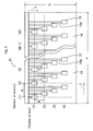
- Fig. 5 is a plan view showing a printing head in the other embodiment of the present invention.
- the extraction electrodes 15b for applying driving voltage are respectively connected to one end of the driving electrode 15.
- Each extraction electrode 15b is extended to the end of the piezoelectric actuator 11. Thereby external wiring is facilitated.
- the ratio (B/A) and the minimum distance D satisfy the above-mentioned conditions.
- description is omitted, putting the same symbols as in Fig. 1.
- the extraction electrodes are extended to the end of the piezoelectric actuator as shown in Fig. 5, for example, it is preferable that approximately half of the extraction electrodes are extended to the one end of the piezoelectric actuator, while the rest of the extraction electrodes to the other end of the piezoelectric actuator.
- cross talk that results from the extraction electrodes can be suppressed and the interval between the neighboring piezoelectric displacement elements becomes small, which can contribute to miniaturization of printing heads.
- Fig. 6 is a plan view showing a printing head in the other embodiment of the present invention.
- the printing head 61 has the same composition as the above-mentioned printing head 31, except that arrangement of the piezoelectric displacement elements is different.
- a plurality of piezoelectric displacement elements are disposed longitudinally and laterally in lattice pattern as shown in Fig. 6.
- the ratio (B/A) and the minimum distance D satisfy the above-mentioned conditions.
- description is omitted, putting the same symbols as in Fig. 1.
- the piezoelectric actuator is a laminated body wherein the common electrode, the piezoelectric ceramic layer, and the driving electrode are laminated on the diaphragm in this order.
- conductor layers and piezoelectric ceramic layers may be laminated one by one or in plural layers each.
- the conductor layers and the common electrodes are electrically connected. This makes it possible to lower electricity loss caused by piezoelectric vibration of the diaphragm that is induced and generated by displacement of the piezoelectric ceramic layer.
- the conductor layer, the common electrode and the piezoelectric ceramic layer are disposed symmetrically along the thickness direction of the laminated body. Thereby, warp during firing can be prevented.
- the liquid discharge device of the present invention is applied to a printing head.
- the liquid discharge device of the present invention is applicable to, for example, pumps that are used to precisely discharge and transfer liquid such as adhesive and ink.
- piezoelectric ceramics powder containing lead zirconate titanate having purity of not less than 99.9% was prepared and mill-ground by the use of a zirconia ball of its diameter ⁇ 2 mm and adjusted so that the mean particle size can be 0.3 to 0.5 ⁇ m. After drying, material powder was obtained by passing through mesh.
- a liquid discharge device printing head
- Liquid compressing chambers of the flow passage member were disposed so as to correspond in position to piezoelectric displacement elements of the piezoelectric actuator.
- the flow passage member was made up of SUS316. The piezoelectric actuator and the flow passage member were bonded, using epoxy adhesive and heating at 150°C for four hours.
- each liquid discharge device performance evaluation was conducted as follows. Using each liquid discharge device, while a drop of liquid was continuously discharged, discharge speed of liquid drop was checked. Specifically, by providing electricity of 10kHz drive frequency and 30V voltage between driving electrode and common electrode of the piezoelectric actuator, liquid in the liquid compressing chambers was compressed. Discharge speed of liquid drop from liquid outlet orifices was measured by a high-speed video camera and a stroboscope. Discharge speed was calculated as follows: when the luminescence interval of the stroboscope is taken to be, for example, 1 second, the distance of how far liquid drop moved was measured on the monitor image taken by a video camera; and the obtained distance was divided by the luminescence interval.
- Cross talk influence mentioned in Table 1 was evaluated, based on rate of change of the discharge speeds, that is, the following discharge speed measured as mentioned in the above; (1) the discharge speed when all piezoelectric displacement elements were driven at the same time; and (2) the discharge speed when one piezoelectric displacement element was driven alone.
- the rate of change was calculated as follows: the discharge speed when all piezoelectric displacement elements were driven was subtracted from the discharge speed when one piezoelectric displacement element was driven alone; and the value so obtained was divided by the discharge speed when one piezoelectric displacement element was driven alone, and then multiplied by 100.
- “Cross talk influence” of Table 1 " ⁇ " was marked when the rate of change so obtained was not more than 15%, and " ⁇ ” was marked when the rate of change so obtained was not less than 16%.
- the overall evaluation was mentioned in "Evaluation”. The results are presented in Table 1.
- the samples Nos. 1, 7, 13, 14, 23 and 29 that are out of the scope of the present invention showed a large value of not less than 16% in the rate of change of discharge speed, and cross talk had large influence.
- the sample No. 22 had the ratio (B/A) of over 1.5, making it impossible to miniaturize printing heads.
- the samples Nos. 2 to 6, Nos. 8 to 12, Nos. 15 to 22, Nos. 24 to 28 and Nos. 30 to 35 that are within the scope of the present invention showed a small value of not more than 15% in the rate of change of discharge speed, and cross talk had small influence.
- the samples Nos. 2 to 5, Nos. 8 to 11, Nos. 15 to 21, Nos. 24 to 27 and Nos. 30 to 35 showed a value of not less than 1.2 in the ratio (Y/X) of length Y in lateral direction to length X in longitudinal direction of the piezoelectric actuator, which can contribute to further miniaturization of printing heads.
Landscapes
- Particle Formation And Scattering Control In Inkjet Printers (AREA)
- Reciprocating Pumps (AREA)
Abstract
Description
(In the above formula, 0≦x≦0.1,
0.1≦y≦90,
0.1≦a≦90.05,
0.002≦b≦0.01,
0.44≦c≦0.50,
α=0.1~1.0)
may be used. Though thickness of the piezoelectric


Claims (13)
- A liquid discharge device comprising a piezoelectric actuator in which a plurality of piezoelectric displacement elements with a plurality of driving electrodes formed on a piezoelectric ceramic layer are longitudinally and laterally disposed with regularity; and
a flow passage member in which a plurality of liquid compressing chambers with liquid outlet orifices are formed, and on which the piezoelectric actuator is placed, so that the driving electrodes correspond in position to the liquid compressing chambers,
wherein the piezoelectric displacement elements are disposed longitudinally in N lines (N≧4), having dot density of not less than 300 dpi in the lateral direction, showing 0.95 to 1.5 in the ratio (B/A) of arrangement interval B between the driving electrodes in the longitudinal direction to arrangement interval A between the driving electrodes in the lateral direction, and showing D≧0.15A in the minimum distance D between the neighboring driving electrodes. - The liquid discharge device according to claim 1, wherein dot density is not less than 600 dpi in the lateral direction.
- The liquid discharge device according to claim 1, wherein the piezoelectric displacement elements are disposed longitudinally in number of lines N of 4 to 150.
- The liquid discharge device according to claim 1, wherein the piezoelectric displacement elements are disposed at a rate of 20 to 120 pieces/inch in each line.
- The liquid discharge device according to claim 4, wherein the piezoelectric displacement elements are disposed at a rate of 20 to 90 pieces/inch in each line.
- The liquid discharge device according to claim 1,
wherein the piezoelectric displacement elements are disposed in hound's-tooth check pattern and in the piezoelectric actuator the ratio (Y/X) of length Y in the lateral direction to length X in the longitudinal direction is not less than 1.2. - The liquid discharge device according to claim 6, having the ratio (Y/X) of not less than 2.
- The liquid discharge device according to claim 1,
wherein the piezoelectric actuator comprises a laminated body in which a common electrode, a piezoelectric ceramic layer and driving electrodes are laminated on a diaphragm in this order; and
the piezoelectric displacement elements comprises the common electrode, the driving electrode and the piezoelectric ceramic layer between these electrodes. - The liquid discharge device according to claim 1, wherein a land part is prepared at one end of each driving electrode to connect external wiring for applying driving voltage.
- The liquid discharge device according to claim 1, applied to a serial scan head.
- The liquid discharge device according to claim 1, applied to a line scan head.
- Recording apparatus having the liquid discharge device according to claim 1.
- An ink-jet printing head comprising a piezoelectric actuator in which a plurality of piezoelectric displacement elements with a plurality of driving electrodes formed on a piezoelectric ceramic layer are longitudinally and laterally disposed with regularity; and
a flow passage member in which a plurality of liquid compressing chambers with liquid outlet orifices are formed, and on which the piezoelectric actuator is placed, so that the driving electrodes correspond in position to the liquid compressing chambers,
wherein the piezoelectric displacement elements are disposed longitudinally in N lines (N≧4), having dot density of not less than 300 dpi in the lateral direction, showing 0.95 to 1.5 in the ratio (B/A) of arrangement interval B between the driving electrodes in the longitudinal direction to arrangement interval A between the driving electrodes in the lateral direction, and showing D≧0.15A in the minimum distance D between the neighboring driving electrodes.
Applications Claiming Priority (2)
| Application Number | Priority Date | Filing Date | Title |
|---|---|---|---|
| JP2004103874 | 2004-03-31 | ||
| JP2004103874 | 2004-03-31 |
Publications (3)
| Publication Number | Publication Date |
|---|---|
| EP1582353A2 true EP1582353A2 (en) | 2005-10-05 |
| EP1582353A3 EP1582353A3 (en) | 2006-11-08 |
| EP1582353B1 EP1582353B1 (en) | 2008-12-31 |
Family
ID=34880041
Family Applications (1)
| Application Number | Title | Priority Date | Filing Date |
|---|---|---|---|
| EP05006993A Expired - Lifetime EP1582353B1 (en) | 2004-03-31 | 2005-03-31 | Liquid discharge device, recording apparatus, and ink-jet print head |
Country Status (4)
| Country | Link |
|---|---|
| US (1) | US7517062B2 (en) |
| EP (1) | EP1582353B1 (en) |
| CN (1) | CN100579779C (en) |
| DE (1) | DE602005012008D1 (en) |
Families Citing this family (5)
| Publication number | Priority date | Publication date | Assignee | Title |
|---|---|---|---|---|
| CN103561956B (en) * | 2011-06-29 | 2016-01-06 | 京瓷株式会社 | Liquid ejection head and recording device using same |
| JP5783849B2 (en) * | 2011-08-26 | 2015-09-24 | 京セラ株式会社 | Liquid discharge head and recording apparatus using the same |
| EP2832544B1 (en) * | 2012-03-27 | 2020-11-18 | Kyocera Corporation | Method for driving liquid-discharging head and recording device |
| CN104334498B (en) * | 2012-04-16 | 2016-12-21 | 佳能株式会社 | Sodium niobate powder and its preparation method, ceramic preparation method and piezoelectric element |
| GB2566868B (en) * | 2016-06-14 | 2021-07-28 | Shanghai Realfast Digital Tech Co Ltd | Inkjet printhead with multiple aligned drop ejectors and methods of use thereof for printing |
Citations (4)
| Publication number | Priority date | Publication date | Assignee | Title |
|---|---|---|---|---|
| WO1997028000A1 (en) | 1996-02-01 | 1997-08-07 | Spectra, Inc. | High resolution matrix ink jet arrangement |
| JPH1134321A (en) | 1997-07-17 | 1999-02-09 | Mita Ind Co Ltd | Ink jet head |
| JP2003154646A (en) | 2001-11-21 | 2003-05-27 | Matsushita Electric Ind Co Ltd | Inkjet head |
| JP2004103874A (en) | 2002-09-10 | 2004-04-02 | Matsushita Electric Ind Co Ltd | Fan unit in housing of electric device and electric device equipped with the fan unit |
Family Cites Families (7)
| Publication number | Priority date | Publication date | Assignee | Title |
|---|---|---|---|---|
| US5146236A (en) * | 1989-12-14 | 1992-09-08 | Ricoh Company, Ltd. | Ink jet record apparatus |
| US5455615A (en) * | 1992-06-04 | 1995-10-03 | Tektronix, Inc. | Multiple-orifice drop-on-demand ink jet print head having improved purging and jetting performance |
| GB9713872D0 (en) * | 1997-07-02 | 1997-09-03 | Xaar Ltd | Droplet deposition apparatus |
| DE60128506T2 (en) * | 2000-03-21 | 2008-01-31 | Fuji Xerox Co., Ltd. | ink-jet head |
| JP4362996B2 (en) * | 2001-08-22 | 2009-11-11 | 富士ゼロックス株式会社 | Piezoelectric / electrostrictive actuator having lattice arrangement and manufacturing method thereof |
| EP1477316B1 (en) * | 2002-02-19 | 2008-05-14 | Brother Kogyo Kabushiki Kaisha | Ink jet head and ink jet printer |
| US7303259B2 (en) * | 2003-12-30 | 2007-12-04 | Fujifilm Dimatix, Inc. | Drop ejection assembly |
-
2005
- 2005-03-30 CN CN200510062779A patent/CN100579779C/en not_active Expired - Lifetime
- 2005-03-31 EP EP05006993A patent/EP1582353B1/en not_active Expired - Lifetime
- 2005-03-31 DE DE602005012008T patent/DE602005012008D1/en not_active Expired - Lifetime
- 2005-03-31 US US11/096,710 patent/US7517062B2/en not_active Expired - Lifetime
Patent Citations (4)
| Publication number | Priority date | Publication date | Assignee | Title |
|---|---|---|---|---|
| WO1997028000A1 (en) | 1996-02-01 | 1997-08-07 | Spectra, Inc. | High resolution matrix ink jet arrangement |
| JPH1134321A (en) | 1997-07-17 | 1999-02-09 | Mita Ind Co Ltd | Ink jet head |
| JP2003154646A (en) | 2001-11-21 | 2003-05-27 | Matsushita Electric Ind Co Ltd | Inkjet head |
| JP2004103874A (en) | 2002-09-10 | 2004-04-02 | Matsushita Electric Ind Co Ltd | Fan unit in housing of electric device and electric device equipped with the fan unit |
Also Published As
| Publication number | Publication date |
|---|---|
| US7517062B2 (en) | 2009-04-14 |
| EP1582353A3 (en) | 2006-11-08 |
| EP1582353B1 (en) | 2008-12-31 |
| US20050248625A1 (en) | 2005-11-10 |
| CN100579779C (en) | 2010-01-13 |
| DE602005012008D1 (en) | 2009-02-12 |
| CN1676332A (en) | 2005-10-05 |
Similar Documents
| Publication | Publication Date | Title |
|---|---|---|
| US6891316B2 (en) | Laminated piezoelectric element, actuator and printing head | |
| JP2007097280A (en) | Piezoelectric actuator, manufacturing method thereof, and ink jet recording head | |
| JP6483525B2 (en) | Piezoelectric element, piezoelectric member using the same, liquid discharge head, and recording apparatus | |
| EP1582353A2 (en) | Liquid discharge device | |
| JP5458085B2 (en) | Multilayer piezoelectric body, piezoelectric actuator and print head | |
| JP4812244B2 (en) | Print head | |
| JP2006187188A (en) | Piezoelectric actuator and liquid ejection device | |
| JP5260900B2 (en) | Liquid discharge head | |
| JP4991145B2 (en) | Inspection method of piezoelectric actuator | |
| JP2005041053A (en) | Liquid ejection device | |
| EP0734865A2 (en) | Ink jet print head | |
| JP4307161B2 (en) | Print head and electronic equipment | |
| JP5096659B2 (en) | Piezoelectric actuator and print head | |
| JP4456357B2 (en) | Piezoelectric actuator and inkjet recording head | |
| JP4833510B2 (en) | Ink jet recording head and manufacturing method thereof | |
| JP2005159042A (en) | Piezoelectric actuator and liquid ejection device | |
| JP4445719B2 (en) | Piezoelectric actuator and inkjet recording head | |
| JP2005313629A (en) | Liquid ejection device | |
| JP4766827B2 (en) | Method for manufacturing piezoelectric laminate | |
| JP4593905B2 (en) | Piezoelectric actuator, manufacturing method thereof, and liquid ejection device | |
| JP2005244091A (en) | Piezoelectric laminate, piezoelectric actuator, print head and printing machine | |
| JP2005021779A (en) | Piezoelectric actuator and liquid ejection apparatus having the same | |
| JP2005021771A (en) | Piezoelectric actuator, liquid ejection device, and electronic device | |
| JP2006073672A (en) | Multilayer piezoelectric body, manufacturing method thereof, piezoelectric actuator, and print head | |
| JP4703167B2 (en) | Liquid ejection device |
Legal Events
| Date | Code | Title | Description |
|---|---|---|---|
| PUAI | Public reference made under article 153(3) epc to a published international application that has entered the european phase |
Free format text: ORIGINAL CODE: 0009012 |
|
| AK | Designated contracting states |
Kind code of ref document: A2 Designated state(s): AT BE BG CH CY CZ DE DK EE ES FI FR GB GR HU IE IS IT LI LT LU MC NL PL PT RO SE SI SK TR |
|
| AX | Request for extension of the european patent |
Extension state: AL BA HR LV MK YU |
|
| PUAL | Search report despatched |
Free format text: ORIGINAL CODE: 0009013 |
|
| AK | Designated contracting states |
Kind code of ref document: A3 Designated state(s): AT BE BG CH CY CZ DE DK EE ES FI FR GB GR HU IE IS IT LI LT LU MC NL PL PT RO SE SI SK TR |
|
| AX | Request for extension of the european patent |
Extension state: AL BA HR LV MK YU |
|
| 17P | Request for examination filed |
Effective date: 20070507 |
|
| AKX | Designation fees paid |
Designated state(s): DE FR GB |
|
| 17Q | First examination report despatched |
Effective date: 20070618 |
|
| RTI1 | Title (correction) |
Free format text: LIQUID DISCHARGE DEVICE, RECORDING APPARATUS, AND INK-JET PRINT HEAD |
|
| GRAP | Despatch of communication of intention to grant a patent |
Free format text: ORIGINAL CODE: EPIDOSNIGR1 |
|
| GRAS | Grant fee paid |
Free format text: ORIGINAL CODE: EPIDOSNIGR3 |
|
| GRAA | (expected) grant |
Free format text: ORIGINAL CODE: 0009210 |
|
| AK | Designated contracting states |
Kind code of ref document: B1 Designated state(s): DE FR GB |
|
| REG | Reference to a national code |
Ref country code: GB Ref legal event code: FG4D |
|
| REF | Corresponds to: |
Ref document number: 602005012008 Country of ref document: DE Date of ref document: 20090212 Kind code of ref document: P |
|
| PLBE | No opposition filed within time limit |
Free format text: ORIGINAL CODE: 0009261 |
|
| STAA | Information on the status of an ep patent application or granted ep patent |
Free format text: STATUS: NO OPPOSITION FILED WITHIN TIME LIMIT |
|
| 26N | No opposition filed |
Effective date: 20091001 |
|
| REG | Reference to a national code |
Ref country code: FR Ref legal event code: PLFP Year of fee payment: 11 |
|
| REG | Reference to a national code |
Ref country code: DE Ref legal event code: R082 Ref document number: 602005012008 Country of ref document: DE Representative=s name: VIERING, JENTSCHURA & PARTNER MBB PATENT- UND , DE |
|
| REG | Reference to a national code |
Ref country code: FR Ref legal event code: PLFP Year of fee payment: 12 |
|
| REG | Reference to a national code |
Ref country code: FR Ref legal event code: PLFP Year of fee payment: 13 |
|
| REG | Reference to a national code |
Ref country code: FR Ref legal event code: PLFP Year of fee payment: 14 |
|
| P01 | Opt-out of the competence of the unified patent court (upc) registered |
Effective date: 20230505 |
|
| PGFP | Annual fee paid to national office [announced via postgrant information from national office to epo] |
Ref country code: DE Payment date: 20240206 Year of fee payment: 20 Ref country code: GB Payment date: 20240208 Year of fee payment: 20 |
|
| PGFP | Annual fee paid to national office [announced via postgrant information from national office to epo] |
Ref country code: FR Payment date: 20240213 Year of fee payment: 20 |
|
| REG | Reference to a national code |
Ref country code: DE Ref legal event code: R071 Ref document number: 602005012008 Country of ref document: DE |
|
| REG | Reference to a national code |
Ref country code: GB Ref legal event code: PE20 Expiry date: 20250330 |
|
| PG25 | Lapsed in a contracting state [announced via postgrant information from national office to epo] |
Ref country code: GB Free format text: LAPSE BECAUSE OF EXPIRATION OF PROTECTION Effective date: 20250330 |