EP1582349A1 - Printing process and machine - Google Patents
Printing process and machine Download PDFInfo
- Publication number
- EP1582349A1 EP1582349A1 EP04007631A EP04007631A EP1582349A1 EP 1582349 A1 EP1582349 A1 EP 1582349A1 EP 04007631 A EP04007631 A EP 04007631A EP 04007631 A EP04007631 A EP 04007631A EP 1582349 A1 EP1582349 A1 EP 1582349A1
- Authority
- EP
- European Patent Office
- Prior art keywords
- cylinder
- printing
- printing cylinder
- chain
- speed
- Prior art date
- Legal status (The legal status is an assumption and is not a legal conclusion. Google has not performed a legal analysis and makes no representation as to the accuracy of the status listed.)
- Withdrawn
Links
- 238000007639 printing Methods 0.000 title claims abstract description 83
- 238000000034 method Methods 0.000 title claims description 20
- 239000000976 ink Substances 0.000 claims abstract 3
- 238000001035 drying Methods 0.000 claims description 5
- 230000001360 synchronised effect Effects 0.000 claims description 2
- 230000004048 modification Effects 0.000 claims 1
- 238000012986 modification Methods 0.000 claims 1
- 239000003086 colorant Substances 0.000 description 5
- 238000007650 screen-printing Methods 0.000 description 5
- 238000006073 displacement reaction Methods 0.000 description 1
- 230000000694 effects Effects 0.000 description 1
- 238000004519 manufacturing process Methods 0.000 description 1
- 238000002360 preparation method Methods 0.000 description 1
- 230000001105 regulatory effect Effects 0.000 description 1
Images
Classifications
-
- B—PERFORMING OPERATIONS; TRANSPORTING
- B41—PRINTING; LINING MACHINES; TYPEWRITERS; STAMPS
- B41F—PRINTING MACHINES OR PRESSES
- B41F21/00—Devices for conveying sheets through printing apparatus or machines
- B41F21/08—Combinations of endless conveyors and grippers
-
- B—PERFORMING OPERATIONS; TRANSPORTING
- B41—PRINTING; LINING MACHINES; TYPEWRITERS; STAMPS
- B41F—PRINTING MACHINES OR PRESSES
- B41F11/00—Rotary presses or machines having forme cylinders carrying a plurality of printing surfaces, or for performing letterpress, lithographic, or intaglio processes selectively or in combination
- B41F11/02—Rotary presses or machines having forme cylinders carrying a plurality of printing surfaces, or for performing letterpress, lithographic, or intaglio processes selectively or in combination for securities
-
- B—PERFORMING OPERATIONS; TRANSPORTING
- B41—PRINTING; LINING MACHINES; TYPEWRITERS; STAMPS
- B41F—PRINTING MACHINES OR PRESSES
- B41F15/00—Screen printers
- B41F15/08—Machines
- B41F15/0804—Machines for printing sheets
- B41F15/0809—Machines for printing sheets with cylindrical or belt-like screens
Definitions
- the present invention concerns a printing process for sheets of documents, such as securities, banknotes, checks, ID and passports.
- the present invention also concerns a printing machine suitable for carrying out the process according to the invention.
- Another printing machine is known for example from US patent 4,640,189, the content of which is incorporated by reference in the present application.
- This printing machine can print on both sides of a paper web either an image with juxtaposed colors by means of a typographic plate inked respectively by a collecting cylinder inked in turn by selective inking cylinders the number of which corresponds to the number of colors, or an image with superposed colors and designs by means of the plate cylinders substituted for the selective color inking cylinders and provided with printing plates inking a corresponding offset cylinder and of which the number corresponds to the number of colors and designs, or an image of each of the above-mentioned type.
- the machine comprises a first pair of blanket cylinders operating either as collecting cylinders each adapted to ink a cylinder carrying said typographic plate of which the image is transferred via an intermediate cylinder to another blanket cylinder of a second pair on the paper, or as offset cylinders contacting said other blanket cylinder, or operating one as collecting cylinder and the other as an offset cylinder.
- the paper passes between the blanket cylinders of the second pair.
- the idea of the present invention is to propose a printing system that needs less space to be implemented and also that is more efficient and quicker than the known printing systems.
- Figures 1 to 4 show in succession the preparation steps for the printing of a sheet while carried by a chain conveyor according to the present invention.
- Figure 5 show a top view of a printing cylinder according to the present invention.
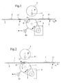
- a sheet 1 is transported by a chain conveyor 2 with a chain gripper system 3, as is well known in the art of printing machines.
- the chain conveyor 2 also passes between two cylinders, a printing cylinder 4 and a screen cylinder 5, both cylinders being used for the printing operation.
- the screen printing technique per se is known in the art, and reference is for example made to US 6,109,172 for the sake of completeness.
- the printing cylinder is driven by an independent motor 6 which is able to vary the rotational speed V pc of the printing cylinder.
- the printing cylinder 4 comprises at least one cylinder pit 7 with a leading edge 9 and a trailing edge 8 of the printing cylinder 4, said pit being intended to receive the chain gripper system 3 of the chain conveyor 2.
- the printing cylinder 4 is also subjected to vacuum air to maintain the sheet on the printing cylinder 4 during the printing operation.
- the suction air (vacuum) is created by a vacuum system with at least an aspiration pump 10 which is connected to ducts in the printing cylinder 4 to apply the suction air to the sheet 1 being printed.
- the screen cylinder 5 is moved away from the printing cylinder 4 when not in printing operation, with the doctor blade 11 being lifted to avoid damaging the screen, as represented.
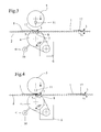
- the gripper 17 of the chain gripper system 3 is entering the pit 7 of the printing cylinder 4.
- the speed of the printing cylinder V pc is adjusted by regulating means acting on the motor 6, known per se in the art, such that the front side of the gripper is coordinated with the trailing edge 8 of the cylinder 4.
- the screen cylinder 5 and the doctor blade 11 preferably remain shifted away from the printing cylinder 4, for example lifted to avoid a collision with the chain gripper system 3.
- FIG 4 the beginning of the printing operation is shown.
- the screen cylinder 5 is brought into contact with the printing cylinder 4 and the doctor blade 11 is applied against the screen to carry out the printing operation per se on the sheet 1.
- the screen printing technique is known as such in the art of printing.
- the sheet is held by the chain gripper system 3 of the chain conveyor 2, and the sheet is further maintained against the printing cylinder 4 at the printing nip between cylinders 4 and 5 by the application of vacuum air through the surface of the printing cylinder 4.
- This technique is also known per se in the art.
- the printing speed that is the speed of rotation of both cylinders 4, 5 is slightly higher than the speed of the chain conveyor 2 to avoid production of misprints due to a speed difference between the chain gripper system 2 and the cylinders 4, 5 and maintain the proper relative position of gripper 17 and pit 7.
- the printing cylinder may also comprise more than one pit, for example two or three pits which would then correspond to successive chain grippers systems 3 on the chain conveyor 2. The principle indicated above would then be applicable to such configurations for each successive sheet.
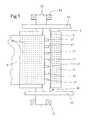
- a printing cylinder according the present invention is represented in top view in figure 5.
- the cylinder 4 comprises a pit 7 along its entire transversal length and is supported by an axis 12 held by bearings 13.
- the chain conveyor 2 comprises two parallel running chains 14, 15, running perpendicularly to the axis 12, said chains supporting the gripper system 16 per se and being situated on both sides of the cylinder 4.
- the chain gripper system 3 comprises several grippers 17 mounted on a chain gripper system 3 attached to the chains 14, 15 and said grippers 17 hold the sheet 1 to be printed.
- the chain gripper system 3 is known in the art of sheet transporting devices for printing machines.
- the printing cylinder 4 is linked to a vacuum system, schematically represented in figure 1 by pump 10 linked to series of holes 18 (see figure 5) to maintain the sheet 1 pressed against the cylinder 4 during the printing operation and allowing the cylinder 4 to drive the sheet 1 being printed at the cylinder speed V pc .
- This vacuum system is synchronized such that vacuum is applied to the sheet being printed only in the zone in which the printing is carried out. Accordingly, each row of holes parallel to the axis of the cylinder is subjected to vacuum in turn, depending on the position of the cylinder 4.
- the process according to the present invention is particularly advantageous to carry out a recto-verso silk-screen printing.
- drying unit may be an UV drying unit or other equivalent. Such a drying unit is particularly useful when carrying out a recto-verso printing of the sheets.
Landscapes
- Engineering & Computer Science (AREA)
- Mechanical Engineering (AREA)
- Supply, Installation And Extraction Of Printed Sheets Or Plates (AREA)
- Feeding Of Articles By Means Other Than Belts Or Rollers (AREA)
- Application Of Or Painting With Fluid Materials (AREA)
- Discharge By Other Means (AREA)
Abstract
The machine comprises at least a printing cylinder (4), an inking cylinder (5) and a chain gripper transporting system (2,3) with grippers (17). The printing cylinder (4) comprises at least one transversal pit (7) for receiving said chain gripper system (3) such that the inking cylinder (5) inks the planar object (1) while said object (1) is held by said chain gripper system (3).
Description
- The present invention concerns a printing process for sheets of documents, such as securities, banknotes, checks, ID and passports.
- The present invention also concerns a printing machine suitable for carrying out the process according to the invention.
- Printing processes and machines are known per se in the prior art. For example, US patent 4,574,696, the content of which is incorporated by reference in the present application, discloses a rotary printing press for the simultaneous multicolour printing on both sides of a web or sheet. The advantage of this machine consists in that it permits exploiting simultaneously two totally different methods for printing in a single pass an offset image on one side and an "Orlof" image on the other side, thus offering the user for the first time the possibility of printing notably safety backgrounds on both sides of a bank note through two different methods; this increases the safety against forgery and in addition makes printing operations more economical because the user is not compelled to use two separate machines.
- Another printing machine is known for example from US patent 4,640,189, the content of which is incorporated by reference in the present application. This printing machine can print on both sides of a paper web either an image with juxtaposed colors by means of a typographic plate inked respectively by a collecting cylinder inked in turn by selective inking cylinders the number of which corresponds to the number of colors, or an image with superposed colors and designs by means of the plate cylinders substituted for the selective color inking cylinders and provided with printing plates inking a corresponding offset cylinder and of which the number corresponds to the number of colors and designs, or an image of each of the above-mentioned type. For this purpose, the machine comprises a first pair of blanket cylinders operating either as collecting cylinders each adapted to ink a cylinder carrying said typographic plate of which the image is transferred via an intermediate cylinder to another blanket cylinder of a second pair on the paper, or as offset cylinders contacting said other blanket cylinder, or operating one as collecting cylinder and the other as an offset cylinder. In all cases, the paper passes between the blanket cylinders of the second pair.
- Another printing technique so called silk-screen printing is also known in the art. For example, US patent 6,109,172, the content of which is incorporated by reference in the present application, discloses a silk-screen printing machine with a printing cylinder engaging two stencil cylinders for printing at least two non-overlapping areas in different colors using the one printing cylinder.
- The idea of the present invention is to propose a printing system that needs less space to be implemented and also that is more efficient and quicker than the known printing systems.
- It is therefore an aim of the present invention to improve the known processes and machines.
- It is another aim of the present invention to provide a printing machine that can be built as a modular unit.
- It is a further aim of the present invention to provide a printing process and machine that are faster than the known one.
- To this effect, the invention is defined by the features of the claims.
- The invention will be best understood by the description of an exemplary embodiment and of the accompanying drawings in which
- Figures 1 to 4 show in succession the preparation steps for the printing of a sheet while carried by a chain conveyor according to the present invention.
- Figure 5 show a top view of a printing cylinder according to the present invention.
- As shown in figure 1, a
sheet 1 is transported by achain conveyor 2 with achain gripper system 3, as is well known in the art of printing machines. As schematically disclosed in this figure 1, thechain conveyor 2 also passes between two cylinders, aprinting cylinder 4 and ascreen cylinder 5, both cylinders being used for the printing operation. The screen printing technique per se is known in the art, and reference is for example made to US 6,109,172 for the sake of completeness. As represented, the printing cylinder is driven by anindependent motor 6 which is able to vary the rotational speed Vpc of the printing cylinder. Theprinting cylinder 4 comprises at least onecylinder pit 7 with a leadingedge 9 and atrailing edge 8 of theprinting cylinder 4, said pit being intended to receive thechain gripper system 3 of thechain conveyor 2. Theprinting cylinder 4 is also subjected to vacuum air to maintain the sheet on theprinting cylinder 4 during the printing operation. The suction air (vacuum) is created by a vacuum system with at least anaspiration pump 10 which is connected to ducts in theprinting cylinder 4 to apply the suction air to thesheet 1 being printed. - In addition, the
screen cylinder 5 is moved away from theprinting cylinder 4 when not in printing operation, with thedoctor blade 11 being lifted to avoid damaging the screen, as represented. - In figure 2, the
gripper 17 of thechain gripper system 3 is entering thepit 7 of theprinting cylinder 4. For avoiding a collision of the front side of thegripper 17 withtrailing edge 8 of thecylinder 4, the speed of the printing cylinder Vpc is adjusted by regulating means acting on themotor 6, known per se in the art, such that the front side of the gripper is coordinated with thetrailing edge 8 of thecylinder 4. During this operation, thescreen cylinder 5 and thedoctor blade 11 preferably remain shifted away from theprinting cylinder 4, for example lifted to avoid a collision with thechain gripper system 3. - In figure 3, the
chain gripper system 3 is now in thepit 7 of theprinting cylinder 4 and the speed of the cylinder Vpc is increased relatively to the speed of the chain gripper system Vc in order for the back side of thechain gripper system 3 to attain the leadingedge 9 of thecylinder 4. This is necessary to start the printing operation with a minimal white margin on thesheet 1. During the phase represented in figure 3, thedoctor blade 11 and the screen cylinder start going into position (i.e. downwards as represented in figure 3) to be able to carry out the printing operation. - In figure 4, the beginning of the printing operation is shown. As represented, the
screen cylinder 5 is brought into contact with theprinting cylinder 4 and thedoctor blade 11 is applied against the screen to carry out the printing operation per se on thesheet 1. The screen printing technique is known as such in the art of printing. During the entire printing step, the sheet is held by thechain gripper system 3 of thechain conveyor 2, and the sheet is further maintained against theprinting cylinder 4 at the printing nip betweencylinders printing cylinder 4. This technique is also known per se in the art. Preferably, the printing speed, that is the speed of rotation of bothcylinders chain conveyor 2 to avoid production of misprints due to a speed difference between thechain gripper system 2 and thecylinders gripper 17 andpit 7. - In order to carry out the displacement movements of
screen cylinder 5 andblade 11, it is possible to use numerous means such as excentrical systems, or pneumatically activated means, all well known in the art. - The printing cylinder may also comprise more than one pit, for example two or three pits which would then correspond to successive
chain grippers systems 3 on thechain conveyor 2. The principle indicated above would then be applicable to such configurations for each successive sheet. - A printing cylinder according the present invention is represented in top view in figure 5. The
cylinder 4 comprises apit 7 along its entire transversal length and is supported by anaxis 12 held bybearings 13. Thechain conveyor 2 comprises twoparallel running chains axis 12, said chains supporting thegripper system 16 per se and being situated on both sides of thecylinder 4. Thechain gripper system 3 comprisesseveral grippers 17 mounted on achain gripper system 3 attached to thechains grippers 17 hold thesheet 1 to be printed. As such, thechain gripper system 3 is known in the art of sheet transporting devices for printing machines. - The
printing cylinder 4, as mentioned above, is linked to a vacuum system, schematically represented in figure 1 bypump 10 linked to series of holes 18 (see figure 5) to maintain thesheet 1 pressed against thecylinder 4 during the printing operation and allowing thecylinder 4 to drive thesheet 1 being printed at the cylinder speed Vpc. - This vacuum system is synchronized such that vacuum is applied to the sheet being printed only in the zone in which the printing is carried out. Accordingly, each row of holes parallel to the axis of the cylinder is subjected to vacuum in turn, depending on the position of the
cylinder 4. - The process according to the present invention is particularly advantageous to carry out a recto-verso silk-screen printing.
- Depending on the configuration of the machine, it can be useful to add a drying unit to dry the printed sheets. The drying unit maybe an UV drying unit or other equivalent. Such a drying unit is particularly useful when carrying out a recto-verso printing of the sheets.
Claims (12)
- Process for printing successive sheets of documents, such as securities, banknotes, checks, ID and passports, in which said sheets are transported by a chain gripper system comprising successive grippers attached to two parallel chains and a printing unit, wherein the successive sheets are printed in said printing unit while being held by the chain gripper system.
- A process as claimed in claim 1, wherein the printing unit comprises a printing cylinder and a silk-screen cylinder, said printing cylinder comprising at least a cylinder pit for receiving a gripper of said chain gripper system.
- A process as claimed in claim 1 or 2, wherein the chain gripper system has a chain speed Vc, the printing cylinder has a printing cylinder speed Vpc, wherein both speeds are synchronized such that a gripper enters said printing cylinder pit at the trailing edge of said cylinder, wherein said speeds are then relatively modified such that said gripper arrives at a leading end of said cylinder when said screen cylinder starts to deposit ink on the sheet being printed.
- A process as claimed in claim 3, wherein said relative modification of speed comprises an increase of the printing cylinder speed Vpc.
- A process as claimed in one of claims 1 to 4, wherein the speed of the printing cylinder and of the inking cylinder is slightly higher than the chain speed Vc during the printing operation.
- A process as claimed in one of claims 2 to 5, wherein the inking cylinder is shifted away from the printing cylinder to allow the cylinder pit to receive the gripper and the inking cylinder is shifted towards the printing cylinder to allow the printing operation.
- A process as claimed in one of claims 1 to 6, wherein during the printing operation, the sheet is maintained against the printing cylinder by vacuum.
- A printing machine for planar objects (1) such as sheets, securities, banknotes, checks, ID and passports and other similar documents, comprising at least a printing cylinder (4), an inking cylinder (5) and a chain gripper transporting system (2,3,14,15,16) with grippers (17), wherein the printing cylinder (4) comprises at least one transversal pit (7) for receiving said chain gripper system (3) such that the inking cylinder (5) inks the planar object (1) while said object (1) is held by said chain gripper system (3).
- A machine according to claim 8, wherein said printing cylinder (4) is driven by an independent motor (6).
- A machine according to claim 8 or 9, wherein said inking cylinder (5) is shiftable towards and away from the printing cylinder (4) by shifting means to allow the chain gripper system (3) to enter in said pit (7) before printing.
- A machine according to one of claims 8 to 10, further comprising an aspiration system (10,18) for applying vacuum to the printing cylinder (4).
- A machine according to one of claims 8 to 11, further comprising at least one drying unit.
Priority Applications (8)
| Application Number | Priority Date | Filing Date | Title |
|---|---|---|---|
| EP04007631A EP1582349A1 (en) | 2004-03-30 | 2004-03-30 | Printing process and machine |
| CN200580008841.6A CN100496976C (en) | 2004-03-30 | 2005-03-23 | Printing method and printing machine |
| AT05708789T ATE396869T1 (en) | 2004-03-30 | 2005-03-23 | PRINTING METHOD AND MACHINE |
| US10/591,139 US7677171B2 (en) | 2004-03-30 | 2005-03-23 | Printing machine and process for printing including a chain gripper system |
| DE602005007197T DE602005007197D1 (en) | 2004-03-30 | 2005-03-23 | PRINTING METHOD AND MACHINE |
| PCT/IB2005/000787 WO2005095109A1 (en) | 2004-03-30 | 2005-03-23 | Printing process and machine |
| JP2007505653A JP4885840B2 (en) | 2004-03-30 | 2005-03-23 | Printing method and printing machine |
| EP05708789A EP1729962B1 (en) | 2004-03-30 | 2005-03-23 | Printing process and machine |
Applications Claiming Priority (1)
| Application Number | Priority Date | Filing Date | Title |
|---|---|---|---|
| EP04007631A EP1582349A1 (en) | 2004-03-30 | 2004-03-30 | Printing process and machine |
Publications (1)
| Publication Number | Publication Date |
|---|---|
| EP1582349A1 true EP1582349A1 (en) | 2005-10-05 |
Family
ID=34878200
Family Applications (2)
| Application Number | Title | Priority Date | Filing Date |
|---|---|---|---|
| EP04007631A Withdrawn EP1582349A1 (en) | 2004-03-30 | 2004-03-30 | Printing process and machine |
| EP05708789A Expired - Lifetime EP1729962B1 (en) | 2004-03-30 | 2005-03-23 | Printing process and machine |
Family Applications After (1)
| Application Number | Title | Priority Date | Filing Date |
|---|---|---|---|
| EP05708789A Expired - Lifetime EP1729962B1 (en) | 2004-03-30 | 2005-03-23 | Printing process and machine |
Country Status (7)
| Country | Link |
|---|---|
| US (1) | US7677171B2 (en) |
| EP (2) | EP1582349A1 (en) |
| JP (1) | JP4885840B2 (en) |
| CN (1) | CN100496976C (en) |
| AT (1) | ATE396869T1 (en) |
| DE (1) | DE602005007197D1 (en) |
| WO (1) | WO2005095109A1 (en) |
Cited By (4)
| Publication number | Priority date | Publication date | Assignee | Title |
|---|---|---|---|---|
| WO2007119167A3 (en) * | 2006-04-19 | 2008-05-08 | Pont Massimiliano Dal | Printing apparatus |
| WO2011018243A1 (en) * | 2009-08-14 | 2011-02-17 | Zyrus Beteiligungsgesellschaft Mbh & Co. Patente I Kg | Rotary screen printing device and method |
| EP3210777A4 (en) * | 2014-10-23 | 2018-04-11 | Komori Corporation | Rotary screen printer |
| WO2018153509A1 (en) * | 2017-02-23 | 2018-08-30 | Koenig & Bauer Ag | Method and device for operating a rotary screen-printing machine |
Families Citing this family (8)
| Publication number | Priority date | Publication date | Assignee | Title |
|---|---|---|---|---|
| EP1961559A1 (en) | 2007-02-20 | 2008-08-27 | Kba-Giori S.A. | Cylinder body for orienting magnetic flakes contained in an ink or varnish vehicle applied on a sheet-like or web-like substrate |
| EP1990208A1 (en) | 2007-05-10 | 2008-11-12 | Kba-Giori S.A. | Device and method for magnetically transferring indica to a coating composition applied to a substrate |
| ES2540864T3 (en) | 2010-09-24 | 2015-07-14 | Kba-Notasys Sa | System and method for orienting magnetic flakes or lamellae contained in an ink or varnish vehicle applied on a sheet-shaped or band-shaped substrate |
| HK1231436A1 (en) | 2014-08-22 | 2017-12-22 | 锡克拜控股有限公司 | Apparatus and method for producing optical effect layers |
| JP6358702B2 (en) * | 2014-10-23 | 2018-07-18 | 株式会社小森コーポレーション | Rotary screen printing machine |
| JP7098860B2 (en) | 2017-01-31 | 2022-07-12 | シクパ ホルディング ソシエテ アノニム | Equipment and methods for making optical effect layers |
| CN108749277A (en) * | 2018-04-13 | 2018-11-06 | 如皋市中罗印刷机械有限公司 | Direct printing device and using method thereof |
| JP7419897B2 (en) | 2020-03-16 | 2024-01-23 | 富士フイルムビジネスイノベーション株式会社 | Image forming device |
Citations (6)
| Publication number | Priority date | Publication date | Assignee | Title |
|---|---|---|---|---|
| GB2277903A (en) * | 1993-05-12 | 1994-11-16 | Deritend Eng Ltd | Changing roller-mounted printing plates |
| US5477780A (en) * | 1992-06-23 | 1995-12-26 | Keller; James J. | Horizontal sheet transfer multiple color offset rotary printing press with horizontal slide access |
| GB2314834A (en) * | 1996-06-29 | 1998-01-14 | Crabtree Gateshead Ltd | Sheet registration |
| DE19703312A1 (en) * | 1997-01-30 | 1998-08-06 | Rk Siebdrucktechnik Gmbh | Process for controlling a screen printing cylinder machine |
| WO1998053996A1 (en) * | 1997-05-28 | 1998-12-03 | Stork Screens B.V. | Method and device for in-register conveying of sheets in a printing machine |
| US20020063382A1 (en) * | 2000-11-30 | 2002-05-30 | Hendrik Frank | Apparatus for synchronizing transfers of sheet material |
Family Cites Families (11)
| Publication number | Priority date | Publication date | Assignee | Title |
|---|---|---|---|---|
| US3664261A (en) * | 1968-06-17 | 1972-05-23 | Harold P Dahlgren | Straight feed press |
| DD114373A1 (en) * | 1974-01-23 | 1975-08-05 | ||
| DE3117856A1 (en) * | 1981-05-06 | 1982-12-02 | M.A.N.- Roland Druckmaschinen AG, 6050 Offenbach | COVER PRINTING IN THE BOOM OF AN ARC ROTATION PRINTING MACHINE |
| DE3473745D1 (en) * | 1983-07-26 | 1988-10-06 | De La Rue Giori Sa | Perfecting rotary multicolour printing machine |
| ATE39087T1 (en) * | 1983-07-26 | 1988-12-15 | De La Rue Giori Sa | ROTARY MULTICOLOR PRINTING PRESS. |
| JPS6044349A (en) * | 1983-08-23 | 1985-03-09 | Dainippon Ink & Chem Inc | Sheet-fed offset rotary printer |
| DE9007513U1 (en) * | 1990-04-24 | 1992-03-12 | Heidelberger Druckmaschinen Ag, 6900 Heidelberg | Sheet guiding device in the delivery area of a sheet-fed rotary printing press |
| JPH06143540A (en) * | 1992-11-02 | 1994-05-24 | Shinano Kenshi Kk | Multicolor printer |
| DE19525635C2 (en) * | 1995-07-14 | 1998-01-29 | Heidelberger Druckmasch Ag | Device for sheet delivery in a sheet printing machine |
| RU2157764C2 (en) * | 1995-10-20 | 2000-10-20 | Де ля Рю Жиори С.А. | Sheet-fed machine |
| WO1997034767A1 (en) * | 1996-03-21 | 1997-09-25 | De La Rue Giori S.A. | Silk-screen printing machine |
-
2004
- 2004-03-30 EP EP04007631A patent/EP1582349A1/en not_active Withdrawn
-
2005
- 2005-03-23 EP EP05708789A patent/EP1729962B1/en not_active Expired - Lifetime
- 2005-03-23 JP JP2007505653A patent/JP4885840B2/en not_active Expired - Fee Related
- 2005-03-23 US US10/591,139 patent/US7677171B2/en not_active Expired - Fee Related
- 2005-03-23 WO PCT/IB2005/000787 patent/WO2005095109A1/en not_active Ceased
- 2005-03-23 DE DE602005007197T patent/DE602005007197D1/en not_active Expired - Lifetime
- 2005-03-23 AT AT05708789T patent/ATE396869T1/en not_active IP Right Cessation
- 2005-03-23 CN CN200580008841.6A patent/CN100496976C/en not_active Expired - Fee Related
Patent Citations (6)
| Publication number | Priority date | Publication date | Assignee | Title |
|---|---|---|---|---|
| US5477780A (en) * | 1992-06-23 | 1995-12-26 | Keller; James J. | Horizontal sheet transfer multiple color offset rotary printing press with horizontal slide access |
| GB2277903A (en) * | 1993-05-12 | 1994-11-16 | Deritend Eng Ltd | Changing roller-mounted printing plates |
| GB2314834A (en) * | 1996-06-29 | 1998-01-14 | Crabtree Gateshead Ltd | Sheet registration |
| DE19703312A1 (en) * | 1997-01-30 | 1998-08-06 | Rk Siebdrucktechnik Gmbh | Process for controlling a screen printing cylinder machine |
| WO1998053996A1 (en) * | 1997-05-28 | 1998-12-03 | Stork Screens B.V. | Method and device for in-register conveying of sheets in a printing machine |
| US20020063382A1 (en) * | 2000-11-30 | 2002-05-30 | Hendrik Frank | Apparatus for synchronizing transfers of sheet material |
Cited By (7)
| Publication number | Priority date | Publication date | Assignee | Title |
|---|---|---|---|---|
| WO2007119167A3 (en) * | 2006-04-19 | 2008-05-08 | Pont Massimiliano Dal | Printing apparatus |
| EP2481584A1 (en) | 2006-04-19 | 2012-08-01 | Massimiliano Dal Pont | Printing apparatus |
| WO2011018243A1 (en) * | 2009-08-14 | 2011-02-17 | Zyrus Beteiligungsgesellschaft Mbh & Co. Patente I Kg | Rotary screen printing device and method |
| EP3210777A4 (en) * | 2014-10-23 | 2018-04-11 | Komori Corporation | Rotary screen printer |
| US10040276B2 (en) | 2014-10-23 | 2018-08-07 | Komori Corporation | Rotary screen printer |
| WO2018153509A1 (en) * | 2017-02-23 | 2018-08-30 | Koenig & Bauer Ag | Method and device for operating a rotary screen-printing machine |
| US10696041B2 (en) | 2017-02-23 | 2020-06-30 | Koenig & Bauer Ag | Method and device for operating a rotary screen-printing machine |
Also Published As
| Publication number | Publication date |
|---|---|
| ATE396869T1 (en) | 2008-06-15 |
| DE602005007197D1 (en) | 2008-07-10 |
| US7677171B2 (en) | 2010-03-16 |
| JP2007530324A (en) | 2007-11-01 |
| US20070193462A1 (en) | 2007-08-23 |
| JP4885840B2 (en) | 2012-02-29 |
| WO2005095109A1 (en) | 2005-10-13 |
| EP1729962A1 (en) | 2006-12-13 |
| CN100496976C (en) | 2009-06-10 |
| CN1933971A (en) | 2007-03-21 |
| EP1729962B1 (en) | 2008-05-28 |
Similar Documents
| Publication | Publication Date | Title |
|---|---|---|
| US4794856A (en) | Combined rotary multicolor perfecting press | |
| JP7287914B2 (en) | A mechanical structure with multiple stations for continuously processing sheet-like substrates | |
| SU1743341A3 (en) | Composite sheet rotary press for printing securities, notably banknotes | |
| US10052862B2 (en) | Intaglio printing press systems for recto-verso intaglio-printing of sheets for the production of banknotes and like securities | |
| US8720334B2 (en) | Sheet-fed printing press | |
| RU1806057C (en) | Polychromatic offset perfecter | |
| EP1729962B1 (en) | Printing process and machine | |
| JPH11320832A (en) | Feeding apparatus provided at sheet-fed rotary printer | |
| NL8500166A (en) | MULTI-COLOR ROTATION PRINTS FOR SIMULTANEOUS CLEAN AND WEATHER PRESSURE. | |
| CN112930265B (en) | Sheet-fed printing press for different printing methods | |
| US4056056A (en) | Rotary printing press | |
| JPS5993350A (en) | Rotary press for polychrome printing | |
| EP1602482A1 (en) | Intaglio printing machine with antishock cylinder arrangement | |
| CN112638649B (en) | Sheet-fed presses for different printing methods | |
| CN101511594B (en) | Letterpress and method for operating a letterpress | |
| EP1602483A1 (en) | Intaglio printing machine and process | |
| JP2000514737A (en) | Multicolor sheet-fed printing press | |
| JP2951080B2 (en) | Sheet-fed web offset press | |
| JPS6044347A (en) | Rotary press for simultaneous multi-color printing of both surface of paper roll or sheet of paper | |
| CN112996665B (en) | Sheet-fed printing unit and printing press for different printing methods | |
| NZ210952A (en) | Combined rotary printing machine having an indirect printing machine and an intaglio printing machine | |
| CS250678B2 (en) | Combined rotary printing machine | |
| SE202340C1 (en) |
Legal Events
| Date | Code | Title | Description |
|---|---|---|---|
| PUAI | Public reference made under article 153(3) epc to a published international application that has entered the european phase |
Free format text: ORIGINAL CODE: 0009012 |
|
| AK | Designated contracting states |
Kind code of ref document: A1 Designated state(s): AT BE BG CH CY CZ DE DK EE ES FI FR GB GR HU IE IT LI LU MC NL PL PT RO SE SI SK TR |
|
| AX | Request for extension of the european patent |
Extension state: AL LT LV MK |
|
| AKX | Designation fees paid | ||
| REG | Reference to a national code |
Ref country code: DE Ref legal event code: 8566 |
|
| STAA | Information on the status of an ep patent application or granted ep patent |
Free format text: STATUS: THE APPLICATION IS DEEMED TO BE WITHDRAWN |
|
| 18D | Application deemed to be withdrawn |
Effective date: 20060406 |