EP1581093B1 - Systeme et procede permettant de determiner la position d'une poche sclerale pour une prothese sclerale - Google Patents
Systeme et procede permettant de determiner la position d'une poche sclerale pour une prothese sclerale Download PDFInfo
- Publication number
- EP1581093B1 EP1581093B1 EP03731270A EP03731270A EP1581093B1 EP 1581093 B1 EP1581093 B1 EP 1581093B1 EP 03731270 A EP03731270 A EP 03731270A EP 03731270 A EP03731270 A EP 03731270A EP 1581093 B1 EP1581093 B1 EP 1581093B1
- Authority
- EP
- European Patent Office
- Prior art keywords
- eye
- sclera
- scleral
- blade
- controller
- Prior art date
- Legal status (The legal status is an assumption and is not a legal conclusion. Google has not performed a legal analysis and makes no representation as to the accuracy of the status listed.)
- Expired - Lifetime
Links
- 238000000034 method Methods 0.000 title claims abstract description 64
- 210000003786 sclera Anatomy 0.000 claims abstract description 164
- 238000013178 mathematical model Methods 0.000 claims description 27
- 210000004087 cornea Anatomy 0.000 claims description 26
- 238000005259 measurement Methods 0.000 claims description 19
- 230000004323 axial length Effects 0.000 claims description 12
- 210000001508 eye Anatomy 0.000 description 190
- 210000000695 crystalline len Anatomy 0.000 description 77
- 210000001519 tissue Anatomy 0.000 description 28
- 201000010041 presbyopia Diseases 0.000 description 18
- 230000008569 process Effects 0.000 description 17
- 210000004240 ciliary body Anatomy 0.000 description 16
- 208000030533 eye disease Diseases 0.000 description 15
- 210000003205 muscle Anatomy 0.000 description 15
- 230000001886 ciliary effect Effects 0.000 description 13
- 239000002775 capsule Substances 0.000 description 12
- 239000000463 material Substances 0.000 description 10
- -1 poly(methyl methacrylate) Polymers 0.000 description 7
- 230000004438 eyesight Effects 0.000 description 6
- 230000003287 optical effect Effects 0.000 description 6
- 210000001525 retina Anatomy 0.000 description 6
- 238000000926 separation method Methods 0.000 description 6
- 230000004308 accommodation Effects 0.000 description 5
- 230000008878 coupling Effects 0.000 description 5
- 238000010168 coupling process Methods 0.000 description 5
- 238000005859 coupling reaction Methods 0.000 description 5
- 210000003484 anatomy Anatomy 0.000 description 4
- 239000012530 fluid Substances 0.000 description 4
- 239000007943 implant Substances 0.000 description 4
- 239000004033 plastic Substances 0.000 description 4
- 229920003023 plastic Polymers 0.000 description 4
- 210000001747 pupil Anatomy 0.000 description 4
- 238000002604 ultrasonography Methods 0.000 description 4
- OKTJSMMVPCPJKN-UHFFFAOYSA-N Carbon Chemical compound [C] OKTJSMMVPCPJKN-UHFFFAOYSA-N 0.000 description 3
- 229910052799 carbon Inorganic materials 0.000 description 3
- 239000000835 fiber Substances 0.000 description 3
- 230000006870 function Effects 0.000 description 3
- 239000011521 glass Substances 0.000 description 3
- 229910052751 metal Inorganic materials 0.000 description 3
- 239000002184 metal Substances 0.000 description 3
- 238000001356 surgical procedure Methods 0.000 description 3
- VYPSYNLAJGMNEJ-UHFFFAOYSA-N Silicium dioxide Chemical compound O=[Si]=O VYPSYNLAJGMNEJ-UHFFFAOYSA-N 0.000 description 2
- 230000002350 accommodative effect Effects 0.000 description 2
- 230000003213 activating effect Effects 0.000 description 2
- 230000008901 benefit Effects 0.000 description 2
- 210000005252 bulbus oculi Anatomy 0.000 description 2
- 238000004364 calculation method Methods 0.000 description 2
- 239000000919 ceramic Substances 0.000 description 2
- 230000008859 change Effects 0.000 description 2
- 230000008602 contraction Effects 0.000 description 2
- 238000012937 correction Methods 0.000 description 2
- 230000007423 decrease Effects 0.000 description 2
- 230000003247 decreasing effect Effects 0.000 description 2
- 239000003822 epoxy resin Substances 0.000 description 2
- 239000000499 gel Substances 0.000 description 2
- 239000007788 liquid Substances 0.000 description 2
- 150000002739 metals Chemical class 0.000 description 2
- HLXZNVUGXRDIFK-UHFFFAOYSA-N nickel titanium Chemical compound [Ti].[Ti].[Ti].[Ti].[Ti].[Ti].[Ti].[Ti].[Ti].[Ti].[Ti].[Ni].[Ni].[Ni].[Ni].[Ni].[Ni].[Ni].[Ni].[Ni].[Ni].[Ni].[Ni].[Ni].[Ni] HLXZNVUGXRDIFK-UHFFFAOYSA-N 0.000 description 2
- 229910001000 nickel titanium Inorganic materials 0.000 description 2
- 230000002093 peripheral effect Effects 0.000 description 2
- BASFCYQUMIYNBI-UHFFFAOYSA-N platinum Chemical compound [Pt] BASFCYQUMIYNBI-UHFFFAOYSA-N 0.000 description 2
- 229920003229 poly(methyl methacrylate) Polymers 0.000 description 2
- 229920000647 polyepoxide Polymers 0.000 description 2
- 239000004926 polymethyl methacrylate Substances 0.000 description 2
- 230000004044 response Effects 0.000 description 2
- 229920003002 synthetic resin Polymers 0.000 description 2
- 239000000057 synthetic resin Substances 0.000 description 2
- 238000004804 winding Methods 0.000 description 2
- 241000269627 Amphiuma means Species 0.000 description 1
- ZOXJGFHDIHLPTG-UHFFFAOYSA-N Boron Chemical compound [B] ZOXJGFHDIHLPTG-UHFFFAOYSA-N 0.000 description 1
- 102000008186 Collagen Human genes 0.000 description 1
- 108010035532 Collagen Proteins 0.000 description 1
- 108010010803 Gelatin Proteins 0.000 description 1
- 206010020675 Hypermetropia Diseases 0.000 description 1
- 241000446313 Lamella Species 0.000 description 1
- 206010025421 Macule Diseases 0.000 description 1
- 206010030043 Ocular hypertension Diseases 0.000 description 1
- 206010030348 Open-Angle Glaucoma Diseases 0.000 description 1
- 239000004698 Polyethylene Substances 0.000 description 1
- 239000004743 Polypropylene Substances 0.000 description 1
- 208000034189 Sclerosis Diseases 0.000 description 1
- FAPWRFPIFSIZLT-UHFFFAOYSA-M Sodium chloride Chemical compound [Na+].[Cl-] FAPWRFPIFSIZLT-UHFFFAOYSA-M 0.000 description 1
- RTAQQCXQSZGOHL-UHFFFAOYSA-N Titanium Chemical compound [Ti] RTAQQCXQSZGOHL-UHFFFAOYSA-N 0.000 description 1
- 230000009471 action Effects 0.000 description 1
- 230000004913 activation Effects 0.000 description 1
- 230000032683 aging Effects 0.000 description 1
- 229910045601 alloy Inorganic materials 0.000 description 1
- 239000000956 alloy Substances 0.000 description 1
- PNEYBMLMFCGWSK-UHFFFAOYSA-N aluminium oxide Inorganic materials [O-2].[O-2].[O-2].[Al+3].[Al+3] PNEYBMLMFCGWSK-UHFFFAOYSA-N 0.000 description 1
- 238000004873 anchoring Methods 0.000 description 1
- 238000013459 approach Methods 0.000 description 1
- 238000010420 art technique Methods 0.000 description 1
- 230000002457 bidirectional effect Effects 0.000 description 1
- 229910052796 boron Inorganic materials 0.000 description 1
- CREMABGTGYGIQB-UHFFFAOYSA-N carbon carbon Chemical compound C.C CREMABGTGYGIQB-UHFFFAOYSA-N 0.000 description 1
- 239000011203 carbon fibre reinforced carbon Substances 0.000 description 1
- 229920001436 collagen Polymers 0.000 description 1
- 239000002131 composite material Substances 0.000 description 1
- 238000000748 compression moulding Methods 0.000 description 1
- 238000010276 construction Methods 0.000 description 1
- 238000007796 conventional method Methods 0.000 description 1
- 238000013461 design Methods 0.000 description 1
- 238000010586 diagram Methods 0.000 description 1
- 210000004177 elastic tissue Anatomy 0.000 description 1
- 229920000159 gelatin Polymers 0.000 description 1
- 239000008273 gelatin Substances 0.000 description 1
- 235000019322 gelatine Nutrition 0.000 description 1
- 235000011852 gelatine desserts Nutrition 0.000 description 1
- 239000003365 glass fiber Substances 0.000 description 1
- PCHJSUWPFVWCPO-UHFFFAOYSA-N gold Chemical compound [Au] PCHJSUWPFVWCPO-UHFFFAOYSA-N 0.000 description 1
- 239000010931 gold Substances 0.000 description 1
- 229910052737 gold Inorganic materials 0.000 description 1
- 230000002209 hydrophobic effect Effects 0.000 description 1
- 201000006318 hyperopia Diseases 0.000 description 1
- 230000004305 hyperopia Effects 0.000 description 1
- 238000003384 imaging method Methods 0.000 description 1
- 238000002513 implantation Methods 0.000 description 1
- 238000001746 injection moulding Methods 0.000 description 1
- 238000003780 insertion Methods 0.000 description 1
- 230000037431 insertion Effects 0.000 description 1
- 230000004410 intraocular pressure Effects 0.000 description 1
- 230000002427 irreversible effect Effects 0.000 description 1
- 230000007774 longterm Effects 0.000 description 1
- 238000003754 machining Methods 0.000 description 1
- 239000011159 matrix material Substances 0.000 description 1
- 230000007246 mechanism Effects 0.000 description 1
- 238000000465 moulding Methods 0.000 description 1
- 230000003387 muscular Effects 0.000 description 1
- 208000001491 myopia Diseases 0.000 description 1
- 229910052697 platinum Inorganic materials 0.000 description 1
- 239000004417 polycarbonate Substances 0.000 description 1
- 229920000515 polycarbonate Polymers 0.000 description 1
- 229920000573 polyethylene Polymers 0.000 description 1
- 229920001155 polypropylene Polymers 0.000 description 1
- 229920001296 polysiloxane Polymers 0.000 description 1
- 229920001343 polytetrafluoroethylene Polymers 0.000 description 1
- 229910052573 porcelain Inorganic materials 0.000 description 1
- 201000006366 primary open angle glaucoma Diseases 0.000 description 1
- 230000009467 reduction Effects 0.000 description 1
- 230000002040 relaxant effect Effects 0.000 description 1
- 230000002207 retinal effect Effects 0.000 description 1
- 238000012552 review Methods 0.000 description 1
- HBMJWWWQQXIZIP-UHFFFAOYSA-N silicon carbide Chemical compound [Si+]#[C-] HBMJWWWQQXIZIP-UHFFFAOYSA-N 0.000 description 1
- 229910010271 silicon carbide Inorganic materials 0.000 description 1
- 239000000377 silicon dioxide Substances 0.000 description 1
- 229920002545 silicone oil Polymers 0.000 description 1
- 229920002050 silicone resin Polymers 0.000 description 1
- 238000004088 simulation Methods 0.000 description 1
- 239000011780 sodium chloride Substances 0.000 description 1
- 239000000243 solution Substances 0.000 description 1
- 239000010935 stainless steel Substances 0.000 description 1
- 229910001220 stainless steel Inorganic materials 0.000 description 1
- 229920002994 synthetic fiber Polymers 0.000 description 1
- 229910052715 tantalum Inorganic materials 0.000 description 1
- GUVRBAGPIYLISA-UHFFFAOYSA-N tantalum atom Chemical compound [Ta] GUVRBAGPIYLISA-UHFFFAOYSA-N 0.000 description 1
- 229910052719 titanium Inorganic materials 0.000 description 1
- 239000010936 titanium Substances 0.000 description 1
- 238000013519 translation Methods 0.000 description 1
- 238000013022 venting Methods 0.000 description 1
- 210000004127 vitreous body Anatomy 0.000 description 1
- XLYOFNOQVPJJNP-UHFFFAOYSA-N water Substances O XLYOFNOQVPJJNP-UHFFFAOYSA-N 0.000 description 1
Images


Classifications
-
- A—HUMAN NECESSITIES
- A61—MEDICAL OR VETERINARY SCIENCE; HYGIENE
- A61F—FILTERS IMPLANTABLE INTO BLOOD VESSELS; PROSTHESES; DEVICES PROVIDING PATENCY TO, OR PREVENTING COLLAPSING OF, TUBULAR STRUCTURES OF THE BODY, e.g. STENTS; ORTHOPAEDIC, NURSING OR CONTRACEPTIVE DEVICES; FOMENTATION; TREATMENT OR PROTECTION OF EYES OR EARS; BANDAGES, DRESSINGS OR ABSORBENT PADS; FIRST-AID KITS
- A61F2/00—Filters implantable into blood vessels; Prostheses, i.e. artificial substitutes or replacements for parts of the body; Appliances for connecting them with the body; Devices providing patency to, or preventing collapsing of, tubular structures of the body, e.g. stents
- A61F2/02—Prostheses implantable into the body
- A61F2/14—Eye parts, e.g. lenses, corneal implants; Implanting instruments specially adapted therefor; Artificial eyes
- A61F2/147—Implants to be inserted in the stroma for refractive correction, e.g. ring-like implants
-
- A—HUMAN NECESSITIES
- A61—MEDICAL OR VETERINARY SCIENCE; HYGIENE
- A61F—FILTERS IMPLANTABLE INTO BLOOD VESSELS; PROSTHESES; DEVICES PROVIDING PATENCY TO, OR PREVENTING COLLAPSING OF, TUBULAR STRUCTURES OF THE BODY, e.g. STENTS; ORTHOPAEDIC, NURSING OR CONTRACEPTIVE DEVICES; FOMENTATION; TREATMENT OR PROTECTION OF EYES OR EARS; BANDAGES, DRESSINGS OR ABSORBENT PADS; FIRST-AID KITS
- A61F9/00—Methods or devices for treatment of the eyes; Devices for putting-in contact lenses; Devices to correct squinting; Apparatus to guide the blind; Protective devices for the eyes, carried on the body or in the hand
- A61F9/007—Methods or devices for eye surgery
Definitions
- the present invention relates generally to the treatment of presbyopia, hyperopia, primary open angle glaucoma, ocular hypertension and other similar eye disorders.
- the present invention comprises a system and method for determining a position for making an incision in the sclera of an eye to form a scleral pocket for the eye to receive a scleral prosthesis.
- Scleral prostheses are capable of increasing the amplitude of accommodation of the eye by increasing the effective working distance or range of the ciliary muscle of the eye.
- the effective focal length of the eye In order for the human eye to have clear vision of objects at different distances, the effective focal length of the eye must be adjusted to keep the image of the object focused as sharply as possible on the retina. This change in effective focal length is known as accommodation and is accomplished in the eye by varying the shape of the crystalline lens.
- the curvature of the lens is such that distant objects are sharply imaged on the retina.
- near objects are not focused sharply on the retina because their images lie behind the retinal surface.
- the curvature of the crystalline lens In order to visualize a near object clearly, the curvature of the crystalline lens is increased, thereby increasing its refractive power and causing the image of the near object to fall on the retina.
- the change in shape of the crystalline lens is accomplished by the action of certain muscles and structures within the eyeball or globe of the eye.
- the lens is located in the forward part of the eye, immediately behind the pupil. It has the shape of a classical biconvex optical lens, i.e., it has a generally circular cross section having two convex refracting surfaces, and is located generally on the optical axis of the eye, i.e., a straight line drawn from the center of the cornea to the macula in the retina at the posterior portion of the globe.
- the curvature of the posterior surface of the lens i.e., the surface adjacent to the vitreous body, is somewhat greater than that of the anterior surface.
- the lens is closely surrounded by a membranous capsule that serves as an intermediate structure in the support and actuation of the lens.
- the lens and its capsule are suspended on the optical axis behind the pupil by a circular assembly of very many radially directed elastic fibers, the zonules, which are attached at their inner ends to the lens capsule and at their outer ends to the ciliary body and indirectly to the ciliary muscle, a muscular ring of tissue, located just within the outer supporting structure of the eye, the sclera.
- the ciliary muscle is relaxed in the unaccommodated eye and therefore assumes its largest diameter.
- the relatively large diameter of the ciliary muscle in this condition causes a tension on the zonules which in turn pulls radially outward on the lens capsule, causing the equatorial diameter of the lens to increase slightly and decreasing the anterior-posterior dimension of the lens at the optical axis.
- the tension on the lens capsule causes the lens to assume a flattened state wherein the curvature of the anterior surface, and to some extent the posterior surface, is less than it would be in the absence of the tension. In this state the refractive power of the lens is relatively low and the eye is focused for clear vision for distant objects.
- the ciliary muscles contract. According to the classical theory, this contraction causes the ciliary muscle to move forward and inward, thereby relaxing the outward pull of the zonules on the equator of the lens capsule.
- This reduced zonular tension allows the elastic capsule of the lens to contract causing an increase in the antero-posterior diameter of the lens (i.e., the lens becomes more spherical) resulting in an increase in the optical power of the lens.
- the central anterior radius of curvature decreases more than the central posterior radius of curvature. This is the accommodated condition of the eye wherein the image of near objects falls sharply on the retina.
- Presbyopia is the universal decrease in the amplitude of accommodation that is typically observed in individuals over forty years of age. In the person having normal vision, i.e., having emmetropic eyes, the ability to focus on near objects is gradually lost, and the individual comes to need glasses for tasks requiring near vision, such as reading.
- the amplitude of accommodation of the aging eye is decreased because of the loss of elasticity of the lens capsule and/or sclerosis of the lens with age. Consequently, even though the radial tension on the zonules is relaxed by contraction of the ciliary muscles, the lens does not assume a greater curvature. According to the conventional view, it is not possible by any treatment to restore the accommodative power to the presbyopic eye.
- the loss of elasticity of the lens and capsule is seen as irreversible, and the only solution to the problems presented by presbyopia is to use corrective lenses for close work, or bifocal lenses, if corrective lenses are also required for distant vision.
- a typical scleral prosthesis comprises a generally rectangularly shaped bar approximately five millimeters (5.0 mm) long, one and one half millimeters (1.5 mm) wide, and one millimeter (1.0 mm) tall.
- the anterior edge of the scleral prosthesis applies an outward force on the anterior edge of the scleral pocket which elevates the anterior portion of the sclera attached thereto and the ciliary body immediately beneath the sclera to increase the working distance of the ciliary muscle.
- a physician who makes the incisions to form a scleral pocket must be a very skilled surgeon. The surgeon must use great care to ensure that the incisions are made properly, The incisions that must be made to form a scleral pocket are quite small. The incisions must be made at precisely the correct depth. The width and length of the scleral pocket must also be formed by very precise incisions.
- a scleral pocket must be located on the sclera with sufficient precision to ensure that a scleral prosthesis that is placed within the scleral pocket will be able to function correctly. An incorrectly located scleral pocket will not enable a scleral prosthesis to provide an acceptable level of vision correction.
- WO 98/42409A discloses a method, apparatus and implant to alter the refractive power of the cornea.
- WO 94/18636A discloses a method and apparatus for automated simulation and design of corneal refractive procedures.
- the present invention comprises a system and method that is capable of determining an optimal location on the sclera of an eye to form a scleral pocket to receive a scleral prosthesis.
- the surgical tool for use with the system and method of the present invention comprises a base housing and a drive shaft housing.
- the base housing of the surgical tool receives electrical power and control signals from an external surgical tool controller.
- the drive shaft housing comprises a blade mount housing that is mounted on the drive shaft housing at an angle to a central axis of the drive shaft housing.
- a rotatable blade for making incisions in the sclera of an eye is mounted on the blade mount housing.
- a surgeon positions the rotatable blade of the surgical tool over the sclera of an eye.
- the surgeon determines the location of the scleral pocket by using information that is provided by the system and method of the present invention.
- the surgeon then places the blade mount housing on the sclera of the eye.
- a pressure sensor determines when there is sufficient pressure between the surgical tool and the sclera of the eye for the surgical tool to operate properly. When the pressure sensor detects sufficient pressure the surgical tool may be activated.
- the surgeon sends an activation signal to the surgical tool to cause the rotatable blade to advance through the sclera to form an incision having dimensions to receive a scleral prosthesis.
- the sclera of the eye and the surgical tool are restrained from moving while the rotatable blade is rotated through the sclera to make an incision.
- the rotatable blade is rotated back out of.the incision.
- the incision then has the exact dimensions to receive a scleral prosthesis.
- the apparatus of the present invention comprises a controller that is capable, among other functions, of receiving eye measurements that measure characteristics of the eye, such as a size of portions of an eye.
- the controller comprises a software processor and an eye model application software program within the software processor.
- the eye model application software program uses the eye measurements to create a mathematical model of the eye.
- the controller determines from the mathematical model of the eye a location on the sclera of the eye that is the optimum location for a scleral pocket to receive a scleral prosthesis.
- Such a device may be implemented in hardware, firmware or software, or some combination of at least two of the same. It should be noted that the functionality associated with any particular controller may be centralized or distributed, whether locally or remotely. Definitions for certain words and phrases are provided throughout this patent document. Those of ordinary skill should understand that in many instances (if not in most instances), such definitions apply to prior uses, as well as to future uses, of such defined words and phrases.
- FIGURES 1 through 53 discussed below, and the various embodiments used to describe this principles of the present invention in this patent document are by way of illustration only and should not be construed in any way to limit the scope of the invention. Those skilled in the art will understand that the principles of the present invention may be implemented in connection with any suitably arranged surgical tool and with any suitable surgical method.
- the system and method of the present invention is designed for use with a surgical tool that is capable of making incisions in the sclera of an eye in order for the eye to receive a scleral prosthesis.
- Scleral prostheses are used to treat presbyopia (and other similar eye disorders) by increasing the effective working distance of the ciliary muscle of the eye. This is accomplished by increasing the distance between the ciliary muscle and the lens equator by increasing the diameter of the sclera in the region of the ciliary body.
- the effective working distance of the ciliary muscle is increased by implanting in pockets surgically formed in the sclera of the eye a plurality of scleral prostheses designed to place an outward traction on the sclera in the region of the ciliary body.
- the relevant anatomy of the eye for locating the scleral pockets may be seen by reference to FIGURES 1-4 .
- the outermost layer of the eye 100 comprises the white, tough sclera 102 which encompasses most of the globe and the transparent cornea 104, which constitutes the anterior segment of the outer coat.
- the circular junction of the cornea and sclera is the limbus 106.
- the crystalline lens 108 is enclosed in a thin membranous capsule and is located immediately posterior to the iris 112, suspended centrally posterior to the pupil 114 on the optical axis of the eye.
- the lens 108 is suspended by zonules 115 extending between the lens capsule at the equator 110 of the lens 108 and the ciliary body 116.
- the ciliary body 116 lies just under the sclera 102 (i.e., just inwardly of the sclera 102) and is attached to the inner surface of the sclera 102.
- the ciliary body 116 lies generally in a plane 130 defined by the equator 110 of the lens 108.
- the plane 130 can also be extended to intersect the sclera 102 whereby it forms a generally circular intersection located about two (2) millimeters posterior to the limbus 106.
- the external muscles 118 of the eyeball control the movement of the eye.
- a generally outwardly directed traction is exerted on the sclera in the region of the ciliary body to expand the sclera 102 in that region.
- This expansion of the sclera 102 produces a corresponding expansion of the attached ciliary body 116 and moves the ciliary body 116 outwardly away from the equator 110 of the lens 108, generally in the plane 130 of the equator 110 of the lens 108.
- the sclera 102 is preferably expanded approximately in the plane of the equator 110 of the lens 108.
- any expansion of the sclera 102 in the region of the ciliary body 116, i.e., in the region of the sclera somewhat anterior or posterior to the plane of the equator 110 of the lens 108 is within the scope of the invention, provided that such expansion of the sclera 102 moves the ciliary body 116 away from the equator 110 of the lens 108.
- the expansion of the sclera will be accomplished in the region from about one and one half millimeters (1.5 mm) anterior to the plane 130 of the equator 110 of the lens 108 to about two and one half millimeters (2.5 mm) posterior to that plane, i.e., from about one half millimeter (0.5 mm) to about four and one half millimeters (4.5 mm) posterior to the limbus 106. Accordingly, the anterior margin 122 of a scleral pocket 120 will be located in that region of the sclera.
- FIGURE 1 An exemplary scleral pocket 120 is illustrated in FIGURE 1 .
- An incision is made in the surface of sclera 120 along the line indicated with reference numeral 131.
- the incision is then extended under the surface of sclera 120 between the anterior margin 122 and the posterior margin 124 of scleral pocket 120.
- This forms a "pocket” under the surface of sclera 102.
- the incision may also be extended through the surface of sclera 102 along the line indicated with reference number 132.
- the "pocket” type structure and the "belt loop” type structure will both be referred to as scleral pocket 120.
- the scleral prosthesis 200 is designed to be placed within scleral pocket 120. Scleral prosthesis 200 within scleral pocket 120 applies an outwardly directed traction to the sclera 102 at the general position of the anterior margin 122 of the scleral pocket 120. The position of prosthesis 200 within scleral pocket 120 and its operation to expand the sclera are illustrated in FIGURES 3 and 4 .
- FIGURES 5-10 An advantageous embodiment of scleral prosthesis 200 is illustrated in FIGURES 5-10.
- FIGURE 5 shows a plan view of the top 500 of prosthesis 200.
- the length of prosthesis 200 is approximately five thousand five hundred microns (5500 ⁇ m) or, equivalently, approximately five and one half millimeters (5.5 mm) .
- FIGURE 6 shows a front elevational view of the prosthesis 200 of FIGURE 5 showing one side 600 of prosthesis 200.
- the maximum height of prosthesis 200 is approximately nine hundred twenty five microns (925 ⁇ m) or, equivalently, approximately nine hundred twenty five thousandths of a millimeter (0.925 mm) .
- a first notch 610 is located in the base 620 of prosthesis 200 at a first end of prosthesis 200.
- a second notch 630 is located in the base 620 of prosthesis 200 at a second end of prosthesis 200.
- FIGURE 7 shows a plan view of the bottom 620 of prosthesis 200. Notch 610 and notch 630 extend across the bottom 620 of prosthesis 200.
- FIGURE 8 shows an end view of prosthesis 200 showing one end 800 of the prosthesis 200.
- the width of prosthesis 200 is approximately one thousand three hundred eighty microns (1380 ⁇ m) or, equivalently, approximately one and three hundred eighty thousandths millimeter (1.380 mm).
- FIGURE 9 shows a perspective top view of prosthesis 200.
- FIGURE 9 shows top 500, one side 600 and one end 800 of the prosthesis 200.
- FIGURE 10 shows a perspective bottom view of prosthesis 200.
- FIGURE 10 shows the bottom 620 (including notches 610 and 630) and one side 600 of prosthesis 200.
- scleral prosthesis 200 may be used including those types of prosthesis disclosed in the "Presbyopia and Related Eye Disorder Patent Documents".
- Scleral prosthesis 200 is made of a material that is sufficiently rigid to exert a force on the sclera sufficient to produce the radial expansion required by the method of the invention and that is physiologically acceptable for long-term implantation or contact with the ocular tissues.
- Such materials are well-known in the surgical art and include suitable metals, ceramics, and synthetic resins.
- Suitable metals include titanium, gold, platinum, stainless steel, nitinol, tantalum and various surgically acceptable alloys, and the like.
- Suitable ceramics may include crystalline and vitreous materials such as porcelain, alumina, silica, silicon carbide, high-strength glasses and the like.
- Suitable synthetic materials include physiologically inert materials such as poly(methyl methacrylate), polyethylene, polypropylene, poly(tetrafluoroethylene), polycarbonate, silicone resins, hydrophilic plastics, hydrophobic plastics, hypoxy-appetite, and the like.
- the scleral prosthesis 200 may also be made of composite materials incorporating a synthetic resin or other matrix reinforced with fibers of high strength material such as glass fibers, boron fibers or the like.
- scleral prosthesis 200 may be made of glass-fiber-reinforced epoxy resin, carbon fiber-reinforced epoxy resin, carbon fiber-reinforced carbon (carbon-carbon), or the like.
- Scleral prosthesis 200 may be made of a semi-rigid exterior and a liquid or gel filled interior so that the internal and external dimensions can be altered by injecting various amounts of liquid: water, saline, or silicone oil; or various amounts of a gel: silicone, collagen, or gelatin.
- the semi-rigid exterior may be made of any of the already listed materials.
- a preferred material for the entire scleral prosthesis 200 is surgical grade poly(methyl methacrylate) .
- Scleral prosthesis 200 may also be made of a material that regains its shape when deformed such as a memory metal (e.g., nitinol).
- Scleral prosthesis 200 may be manufactured by any conventional technique appropriate to the material used, such as machining, injection molding, heat molding, compression molding and the like.
- Scleral prosthesis 200 may be foldable to facilitate insertion into a scleral belt loop or made in a plurality of parts so that it can be assembled prior to use or may be installed separately to form a complete prosthesis.
- the surgeon locates the proper region of the sclera to be expanded by measuring a distance of preferably three and one half millimeters (3.5 mm) posterior of the limbus 106.
- a distance of preferably three and one half millimeters (3.5 mm) posterior of the limbus 106 At two millimeters (2.0 mm) clockwise and counterclockwise from each of the forty five degree (45°) meridians of the eye, and three and one half millimeters (3.5 mm) posterior to the limbus 106, partial scleral thickness parallel incisions, i.e., antero-posterior incisions, are made which are one and one half millimeters (1.5 mm) long and three hundred fifty microns (350 ⁇ m) deep.
- each pocket or belt loop is preferably centered over the forty five degree (45°) meridian of the eye.
- a scleral prosthesis 200 is then inserted in each of the four scleral belt loops. This produces symmetrical scleral expansion which will produce the desired result of increasing the effective working distance of the ciliary muscle.
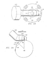
- FIGURE 1 is an isometric view of an eye 100 having a globe with the relevant exterior anatomical parts indicated as discussed above.
- FIGURE 2 shows a front elevational view of an eye 100 showing the scleral pockets 120 formed at approximately the forty five degree (45°) meridians of the eye, i.e., approximately halfway between the vertical and horizontal meridians of the globe. This location is preferred because it avoids interference with structures of the eye that are located generally on the vertical and horizontal meridians.
- FIGURE 2 shows the use of straight scleral pockets 120, Straight scleral pockets 120 are somewhat simpler to prepare surgically than curved scleral pockets (not shown), For many patients the use of straight scleral prostheses provide adequate treatment of presbyopia. Alternatively, curved scleral prostheses may be used as discussed in the "Presbyopia and Related Eye Disorder Patent Documents",
- FIGURE 3 shows a Cross-section of eye 100, taken along the line 3-3 in FIGURE 2 , showing the placement of scleral prosthesis 200 relative to the significant anatomical structures of the eye.
- FIGURE 3 shows the general configuration of the scleral pockets 120 and the prostheses 200 of the type illustrated in FIGURES 5-10 ,
- the anterior margins 122 of the scleral pockets 120 are located approximately in the plane 130 of the equator 110 of the lens 108.
- the presence of prosthesis 200 causes the portion of the sclera anterior to the scleral pocket 120 to be expanded somewhat more than the posterior portion. This places the sclera anterior to the scleral pocket 120 under a radial tension and causes it to expand from its normal diameter at that position.
- This scleral expansion draws with it the underlying ciliary body 116 and causes the ciliary body to be drawn away from the equator 110 of the lens 108. Accordingly, the expansion of the ciliary body 116 operates to increase the working distance of the ciliary muscle and restore, at least in part, the ability of the eye to accommodate for clear focusing on objects at different distances.
- FIGURE 4 shows an enlarged portion of one of the scleral pockets 120 with adjacent anatomical structures, It shows the relation of the scleral pocket 120 to the underlying structures and its location just posterior to the equator of the lens 108 and overlying the ciliary body 116.
- the surgical procedures described above to make incisions within the sclera 102 of eye 100 are done by hand. That is, the surgeon makes the incisions in sclera 102 that are required to form scleral pocket 120 using standard surgical tools such as a scalpel. The surgeon must be very skilled in the use of a scalpel to make incisions that have the required precision.
- system and method of the present invention provide a much more efficient and precise way to determine the optimum location for the required incisions.
- the system and method of the present invention is designed for use with a surgical tool that is specifically designed to make very precise incisions in the sclera 102 of an eye 100 to form a scleral pocket 120.
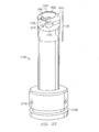
- FIGURE 11 shows a perspective view of a surgical tool 1100.
- surgical tool 1100 is capable of making incisions in eye 100 to create a scleral pocket 120 to receive a scleral prosthesis 200.
- Surgical tool 1100 comprises a base housing 1110 and a drive shaft housing 1120.
- Drive shaft housing 1120 comprises a blade mount housing 1130 that mounted on the drive shaft housing 1120 an angle to a central axis of drive shaft housing 1120.
- the reason for mounting blade mount housing 1130 at an angle with respect to the central axis of drive shaft housing 1120 is to facilitate the placement of blade mount housing 1130 on eye 100 during the surgical process.
- blade 1140 is mounted on blade mount housing 1130.
- FIGURE 12 shows surgical tool 1100 and a surgical tool controller 1200 for controlling the operation of surgical tool 1100.
- Surgical tool 1100 is coupled to surgical tool controller 1200 through control cable 1210.
- Control cable 1210 provides electrical power to surgical tool 1100 under the control of surgical tool controller 1200 to power the operation of blade 1140.
- Control cable 1210 also provides an "earth ground” to surgical tool 1100.
- Surgical tool controller 1200 receives external electrical power through power cord 1220.
- Foot switch 1230 is coupled to surgical tool controller 1200 through signal line 1240.
- the surgeon When the surgeon is ready to rotate blade 1140 to make an incision in eye 100 the surgeon steps on foot switch 1230. Foot switch 1230 then sends a control signal to surgical tool controller 1200 through signal line 1240.
- surgical tool controller 1220 activates electrical power to surgical tool 1100 to cause blade 1140 to rotate in a forward direction and make the desired incision in eye 100.
- the time required for blade 1140 to make an incision in eye 100 is approximately two (2) seconds.
- the incision is complete, after blade 1140 has reached the end of its rotation in the forward direction.
- Surgical tool controller 1200 then automatically causes blade 1140 to rotate back out of the incision.
- Surgical tool 1100 is then ready to make another incision.
- foot switch 1230 immediately sends a control signal to surgical tool controller 1200 through signal line 1240.
- surgical tool controller 1220 causes the forward motion of blade 1140 to cease and then automatically rotates blade 1140 out of the incision.
- Surgical tool controller 1200 comprises a switch 1250 (on/off switch 1250) for activating the operation of surgical tool controller 1200.
- Surgical tool controller 1200 also comprises indicator lights 1260 that indicate the operational status of surgical tool controller 1200.
- FIGURE 13 shows an end view of base housing 1110 of surgical tool 1100.
- Base housing 1110 comprises a control cable receptacle 1300 capable of receiving control cable 1210 to electrically power surgical tool 1100.
- control cable receptacle 1300 is capable of receiving four (4) individual power plugs of control cable 1210.
- FIGURE 14 shows a cross section of base housing 1110.
- Base housing 1110 comprises control cable receptacle 1300, four power lines (collectively designated 1410), drive motor 1420, gearbox 1430, and a drive shaft 1440.
- control cable 1210 When control cable 1210 is placed into control cable receptacle 1300, four power plugs of control cable 1210 make contact with the four power lines 1410.
- two of the four power lines (line 1 and line 2) are coupled to a first winding circuit (circuit A) of motor 1420.
- the other two of the four power lines (line 3 and line 4) are coupled to a second winding circuit (circuit B) of motor 1420.
- motor 1420 When surgical tool controller 1200 powers up line 1 and line 2, then motor 1420 rotates in one direction (e.g., counterclockwise). When surgical tool controller 1200 powers up line 3 and line 4, then motor 1420 rotates in the other direction (e.g., clockwise). In this manner, motor 1420 provides both rotational motion to rotate blade 1140 forward to make an incision in eye 100 and provides rotational motion to rotate blade 1140 backwards to remove blade 1140 from the incision made in eye 100.
- the two types of rotational motion will be collectively referred to as "bidirectional rotational motion.”
- gearbox 1430 reduces the rotational speed provided by motor 1420 by a factor of sixty six (66:1). That is, the rotational speed output by gearbox 1430 is one sixty sixth (1/66) of the rotational speed provided to gearbox 1430 by motor 1420. This amount of rotational speed reduction is necessary to increase the torque and because the rotational speed provided by motor 1420 is too great to be used to rotate blade 1140 directly.
- the rotational output from gearbox 1430 is coupled to drive shaft 1440 of base housing 1110.
- FIGURE 16 shows a cross sectional view of drive shaft housing 1120 mounted within base housing 1110 and a cross sectional view of blade mount housing 1130. Blade 1140 is not shown in FIGURE 16 .
- Drive shaft housing 1120 seats within a receptacle of base housing 1110 and is held in place by conventional means such as a screw 1610.
- O-ring 1620 seals the juncture between the receptacle of base housing 1110 and drive shaft housing 1120.
- Drive shaft housing 1120 comprises drive shaft 1630.
- Drive shaft 1630 is supported within drive shaft housing 1120 by conventional bearings. As shown in FIGURE 16 , drive shaft 1630 is coupled to drive shaft 1440 of base housing 1110. The coupling of drive shaft 1630 and drive shaft 1440 is supported by conventional bearings. Drive shaft 1440 rotates drive shaft 1630.
- Blade mount housing 1130 comprises drive shaft 1640.
- Drive shaft 1640 is supported within blade mount housing 1130 by conventional bearings. As shown in FIGURE 16 , drive shaft 1640 is coupled to drive shaft 1630 of drive shaft housing 1120 at an angle. As shown in greater detail in FIGURE 17 , a beveled gear 1710 of drive shaft 1630 engages a beveled gear 1720 of drive shaft 1640. As drive shaft 1630 is rotated, the rotational motion of beveled gear 1720 of drive shaft 1630 is imparted to beveled gear 1720 of drive shaft 1640. The rotational motion of drive shaft 1640 is used to rotate blade 1140 (not shown in FIGURES 16 and 17 ) mounted on blade mount housing 1130.
- Base plate 1730 seats within an end of blade mount housing 1130 and is held in place by conventional means such as a screw 1740.
- Drive shaft 1640 extends through an aperture in base plate1730 so that base plate 1730 also provides support for drive shaft 1640.
- Conventional means such as a screw 1750 may be used to secure blade 1140 to drive shaft 1640.
- Screw 1750 may also serve as an extension 1750 of drive shaft 1640 onto which blade 1140 may be mounted.
- Base plate 1730 comprises portions forming a blade guide 1760 for guiding the rotation of blade 1140 and for stopping the rotation of blade 1140 after blade 1140 has been rotated by a desired amount.
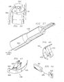
- FIGURE 18 shows a top plan view of blade 1140.
- FIGURE 19 shows a side view of blade 1140.
- FIGURE 20 shows a perspective view of blade 1140.
- Blade 1140 comprises support arm 1810 adapted to be mounted on an end of drive shaft 1640 of blade mount housing 1130.
- Blade 1140 also comprises a curved cutting blade 1820 for making an incision in the sclera 102 of eye 100.
- (1) support arm 1810 and curved cutting blade 1820 are formed as a unitary structure, and (2) curved cutting blade 1820 is circularly curved, and (3) curved cutting blade 1820 has end portions defining a tapered cutting point 1830.
- Scleral pocket 120 should be approximately four millimeters (4.0 mm) long, one and one half millimeters (1.5 mm) wide, and four hundred microns (400 ⁇ m) deep. Four hundred microns (400 ⁇ m) is equivalent to four tenths of a millimeter (0.4 mm).
- FIGURE 21 shows an external side view of drive shaft housing 1120 and blade mount housing 1130 and blade 1140.
- Aperture 2110 is provided to receive screw 1610 to fasten drive shaft housing 1120 within base housing 1110.
- Groove 2120 is provided to receive O-ring 1620 to seal the juncture between the receptacle of base housing 1110 and drive shaft housing 1120.
- Aperture 2130 is provided to receive screw 1740 to fasten base plate 1730 within blade mount housing 1130.
- An external reference line 2140 is marked on the surface of blade mount housing 1130.
- Line 2140 is located five and one half millimeters (5.5 mm) from the end of blade mount housing 1130.
- Line 2140 allows the surgeon to properly align blade 1140 during the surgical process. The surgeon aligns line 2140 with the limbus 106 of eye 100. This alignment properly positions blade 1140 to make an incision at the desired location on sclera 102 of eye 100.
- FIGURE 22 shows a perspective view of drive shaft housing 1120 and an end view of blade mount housing 1130.
- Base plate 1730 forms the end of blade mount housing 1130.
- the components of blade 1140 are shown separately as support arm 1810 and curved cutting blade 1820.
- Support arm 1810 is mounted on drive shaft 1640 by snapping an end of support arm 1810 onto an extension 1750 of drive shaft 1640.
- support arm 1810 may be mounted on drive shaft 1640 using conventional means such as a screw.
- Support arm 1810 is shown rotated forward to a position where it has abutted an edge of blade guide 1760. In this position curved cutting blade 1820 has completed its rotation and would have completed an incision if it has been adjacent to eye 100. Blade guide 1760 also guides the rotation of blade 1140. Blade guide 1760 is formed having a circularly shaped surface 2220 that is concentric with curved cutting blade 1820. The length of support arm 1810 supports curved cutting blade 1820 at a distance that is approximately four hundred microns (400 ⁇ m) away from the circularly shaped surface 2220 of blade guide 1760.
- the surgeon places the circularly shaped surface 2220 of blade guide 1760 on the sclera 102 of eye 100.
- the surgeon then begins the rotation of blade 1140 by stepping on foot switch 1230.
- blade 1140 continues to advance in a forward direction as support arm 1810 of blade 1140 rotates curved cutting blade 1820.
- Curved cutting blade 1820 then passes through sclera 102 of eye 100 at a depth of approximately four hundred microns (400 ⁇ m) to make the desired incision.
- the surgeon removes his or her foot from foot switch 1230 if the surgeon determines that it is desirable to stop the rotation of blade 1140.
- Surgical tool controller 1200 will immediately stop the rotation of blade 1140 and will then automatically rotate blade 1140 out of the incision.
- blade 1140 support arm 1810 and curved cutting blade 1820
- the components of blade 1140 may also be rotated back to abut the safety stop 2210.
- Blade guide 1760 and safety stop 2210 limit the rotational range of blade 1140 to only the rotation needed to perform the desired incisions.
- FIGURE 23 shows a top view illustrating how surgical tool 1100 is to be positioned over eye 100 to make incisions in the sclera 102 of eye 100.
- Eye 100 comprises sclera 102, iris 112, pupil 114, and limbus 106 (the boundary between sclera 102 and iris 112).
- Iris 114 and portions of limbus 106 are shown in dotted outline in FIGURE 23 because they are obscured by drive shaft housing 1120 and blade mount housing 1130.
- the surgeon aligns line 2140 on blade mount housing 1130 with the limbus 106 of eye 100. This alignment properly positions blade 1140 to make an incision at the desired location on sclera 102 of eye 100.
- FIGURE 24 shows a side view illustrating how surgical tool 1100 is to be positioned over eye 100 to make incisions in the sclera 102 of eye 100.
- the surgeon aligns line 2140 on blade mount housing 1130 with limbus 106 of eye 100. As described with reference to FIGURE 23 this alignment properly positions blade 1140.
- the reason for mounting blade mount housing 1130 at an angle with respect to the central axis of drive shaft housing 1120 is now apparent. It is to facilitate the placement of blade mount housing 1130 on eye 100 during the surgical process.
- FIGURE 25 shows a perspective view of an alternate advantageous embodiment 2500 of blade guide 1760.
- Blade guide 2500 is mounted on base plate 1730.
- blade guide 2500 comprises an end portion 2510 forming a first blade slot 2520 on a first end of blade guide 2500.
- Blade guide 2500 also comprises an end portion 2530 forming a second blade slot 2540 on a second end of blade guide 2500.
- Blade guide 2500 operates in the same manners as blade guide 1760 except that the end portions, 2510 and 2530, of blade guide 2500 provide additional external protection for curved cutting blade 1820 of blade 1140.
- End portions, 2510 and 2530 may also be seated against sclera 102 of eye during the surgical process to provide additional peripheral contact between blade guide 2500 and sclera 102 and to ensure a proper length for an incision.
- FIGURE 26 shows an end view of blade guide 2500.
- Blade guide 2500 is formed having a circularly shaped surface 2550 that is concentric with curved cutting blade 1820.
- the length of support arm 1810 supports curved cutting blade 1820 at a distance that is approximately four hundred microns (400 ⁇ m) away from the circularly shaped surface 2550 of blade guide 2500.
- a pressure sensor 2560 within blade guide 2500 senses the pressure of the sclera 102 against the circularly shaped surface 2550 of blade guide 2500.
- a pressure sensor control line (not shown) connects pressure sensor 2560 to surgical tool controller 1200.
- Pressure sensor 2560 senses whether there is sufficient pressure between the surface of sclera 102 and the circularly shaped surface 2550 of blade guide 2500. If there is not sufficient pressure then any incision made by blade 1140 would be too shallow. If pressure sensor 2560 does not detect sufficient pressure then surgical tool controller 1200 will not allow blade 1140 of surgical tool 1100 to rotate. If pressure sensor 2560 does detect sufficient pressure then surgical tool controller 1200 will allow blade 1140 of surgical tool 1100 to rotate.
- the surgeon begins the rotation of blade 1140 by stepping on foot switch 1230. As long as the surgeon is stepping on foot switch 1230 blade 1140 continues to advance in a forward direction as support arm 1810 of blade 1140 rotates curved cutting blade 1820. Curved cutting blade 1820 then passes through sclera 102 of eye 100 at a depth of approximately four hundred microns (400 ⁇ m) to make the desired incision. The surgeon removes his or her foot from foot switch 1230 if the surgeon determines that it is desirable to stop the rotation of blade 1140. Surgical tool controller 1200 will immediately stop the rotation of blade 1140 and will then automatically rotate blade 1140 out of the incision.
- FIGURE 27 shows an end view of blade guide 2500 showing how curved cutting blade 1820 passes through first blade slot 2520 of blade guide 2500, and through sclera 102 of eye 100, and through second blade slot 2540 of blade guide 2500 when support arm 1810 of blade 1140 is rotated.
- Curve 2710 represents the surface contour of sclera 102 of eye 100 before blade guide 2500 is placed in contact with eye 100.
- Curve 2720 represents the surface contour of eye 100 after blade guide 2500 is placed in contact with sclera 102 of eye 100. Pressure applied to keep blade guide 2500 in contact with sclera 102 of eye 100 temporarily makes the surface contour of the sclera 102 of eye 100 concave during the incision process.
- FIGURE 28 shows a side view of an end portion of blade mount housing 1130 showing the surface 2550 of blade guide 2500 that is placed in contact with sclera 102 of eye 100.
- Pressure sensor 2560 in blade guide 2500 is shown in dotted outline.
- curved cutting blade 1820 of blade 1140 is retracted.
- First blade slot 2520 and second blade slot 2540 of blade guide 2500 are visible.
- FIGURE 29 also shows a side view of an end portion of blade mount housing 1130 showing the surface 2550 of blade guide 2500 that is placed in contact with sclera 102 of eye 100.
- pressure sensor 2560 in blade guide 2500 is shown in dotted outline.
- curved cutting blade 1820 of blade 1140 has begun to be rotated through first blade slot 2520.
- Curved cutting blade 1820 is the process of rotating across surface 2550 of blade guide 2500 and is proceeding toward second blade slot 2540 of blade guide 2500.
- FIGURE 29 shows how curved cutting blade 1820 moves through blade guide 2500 during the process of making incisions in sclera 102 of eye 100.
- a scleral tissue fixation tool 3000 is utilized to restrain the movement of surgical tool 1100.
- scleral tissue fixation tool 3000 generally comprises a shaft 3010 having a fixation end 3020 that is capable of engaging and holding a portion of the surface of sclera 102.
- Scleral tissue fixation tool 3000 applies a force opposite to the tangent force generated by the curved cutting blade 1820 coming in contact with the sclera 102.
- the shaft 3010 is manually held and operated by the surgeon during the process of making an incision so that surgical tool 1100 does not move.
- scleral tissue fixation tool 3000 is approximately fifteen centimeters (15.0 cm) to twenty centimeters (20.0 cm) long and approximately one and one half millimeters (1.5 mm) wide.
- FIGURE 31 shows a perspective view of fixation end 3020 of scleral tissue fixation tool 3000.
- Fixation end 3020 comprises a first fixation barb 3110 formed on a first side of the end of shaft 3010.
- First fixation barb 3110 is formed by slicing and lifting up an end portion of shaft 3010.
- the amount of separation of first fixation barb 3110 from the end of shaft 3010 is in the range from three tenths of a millimeter (0.30 mm) to four tenths of a millimeter (0.40 mm).
- Fixation end 3020 also comprises a second fixation barb 3120 formed on a second side of the end of shaft 3010.
- Second fixation barb 3120 is formed by slicing and lifting up an end portion of shaft 3010. The amount of separation of second fixation barb 3120 from the end of shaft 3010 is the same as the amount of separation of first fixation barb 3110.
- First blade slot 2520 is where curved cutting blade 1820 first impacts sclera 102 and tends to cause translation of surgical tool 1100.
- the surgeon places the fixation end 3020 of the scleral tissue fixation tool 3000 onto the sclera 102 and twists shaft 3010 to the right to engage first fixation barb 3110 and second fixation barb 3120 into sclera 102.
- the surgeon holds the shaft 3010 against surgical tool 1100 during the incision process.
- the surgeon releases the scleral tissue fixation tool 3000 from sclera 102 by twisting shaft 3010 to the left to disengage the grip of fixation barbs, 3110 and 3120.
- the scleral tissue fixation tool 3000 shown in FIGURE 31 is a "right twist” tool. It engages by twisting shaft 3010 to the right and disengages by twisting shaft 3010 to the left.
- FIGURE 32 shows an alternative advantageous embodiment of scleral tissue fixation tool 3000.
- the scleral tissue fixation tool 3000 shown in FIGURE 32 is a "left twist" tool. It engages by twisting shaft 3010 to the left and disengages by twisting shaft 3010 to the right. Otherwise, the scleral tissue fixation tool 3000 shown in FIGURE 32 is identical to the scleral tissue fixation tool 3000 shown in FIGURE 31 . It comprises a first fixation barb 3210 and a second fixation barb 3220.
- the amount of separation 3230 of first fixation barb 3210 from the end of shaft 3010 is in the range from three tenths of a millimeter (0.30 mm) to four tenths of a millimeter (0.40 mm).
- the amount of separation of second fixation barb 3220 from the end of shaft 3010 is the same as the amount of separation of first fixation barb 3210.
- a special type of vacuum operated blade guide 3300 is utilized to restrain the movement of the sclera 102 and the translational movement of surgical tool 1100 generated from the impact of the curved cutting blade 1820.
- a vacuum is applied to seat blade guide 330 against sclera 102 during the process of making an incision.
- FIGURE 33 shows an end view of blade guide 3300.
- Blade guide 3300 is mounted on base plate 1730.
- blade guide 3300 comprises an end portion 3310 forming a first blade slot 3320 on a first end of blade guide 3300.
- Blade guide 3300 also comprises an end portion 3330 forming a second blade slot 3340 on a second end of blade guide 3300.
- the end portions, 3310 and 3330, of blade guide 3300 provide additional external protection for curved cutting blade 1820 of blade 1140.
- End portions, 3310 and 3330 are seated against sclera 102 of eye 100 during the surgical process to provide additional peripheral contact between blade guide 3300 and sclera 102 to ensure proper scleral pocket length.
- Blade guide 3300 is formed having a circularly shaped surface 3350 that is concentric with curved cutting blade 1820.
- the length of support arm 1810 supports curved cutting blade 1820 at a distance that is approximately four hundred microns (400 ⁇ m) away from the circularly shaped surface 3350 of blade guide 3300.
- a pressure sensor 3390 within blade guide 3300 senses the pressure of the sclera 102 against the circularly shaped surface 3350 of blade guide 3300.
- a pressure sensor control line (not shown) connects pressure sensor 3390 to surgical tool controller 1200.
- Pressure sensor 3390 senses whether there is sufficient pressure between the surface of sclera 102 and the circularly shaped surface 3350 of blade guide 3300. If there is not sufficient pressure then any incision made by blade 1140 would be too shallow. If pressure sensor 3390 does not detect sufficient pressure then surgical tool controller 1200 will not allow blade 1140 of surgical tool 1100 to rotate. If pressure sensor 3390 does detect sufficient pressure then surgical tool controller 1200 will allow blade 1140 of surgical tool 1100 to rotate.
- the surgeon begins the rotation of blade 1140 by stepping on foot switch 1230. As long as the surgeon is stepping on foot switch 1230 blade 1140 continues to advance in a forward direction as support arm 1810 of blade 1140 rotates curved cutting blade 1820. Curved cutting blade 1820 then passes through sclera 102 of eye 100 at a depth of approximately four hundred microns (400 ⁇ m) to make the desired incision. The surgeon removes his or her foot from foot switch 1230 if the surgeon determines that it is desirable to stop the rotation of blade 1140. Surgical tool controller 1200 will immediately stop the rotation of blade 1140 and will then automatically rotate blade 1140 out of the incision.
- Blade guide 3300 also comprises portions that form a vacuum chamber 3360 within the interior of blade guide 3300. Blade guide 3300 also comprises portions that form a plurality of access ports, 3365, 3370, and 3375, that extend from vacuum chamber 3360 through the circularly shaped surface 3350 of blade guide 3300 to apply vacuum to the surface of sclera 102. Blade guide 3300 also comprises a vacuum coupling 3380 capable of being connected to a vacuum supply line (not shown in FIGURE 33 ).
- FIGURE 34 shows a perspective view of blade guide 3300 showing end portion 3310 and first blade slot 3320.
- FIGURE 34 also shows end portion 3330 and second blade slot 3340.
- Vacuum coupling 3380 extends from the exterior of blade guide 3300 to vacuum chamber 3360 (not shown in FIGURE 34 ) located within blade guide 3300.
- FIGURE 35 shows an end view of blade guide 3300 showing the placement of circularly shaped surface 3350 of blade guide 3300 on the surface of sclera 102.
- end portion 3310, first blade slot 3320, end portion 3330 and second blade slot 3340 previously shown in FIGURE 34 have been omitted from FIGURE 35 .
- Vacuum coupling 3380 is coupled to a vacuum supply line 3500.
- Vacuum supply line 3500 provides a vacuum to vacuum chamber 3360.
- the vacuum causes air to pass through access ports 3365, 3370, and 3375 into vacuum chamber 3360 (shown by arrows in FIGURE 35 ) when access ports 3365, 3370, and 3375 are open to the atmosphere.
- the vacuum in vacuum chamber 3360 causes sclera 102 to adhere to the surface of circularly shaped surface 3350.
- the adhesion caused by the vacuum in vacuum chamber 3360 restrains the movement of sclera 102 when curved cutting blade 1820 is rotated into sclera 102 to make an incision.
- FIGURE 36 shows how vacuum supply line 3500 is connected to vacuum coupling 3380 of blade guide 3300.
- FIGURE 37 shows how vacuum supply line 3500 may be externally located along the length of surgical tool 1100.
- FIGURE 38 shows a flow chart of an advantageous embodiment of a method for making incisions to form a scleral pocket 120 for a scleral prosthesis 200.
- the steps of the method are generally denoted with reference numeral 3800.
- Blade mount housing 1130 of surgical tool 1100 is positioned over sclera 102 of eye 100 by aligning external reference line 2140 of blade mount housing 1130 with limbus 106 of eye 100 (step 3810). Then blade mount housing 1130 and blade 1140 are placed into contact with sclera 102 (step 3820).
- sclera 102 and surgical tool 1100 are then restrained by engaging and holding sclera 102 with scleral tissue fixation tool 3000 (step 3830).
- Surgical tool 1100 rotates curved cutting blade 1820 through sclera 102 to make an incision to form scleral pocket 120 (step 3840).
- surgical tool 110 rotates curved cutting blade 1820 back out of the incision made through sclera 102 (step 3850).
- sclera 102 is released by disengaging scleral tissue fixation tool 3000 (steep 3860).
- the incision forms scleral pocket 120 to receive scleral prosthesis 200.
- FIGURE 39 shows a flow chart of an alternate advantageous embodiment of a method for making incisions to form a scleral pocket 120 for a scleral prosthesis 200.
- the steps of the method are generally denoted with reference numeral 3900.
- Blade mount housing 1130 of surgical tool 1100 is positioned over sclera 102 of eye 100 by aligning external reference line 2140 of blade mount housing 1130 with limbus 106 of eye 100 (step 3910). Then blade mount housing 1130 and blade 1140 are placed into contact with sclera 102 (step 3920).
- sclera 102 and surgical tool 1100 are then restrained by engaging and holding sclera 102 with a vacuum from vacuum chamber 3360 of blade guide 33000 (step 3930).
- Surgical tool 1100 rotates curved cutting blade 1820 through sclera 102 to make an incision to form scleral pocket 120 (step 3940).
- surgical tool 110 rotates curved cutting blade 1820 back out of the incision made through sclera 102 (step 3950).
- sclera 102 is released by venting the vacuum in vacuum chamber 3360 of blade guide 3300 (step 3960).
- the incision forms scleral pocket 120 to receive scleral prosthesis 200.
- FIGURE 40 shows a first perspective view of an alternate advantageous embodiment of blade 1140 of surgical tool 1100 of the present invention comprising support arm 4010 and curved cutting blade 4020.
- support arm 1810 and curved cutting blade 1820 are formed as a unitary structure.
- curved cutting blade 4020 is detachable from support arm 4010.
- FIGURE 41 shows a second perspective view of the alternate advantageous embodiment of blade 1140 shown in FIGURE 40 .
- Curved cutting blade 4020 comprises an extension 4030 having portions that form an aperture 4040 through extension 4030.
- a string-like connector 4200 e.g., a plastic fiber 4200
- Surgical tool 1100 rotates support arm 4010 and causes curved cutting blade 4020 to pass through sclera 102 as previously described.
- curved cutting blade 4020 is disconnected from support arm 4010 after the incision in sclera 102 has been made. Curved cutting blade 4020 remains within the incision. Surgical tool 1100 is removed. Then the leading edge of curved cutting blade 4020 is withdrawn from the incision in the forward direction. Because curved cutting blade 4020 is tied to scleral prosthesis 200 by string-like connector 4200 the withdrawal of curved cutting blade 4020 from the incision pulls scleral prosthesis 200 into the incision. Curved cutting blade 4020 acts as a needle pulling the string-like connector 4200. Curved cutting blade 4020 is then re-attached to support arm 4010 for use in making the next incision of sclera 102.
- FIGURE 43 shows a first perspective view of a second alternate advantageous embodiment of blade 1140 of surgical tool 1100 of the present invention comprising support arm 4310 and curved cutting blade 4320.
- support arm 1810 and curved cutting blade 1820 are formed as a unitary structure.
- curved cutting blade 4320 is detachable from support arm 4310.
- a central portion 4330 of curved cutting blade 4320 is detachable from the other portions of curved cutting blade 4320.
- Curved cutting blade 4320 comprises three portions. The three portions are (1) detachable central portion 4330, and (2) detachable tip 4340, and (3) blade portion 4350.
- FIGURE 44 shows a second perspective view of the second alternate advantageous embodiment of blade 1140 shown in FIGURE 43 . Central portion 4330 is shown shaded in FIGURES 43 and 44 .
- Curved cutting blade 4320 is rotated into sclera 102 to form an incision in the manner previously described.
- the curved cutting blade 4320 is detached from support arm 4310 while curved cutting blade 4320 remains within the incision.
- FIGURE 45 shows a side view of the three portions (4330, 4340, 4350) of curved cutting blade 4320 within an incision.
- detachable tip 4340 is detached from detachable central portion 4330 (e.g., by forceps) and is removed from the incision.
- blade portion 4350 is detached from detachable central portion 4330 and is removed from the incision.
- Detachable central portion 4330 is left within the incision to serve as a scleral prosthesis 200.
- FIGURE 46 shows a first perspective view of a third alternate advantageous embodiment of blade 1140 of surgical tool 1100 comprising support arm 4610 and curved cutting blade 4620.
- support arm 1810 and curved cutting blade 1820 are formed as a unitary structure.
- curved cutting blade 4620 is detachable from support arm 4610.
- curved cutting blade 4620 has portions that define a conduit 4630 through curved cutting blade 4620.
- Slidably disposed within conduit 4630 is scleral prosthesis 200.
- Plunger 4640 is also slidably disposed within conduit 4630.
- Plunger 4630 abuts scleral prosthesis 200.
- FIGURE 47 shows a second perspective view of the third alternate advantageous embodiment of blade 1140 shown in FIGURE 46 . Scleral prosthesis 200 is shown shaded in FIGURES 46 and 47 .
- Curved cutting blade 4620 is rotated into sclera 102 to form an incision in the manner previously described.
- the curved cutting blade 4620 is detached from support arm 4610 while curved cutting blade 4620 remains within the incision.
- FIGURE 48 shows a cross sectional side view of curved cutting blade 4620.
- Curved cutting blade 4620 is withdrawn from the incision.
- Plunger 4640 remains in place against scleral prosthesis 200 as curved cutting blade 4620 is withdrawn from the incision.
- Plunger 4640 prevents scleral prosthesis 200 from being withdrawn from the incision.
- Plunger 4640 finally pushes scleral prosthesis 200 out of conduit 4630 and into the incision. Then plunger 4640 is withdrawn from the incision leaving scleral prosthesis 200 properly placed within the incision.
- scleral prosthesis 200 is capable of being filled with a fluid. Scleral prosthesis 200 is filled with a fluid after scleral prosthesis 200 has been placed within the incision in order to increase the size of scleral prosthesis 200.
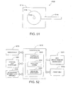
- FIGURE 49 illustrates a schematic representation of the geometry of the structure of eye 100.
- FIGURE 50 illustrates a schematic representation of distances between certain structures of eye 100. The system and method of the present invention for determining a position for scleral pocket 120 in the sclera 102 of eye 100 will be described with reference to the geometry of the structures of eye 100 shown in FIGURE 49 and in FIGURE 50 .
- a cross section of eye 100 is represented by two intersecting circles 4910 and 4920.
- Circle 4910 represents the curvature of the cornea 104 of eye 100.
- the cornea 104 of eye 100 is slightly flatter at its periphery that at its center, the cornea 104 will be assumed to be spherical. This assumption does not significantly affect the accuracy of the calculations for determining the position for scleral pocket 120.
- the radius of circle 4910 is designated with the letter C.
- Circle 4920 represents the curvature of the sclera 102 of eye 100.
- the radius of circle 4920 is designated with the letter D.
- the center of circle 4920 represents the center of a scleral shell 102 that represents the sclera 102 of eye 100.
- the circumference of circle 4910 and the circumference of circle 4920 intersect at point 4930 and point 4940. It is understood that FIGURE 1 represents a cross section of eye 100 and that point 4930 and point 4940 are only two of the points on the corneal diameter of eye 100.
- the plane 4950 that is perpendicular to the axis of eye 100 and that passes through point 4930 and point 4940 on the corneal diameter is referred to as the corneal plane 4950.
- the diameter of the cornea 104 is designated with the letter A.
- the distance from the anterior central corneal surface to the corneal plane 4950 is designated with the letter E.
- the distance from the corneal plane 4950 to the center of circle 4920 i.e., the center of the scleral shell 102) is designated with the letter F.
- the axial length of eye 100 is designated with the letter B. As shown in FIGURE 1 , the axial length B is equal to the sum of the distances D, F and E.
- the method of the present invention first determines the value of radius D of circle 4920 from values that can be empirically measured.
- the values of the corneal diameter A, the mean radius of curvature C of the cornea, and the axial length B of the eye 100 can be measured.
- an ultrasound biomicroscope may suitably be used to determine a value for the corneal diameter A.
- Mean central keratometry may be used to determine a value for the mean radius of curvature C of the cornea.
- An ultrasound biomicroscope or an A-scan may be used to determine a value of the axial length B of eye 100.
- alternate approaches may be used in lieu of any of the same.
- a measured value of corneal diameter A may be twelve millimeters (12.00 mm).
- a measured value for the radius of curvature C of the cornea may be eight millimeters (8.00 mm).
- a measured value for the axial length B may be twenty-two and three tenths millimeters (22.3 mm).
- a value of the radius D of the scleral shell may be calculated from these values.
- the axial length B is equal to the sum of the distances D, F and E.
- the value of D can then be determined by using the fact that the axial length B is equal to the sum of the distances D, F and E.
- B D + D 2 - A / 2 2 1 2 + C - C 2 - A / 2 2 1 2 Inserting the measured values for A, B and C into Equation (3) and solving for D gives a value for D of ten and seven tenths millimeters (10.7 mm).
- the distance from the anterior central corneal surface to the anterior surface of the lens 108 is three and seven tenths millimeters (3.7 mm). This distance is designated with the letter G. It is also known from empirical measurements that the distance from the anterior central corneal surface to the posterior surface of the lens 108 is seven and seven tenths millimeters (7.7 mm). The thickness of the lens 108 is the difference of these two distances. The thickness of the lens 108 is given by 7.7 mm minus 3.7 mm. The thickness of the lens 108 is four millimeters (4.0 mm). The thickness of the lens 108 is designated with the letter J. Symbolically, the thickness J of lens 108 equals H - G.
- the position of the lens equatorial plane 130 (with respect to the anterior surface of the lens 108) can be determined by multiplying the thickness of the lens 108 by an empirical percentage that has been previously determined from measurements made on the relative position of the lens equator of cadaver eyes. Assume that the present measurement is being made for an eye 100 of a fifty year old person. From empirical measurements the appropriate percentage is forty percent (40%). The position of the lens equatorial plane 130 is forty percent (40%) of four millimeters (4.0 mm) (i.e., one and six tenths millimeters (1.6 mm)) from the anterior surface of the lens 108.
- the distance from the anterior central corneal surface to the lens equatorial plane 130 is given by the sum of the distance G and the distance 1.6 mm. As previously noted, the value of G is 3.7 mm. Therefore, the distance from the anterior central corneal surface to the lens equatorial plane 130 is five and three tenths millimeters (5.3 mm).
- Equation (1) the distance E from the anterior central corneal surface to the corneal plane 4950 is given by Equation (1). Inserting the measured values for A and C into Equation (1) and solving for E gives a value for E of two and seven tenths millimeters (2.7 mm).
- the distance between the corneal plane 4950 and the lens equatorial plane 130 is designated by the letter L.
- the distance L may be obtained by subtracting the distance from the anterior central corneal surface to the corneal plane 4950 (i.e., the distance E) from the distance from the anterior central corneal surface to the lens equatorial plane 130.
- the distance L equals 5.3 mm minus 2.7 mm. That is, the distance L equals two and six tenths millimeters (2.6 mm).
- Equation (2) the distance F from the center of the scleral shell 102 to the corneal plane 4950 is given by Equation (2). Inserting the measured value for A and the calculated value for D into Equation (2) and solving for F gives a value for F of eight and eighty six hundredths millimeters (8.86 mm).
- the distance from the center of the scleral shell 102 to the lens equatorial plane 130 is designated by the letter K.
- the distance K may be obtained by subtracting the distance between the corneal plane 4950 and the lens equatorial plane 130 (i.e., the distance L) from the distance from the center of the scleral shell 102 to the corneal plane 4950.
- the distance K equals 8.86 mm minus 2.6 mm. That is, the distance K equals six and twenty six hundredths millimeters (6.26 mm).
- the distance from the axis of eye 100 to the point where the lens equatorial plane 130 crosses the sclera 102 is designated by the letter M.
- the front of the scleral pocket 120 should be placed four hundred fifty microns (450 ⁇ ) posterior to the lens equatorial plane 130. Four hundred fifty microns is equivalent to four hundred fifty thousandths of a millimeter (0.450 mm). The point of location for the front of the scleral pocket 120 is designated with the letter Q in FIGURE 50 .
- the distance from the center of the cornea 104 to the point of location for the front of the scleral pocket 120 is designated with the letter N.
- the distance N is equal to the sum of the distance M and four hundred fifty thousandths of a millimeter (0.450 mm).
- the distance N equals 8.67 mm plus 0.450 mm. That is, the distance N equals nine and twelve hundredths millimeters (9.12 mm).
- the radius of the scleral tissue fixation tool 3000 is seven hundred fifty microns (750 ⁇ ). Seven hundred fifty microns is equivalent to seven hundred fifty thousandths of a millimeter (0.750 mm). The distance from the base plate 1730 of the surgical tool hand piece to the anterior edge of the drive blade 1140 is seven hundred fifty microns (750 ⁇ ).
- the position to place the center of the scleral tissue fixation tool 3000 is designated with the letter P in FIGURE 50 .
- the distance P is the distance from the axis of eye 100 to the center of the scleral tissue fixation tool 3000.
- the distance P equals 9.12 mm minus 1.5 mm. That is, the distance P equals seven and sixty two hundredths millimeters (7.62 mm).
- an applanation marking plate may be used to mark the position of the center of the scleral tissue fixation tool 3000 on the sclera of eye 100.
- a micrometer is used to set the value of 7.62 mm on the applanation marking plate.
- FIGURE 51 illustrates an applanation marking plate assembly 5100.
- Applanation marking plate assembly 5100 comprises applanation marking plate 5110.
- Applanation marking plate 5110 is a transparent plate made of clear glass, plastic or other suitable material.
- applanation marking plate 5110 comprises a square having sides that are approximately sixteen millimeters (16 mm) in length.
- Applanation marking plate assembly 5100 further comprises a circular marking ring 5120 on applanation marking plate 5110.
- Marking ring 5120 has a circular shape with the center of the circle located in the center of applanation marking plate 5110.
- the size of marking ring 5120 is adjustable.
- Applanation marking plate assembly 5100 comprises a micrometer 5140 for adjusting the size of marking ring 5120.
- Applanation marking plate assembly 5100 further comprises an applanating circle 5130 on applanation marking plate 5110.
- the center of applanating circle 5130 is located in the center of applanation marking plate 5110.
- the size of applanating circle 5130 is fixed.
- the diameter of applanating circle 5130 is three millimeters (3.0 mm).
- the diameter of applanating circle 5130 may be greater than three millimeters (3.0 mm) or less than three millimeters (3.0 mm).
- Applanation marking plate assembly 5100 may be used to mark the position for placing the scleral tissue fixation tool 3000 on the sclera of eye 100. First the surgeon uses micrometer 5140 to adjust the size of marking ring 5120 so that the radius of marking ring 5120 is equal to seven and sixty two hundredths millimeters (7.62 mm). Then the surgeon places the applanation marking plate 5110 on the center of the cornea of eye 100.
- the surgeon may use a central fixation light source (not shown).
- the fixation light from the central fixation light source enters through one of the side ports of a surgical microscope (not shown).
- the fixation light then exits through an objective lens on the same side of the surgical microscope. Assume that the fixation light enters through the right side port and exits through the right objective lens of the surgical microscope.
- the patient fixates the fixation light that comes through the right objective lens of the surgical microscope while the surgeon looks through only the right eyepiece of the surgical microscope.
- the surgeon then aligns the center of applanating circle 5030 with the patient's corneal Purkinje image of the fixation light to determine the location of the center of the cornea 104 of the patient.
- the surgeon must make sure that the measurement is being made from the center of the cornea 104 and that the applanation is circular.
- the marks on the sclera 102 of eye 100 define the position for locating the center of the scleral tissue fixation tool 3000. This location marks an optimum position for placing scleral pocket 120 to receive scleral prosthesis 200.
- FIGURE 52 illustrates a controller 5210 that is capable of carrying out the method of the present invention.
- Controller 5210 is coupled to and receives eye measurements from eye measurement equipment 5220.
- Eye measurement equipment 5220 may comprise, for example, an ultrasound biomicroscope for determining a value for the corneal diameter A, a keratometer for determining a value for the mean radius of curvature C of the cornea, and an ultrasound biomicroscope for determining a value of the axial length B of eye 100.
- Controller 5210 is also coupled to an input unit 5230. Controller 5210 can receive input parameters and other information from the surgeon through input unit 5230, a memory, or other device or processor. For example, the surgeon can use input unit 5230 to inform controller 5210 of the age of the person whose eye is being measured.
- Controller 5210 comprises a software processor 5240 that is capable of executing computer instructions stored in a memory (not shown) within controller 5210.
- Software processor 5240 comprises an operating system 5250 and an eye model application 5260.
- Eye model application 5260 comprises computer software instructions for making the various calculations of the method of the present invention.
- Eye model application 5260 receives the values of the measured parameters of eye 100 that are measured by eye measurement equipment 5220. Eye model application 5260 uses the eye measurement values from eye measurement equipment 5220 and input from input unit 5230 to mathematically model the operation of eye 100 in accordance with the steps of the method of the present invention. Eye model application 5260 contains a database (not shown) that contains the empirically determined percentages (as a function of the age of eye 100) with which to multiply the thickness of lens 108 to determine the position of lens equatorial plane 130.
- Eye model application 5260 obtains information about eye 100 from the mathematical model of eye 100 that is created by eye model application 5260. In particular, eye model application 5260 calculates a precise location for a scleral pocket 120 on the sclera 102 of eye 100. Information from eye model application 5260 may be output by controller 5210 to a data display 5270 for the surgeon to review.
- Information from eye model application 5260 may also be supplied to surgical tool controller 1200 to assist the surgical tool controller in accurately positioning blade 1140 of surgical tool 1100.
- Surgical tool controller 1200 may use information from eye model application 5260 to automatically determine an incision point for the incision to create scleral pocket 120 while surgical tool 1100 is in place over the sclera 102 of eye 100.
- scleral prosthesis 200 is capable of being filled with a fluid.
- Surgical tool controller 1200 may use information from eye model application 5260 to select a size of scleral prosthesis 200 when scleral prosthesis 200 is filled with fluid after scleral prosthesis 200 has been placed within scleral pocket 120.
- Information from eye model application 5260 may also be supplied to applanation marking plate assembly 5100 to operate micrometer 5140 to accurately position marking ring 5120.
- FIGURE 53 illustrates a flow chart showing an advantageous embodiment of the method of the present invention.
- the 2 steps of the method are collectively referred to with reference numeral 5300.
- the values of the corneal diameter A, the corneal radius of curvature C, and the axial length B of eye 100 are measured (step 5310).
- the value of the radius D of the scleral shell 102 is then calculated from the measured values of A, B, and C. (step 5320).
- the thickness J of the lens is calculated and the position of the lens equatorial plane 130 is calculated (step 5330).
- the distance L between the corneal plane 4950 and the lens equatorial plane 130 is then calculated (step 5340).
- the distance K from the center of the scleral shell 102 to the lens equatorial plane 130 is then calculated (step 5350).
- the distance M from the axis of eye 100 to the point where the lens equatorial plane 130 crosses the sclera 102 is then calculated (step 5360).
- the distance N from the center of cornea 104 to the front of the scleral pocket 120 is then calculated (step 5370).
- the method of present invention precisely determines the optimum position for the location of scleral pocket 120.
Landscapes
- Health & Medical Sciences (AREA)
- Ophthalmology & Optometry (AREA)
- Life Sciences & Earth Sciences (AREA)
- Animal Behavior & Ethology (AREA)
- Engineering & Computer Science (AREA)
- Biomedical Technology (AREA)
- Heart & Thoracic Surgery (AREA)
- Vascular Medicine (AREA)
- Veterinary Medicine (AREA)
- Public Health (AREA)
- General Health & Medical Sciences (AREA)
- Surgery (AREA)
- Nuclear Medicine, Radiotherapy & Molecular Imaging (AREA)
- Cardiology (AREA)
- Oral & Maxillofacial Surgery (AREA)
- Transplantation (AREA)
- Prostheses (AREA)
Claims (20)
- Appareil permettant de localiser une position sur la sclère (102) d'un oeil (100) qui est appropriée pour former une poche sclérale (120) à l'intérieur du tissu scléral de l'oeil (100) pour recevoir une prothèse sclérale (200), ledit appareil étant destiné à être utilisé avec un outil chirurgical permettant de réaliser l'incision dans le tissu scléral d'un oeil et comprenant :un contrôleur (5210) servant à : (i) recevoir des mesures oculaires qui évaluent une taille de parties dudit oeil (100), ledit contrôleur (5210) comprenant un processeur de logiciel (5240) ; et (ii) utiliser lesdites mesures oculaires pour créer un modèle mathématique dudit oeil (100) ; et (iii) déterminer à partir dudit modèle mathématique dudit oeil (100) un emplacement sur ladite sclère (102) dudit oeil (100) qui est approprié pour réaliser une incision ayant la forme d'une poche sclérale (120) qui soit apte à recevoir ladite prothèse sclérale (200).
- Appareil selon la revendication 1, dans lequel ledit contrôleur (5210) est apte à déterminer à partir dudit modèle mathématique dudit oeil (100) un emplacement sur la sclère (102) dudit oeil (100) où une projection d'un plan équatorial de cristallin (130) dudit oeil (100) croise la sclère (102) dudit oeil (100).
- Appareil selon la revendication 1, dans lequel ledit contrôleur (5210) est apte à déterminer à partir dudit modèle mathématique dudit oeil (100) un rayon D d'une coque sclérale dudit oeil (100) à partir d'une valeur mesurée de diamètre cornéen A dudit oeil (100), d'une valeur mesurée de rayon de courbure C moyen dudit oeil (100) et d'une valeur mesurée d'une longueur axiale B dudit oeil (100).
- Appareil selon la revendication 2, dans lequel ledit contrôleur (5210) est apte à déterminer à partir dudit modèle mathématique dudit oeil (100) un emplacement dudit plan équatorial de cristallin (130) par rapport à la surface antérieure d'un cristallin dudit oeil (100).
- Appareil selon la revendication 4, dans lequel ledit contrôleur (5210) est apte à déterminer à partir dudit modèle mathématique dudit oeil (100) ledit emplacement dudit plan équatorial de cristallin (130) en multipliant une épaisseur dudit cristallin (108) par un pourcentage empirique stocké à l'intérieur dudit contrôleur (5210).
- Appareil selon la revendication 5, dans lequel ledit contrôleur (5210) est apte à déterminer à partir dudit modèle mathématique dudit oeil (100) une distance entre un plan cornéen (4950) dudit oeil (100) et ledit plan équatorial de cristallin (130) dudit oeil (100).
- Appareil selon la revendication 6, dans lequel ledit contrôleur (5210) est apte à déterminer à partir dudit modèle mathématique dudit oeil (100) une distance k d'un centre de ladite coque sclérale (102) dudit oeil (100) audit plan équatorial de cristallin (130).
- Appareil selon la revendication 7, dans lequel ledit contrôleur (5210) est apte à déterminer à partir dudit modèle mathématique dudit oeil (100) une distance M d'un axe dudit oeil (100) à un point sur ladite sclère (102) dudit oeil (100) où une projection dudit plan équatorial de cristallin (130) dudit oeil (100) croise la sclère (102) dudit oeil (100).
- Appareil selon la revendication 8, dans lequel ledit contrôleur (5210) est apte à déterminer à partir dudit modèle mathématique dudit oeil (100) une distance N du centre d'une cornée (104) dudit oeil (100) à une position Q où il est optimal de localiser une partie avant de ladite poche sclérale (120) sur ladite sclère (102) dudit oeil (100).
- Appareil selon la revendication 9, dans lequel ledit contrôleur (5210) est apte à déterminer à partir dudit modèle mathématique dudit oeil (100) une distance du centre de ladite cornée (104) dudit oeil (100) à une position P sur la sclère (102) dudit oeil (100) où il est optimal de placer un centre d'un outil de fixation de tissu scléral (3000) pour limiter le mouvement dudit outil chirurgical lorsque ledit outil chirurgical réalise une incision dans ladite sclère (102) dudit oeil (100) pour former ladite poche sclérale (120).
- Appareil selon la revendication 1, dans lequel ledit contrôleur (5210) est apte à recevoir des informations concernant ledit oeil (100) depuis une unité d'entrée (5230).
- Appareil selon la revendication 1, dans lequel ledit contrôleur (5210) est en outre apte à fournir des informations dérivées dudit modèle mathématique dudit oeil (100) à l'un : d'un affichage de données (5270), d'un contrôleur d'outil chirurgical (1200) et d'un ensemble de plaque de marquage d'aplanation (5100).
- Procédé permettant de localiser une position sur la sclère (102) d'un oeil (100) qui est appropriée pour former une poche sclérale (120) à l'intérieur d'un tissu scléral de l'oeil (100) destinée à recevoir une prothèse sclérale (200), ledit procédé comprenant les étapes consistant à :recevoir des mesures oculaires qui évaluent une taille de parties dudit oeil (100) à l'intérieur d'un contrôleur (5210) qui comprend un processeur de logiciel (5240) ;utiliser lesdites mesures oculaires à l'intérieur dudit contrôleur (5210) pour créer un modèle mathématique dudit oeil ; etdéterminer à partir dudit modèle mathématique dudit oeil (100) un emplacement sur ladite sclère (102) dudit oeil (100) qui est approprié pour réaliser une incision ayant la forme d'une poche sclérale (120) qui soit apte à recevoir ladite prothèse sclérale (200).
- Procédé selon la revendication 13, comprenant en outre l'étape consistant à :déterminer à partir dudit modèle mathématique dudit oeil (100) un emplacement sur la sclère (102) dudit oeil (100) où une projection d'un plan équatorial de cristallin (130) dudit oeil (100) croise la sclère (102) dudit oeil (100).
- Procédé selon la revendication 13 comprenant en outre l'étape consistant à :déterminer à partir dudit modèle mathématique dudit oeil (100) un rayon D d'une coque sclérale (102) dudit oeil (100) à partir d'une valeur mesurée de diamètre cornéen A dudit oeil (100), une valeur mesurée de rayon de courbure C moyen dudit oeil (100), et une valeur mesurée d'une longueur axiale B dudit oeil (100).
- Procédé selon la revendication 14 comprenant en outre les étapes consistant à :déterminer à partir dudit modèle mathématique dudit oeil (100) un emplacement dudit plan équatorial de cristallin (130) par rapport à la surface antérieure d'un cristallin dudit oeil (100) ; etdéterminer à partir dudit modèle mathématique dudit oeil (100) ledit emplacement dudit plan équatorial de cristallin (130) en multipliant une épaisseur dudit cristallin (108) par un pourcentage empirique stocké à l'intérieur dudit contrôleur (5210).
- Procédé selon la revendication 16 comprenant en outre les étapes consistant à :déterminer à partir dudit modèle mathématique dudit oeil (100) une distance entre un plan cornéen dudit oeil (100) et ledit plan équatorial de cristallin (130) dudit oeil (100) ; etdéterminer à partir dudit modèle mathématique dudit oeil (100) une distance k d'un centre de ladite coque sclérale (102) dudit oeil (100) audit plan équatorial de cristallin (130).
- Procédé selon la revendication 17 comprenant en outre les étapes consistant à :déterminer à partir dudit modèle mathématique dudit oeil (100) une distance M d'un axe dudit oeil (100) à un point sur ladite sclère (102) dudit oeil (100) où une projection dudit plan équatorial de cristallin (130) dudit oeil (100) croise la sclère (102) dudit oeil (100) ; etdéterminer à partir dudit modèle mathématique dudit oeil (100) une distance N du centre d'une cornée (104) dudit oeil (100) à une position Q où il est optimal de localiser une partie avant de ladite poche sclérale (120) sur ladite sclère (102) dudit oeil (100).
- Procédé selon la revendication 18 comprenant en outre l'étape consistant à :déterminer à partir dudit modèle mathématique dudit oeil (100) une distance du centre de ladite cornée (104) dudit oeil (100) à une position P sur la sclère (102) dudit oeil (100) où il est optimal de placer un centre d'un outil de fixation de tissu scléral (3000) pour limiter le mouvement dudit outil chirurgical lorsque ledit outil chirurgical réalise une incision dans ladite sclère (102) dudit oeil (100) pour former ladite poche sclérale (120).
- Procédé selon la revendication 13 comprenant en outre les étapes consistant à :recevoir dans ledit contrôleur (5210) depuis une unité d'entrée (5230) des informations concernant ledit oeil (100) ; etfournir des informations dérivées dudit modèle mathématique dudit oeil (100) à l'un : d'un affichage de données (5270), d'un contrôleur d'outil chirurgical (1200) et d'un ensemble de plaque de marquage d'aplanation (5100).
Applications Claiming Priority (3)
| Application Number | Priority Date | Filing Date | Title |
|---|---|---|---|
| US38185102P | 2002-05-20 | 2002-05-20 | |
| US381851P | 2002-05-20 | ||
| PCT/US2003/015896 WO2003099103A2 (fr) | 2002-05-20 | 2003-05-20 | Systeme et procede permettant de determiner la position d'une poche sclerale pour une prothese sclerale |
Publications (2)
| Publication Number | Publication Date |
|---|---|
| EP1581093A2 EP1581093A2 (fr) | 2005-10-05 |
| EP1581093B1 true EP1581093B1 (fr) | 2011-08-03 |
Family
ID=29584329
Family Applications (1)
| Application Number | Title | Priority Date | Filing Date |
|---|---|---|---|
| EP03731270A Expired - Lifetime EP1581093B1 (fr) | 2002-05-20 | 2003-05-20 | Systeme et procede permettant de determiner la position d'une poche sclerale pour une prothese sclerale |
Country Status (6)
| Country | Link |
|---|---|
| US (2) | US7909780B2 (fr) |
| EP (1) | EP1581093B1 (fr) |
| AT (1) | ATE518499T1 (fr) |
| AU (1) | AU2003241530A1 (fr) |
| ES (1) | ES2368711T3 (fr) |
| WO (1) | WO2003099103A2 (fr) |
Families Citing this family (23)
| Publication number | Priority date | Publication date | Assignee | Title |
|---|---|---|---|---|
| US6638239B1 (en) | 2000-04-14 | 2003-10-28 | Glaukos Corporation | Apparatus and method for treating glaucoma |
| US7867186B2 (en) | 2002-04-08 | 2011-01-11 | Glaukos Corporation | Devices and methods for treatment of ocular disorders |
| AU2002258754B2 (en) | 2001-04-07 | 2006-08-17 | Glaukos Corporation | Glaucoma stent and methods thereof for glaucoma treatment |
| US7331984B2 (en) | 2001-08-28 | 2008-02-19 | Glaukos Corporation | Glaucoma stent for treating glaucoma and methods of use |
| US7909780B2 (en) * | 2002-02-22 | 2011-03-22 | Refocus Ocular, Inc. | System and method for determining a position for a scleral pocket for a scleral prosthesis |
| BRPI0415059A (pt) * | 2003-10-06 | 2006-11-28 | Crs & Asociates Companhia Amer | método para aumentar a acomodação ocular, e, sistema para uso em aumentar a capacidade de acomodação de um indivìduo |
| US20060116759A1 (en) * | 2004-11-30 | 2006-06-01 | Thornton Spencer P | Method of treating presbyopia and other eye conditions |
| US20060287662A1 (en) * | 2005-05-26 | 2006-12-21 | Ntk Enterprises, Inc. | Device, system, and method for epithelium protection during cornea reshaping |
| US20070162116A1 (en) * | 2006-01-11 | 2007-07-12 | Georges Baikoff | Method for locating optimum presbyopia implant location |
| US9248047B2 (en) * | 2006-01-23 | 2016-02-02 | Ziemer Holding Ag | System for protecting tissue in the treatment of eyes |
| CA2976837C (fr) * | 2006-07-11 | 2020-12-15 | Refocus Group, Inc. | Prothese sclerale pour traiter la presbytie et d'autres troubles oculaires |
| CA2668954C (fr) | 2006-11-10 | 2020-09-08 | Glaukos Corporation | Derivation uveosclerale et procedes pour son implantation |
| US8603081B2 (en) | 2007-08-23 | 2013-12-10 | Ntk Enterprises, Inc. | System and method for defining and controlling LTK and other surgical eye procedures to produce little or no stromal collagen shrinkage |
| US8083759B2 (en) | 2007-11-02 | 2011-12-27 | Refocus Ocular, Inc. | Apparatuses and methods for forming incisions in ocular tissue |
| US8201942B2 (en) * | 2008-04-02 | 2012-06-19 | Refocus Group, Inc. | System and method for identifying a position to insert a scleral prosthesis into an eye |
| US9554940B2 (en) | 2012-03-26 | 2017-01-31 | Glaukos Corporation | System and method for delivering multiple ocular implants |
| US9592151B2 (en) | 2013-03-15 | 2017-03-14 | Glaukos Corporation | Systems and methods for delivering an ocular implant to the suprachoroidal space within an eye |
| KR102463172B1 (ko) * | 2016-01-08 | 2022-11-04 | 삼성전자주식회사 | 동공 거리 결정 방법 및 장치 |
| US11116625B2 (en) | 2017-09-28 | 2021-09-14 | Glaukos Corporation | Apparatus and method for controlling placement of intraocular implants |
| WO2019070385A2 (fr) | 2017-10-06 | 2019-04-11 | Glaukos Corporation | Systèmes et procédés de pose de multiples implants oculaires |
| USD846738S1 (en) | 2017-10-27 | 2019-04-23 | Glaukos Corporation | Implant delivery apparatus |
| US11571333B2 (en) | 2020-05-18 | 2023-02-07 | Refocus Group, Inc. | Apparatus and method for securing ocular tissue and providing surgical tool positioning points |
| CN116636925B (zh) * | 2023-05-29 | 2024-05-10 | 天津医科大学眼科医院 | 基于3d打印技术的眼球模型条带设计方法 |
Family Cites Families (59)
| Publication number | Priority date | Publication date | Assignee | Title |
|---|---|---|---|---|
| US3609864A (en) | 1969-08-27 | 1971-10-05 | Roy C Bassett | Surgical blade handle |
| US3922784A (en) | 1975-03-03 | 1975-12-02 | Diagravure Film Mfg Corp | Swivel knife for manual operation with blade holder offset skewably from handle |
| US4071029A (en) | 1976-05-21 | 1978-01-31 | Stryker Corporation | Angle handpiece |
| US4340059A (en) * | 1980-10-23 | 1982-07-20 | Marinoff Gerald P | Radial keratotomy device |
| US4688570A (en) | 1981-03-09 | 1987-08-25 | The Regents Of The University Of California | Ophthalmologic surgical instrument |
| US5188125A (en) * | 1982-01-04 | 1993-02-23 | Keravision, Inc. | Method for corneal curvature adjustment |
| US4452235A (en) | 1982-01-04 | 1984-06-05 | Reynolds Alvin E | Method for corneal curvature adjustment |
| US4601290A (en) * | 1983-10-11 | 1986-07-22 | Cabot Medical Corporation | Surgical instrument for cutting body tissue from a body area having a restricted space |
| US4753655A (en) | 1984-04-17 | 1988-06-28 | Hecht Sanford D | Treating vision |
| US4669466A (en) * | 1985-01-16 | 1987-06-02 | Lri L.P. | Method and apparatus for analysis and correction of abnormal refractive errors of the eye |
| US4649919A (en) | 1985-01-23 | 1987-03-17 | Precision Surgical Instruments, Inc. | Surgical instrument |
| US4665914A (en) * | 1985-12-27 | 1987-05-19 | Emanuel Tanne | Automatic corneal surgery system |
| US4672964A (en) | 1986-02-21 | 1987-06-16 | Dee Robert N | Scalpel with universally adjustable blade |
| US4710193A (en) * | 1986-08-18 | 1987-12-01 | David Volk | Accommodating intraocular lens and lens series and method of lens selection |
| US4923467A (en) * | 1988-03-02 | 1990-05-08 | Thompson Keith P | Apparatus and process for application and adjustable reprofiling of synthetic lenticules for vision correction |
| US4955882A (en) * | 1988-03-30 | 1990-09-11 | Hakky Said I | Laser resectoscope with mechanical and laser cutting means |
| US5006123A (en) * | 1988-04-05 | 1991-04-09 | Soll David B | Sclera and/or limbus marking device for use in intraocular surgery |
| US5215104A (en) | 1988-08-16 | 1993-06-01 | Steinert Roger F | Method for corneal modification |
| US4986807A (en) * | 1989-01-23 | 1991-01-22 | Interventional Technologies, Inc. | Atherectomy cutter with radially projecting blade |
| US5090955A (en) | 1990-07-12 | 1992-02-25 | University Of Miami | Gel injection adjustable keratoplasty |
| US5222959A (en) * | 1990-07-17 | 1993-06-29 | Anis Aziz Y | Removal of tissue |
| US5492528A (en) | 1990-07-17 | 1996-02-20 | Anis; Azis Y. | Removal of tissue |
| US5098438A (en) * | 1990-08-23 | 1992-03-24 | Siepser Steven B | Procedures for intraocular surgery |
| US5203865A (en) * | 1990-08-23 | 1993-04-20 | Siepser Steven B | Surgical knives for use in ophthalmic surgery |
| US6033437A (en) | 1991-09-30 | 2000-03-07 | Orbital Implant Technology | Pegs for orbital implants |
| SG93223A1 (en) | 1992-04-10 | 2002-12-17 | Keravision Inc | Corneal vacuum centering guide and dissector |
| US6565584B1 (en) | 1992-04-10 | 2003-05-20 | Addition Technology, Inc. | Device and method for inserting a biocompatible material into the corneal stroma |
| US5522829A (en) | 1992-04-16 | 1996-06-04 | Arthur D. Little Enterprises, Inc. | Surgical cutting instrument |
| DK0653926T3 (da) | 1992-08-07 | 1999-11-01 | Keravision Inc | Intrastromal cornealring |
| US5437678A (en) | 1992-11-30 | 1995-08-01 | Neomedix Corporation | Ophthalmic lens removal method and apparatus |
| US5342377A (en) | 1992-12-18 | 1994-08-30 | Lazerson Howard E | Rotating blade capsulotomy instrument and method of performing a capsulotomy |
| US5891131A (en) * | 1993-02-01 | 1999-04-06 | Arizona Board Of Regents | Method and apparatus for automated simulation and design of corneal refractive procedures |
| US5431671A (en) | 1993-05-28 | 1995-07-11 | Nallakrishnan; Ravi | Surgical knife with retractable and angularly adjustable blade |
| US5653724A (en) * | 1993-08-18 | 1997-08-05 | Imonti; Maurice M. | Angled phacoemulsifier tip |
| US5441510A (en) * | 1993-09-01 | 1995-08-15 | Technology Development Center | Bi-axial cutter apparatus for catheter |
| US5423841A (en) | 1994-03-15 | 1995-06-13 | Kornefeld; Michael S. | Intraocular knife |
| US5571106A (en) | 1995-05-17 | 1996-11-05 | International Business Machines Corporation | Surgical cutting instrument |
| US20040073303A1 (en) | 1995-06-07 | 2004-04-15 | Harry J. Macey | Radial intrastromal corneal insert and a method of insertion |
| DE19540439C2 (de) * | 1995-10-30 | 1999-04-22 | Schwind Gmbh & Co Kg Herbert | Vorrichtung zur Hornhautchirurgie |
| US5817115A (en) * | 1995-12-04 | 1998-10-06 | Chiron Vision Corporation | Apparatus for resecting corneal tissue |
| US6051009A (en) | 1996-02-07 | 2000-04-18 | Hellenkamp; Johann F. | Automatic surgical device for cutting a cornea and a cutting blade assembly and control assembly |
| US5624456A (en) | 1996-02-07 | 1997-04-29 | Hellenkamp; Johann F. | Automatic surgical device for cutting a cornea |
| US6171336B1 (en) * | 1996-03-26 | 2001-01-09 | Mark R. Sawusch | Method, implant, and apparatus for refractive keratoplasty |
| US6328747B1 (en) | 1996-05-09 | 2001-12-11 | Itos Innovative Technology In Ocular Surgery, Ltd. | Method and a system for performing cataract surgery |
| US5908433A (en) | 1996-05-10 | 1999-06-01 | Stryker Corporation | Carpal tunnel knife |
| US6231583B1 (en) * | 1997-07-09 | 2001-05-15 | Joseph Y. Lee | Corneal circular channel dissecting device |
| BR9806306A (pt) * | 1997-10-08 | 2001-09-18 | Ras Holding Corp | Faixa escleral segmentada para tratamento de presbiopia e outros distúrbios de olho |
| US6007578A (en) * | 1997-10-08 | 1999-12-28 | Ras Holding Corp | Scleral prosthesis for treatment of presbyopia and other eye disorders |
| US6610075B1 (en) | 1997-10-24 | 2003-08-26 | Becton, Dickenson And Company | Keratome with suspended stabilized blade, improved suction ring with applanator and guided engagement with keratome cutter head, automated translation of the cutter head, and blade insertion tool |
| US6231582B1 (en) | 1997-12-18 | 2001-05-15 | Keravision, Inc. | Corneal pocketing tool |
| US20020055753A1 (en) | 1997-12-18 | 2002-05-09 | Thomas A. Silvestrini | Corneal implant methods and pliable implant therefor |
| US6264668B1 (en) | 1998-09-16 | 2001-07-24 | Arnold S. Prywes | Ophthalmologic instrument for producing a fistula in the sclera |
| US6918930B2 (en) | 1999-05-14 | 2005-07-19 | Valdemar Portney | Iris fixated intraocular lens suitable for use with attaching instrument |
| EA200200006A1 (ru) | 1999-06-07 | 2002-06-27 | Роналд А. Скачар | Склеральный протез для лечения пресбиопии и других расстройств зрения |
| US6358262B1 (en) | 1999-11-05 | 2002-03-19 | Alcon Universal Ltd. | Lamellar dissecting instrument |
| JP4080874B2 (ja) | 2000-12-20 | 2008-04-23 | フォックス ハロウ テクノロジーズ,インコーポレイティド | 減嵩カテーテル |
| US6692524B2 (en) * | 2001-01-19 | 2004-02-17 | Georges Baikoff | Techniques and implants for correcting presbyopia |
| WO2002067830A2 (fr) * | 2001-02-23 | 2002-09-06 | Ras Holding Corp | Systeme et procede permettant de faire des incisions pour des implants ophtalmiques scleraux |
| US7909780B2 (en) * | 2002-02-22 | 2011-03-22 | Refocus Ocular, Inc. | System and method for determining a position for a scleral pocket for a scleral prosthesis |
-
2003
- 2003-05-20 US US10/443,122 patent/US7909780B2/en not_active Expired - Fee Related
- 2003-05-20 ES ES03731270T patent/ES2368711T3/es not_active Expired - Lifetime
- 2003-05-20 AU AU2003241530A patent/AU2003241530A1/en not_active Abandoned
- 2003-05-20 WO PCT/US2003/015896 patent/WO2003099103A2/fr active Search and Examination
- 2003-05-20 EP EP03731270A patent/EP1581093B1/fr not_active Expired - Lifetime
- 2003-05-20 AT AT03731270T patent/ATE518499T1/de not_active IP Right Cessation
-
2007
- 2007-10-31 US US11/982,337 patent/US8801634B2/en not_active Expired - Fee Related
Also Published As
| Publication number | Publication date |
|---|---|
| ES2368711T3 (es) | 2011-11-21 |
| WO2003099103A2 (fr) | 2003-12-04 |
| US7909780B2 (en) | 2011-03-22 |
| US20040073245A1 (en) | 2004-04-15 |
| WO2003099103A3 (fr) | 2008-05-29 |
| AU2003241530A8 (en) | 2008-06-26 |
| ATE518499T1 (de) | 2011-08-15 |
| EP1581093A2 (fr) | 2005-10-05 |
| US8801634B2 (en) | 2014-08-12 |
| AU2003241530A1 (en) | 2003-12-12 |
| US20080140059A1 (en) | 2008-06-12 |
Similar Documents
| Publication | Publication Date | Title |
|---|---|---|
| US8801634B2 (en) | System and method for determining a position for a scleral pocket for a scleral prosthesis | |
| CA2439114C (fr) | Systeme pour effectuer des incisions pour implant oculaire sclerale | |
| JP3415838B2 (ja) | 角膜の真空センタリングガイドおよび解剖装置 | |
| AU2005599A (en) | Corneal implant methods and pliable implant therefore | |
| EP3509548A1 (fr) | Procédés et systèmes utilisant le laser pour l'insertion alignée de dispositifs dans une structure de l'oeil | |
| US20110313344A1 (en) | Method for treating refractive errors and vision disorders of an eye | |
| CN114667116A (zh) | 具有用于通过囊壁的前小叶固定的机构的人工假晶状体接触镜片及相关系统和方法 | |
| US20010047204A1 (en) | Method for determination of a properly sized posterior chamber phakic refractive lens | |
| EP2265231B1 (fr) | Système et procédé d'identification de position pour l'insertion d'une prothèse sclérale dans un oeil | |
| CN116051516A (zh) | 一种确定晶状体平面的撕囊环大小的方法 | |
| US20030033012A1 (en) | Method for determination of a properly sized posterior chamber phakic refractive lens |
Legal Events
| Date | Code | Title | Description |
|---|---|---|---|
| PUAI | Public reference made under article 153(3) epc to a published international application that has entered the european phase |
Free format text: ORIGINAL CODE: 0009012 |
|
| 17P | Request for examination filed |
Effective date: 20041220 |
|
| AK | Designated contracting states |
Kind code of ref document: A2 Designated state(s): AT BE BG CH CY CZ DE DK EE ES FI FR GB GR HU IE IT LI LU MC NL PT RO SE SI SK TR |
|
| RIC1 | Information provided on ipc code assigned before grant |
Ipc: A61F 2/14 20060101AFI20080618BHEP Ipc: A61F 9/007 20060101ALI20080618BHEP |
|
| PUAK | Availability of information related to the publication of the international search report |
Free format text: ORIGINAL CODE: 0009015 |
|
| 17Q | First examination report despatched |
Effective date: 20081014 |
|
| GRAP | Despatch of communication of intention to grant a patent |
Free format text: ORIGINAL CODE: EPIDOSNIGR1 |
|
| GRAS | Grant fee paid |
Free format text: ORIGINAL CODE: EPIDOSNIGR3 |
|
| GRAA | (expected) grant |
Free format text: ORIGINAL CODE: 0009210 |
|
| AK | Designated contracting states |
Kind code of ref document: B1 Designated state(s): AT BE BG CH CY CZ DE DK EE ES FI FR GB GR HU IE IT LI LU MC NL PT RO SE SI SK TR |
|
| REG | Reference to a national code |
Ref country code: GB Ref legal event code: FG4D |
|
| REG | Reference to a national code |
Ref country code: CH Ref legal event code: EP |
|
| REG | Reference to a national code |
Ref country code: IE Ref legal event code: FG4D |
|
| REG | Reference to a national code |
Ref country code: DE Ref legal event code: R096 Ref document number: 60337908 Country of ref document: DE Effective date: 20110929 |
|
| REG | Reference to a national code |
Ref country code: CH Ref legal event code: NV Representative=s name: BOVARD AG |
|
| REG | Reference to a national code |
Ref country code: NL Ref legal event code: T3 |
|
| REG | Reference to a national code |
Ref country code: ES Ref legal event code: FG2A Ref document number: 2368711 Country of ref document: ES Kind code of ref document: T3 Effective date: 20111121 |
|
| PG25 | Lapsed in a contracting state [announced via postgrant information from national office to epo] |
Ref country code: FI Free format text: LAPSE BECAUSE OF FAILURE TO SUBMIT A TRANSLATION OF THE DESCRIPTION OR TO PAY THE FEE WITHIN THE PRESCRIBED TIME-LIMIT Effective date: 20110803 Ref country code: SE Free format text: LAPSE BECAUSE OF FAILURE TO SUBMIT A TRANSLATION OF THE DESCRIPTION OR TO PAY THE FEE WITHIN THE PRESCRIBED TIME-LIMIT Effective date: 20110803 Ref country code: PT Free format text: LAPSE BECAUSE OF FAILURE TO SUBMIT A TRANSLATION OF THE DESCRIPTION OR TO PAY THE FEE WITHIN THE PRESCRIBED TIME-LIMIT Effective date: 20111205 |
|
| REG | Reference to a national code |
Ref country code: AT Ref legal event code: MK05 Ref document number: 518499 Country of ref document: AT Kind code of ref document: T Effective date: 20110803 |
|
| PG25 | Lapsed in a contracting state [announced via postgrant information from national office to epo] |
Ref country code: CY Free format text: LAPSE BECAUSE OF FAILURE TO SUBMIT A TRANSLATION OF THE DESCRIPTION OR TO PAY THE FEE WITHIN THE PRESCRIBED TIME-LIMIT Effective date: 20110803 Ref country code: GR Free format text: LAPSE BECAUSE OF FAILURE TO SUBMIT A TRANSLATION OF THE DESCRIPTION OR TO PAY THE FEE WITHIN THE PRESCRIBED TIME-LIMIT Effective date: 20111104 Ref country code: AT Free format text: LAPSE BECAUSE OF FAILURE TO SUBMIT A TRANSLATION OF THE DESCRIPTION OR TO PAY THE FEE WITHIN THE PRESCRIBED TIME-LIMIT Effective date: 20110803 Ref country code: SI Free format text: LAPSE BECAUSE OF FAILURE TO SUBMIT A TRANSLATION OF THE DESCRIPTION OR TO PAY THE FEE WITHIN THE PRESCRIBED TIME-LIMIT Effective date: 20110803 |
|
| PG25 | Lapsed in a contracting state [announced via postgrant information from national office to epo] |
Ref country code: CZ Free format text: LAPSE BECAUSE OF FAILURE TO SUBMIT A TRANSLATION OF THE DESCRIPTION OR TO PAY THE FEE WITHIN THE PRESCRIBED TIME-LIMIT Effective date: 20110803 Ref country code: SK Free format text: LAPSE BECAUSE OF FAILURE TO SUBMIT A TRANSLATION OF THE DESCRIPTION OR TO PAY THE FEE WITHIN THE PRESCRIBED TIME-LIMIT Effective date: 20110803 |
|
| PG25 | Lapsed in a contracting state [announced via postgrant information from national office to epo] |
Ref country code: EE Free format text: LAPSE BECAUSE OF FAILURE TO SUBMIT A TRANSLATION OF THE DESCRIPTION OR TO PAY THE FEE WITHIN THE PRESCRIBED TIME-LIMIT Effective date: 20110803 Ref country code: RO Free format text: LAPSE BECAUSE OF FAILURE TO SUBMIT A TRANSLATION OF THE DESCRIPTION OR TO PAY THE FEE WITHIN THE PRESCRIBED TIME-LIMIT Effective date: 20110803 |
|
| PLBE | No opposition filed within time limit |
Free format text: ORIGINAL CODE: 0009261 |
|
| STAA | Information on the status of an ep patent application or granted ep patent |
Free format text: STATUS: NO OPPOSITION FILED WITHIN TIME LIMIT |
|
| PG25 | Lapsed in a contracting state [announced via postgrant information from national office to epo] |
Ref country code: DK Free format text: LAPSE BECAUSE OF FAILURE TO SUBMIT A TRANSLATION OF THE DESCRIPTION OR TO PAY THE FEE WITHIN THE PRESCRIBED TIME-LIMIT Effective date: 20110803 |
|
| 26N | No opposition filed |
Effective date: 20120504 |
|
| REG | Reference to a national code |
Ref country code: DE Ref legal event code: R097 Ref document number: 60337908 Country of ref document: DE Effective date: 20120504 |
|
| PG25 | Lapsed in a contracting state [announced via postgrant information from national office to epo] |
Ref country code: MC Free format text: LAPSE BECAUSE OF NON-PAYMENT OF DUE FEES Effective date: 20120531 |
|
| REG | Reference to a national code |
Ref country code: IE Ref legal event code: MM4A |
|
| PG25 | Lapsed in a contracting state [announced via postgrant information from national office to epo] |
Ref country code: IE Free format text: LAPSE BECAUSE OF NON-PAYMENT OF DUE FEES Effective date: 20120520 |
|
| PG25 | Lapsed in a contracting state [announced via postgrant information from national office to epo] |
Ref country code: BG Free format text: LAPSE BECAUSE OF FAILURE TO SUBMIT A TRANSLATION OF THE DESCRIPTION OR TO PAY THE FEE WITHIN THE PRESCRIBED TIME-LIMIT Effective date: 20111103 |
|
| PG25 | Lapsed in a contracting state [announced via postgrant information from national office to epo] |
Ref country code: TR Free format text: LAPSE BECAUSE OF FAILURE TO SUBMIT A TRANSLATION OF THE DESCRIPTION OR TO PAY THE FEE WITHIN THE PRESCRIBED TIME-LIMIT Effective date: 20110803 |
|
| PG25 | Lapsed in a contracting state [announced via postgrant information from national office to epo] |
Ref country code: LU Free format text: LAPSE BECAUSE OF NON-PAYMENT OF DUE FEES Effective date: 20120520 |
|
| PG25 | Lapsed in a contracting state [announced via postgrant information from national office to epo] |
Ref country code: HU Free format text: LAPSE BECAUSE OF FAILURE TO SUBMIT A TRANSLATION OF THE DESCRIPTION OR TO PAY THE FEE WITHIN THE PRESCRIBED TIME-LIMIT Effective date: 20030520 |
|
| REG | Reference to a national code |
Ref country code: FR Ref legal event code: PLFP Year of fee payment: 14 |
|
| PGFP | Annual fee paid to national office [announced via postgrant information from national office to epo] |
Ref country code: NL Payment date: 20160510 Year of fee payment: 14 |
|
| PGFP | Annual fee paid to national office [announced via postgrant information from national office to epo] |
Ref country code: ES Payment date: 20160427 Year of fee payment: 14 Ref country code: CH Payment date: 20160511 Year of fee payment: 14 Ref country code: DE Payment date: 20160518 Year of fee payment: 14 Ref country code: GB Payment date: 20160406 Year of fee payment: 14 |
|
| PGFP | Annual fee paid to national office [announced via postgrant information from national office to epo] |
Ref country code: IT Payment date: 20160524 Year of fee payment: 14 Ref country code: FR Payment date: 20160426 Year of fee payment: 14 Ref country code: BE Payment date: 20160425 Year of fee payment: 14 |
|
| REG | Reference to a national code |
Ref country code: DE Ref legal event code: R119 Ref document number: 60337908 Country of ref document: DE |
|
| REG | Reference to a national code |
Ref country code: CH Ref legal event code: PL |
|
| REG | Reference to a national code |
Ref country code: NL Ref legal event code: MM Effective date: 20170601 |
|
| GBPC | Gb: european patent ceased through non-payment of renewal fee |
Effective date: 20170520 |
|
| PG25 | Lapsed in a contracting state [announced via postgrant information from national office to epo] |
Ref country code: LI Free format text: LAPSE BECAUSE OF NON-PAYMENT OF DUE FEES Effective date: 20170531 Ref country code: CH Free format text: LAPSE BECAUSE OF NON-PAYMENT OF DUE FEES Effective date: 20170531 |
|
| REG | Reference to a national code |
Ref country code: FR Ref legal event code: ST Effective date: 20180131 |
|
| PG25 | Lapsed in a contracting state [announced via postgrant information from national office to epo] |
Ref country code: NL Free format text: LAPSE BECAUSE OF NON-PAYMENT OF DUE FEES Effective date: 20170601 |
|
| REG | Reference to a national code |
Ref country code: BE Ref legal event code: MM Effective date: 20170531 |
|
| PG25 | Lapsed in a contracting state [announced via postgrant information from national office to epo] |
Ref country code: GB Free format text: LAPSE BECAUSE OF NON-PAYMENT OF DUE FEES Effective date: 20170520 Ref country code: DE Free format text: LAPSE BECAUSE OF NON-PAYMENT OF DUE FEES Effective date: 20171201 |
|
| PG25 | Lapsed in a contracting state [announced via postgrant information from national office to epo] |
Ref country code: FR Free format text: LAPSE BECAUSE OF NON-PAYMENT OF DUE FEES Effective date: 20170531 Ref country code: IT Free format text: LAPSE BECAUSE OF NON-PAYMENT OF DUE FEES Effective date: 20170520 |
|
| REG | Reference to a national code |
Ref country code: ES Ref legal event code: FD2A Effective date: 20180703 |
|
| PG25 | Lapsed in a contracting state [announced via postgrant information from national office to epo] |
Ref country code: ES Free format text: LAPSE BECAUSE OF NON-PAYMENT OF DUE FEES Effective date: 20170521 |
|
| PG25 | Lapsed in a contracting state [announced via postgrant information from national office to epo] |
Ref country code: BE Free format text: LAPSE BECAUSE OF NON-PAYMENT OF DUE FEES Effective date: 20170531 |